EP2106979A1 - Windscreen wiper device comprising an elastic, elongated carrier element, as well as an elongated wiper blade of a flexible material, which can be placed in abutment with the windscreen to be wiped - Google Patents
Windscreen wiper device comprising an elastic, elongated carrier element, as well as an elongated wiper blade of a flexible material, which can be placed in abutment with the windscreen to be wiped Download PDFInfo
- Publication number
- EP2106979A1 EP2106979A1 EP08103394A EP08103394A EP2106979A1 EP 2106979 A1 EP2106979 A1 EP 2106979A1 EP 08103394 A EP08103394 A EP 08103394A EP 08103394 A EP08103394 A EP 08103394A EP 2106979 A1 EP2106979 A1 EP 2106979A1
- Authority
- EP
- European Patent Office
- Prior art keywords
- windscreen
- wiper device
- strips
- joint part
- windscreen wiper
- Prior art date
- Legal status (The legal status is an assumption and is not a legal conclusion. Google has not performed a legal analysis and makes no representation as to the accuracy of the status listed.)
- Granted
Links
Images





Classifications
-
- B—PERFORMING OPERATIONS; TRANSPORTING
- B60—VEHICLES IN GENERAL
- B60S—SERVICING, CLEANING, REPAIRING, SUPPORTING, LIFTING, OR MANOEUVRING OF VEHICLES, NOT OTHERWISE PROVIDED FOR
- B60S1/00—Cleaning of vehicles
- B60S1/02—Cleaning windscreens, windows or optical devices
- B60S1/04—Wipers or the like, e.g. scrapers
- B60S1/32—Wipers or the like, e.g. scrapers characterised by constructional features of wiper blade arms or blades
- B60S1/38—Wiper blades
- B60S1/3848—Flat-type wiper blade, i.e. without harness
- B60S1/3886—End caps
- B60S1/3887—Mounting of end caps
-
- B—PERFORMING OPERATIONS; TRANSPORTING
- B60—VEHICLES IN GENERAL
- B60S—SERVICING, CLEANING, REPAIRING, SUPPORTING, LIFTING, OR MANOEUVRING OF VEHICLES, NOT OTHERWISE PROVIDED FOR
- B60S1/00—Cleaning of vehicles
- B60S1/02—Cleaning windscreens, windows or optical devices
- B60S1/04—Wipers or the like, e.g. scrapers
- B60S1/32—Wipers or the like, e.g. scrapers characterised by constructional features of wiper blade arms or blades
- B60S1/38—Wiper blades
- B60S1/3806—Means, or measures taken, for influencing the aerodynamic quality of the wiper blades
-
- B—PERFORMING OPERATIONS; TRANSPORTING
- B60—VEHICLES IN GENERAL
- B60S—SERVICING, CLEANING, REPAIRING, SUPPORTING, LIFTING, OR MANOEUVRING OF VEHICLES, NOT OTHERWISE PROVIDED FOR
- B60S1/00—Cleaning of vehicles
- B60S1/02—Cleaning windscreens, windows or optical devices
- B60S1/04—Wipers or the like, e.g. scrapers
- B60S1/32—Wipers or the like, e.g. scrapers characterised by constructional features of wiper blade arms or blades
- B60S1/38—Wiper blades
- B60S1/3848—Flat-type wiper blade, i.e. without harness
- B60S1/3874—Flat-type wiper blade, i.e. without harness with a reinforcing vertebra
- B60S1/3875—Flat-type wiper blade, i.e. without harness with a reinforcing vertebra rectangular section
- B60S1/3879—Flat-type wiper blade, i.e. without harness with a reinforcing vertebra rectangular section placed in side grooves in the squeegee
-
- B—PERFORMING OPERATIONS; TRANSPORTING
- B60—VEHICLES IN GENERAL
- B60S—SERVICING, CLEANING, REPAIRING, SUPPORTING, LIFTING, OR MANOEUVRING OF VEHICLES, NOT OTHERWISE PROVIDED FOR
- B60S1/00—Cleaning of vehicles
- B60S1/02—Cleaning windscreens, windows or optical devices
- B60S1/04—Wipers or the like, e.g. scrapers
- B60S1/32—Wipers or the like, e.g. scrapers characterised by constructional features of wiper blade arms or blades
- B60S1/38—Wiper blades
- B60S1/3848—Flat-type wiper blade, i.e. without harness
- B60S1/3886—End caps
- B60S1/3887—Mounting of end caps
- B60S1/3889—Mounting of end caps cooperating with holes in the vertebra
-
- B—PERFORMING OPERATIONS; TRANSPORTING
- B60—VEHICLES IN GENERAL
- B60S—SERVICING, CLEANING, REPAIRING, SUPPORTING, LIFTING, OR MANOEUVRING OF VEHICLES, NOT OTHERWISE PROVIDED FOR
- B60S1/00—Cleaning of vehicles
- B60S1/02—Cleaning windscreens, windows or optical devices
- B60S1/04—Wipers or the like, e.g. scrapers
- B60S1/32—Wipers or the like, e.g. scrapers characterised by constructional features of wiper blade arms or blades
- B60S1/38—Wiper blades
- B60S2001/3812—Means of supporting or holding the squeegee or blade rubber
- B60S2001/3817—Means of supporting or holding the squeegee or blade rubber chacterised by a backing strip to aid mounting of squeegee in support
- B60S2001/382—Means of supporting or holding the squeegee or blade rubber chacterised by a backing strip to aid mounting of squeegee in support the backing strip being an essentially planar reinforcing strip, e.g. vertebra
-
- B—PERFORMING OPERATIONS; TRANSPORTING
- B60—VEHICLES IN GENERAL
- B60S—SERVICING, CLEANING, REPAIRING, SUPPORTING, LIFTING, OR MANOEUVRING OF VEHICLES, NOT OTHERWISE PROVIDED FOR
- B60S1/00—Cleaning of vehicles
- B60S1/02—Cleaning windscreens, windows or optical devices
- B60S1/04—Wipers or the like, e.g. scrapers
- B60S1/32—Wipers or the like, e.g. scrapers characterised by constructional features of wiper blade arms or blades
- B60S1/38—Wiper blades
- B60S2001/3812—Means of supporting or holding the squeegee or blade rubber
- B60S2001/3822—Means of supporting or holding the squeegee or blade rubber characterised by additional means to prevent longitudinal sliding of squeegee in support, e.g. clips
Definitions
- the invention relates to a windscreen wiper device comprising an elastic, elongated carrier element, as well as an elongated wiper blade of a flexible material, which can be placed in abutment with a windscreen to be wiped, which wiper blade includes opposing longitudinal grooves on its longitudinal sides, in which grooves spaced-apart longitudinal strips of the carrier element are disposed, wherein neighbouring ends of said longitudinal strips are interconnected by a respective connecting piece, which windscreen wiper device comprises a connecting device for an oscillating wiper arm.
- Such a windscreen wiper device is generally known.
- the prior art windscreen wiper device is in particular designed as a “yokeless” wiper device or “flat blade”, wherein use is no longer made of several yokes pivotally connected to each other, but wherein the wiper blade is biassed by the carrier element, as a result of which it exhibits a specific curvature.
- the plastic connecting pieces in practice also called “end caps”
- end caps can be easily damaged, for example when a person smashes the wiper blade onto the windscreen to be wiped with a considerable force in an attempt to wipe of any snow on said wiper blade.
- the object of the invention is to improve the prior art as indicated above, in particular to provide a windscreen wiper device, wherein the longitudinal strips and the connecting pieces ("end caps") are interconnected in a durable, solid manner, and wherein said connecting pieces are less vulnerable in the sense that they can withstand large forces applied thereon.
- a windscreen wiper device of the kind referred to in the introduction is characterized in that said strips and said connecting piece are slidably connected by means of a snap connection with the interposition of a joint part.
- Said joint part is particularly a separate constructional element that can be inserted into said connecting piece in order to reinforce said connecting piece.
- said joint part comprises engaging members engaging around the longitudinal strips so that said strips are mounted in grooves formed by said engaging members.
- the snap connection comprises laterally extending means on said strips, wherein said laterally extending means comprise at least one protrusion extending laterally from an interior edge of each strip, said protrusion being located within the outer contour of each strip and between stops on the joint part.
- a moulding operation would ensure that said stop(s) can be formed in a reliable and controllable manner, without high costs as far as additional tools and equipment are concerned.
- said joint part comprises a channel for a part of said wiper blade that extends from said strips in a direction away from the windscreen to be wiped, wherein said channel comprises retaining means for retaining said joint part onto said wiper blade.
- said retaining means comprise at least one downwardly extending gripping tooth for gripping said part of said wiper blade extending from said strips in a direction away from the windscreen to be wiped.
- said gripping tooth is cut from an upper wall of said channel and bent inwardly away from said upper wall towards the windscreen to be wiped.
- said retaining means comprise an end wall of said channel, so that any (whether or not allowed) longitudinal movement of said wiper blade relative to said joint part is blocked by said end wall.
- said connecting piece and said joint part are slidably connected by means of a snap connection.
- said snap connecting comprises laterally extending means on said connecting piece, wherein said laterally extending means comprise at least one protrusion extending laterally from an inner wall of said connecting piece, said protrusion being located between stops on the joint part.
- FIG. 1 shows a preferred variant of a windscreen wiper device 1 according to the invention.
- Said windscreen wiper device is built up of an elastomeric wiper blade 2, in the longitudinal sides of which opposing longitudinal grooves 3 are formed, and of longitudinal strips 4 made of spring band steel, which are fitted in said longitudinal grooves 3 ( figure 7 ).
- Said strips 4 form a flexible carrier element for the rubber wiper blade 2, as it were, which is thus biassed in a curved position (the curvature in operative position being that of a windscreen to be wiped).
- Neighbouring ends 5 of strips 4 are interconnected on either side of the windscreen wiper device 1 by means of plastic connecting pieces 6 being separate constructional elements.
- the windscreen wiper device 1 is further equipped with a connecting device 7 for an oscillating arm 8, and a spoiler 9.
- Figure 2 shows on the left hand how one of the connecting pieces 6 and a metal joint part 10 can be slidably connected through a snap connection in the direction of the arrow 11, whereas figure 2 reveals on the right hand the connecting piece 6 and the joint part 10 in assembled position.
- Each joint part 10 is also provided with two engaging members 15 made integral therewith, wherein said engaging members 15 engage around the strips 4 so as to form a groove 16 for sliding the strips 4 therein.
- Said engaging members 15 ensure that the strips 4 are blocked against any movement in transversal direction with respect to the connecting pieces 6/joint parts 10.
- the stop 14' facing away from the free end of the connecting piece 6 is equipped with an inclined upper surface, so that sliding said joint part 10 onto the strips 4 does not take too much force, whereas once the protrusion 12 rests inside said groove dismounting the joint part 10 from the strips 4 cannot take place easily.
- the stop 14'' facing towards the free end of the connecting piece 6 also ensures that the strips are kept at a mutual constant distance, as the upper end of each strip 4 is located between said stop 14'' and a (side) wall of the connecting piece 6 ( figure 6 ).
- Each connecting piece 6 has a cavity 17 to accommodate the free end of the spoiler 9.
- said joint part 10 comprises a channel 18 for a part 19 of said wiper blade 2 that extends from said strips 4 in a direction away from the windscreen to be wiped.
- Said channel 18 comprises retaining means in the form of a downwardly extending gripping tooth 20' for gripping said part 19 of said wiper blade 2 for retaining said joint part 10 onto said wiper blade 2.
- Said gripping tooth 20' is cut from an upper wall of said channel and bent inwardly away from said upper wall towards the windscreen to be wiped.
- Said retaining means also comprises an end wall 20'' of said channel 18. In practice said end wall 20'' may abut against an end wall 21 of the connecting piece 6 ( figures 4 and 6 ).
- said connecting piece 6 and said joint part 10 are slidably connected by means of a snap connection also, wherein said snap connecting comprise a protrusion 22 extending laterally from an inner wall 23 of said connecting piece 6.
- Said protrusion 22 being located between stops 24 on the joint part 10.
- Said stops 24 may be formed by the transverse surfaces of a recess 25 inside said joint part 10.
- Each connecting piece 6 is provided by downwardly extending arms 26 in one piece therewith for engaging said joint part 10. Free ends of said arms 26 extend inwardly so as to engage said joint part 10 in a firm manner.
Landscapes
- Engineering & Computer Science (AREA)
- Mechanical Engineering (AREA)
- Pivots And Pivotal Connections (AREA)
- Snaps, Bayonet Connections, Set Pins, And Snap Rings (AREA)
- Cleaning Implements For Floors, Carpets, Furniture, Walls, And The Like (AREA)
Abstract
Description
- The invention relates to a windscreen wiper device comprising an elastic, elongated carrier element, as well as an elongated wiper blade of a flexible material, which can be placed in abutment with a windscreen to be wiped, which wiper blade includes opposing longitudinal grooves on its longitudinal sides, in which grooves spaced-apart longitudinal strips of the carrier element are disposed, wherein neighbouring ends of said longitudinal strips are interconnected by a respective connecting piece, which windscreen wiper device comprises a connecting device for an oscillating wiper arm.
- Such a windscreen wiper device is generally known. The prior art windscreen wiper device is in particular designed as a "yokeless" wiper device or "flat blade", wherein use is no longer made of several yokes pivotally connected to each other, but wherein the wiper blade is biassed by the carrier element, as a result of which it exhibits a specific curvature.
- In practice it is felt that, the plastic connecting pieces (in practice also called "end caps" ) can be easily damaged, for example when a person smashes the wiper blade onto the windscreen to be wiped with a considerable force in an attempt to wipe of any snow on said wiper blade.
- The object of the invention is to improve the prior art as indicated above, in particular to provide a windscreen wiper device, wherein the longitudinal strips and the connecting pieces ("end caps") are interconnected in a durable, solid manner, and wherein said connecting pieces are less vulnerable in the sense that they can withstand large forces applied thereon.
- In order to accomplish that objective, a windscreen wiper device of the kind referred to in the introduction is characterized in that said strips and said connecting piece are slidably connected by means of a snap connection with the interposition of a joint part. Said joint part is particularly a separate constructional element that can be inserted into said connecting piece in order to reinforce said connecting piece.
- In one preferred embodiment of a windscreen wiper device in accordance with the invention said joint part comprises engaging members engaging around the longitudinal strips so that said strips are mounted in grooves formed by said engaging members.
- In another preferred embodiment of a windscreen wiper device in accordance with the invention the snap connection comprises laterally extending means on said strips, wherein said laterally extending means comprise at least one protrusion extending laterally from an interior edge of each strip, said protrusion being located within the outer contour of each strip and between stops on the joint part. Particularly, a moulding operation would ensure that said stop(s) can be formed in a reliable and controllable manner, without high costs as far as additional tools and equipment are concerned.
- In another preferred embodiment of a windscreen wiper device according to the invention said joint part comprises a channel for a part of said wiper blade that extends from said strips in a direction away from the windscreen to be wiped, wherein said channel comprises retaining means for retaining said joint part onto said wiper blade.
- In another preferred embodiment of a windscreen wiper device in accordance with the invention said retaining means comprise at least one downwardly extending gripping tooth for gripping said part of said wiper blade extending from said strips in a direction away from the windscreen to be wiped. Preferably, said gripping tooth is cut from an upper wall of said channel and bent inwardly away from said upper wall towards the windscreen to be wiped. Particularly, said retaining means comprise an end wall of said channel, so that any (whether or not allowed) longitudinal movement of said wiper blade relative to said joint part is blocked by said end wall.
- In another preferred embodiment of a windscreen wiper device according to the invention said connecting piece and said joint part are slidably connected by means of a snap connection. Preferably, said snap connecting comprises laterally extending means on said connecting piece, wherein said laterally extending means comprise at least one protrusion extending laterally from an inner wall of said connecting piece, said protrusion being located between stops on the joint part.
- In another preferred embodiment of a windscreen wiper device in accordance with the invention said joint part and said engaging members are made in one piece of metal. The invention will now be explained in more detail with reference to figures illustrated in a drawing, wherein:
-
Figure 1 is a perspective, schematic view of a preferred embodiment of a windscreen wiper device according to the invention; -
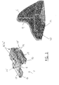
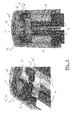
Figures 2 through 7 show details of the windscreen wiper device ofFigure 1 . -
Figure 1 shows a preferred variant of a windscreen wiper device 1 according to the invention. Said windscreen wiper device is built up of anelastomeric wiper blade 2, in the longitudinal sides of which opposinglongitudinal grooves 3 are formed, and oflongitudinal strips 4 made of spring band steel, which are fitted in said longitudinal grooves 3 (figure 7 ). Saidstrips 4 form a flexible carrier element for therubber wiper blade 2, as it were, which is thus biassed in a curved position (the curvature in operative position being that of a windscreen to be wiped). Neighbouring ends 5 ofstrips 4 are interconnected on either side of the windscreen wiper device 1 by means of plastic connectingpieces 6 being separate constructional elements. The windscreen wiper device 1 is further equipped with a connectingdevice 7 for an oscillatingarm 8, and aspoiler 9. -
Figure 2 shows on the left hand how one of the connectingpieces 6 and a metaljoint part 10 can be slidably connected through a snap connection in the direction of the arrow 11, whereasfigure 2 reveals on the right hand the connectingpiece 6 and thejoint part 10 in assembled position. - With reference to
figure 6 relating to a bottom view of thestrips 4, the connectingpiece 6 and thejoint part 10 in assembled position (while thewiper blade 2 being absent), saidstrips 4 are each provided with aprotrusion 12 extending laterally from a longitudinalinterior edge 13 of thestrips 4. When a connectingpiece 6 is slidably mounted onto thejoint part 10 and subsequently onto the neighbouring ends 5 of thestrips 4, a snap or clicking connection is realized, wherein theprotrusions 12 are snapped or clicked between stops 14',14'' ("notches 14") inside thejoint part 10. Eachprotrusion 12 rests in a small groove between these opposing stops 14',14''. Accordingly, thestrips 4 are blocked against any movement in longitudinal direction with respect to the connectingpieces 6/joint parts 10. Eachjoint part 10 is also provided with twoengaging members 15 made integral therewith, wherein saidengaging members 15 engage around thestrips 4 so as to form agroove 16 for sliding thestrips 4 therein. Said engagingmembers 15 ensure that thestrips 4 are blocked against any movement in transversal direction with respect to the connectingpieces 6/joint parts 10. The stop 14' facing away from the free end of the connectingpiece 6 is equipped with an inclined upper surface, so that sliding saidjoint part 10 onto thestrips 4 does not take too much force, whereas once theprotrusion 12 rests inside said groove dismounting thejoint part 10 from thestrips 4 cannot take place easily. The stop 14'' facing towards the free end of the connectingpiece 6 also ensures that the strips are kept at a mutual constant distance, as the upper end of eachstrip 4 is located between said stop 14'' and a (side) wall of the connecting piece 6 (figure 6 ). Each connectingpiece 6 has acavity 17 to accommodate the free end of thespoiler 9. - As can be seen from
figures 2 through 7 , saidjoint part 10 comprises achannel 18 for apart 19 of saidwiper blade 2 that extends from saidstrips 4 in a direction away from the windscreen to be wiped. Saidchannel 18 comprises retaining means in the form of a downwardly extending gripping tooth 20' for gripping saidpart 19 of saidwiper blade 2 for retaining saidjoint part 10 onto saidwiper blade 2. Said gripping tooth 20' is cut from an upper wall of said channel and bent inwardly away from said upper wall towards the windscreen to be wiped. Said retaining means also comprises an end wall 20'' of saidchannel 18. In practice said end wall 20'' may abut against anend wall 21 of the connecting piece 6 (figures 4 and6 ). - Referring to
figures 3 and5 said connectingpiece 6 and saidjoint part 10 are slidably connected by means of a snap connection also, wherein said snap connecting comprise aprotrusion 22 extending laterally from an inner wall 23 of said connectingpiece 6. Saidprotrusion 22 being located betweenstops 24 on thejoint part 10. Saidstops 24 may be formed by the transverse surfaces of arecess 25 inside saidjoint part 10. Each connectingpiece 6 is provided by downwardly extendingarms 26 in one piece therewith for engaging saidjoint part 10. Free ends of saidarms 26 extend inwardly so as to engage saidjoint part 10 in a firm manner. - The present invention is not limited to the embodiment shown, but extends also to other embodiments falling within the scope of the appended claims.
Claims (10)
- A windscreen wiper device comprising an elastic, elongated carrier element, as well as an elongated wiper blade of a flexible material, which can be placed in abutment with a windscreen to be wiped, which wiper blade includes opposing longitudinal grooves on its longitudinal sides, in which grooves spaced-apart longitudinal strips of the carrier element are disposed, wherein neighbouring ends of said longitudinal strips are interconnected by a respective connecting piece, which windscreen wiper device comprises a connecting device for an oscillating wiper arm, characterized in that said strips and said connecting piece are slidably connected by means of a snap connection with the interposition of a joint part.
- A windscreen wiper device according to claim 1, wherein said joint part comprises engaging members engaging around the longitudinal strips so that said strips are mounted in grooves formed by said engaging members.
- A windscreen wiper device according to claim 1 or 2, wherein the snap connection comprises laterally extending means on said strips, and wherein said laterally extending means comprise at least one protrusion extending laterally from an interior edge of each strip, said protrusion being located within the outer contour of each strip and between stops on the joint part.
- A windscreen wiper device according to claim 2 and 3, wherein said joint part comprises a channel for a part of said wiper blade that extends from said strips in a direction away from the windscreen to be wiped, and wherein said channel comprises retaining means for retaining said joint part onto said wiper blade.
- A windscreen wiper device according to claim 4, wherein said retaining means comprises at least one downwardly extending gripping tooth for gripping said part of said wiper blade extending from said strips in a direction away from the windscreen to be wiped.
- A windscreen wiper device according to claim 5, wherein said gripping tooth is cut from an upper wall of said channel and bent inwardly away from said upper wall towards the windscreen to be wiped.
- A windscreen wiper device according to any of the preceding claims 4, 5 or 6, wherein said retaining means comprises an end wall of said channel.
- A windscreen wiper device according to any of the preceding claims 1 through 7, wherein said connecting piece and said joint part are slidably connected by means of a snap connection.
- A windscreen wiper device according to claim 8, wherein said snap connecting comprises laterally extending means on said connecting piece, and wherein said laterally extending means comprise at least one protrusion extending laterally from an inner wall of said connecting piece, said protrusion being located between stops on the joint part.
- A windscreen wiper device according to any of the preceding claims 1 through 9, wherein said joint part and said engaging members are made in one piece of metal.
Priority Applications (7)
| Application Number | Priority Date | Filing Date | Title |
|---|---|---|---|
| ES08103394T ES2366633T3 (en) | 2008-04-04 | 2008-04-04 | WINDSHIELD CLEANING DEVICE THAT INCLUDES AN ALARGATED, ELASTIC CARRIER ELEMENT, AS WELL AS AN ALARGATED WINDSHIELD WASHER RACK OF A FLEXIBLE MATERIAL, WHICH CAN BE LOCATED AGAINST A WINDSHIELD TO BE CLEANED. |
| EP08103394A EP2106979B1 (en) | 2008-04-04 | 2008-04-04 | Windscreen wiper device comprising an elastic, elongated carrier element, as well as an elongated wiper blade of a flexible material, which can be placed in abutment with the windscreen to be wiped |
| PCT/EP2009/053837 WO2009121896A1 (en) | 2008-04-04 | 2009-03-31 | Windscreen wiper device comprising an elastic, elongated carrier element, as well as an elongated wiper blade of a flexible material, which can be placed in abutment with the windscreen to be wiped |
| US12/936,240 US8402595B2 (en) | 2008-04-04 | 2009-03-31 | Windscreen wiper device comprising an elastic, elongated carrier element, as well as an elongated wiper blade of a flexible material, which can be placed in abutment with the windscreen to be wiped |
| JP2011502377A JP5525512B2 (en) | 2008-04-04 | 2009-03-31 | A windscreen wiper device comprising a longitudinal carrier element having elasticity and a longitudinal wiper blade, which can be disposed adjacent to the windshield to be wiped |
| KR1020107024730A KR101592616B1 (en) | 2008-04-04 | 2009-03-31 | Windscreen wiper device comprising an elastic, elongated carrier element, as well as an elongated wiper blade of a flexible material, which can be placed in abutment with the windscreen to be wiped |
| CN2009801106937A CN101980903B (en) | 2008-04-04 | 2009-03-31 | windshield wiper unit |
Applications Claiming Priority (1)
| Application Number | Priority Date | Filing Date | Title |
|---|---|---|---|
| EP08103394A EP2106979B1 (en) | 2008-04-04 | 2008-04-04 | Windscreen wiper device comprising an elastic, elongated carrier element, as well as an elongated wiper blade of a flexible material, which can be placed in abutment with the windscreen to be wiped |
Publications (2)
| Publication Number | Publication Date |
|---|---|
| EP2106979A1 true EP2106979A1 (en) | 2009-10-07 |
| EP2106979B1 EP2106979B1 (en) | 2011-05-18 |
Family
ID=39679370
Family Applications (1)
| Application Number | Title | Priority Date | Filing Date |
|---|---|---|---|
| EP08103394A Active EP2106979B1 (en) | 2008-04-04 | 2008-04-04 | Windscreen wiper device comprising an elastic, elongated carrier element, as well as an elongated wiper blade of a flexible material, which can be placed in abutment with the windscreen to be wiped |
Country Status (7)
| Country | Link |
|---|---|
| US (1) | US8402595B2 (en) |
| EP (1) | EP2106979B1 (en) |
| JP (1) | JP5525512B2 (en) |
| KR (1) | KR101592616B1 (en) |
| CN (1) | CN101980903B (en) |
| ES (1) | ES2366633T3 (en) |
| WO (1) | WO2009121896A1 (en) |
Cited By (9)
| Publication number | Priority date | Publication date | Assignee | Title |
|---|---|---|---|---|
| WO2011042518A1 (en) * | 2009-10-09 | 2011-04-14 | Robert Bosch Gmbh | Wiper blade |
| KR101166494B1 (en) | 2012-04-06 | 2012-07-20 | 유병갑 | Endcap of wiper |
| US20130205531A1 (en) * | 2010-09-09 | 2013-08-15 | Valeo Systèmes d'Essuyage | Device for securing a blade on a wiper |
| KR200475851Y1 (en) * | 2014-01-14 | 2015-01-12 | 유병갑 | An endcap of wiper for vehicle |
| EP2974920A1 (en) * | 2014-07-17 | 2016-01-20 | Valeo Systèmes d'Essuyage | Mounting process for a streamlined flat windscreen wiper |
| WO2016008992A1 (en) * | 2014-07-17 | 2016-01-21 | Valeo Systèmes d'Essuyage | Flat aerodynamic windscreen wiper blade |
| FR3023792A1 (en) * | 2014-07-17 | 2016-01-22 | Valeo Systemes Dessuyage | FLAT WHEAT FLAT BRUSH |
| FR3039112A1 (en) * | 2015-07-24 | 2017-01-27 | Valeo Systemes Dessuyage | DEVICE FOR FIXING A BLADE OF A WIPER BROOM |
| CN106715207A (en) * | 2014-07-17 | 2017-05-24 | 法雷奥系统公司 | Flat aerodynamic windscreen wiper blade |
Families Citing this family (11)
| Publication number | Priority date | Publication date | Assignee | Title |
|---|---|---|---|---|
| GB2499152B (en) * | 2010-11-24 | 2017-10-18 | Trico Products Corp | Beam blade wiper assembly having self-locking end cap |
| US9073518B2 (en) | 2011-09-15 | 2015-07-07 | Asmo Co., Ltd. | Vehicle wiper |
| US8959700B2 (en) * | 2011-09-15 | 2015-02-24 | Asmo Co., Ltd. | Wiper blade |
| KR20160082517A (en) | 2013-11-06 | 2016-07-08 | 페더럴-모걸 모터파츠 코오포레이숀 | Rear windscreen wiper device |
| EP3065979A1 (en) | 2013-11-06 | 2016-09-14 | Federal-Mogul Motorparts Corporation | Windscreen wiper device |
| FR3037892A1 (en) * | 2015-06-29 | 2016-12-30 | Valeo Systemes Dessuyage | EXTENDED END CAP TO BE MOUNTED ON A FLEXIBLE HOLDER AND WIPER BRUSH COMPRISING THE END CAP AND FLEXIBLE SUPPORT. |
| CN108657127B (en) * | 2018-07-02 | 2020-12-29 | 厦门富可汽车配件有限公司 | Improved flow guide protective sleeve, end fastener and windshield wiper |
| JP7368306B2 (en) * | 2020-04-27 | 2023-10-24 | 株式会社ミツバ | wiper blade |
| DE102020209951A1 (en) * | 2020-08-06 | 2022-02-10 | Robert Bosch Gesellschaft mit beschränkter Haftung | Wiper blade device and wiper blade system |
| CN113682263B (en) * | 2021-09-16 | 2023-02-17 | 浙江兄弟之星汽配有限公司 | Windscreen wiper for special vehicle |
| JP7536322B2 (en) * | 2022-04-21 | 2024-08-20 | 丹陽鎮威汽配有限公司 | Sealed wiper structure |
Citations (7)
| Publication number | Priority date | Publication date | Assignee | Title |
|---|---|---|---|---|
| FR2281858A1 (en) * | 1974-08-14 | 1976-03-12 | Sev Marchal | WIPER BLADE |
| DE10245693A1 (en) * | 2002-09-30 | 2004-04-08 | Robert Bosch Gmbh | Windscreen wiping device for vehicle has holder which can be moved from holding position to free position for removing wiper batten |
| EP1683695A1 (en) * | 2005-01-25 | 2006-07-26 | Federal-Mogul S.A. | Windscreen wiper device |
| EP1695881A2 (en) * | 2000-05-25 | 2006-08-30 | Robert Bosch Gmbh | Wiper blade for cleaning vehicle windows |
| US20070061993A1 (en) | 2005-09-19 | 2007-03-22 | Alberee Products, Inc. | Windshield wiper assembly having a body made of spring steel |
| WO2007031260A1 (en) * | 2005-09-13 | 2007-03-22 | Valeo Systemes D'essuyage | Locking device between a wiper blade and a windscreen wiper blade arm |
| DE102005052258A1 (en) * | 2005-11-02 | 2007-05-03 | Robert Bosch Gmbh | Wiper blade for motor vehicle, has spring rails whose ends are connected with each other by strap, where holes are plastically deformed in sides of rails in such a manner that strap is firmly connected with spring rails |
Family Cites Families (8)
| Publication number | Priority date | Publication date | Assignee | Title |
|---|---|---|---|---|
| US2983945A (en) * | 1958-03-12 | 1961-05-16 | Anderson Co | Wiper blade assembly |
| US3626544A (en) * | 1970-09-16 | 1971-12-14 | Roberk Co The | Clip for windshield wiper blade refill |
| JP2995613B2 (en) * | 1996-07-11 | 1999-12-27 | マルエヌ株式会社 | Fixtures to be placed at both ends of the rubber ribbon with the ribbon holder attached to the rubber ribbon holding claw of the stay that constitutes the wiper blade |
| DE60310053T2 (en) * | 2003-06-26 | 2007-04-19 | Federal-Mogul S.A. | Windshield wiper device |
| EP1698533B1 (en) | 2005-03-02 | 2008-09-10 | Federal-Mogul S.A. | Windscreen wiper device |
| DE102006044338A1 (en) * | 2005-09-23 | 2007-04-19 | Shook, William B., Tampa | Manufacturing method of rim for bicycle wheel, involves extruding thin-walled, hollow section having external tab and subjecting hollow section without external tab to buckling when producing rim |
| JP4594249B2 (en) * | 2006-02-14 | 2010-12-08 | アスモ株式会社 | Wiper blade |
| EP1857337B1 (en) | 2006-05-19 | 2009-08-05 | Federal-Mogul S.A. | Windscreen wiper device |
-
2008
- 2008-04-04 ES ES08103394T patent/ES2366633T3/en active Active
- 2008-04-04 EP EP08103394A patent/EP2106979B1/en active Active
-
2009
- 2009-03-31 CN CN2009801106937A patent/CN101980903B/en not_active Expired - Fee Related
- 2009-03-31 US US12/936,240 patent/US8402595B2/en not_active Expired - Fee Related
- 2009-03-31 JP JP2011502377A patent/JP5525512B2/en not_active Expired - Fee Related
- 2009-03-31 KR KR1020107024730A patent/KR101592616B1/en not_active Expired - Fee Related
- 2009-03-31 WO PCT/EP2009/053837 patent/WO2009121896A1/en not_active Ceased
Patent Citations (7)
| Publication number | Priority date | Publication date | Assignee | Title |
|---|---|---|---|---|
| FR2281858A1 (en) * | 1974-08-14 | 1976-03-12 | Sev Marchal | WIPER BLADE |
| EP1695881A2 (en) * | 2000-05-25 | 2006-08-30 | Robert Bosch Gmbh | Wiper blade for cleaning vehicle windows |
| DE10245693A1 (en) * | 2002-09-30 | 2004-04-08 | Robert Bosch Gmbh | Windscreen wiping device for vehicle has holder which can be moved from holding position to free position for removing wiper batten |
| EP1683695A1 (en) * | 2005-01-25 | 2006-07-26 | Federal-Mogul S.A. | Windscreen wiper device |
| WO2007031260A1 (en) * | 2005-09-13 | 2007-03-22 | Valeo Systemes D'essuyage | Locking device between a wiper blade and a windscreen wiper blade arm |
| US20070061993A1 (en) | 2005-09-19 | 2007-03-22 | Alberee Products, Inc. | Windshield wiper assembly having a body made of spring steel |
| DE102005052258A1 (en) * | 2005-11-02 | 2007-05-03 | Robert Bosch Gmbh | Wiper blade for motor vehicle, has spring rails whose ends are connected with each other by strap, where holes are plastically deformed in sides of rails in such a manner that strap is firmly connected with spring rails |
Cited By (17)
| Publication number | Priority date | Publication date | Assignee | Title |
|---|---|---|---|---|
| US9511747B2 (en) | 2009-10-09 | 2016-12-06 | Robert Bosch Gmbh | Wiper blade |
| CN102574507A (en) * | 2009-10-09 | 2012-07-11 | 罗伯特·博世有限公司 | Wiper blade |
| CN102574507B (en) * | 2009-10-09 | 2014-10-29 | 罗伯特·博世有限公司 | Wiper blade |
| RU2555564C2 (en) * | 2009-10-09 | 2015-07-10 | Роберт Бош Гмбх | Wiper brush |
| US9096196B2 (en) | 2009-10-09 | 2015-08-04 | Robert Bosch Gmbh | Wiper blade |
| WO2011042518A1 (en) * | 2009-10-09 | 2011-04-14 | Robert Bosch Gmbh | Wiper blade |
| US20130205531A1 (en) * | 2010-09-09 | 2013-08-15 | Valeo Systèmes d'Essuyage | Device for securing a blade on a wiper |
| US9598052B2 (en) * | 2010-09-09 | 2017-03-21 | Valeo Systèmes d'Essuyage | Device for securing a blade on a wiper |
| KR101166494B1 (en) | 2012-04-06 | 2012-07-20 | 유병갑 | Endcap of wiper |
| KR200475851Y1 (en) * | 2014-01-14 | 2015-01-12 | 유병갑 | An endcap of wiper for vehicle |
| EP2974920A1 (en) * | 2014-07-17 | 2016-01-20 | Valeo Systèmes d'Essuyage | Mounting process for a streamlined flat windscreen wiper |
| FR3023792A1 (en) * | 2014-07-17 | 2016-01-22 | Valeo Systemes Dessuyage | FLAT WHEAT FLAT BRUSH |
| WO2016008992A1 (en) * | 2014-07-17 | 2016-01-21 | Valeo Systèmes d'Essuyage | Flat aerodynamic windscreen wiper blade |
| CN106715207A (en) * | 2014-07-17 | 2017-05-24 | 法雷奥系统公司 | Flat aerodynamic windscreen wiper blade |
| CN107074206A (en) * | 2014-07-17 | 2017-08-18 | 法雷奥系统公司 | Flat aerodynamic windshield wiper blade |
| US11084465B2 (en) | 2014-07-17 | 2021-08-10 | Valeo Systèmes d'Essuyage | Streamlined flat windscreen wiper |
| FR3039112A1 (en) * | 2015-07-24 | 2017-01-27 | Valeo Systemes Dessuyage | DEVICE FOR FIXING A BLADE OF A WIPER BROOM |
Also Published As
| Publication number | Publication date |
|---|---|
| WO2009121896A1 (en) | 2009-10-08 |
| ES2366633T3 (en) | 2011-10-24 |
| EP2106979B1 (en) | 2011-05-18 |
| KR20110009670A (en) | 2011-01-28 |
| CN101980903B (en) | 2012-10-24 |
| CN101980903A (en) | 2011-02-23 |
| JP2011517433A (en) | 2011-06-09 |
| US20110107543A1 (en) | 2011-05-12 |
| US8402595B2 (en) | 2013-03-26 |
| JP5525512B2 (en) | 2014-06-18 |
| KR101592616B1 (en) | 2016-02-05 |
Similar Documents
| Publication | Publication Date | Title |
|---|---|---|
| EP2106979B1 (en) | Windscreen wiper device comprising an elastic, elongated carrier element, as well as an elongated wiper blade of a flexible material, which can be placed in abutment with the windscreen to be wiped | |
| EP1491416B1 (en) | Windscreen wiper device | |
| EP1698533B1 (en) | Windscreen wiper device | |
| EP1568559B2 (en) | A windscreen wiper device | |
| US8341801B2 (en) | Windscreen wiper device | |
| EP2138363B1 (en) | Windscreen wiper device comprising an elastic, elongated carrier element, as well as an elongated wiper blade of a flexible material, which can be placed in abutment with the windscreen to be wiped | |
| EP1683695B1 (en) | Windscreen wiper device | |
| EP2159115B1 (en) | Windscreen wiper device | |
| JP2011517433A5 (en) | ||
| EP2697101B1 (en) | Windscreen wiper device | |
| EP2168823B1 (en) | Windscreen wiper device | |
| EP2790972B1 (en) | Windscreen wiper device | |
| EP2493731A1 (en) | Windscreen wiper device | |
| EP2006173B1 (en) | Windscreen wiper device | |
| WO2018095521A1 (en) | Windscreen wiper device |
Legal Events
| Date | Code | Title | Description |
|---|---|---|---|
| PUAI | Public reference made under article 153(3) epc to a published international application that has entered the european phase |
Free format text: ORIGINAL CODE: 0009012 |
|
| AK | Designated contracting states |
Kind code of ref document: A1 Designated state(s): AT BE BG CH CY CZ DE DK EE ES FI FR GB GR HR HU IE IS IT LI LT LU LV MC MT NL NO PL PT RO SE SI SK TR |
|
| AX | Request for extension of the european patent |
Extension state: AL BA MK RS |
|
| 17P | Request for examination filed |
Effective date: 20100407 |
|
| 17Q | First examination report despatched |
Effective date: 20100510 |
|
| AKX | Designation fees paid |
Designated state(s): BE DE ES FR IT |
|
| GRAP | Despatch of communication of intention to grant a patent |
Free format text: ORIGINAL CODE: EPIDOSNIGR1 |
|
| GRAS | Grant fee paid |
Free format text: ORIGINAL CODE: EPIDOSNIGR3 |
|
| GRAA | (expected) grant |
Free format text: ORIGINAL CODE: 0009210 |
|
| REG | Reference to a national code |
Ref country code: DE Ref legal event code: R096 Ref document number: 602008007003 Country of ref document: DE Effective date: 20110630 |
|
| REG | Reference to a national code |
Ref country code: ES Ref legal event code: FG2A Ref document number: 2366633 Country of ref document: ES Kind code of ref document: T3 Effective date: 20111024 |
|
| PLBE | No opposition filed within time limit |
Free format text: ORIGINAL CODE: 0009261 |
|
| STAA | Information on the status of an ep patent application or granted ep patent |
Free format text: STATUS: NO OPPOSITION FILED WITHIN TIME LIMIT |
|
| 26N | No opposition filed |
Effective date: 20120221 |
|
| REG | Reference to a national code |
Ref country code: DE Ref legal event code: R097 Ref document number: 602008007003 Country of ref document: DE Effective date: 20120221 |
|
| REG | Reference to a national code |
Ref country code: FR Ref legal event code: PLFP Year of fee payment: 9 |
|
| PGFP | Annual fee paid to national office [announced via postgrant information from national office to epo] |
Ref country code: ES Payment date: 20160406 Year of fee payment: 9 |
|
| REG | Reference to a national code |
Ref country code: FR Ref legal event code: PLFP Year of fee payment: 10 |
|
| REG | Reference to a national code |
Ref country code: FR Ref legal event code: PLFP Year of fee payment: 11 |
|
| REG | Reference to a national code |
Ref country code: ES Ref legal event code: FD2A Effective date: 20180627 |
|
| PG25 | Lapsed in a contracting state [announced via postgrant information from national office to epo] |
Ref country code: ES Free format text: LAPSE BECAUSE OF NON-PAYMENT OF DUE FEES Effective date: 20170405 |
|
| PGFP | Annual fee paid to national office [announced via postgrant information from national office to epo] |
Ref country code: FR Payment date: 20200312 Year of fee payment: 13 |
|
| PGFP | Annual fee paid to national office [announced via postgrant information from national office to epo] |
Ref country code: IT Payment date: 20200312 Year of fee payment: 13 |
|
| PG25 | Lapsed in a contracting state [announced via postgrant information from national office to epo] |
Ref country code: FR Free format text: LAPSE BECAUSE OF NON-PAYMENT OF DUE FEES Effective date: 20210430 |
|
| PG25 | Lapsed in a contracting state [announced via postgrant information from national office to epo] |
Ref country code: IT Free format text: LAPSE BECAUSE OF NON-PAYMENT OF DUE FEES Effective date: 20200404 |
|
| PGFP | Annual fee paid to national office [announced via postgrant information from national office to epo] |
Ref country code: DE Payment date: 20250429 Year of fee payment: 18 |
|
| PGFP | Annual fee paid to national office [announced via postgrant information from national office to epo] |
Ref country code: BE Payment date: 20250428 Year of fee payment: 18 |
|
| PG25 | Lapsed in a contracting state [announced via postgrant information from national office to epo] |
Ref country code: IT Free format text: LAPSE BECAUSE OF NON-PAYMENT OF DUE FEES Effective date: 20210404 |