EP2106636B1 - Techniques for high data rates with improved channel reference - Google Patents
Techniques for high data rates with improved channel reference Download PDFInfo
- Publication number
- EP2106636B1 EP2106636B1 EP08728086.3A EP08728086A EP2106636B1 EP 2106636 B1 EP2106636 B1 EP 2106636B1 EP 08728086 A EP08728086 A EP 08728086A EP 2106636 B1 EP2106636 B1 EP 2106636B1
- Authority
- EP
- European Patent Office
- Prior art keywords
- pilot
- power
- base station
- control
- channel
- Prior art date
- Legal status (The legal status is an assumption and is not a legal conclusion. Google has not performed a legal analysis and makes no representation as to the accuracy of the status listed.)
- Active
Links
Images


Classifications
-
- H—ELECTRICITY
- H04—ELECTRIC COMMUNICATION TECHNIQUE
- H04W—WIRELESS COMMUNICATION NETWORKS
- H04W52/00—Power management, e.g. Transmission Power Control [TPC] or power classes
- H04W52/04—Transmission power control [TPC]
- H04W52/06—TPC algorithms
- H04W52/14—Separate analysis of uplink or downlink
- H04W52/146—Uplink power control
-
- H—ELECTRICITY
- H04—ELECTRIC COMMUNICATION TECHNIQUE
- H04W—WIRELESS COMMUNICATION NETWORKS
- H04W52/00—Power management, e.g. Transmission Power Control [TPC] or power classes
- H04W52/04—Transmission power control [TPC]
- H04W52/18—TPC being performed according to specific parameters
- H04W52/26—TPC being performed according to specific parameters using transmission rate or quality of service QoS [Quality of Service]
- H04W52/267—TPC being performed according to specific parameters using transmission rate or quality of service QoS [Quality of Service] taking into account the information rate
-
- H—ELECTRICITY
- H04—ELECTRIC COMMUNICATION TECHNIQUE
- H04W—WIRELESS COMMUNICATION NETWORKS
- H04W52/00—Power management, e.g. Transmission Power Control [TPC] or power classes
- H04W52/04—Transmission power control [TPC]
- H04W52/30—Transmission power control [TPC] using constraints in the total amount of available transmission power
- H04W52/32—TPC of broadcast or control channels
- H04W52/325—Power control of control or pilot channels
Definitions
- the following description relates generally to wireless communications, and more particularly to an improved uplink pilot.
- Wireless communication systems are widely deployed to provide various types of communication; for instance, voice and/or data may be provided via such wireless communication systems.
- a typical wireless communication system, or network can provide multiple users access to one or more shared resources.
- these systems may be multiple-access systems capable of supporting communication with multiple users by sharing the available system resources (e.g., bandwidth and transmit power).
- Examples of such multiple-access systems include code division multiple access (CDMA) systems, time division multiple access (TDMA) systems, frequency division multiple access (FDMA) systems, and orthogonal frequency division multiple access (OFDMA) systems.
- CDMA code division multiple access
- TDMA time division multiple access
- FDMA frequency division multiple access
- OFDMA orthogonal frequency division multiple access
- Coherent demodulation of a data channel typically relies on the derivation of the phase and amplitude changes introduced by the transmission link.
- higher data rates on a transmission link require a better phase and amplitude reference in order to perform well.
- This amplitude and phase reference is usually given by a pilot sequence or channel.
- SNR signal-to-noise ratio
- Mbit/s the signal-to-noise ratio of the channel carrying the pilot
- DPCCH dedicated physical control channel
- the up and down commands issued by the inner-loop of the fast power control is based on the SNR measure on the pilot bits at the base station.
- current deployments of base stations in current versions of W-CDMA cannot differentiate the following from each other: a) an increase in the transmit power of the DPCCH initiated by the UE (i.e., because of the high data rate transmission), and b) an improvement in the radio link (better path loss, reduction in interference level).
- the systems observe that the SNR of the pilot is increased beyond the target SNR, and issue a down command. The correct behavior would be for the base station to only issue a down command for the case where there is an improvement in the radio link.
- the base station when the base stations issue a down command in the case of an increase in the transmit power of the DPCCH, the base station operates to effectively reduce the SNR for the high data rate transmission and thereby degrades its performance. Furthermore, with current practices, after the UE has finished transmitting the high rate packet, improved efficiencies (e.g., boost) in the pilot transmit power will be removed since the UE, having executed the undesirable down commands, results in a pilot with a low SNR such that lower data rate transmissions can fail.
- improved efficiencies e.g., boost
- US-A1-2005/0014523 discloses an apparatus, and an associated method, for facilitating closed-loop power control in a radio communication system, such as upon reverse links defined in a CDMA2000, cellular communication system.
- Rate indications are modulated by a modulator upon a control channel carrier signal to form a modulated data segment.
- the modulated data segment is repeated a selected number of times to form a concatenated sequence of modulated data segments.
- the modulated data segments are of sub-frame lengths and the concatenated sequences of a frame length.
- US-A1-2003/0050084 there is disclosed a method for controlling the transmit power of a mobile terminal on a mobile communication system.
- the serving base station in the active set for the mobile station controls the mobile station transmit power on the rate control channel.
- the non-serving base stations control the transit power on the reverse traffic channel.
- an access terminal comprises a processing unit, a memory operably connected to the processing unit, a receive circuitry operably connected to the processing unit and a transmit circuitry having a power amplifier used in both single carrier and multi-carrier operations.
- the transmit circuitry is operably connected to the processing unit, and the access terminal also comprises a throttle control unit operably connected to the power amplifier, adapted to throttle power to provide sufficient headroom for the power amplifier.
- a component can be, but is not limited to being, a process running on a processor, a processor, an object, an executable, a thread of execution, a program, and/or a computer.
- an application running on a computing device and the computing device can be a component.
- One or more components can reside within a process end/or thread of execution and a component can be localized on one computer and/or distributed between two or more computers.
- these components can execute from various computer readable media having various data structures stored thereof.
- the components may communicate by way of local and/or remote processes such as in accordance with a signal having one or more data packets (e.g. , data from one component interacting with another component in a local system, distributed system, and/or across a network such as the Internet with other systems by way of the signal).
- components of systems described herein may be rearranged and/or conplemented by additional components in order to facilitate achieving the various aspects, goals, advantages, etc., described with regard thereto, and are not limited to the precise configurations set forth in a given figure, as will be appreciated by one skilled in the art.
- a wireless terminal or user equipment can also be called a system, subscriber unit, subscriber station, mobile station, mobile, mobile device, remote station, remote terminal, UE, user terminal, terminal, wireless communication device, user agent, or user device.
- a wireless terminal or UE can be a cellular telephone, a cordless telephone, a Session Initiation Protocol (SIP) phone, a wireless local loop (WLL) station, a personal digital assistant (PDA), a handheld device having wireless connection capability, computing device, or other processing device connected to a wireless modem.
- SIP Session Initiation Protocol
- WLL wireless local loop
- PDA personal digital assistant
- a base station can be utilized for communicating with wireless terminal(s) and can also be referred to as an access point, Node B, or some other terminology.
- computer-readable media can include but are not limited to magnetic storage devices (e.g. , hard disk, floppy disk, magnetic strips, etc. ), optical disks ( e . g ., compact disk (CD), digital versatile disk (DVD), etc. ), smart cards, and flash memory devices ( e . g ., EPROM, card, stick, key drive, etc. ) .
- magnetic storage devices e.g. , hard disk, floppy disk, magnetic strips, etc.
- optical disks e . g ., compact disk (CD), digital versatile disk (DVD), etc.
- smart cards e . g ., EPROM, card, stick, key drive, etc.
- various storage media described herein can represent one or more devices and/or other machine-readable media for storing information.
- a carrier wave can be employed to carry computer-readable electronic data or instructions such as those used in transmitting and receiving voice mail, in accessing a network such as a cellular network, or in instructing a device to perform a specified function.
- machine-readable medium can include, without being limited to, wireless channels and various other media capable of storing, containing, and/or carrying instruction(s) and/or data.
- the word "exemplary” is used herein to mean serving as an example, instance, or illustration. Any aspect or design described herein as “exemplary” is not necessarily to be construed as preferred or advantageous over other aspects or designs. Rather, use of the word exemplary is intended to present concepts in a concrete fashion.
- the term “or” is intended to mean an inclusive “or” rather than an exclusive “or”. That is, unless specified otherwise, or clear from context, "X employs A or B” is intended to mean any of the natural inclusive permutations. That is, if X employs A; X employs B; or X employs both A and B, then "X employs A or B" is satisfied under any of the foregoing instances.
- the articles “a” and “an” is used in this application and the appended claims should generally be construed to mean “one or more” unless specified otherwise or clear from context to be directed to a singular form.
- the terms to "infer” or “inference” refer generally to the process of reasoning about or inferring states of the system, environment, and/or user from a set of observations as captured via events and/or data. Inference can be employed to identify a specific context or action, or can generate a probability distribution over states, for example. The inference can be probabilistic-that is, the computation of a probability distribution over states of interest based on a consideration of data and events. Inference can also refer to techniques employed for composing higher-level events from a set of events and/or data. Such inference results in the construction of new events or actions from a set of observed events and/or stored event data, whether or not the events are correlated in close temporal proximity, and whether the events and data come from one or several event and data sources.
- CDMA Code Division Multiple Access
- TDMA Time Division Multiple Access
- FDMA Frequency Division Multiple Access
- OFDMA Orthogonal FDMA
- SC-FDMA Single-Carrier FDMA
- a CDMA network may implement a radio technology such as Universal Terrestrial Radio Access (UTRA), cdma2000, etc.
- UTRA includes Wideband-CDMA (W-CDMA), TD-CDMA, and TD-CDMA.
- cdma2000 covers IS-2000, IS-95, and IS-856 standards.
- a TDMA network may implement a radio technology such as Global System for Mobile Communications (GSM).
- GSM Global System for Mobile Communications
- An OFDMA network may implement a radio technology such as Evolved UTRA (E-UTRA), IEEE 802.11, IEEE 802.16, IEEE 802.20, Flash-OFDM®, etc.
- E-UTRA, E-UTRA, and GSM are part of Universal Mobile Telecommunication System (UMTS).
- UMTS Universal Mobile Telecommunication System
- LTE Long Term Evolution
- UTRA, E-UTRA, GSM, UMTS, and LTE are described in documents from an organization named "3rd Generation Partnership Project" (3GPP).
- cdma2000 is described in documents from an organization named "3rd Generation Partnership Project 2" (3GPP2).
- UEs are provided the ability to autonomously increase (boost) the level of the channel carrying the pilot.
- this channel is called the Dedicated Physical Control Channel (DPCCH).
- DPCCH Dedicated Physical Control Channel
- the UE can increase the transmit power of the DPCCH as a function of the transmission format the UE uses on the data channel - i.e., as a function of the data rate of the data channel.
- the UE can illustratively operate to decrease the power of the DPCCH by the amount of the boost in order to resume operation at the normal power level.
- the level of a control channel can be increased (boosted), such as the Enhanced Dedicated Physical Control Channel in W-CDMA.
- the E-DPCCH can be first decoded, then the modulation symbols are clipped according to a selected scheme to transform the E-DPCCH into a pilot reference.
- the E-DPCCH can then be then combined with the DPCCH to provide an improved phase and amplitude reference for demodulating other channels such as the DPDCH.
- fast power control can be deployed to mitigate rapid changes in the pilot channel SNR at the receiver due to variations of the propagation channel and level of interference.
- fast power control as is currently used on the uplink of W-CDMA, generally relies on two loops: the inner loop and the outer loop.
- the inner loop can perform an operation where an exemplary base station (e.g., Node B, RNC, or other infrastructure element) operatively measures the SNR of the pilot bits and compares the measured SNR to a target SNR to issue an UP or DOWN command to one or more cooperating wireless terminals (e.g., user equipment - UE) based on this comparison so as to maintain the measured SNR close to the target SNR.
- an exemplary base station e.g., Node B, RNC, or other infrastructure element
- a cooperating wireless terminals e.g., user equipment - UE
- the UE receives an UP command it can operatively increase the power of its channels by a step-size.
- the UE receives a DOWN command from any of the cells (e.g., cooperating base station) in its active-set of cooperating cells it can operatively decrease the power of the channels by a step-size.
- the up and down commands issued by the inner-loop of the fast power control is generally based on the SNR measure on the pilot bits at the base station.
- W-CDMA base stations are inoperative to differentiate the following from each other; a) an increase in the transmit power of the DPCCH initiated by the UE because it is transmitting a high data rate transmission, and b) an improvement in the radio link (better path loss, reduction in interference level, other)
- the base station observes that the SNR of the pilot is increased beyond the target SNR, and issues a down command.
- the desired behavior would be for the base station to issue a down command only for case (b).
- the base station By issuing a down command in case (a) the base station reduces the SNR for the high data rate transmission and thereby degrades its performance. Furthermore, after the UE has finished transmitting the high rate packet, the boost in the pilot transmit power will stop. As such, the UE having executed the undesirable down commands, the pilot may be at such a low SNR that any lower data rate transmissions may fail.
- the herein described systems and methods provide a wireless communications system where an exemplare base station illustratively operatively measures the pilot and detects a jump in its level.
- the exemplary base station if the exemplary base station detects an increase in the pilot level of more than ⁇ dB from the previously observed time slot, the exemplary base station operatively stores data representative of a boosted pilot.
- the exemplary base station operates the power control loop in conventional manner and can operate to perform one or more of the following illustrative operations to detect a possible boosted pilot and switches the power control to operate in one of the modes as described by the following illustrative operations.
- the exemplary base station can monitor the pilot channel and can detect a jump in its (signal to noise ration) level.
- the exemplary base station if the exemplary base station detects an increase in the pilot level of more than a selected decibel value from a previously transmitted time slot, the exemplary base station operates in a selected power control mode.
- the selected power control mode comprises ignoring the SNR measures during the next time transmission interval (TTI), and transmitting power control commands to one or more UEs such that the one or more UEs will not change its respective average transmit power.
- the exemplary base station can operate to normalize the measured pilot SNR to compensate for the pilot boost.
- the normalized SNR can then be used by an exemplary power control inner-loop.
- the exemplary base station can estimate the pilot boost by comparing the pilot SNR received during a boosted timeslot to the pilot SNR received during a time when it was not boosted. Operatively, the result of this estimate can be used to normalize the measured SNR.
- exemplary base station can disable power control on the firs: slot of a wireless transmission that may have a boosted pilot, operating under the assumption that the normalized SNR did not change from the previous time slot.
- an exemplary base station can use the difference between successive time slots to update an estimate of the normalized SNR.
- the normalized SNR can then be used by the inner-loop power control.
- an exemplary base station can measure the power or SNR received on the enhanced dedicated physical control channel (E-DPDCH).
- E-DPDCH enhanced dedicated physical control channel
- the exemplary base station can operate to render the pilot as being able to be boosted and performs one or more of selected power mode operations.
- E-DPCCH enhanced dedicated physical control channel
- E-DPDCH enhanced dedicated physical data channel
- the SNR of the E-DPCCH can be estimated by the exemplary base station and used for inner-loop power control.
- the estimated SNR of the E-DPCCH can be adjusted to represent the power of the normalized DPCCH and power control can be illustratively operated employing the adjusted SNR estimate.
- the exemplary base station can disable power control at the beginning of every TTI where the user equipment (UE) may transmit with a boosted pilot.
- the exemplary base station can operatively determine when the UE may transmit with a boosted pilot because the exemplary base station can provide control over the UE transmissions through one or more message grants, and through DTX control.
- the power control can be re-enabled when the exemplary base station decodes the E-DPCCH.
- the E-DPCCH can communicate which format is being transmitted from the exemplary UE as well as whether the UE is using a pilot boost on the E-DPDCH.
- the exemplary base station can utilize the result of the E-DPCCH to normalize the DPCCH pilot SNR estimate.
- the exemplary base station can disable power control in the event that the UE operates to boost the pilot.
- the exemplary base station can monitor the instances for which the UE operates to boost the pilot and limit their frequency in occurrence by communication of grant messages to one or more cooperating wireless terminals.
- the exemplary base station can transmit to one or more wireless terminals an absolute grant message to allow the one or more wireless terminals (e.g., UEs) to transmit a high data rate utilizing a boosted pilot for a specific TTI.
- UEs can operatively ignore "down" commands from non-serving cells when they are transmitting a boosted pilot.
- the outer loop can perform an operation where an exemplary base station operatively measures the quality of service (QoS) of the received data from one or more cooperating wireless terminals (e.g., the block error rate (BLER) or bit error rate (BER)) and can adjust the target SNR as necessary such as to reach a desired QoS.
- QoS quality of service
- a measure of the SNR on the pilot can be used to derive variations in the quality of the radio link to adjust the transmit power of the channels that are transmitted by the UE.
- EUL enhanced uplink
- data can generally be transmitted on a channel named the E-DPDCH.
- the pilot reference can be still carried on the DPCCH and can be used for coherent demodulation of the E-DPDCH as well as other channels.
- the uplink in a wireless system is a resource shared by cooperating UEs.
- an exemplary base station can maximize the overall uplink performance by controlling the amount of uplink resources used by each individual UE.
- absolute grant messages can be deployed to achieve the desired uplink resource control.
- an absolute grant message is a message sent on the downlink by a base station scheduler to directly adjust the granted rate of one UE under its control.
- the absolute grant message itself can include multiple fields that are multiplexed together, and transmitted on a downlink channel named the E-AGCH. These fields can comprise: Absolute Grant Value - this field indicates the maximum EUL data to pilot ratio (E-DPDCH/DPCCH) that the UE is allowed to use in the next transmission; Absolute Grant Scope: this field indicates the applicability of the Absolute Grant. (It can take two different values, "Per HARQ process" or "All HARQ processes", which can indicate whether the HARQ process activation/de-activation will affect one or all processes
- the pilot boost with the DPDCH to nominal DPCCH power ratio can be combined into a new absolute message metric, where, illustratively, the nominal DPCCH power is the power of the DPCCH had it not been boosted.
- m ⁇ ed ⁇ c + ⁇ bc ⁇ I computed in linear domain where ⁇ ed and ⁇ c are the amplitude gains of the E-DPDCH and DPCCH respectively, and where ⁇ bc is the amplitude ratio of the boosted DPCCH to the nominal DPCCH.
- the same procedure to compute the new absolute message metric can be used, but on the other channel.
- ⁇ ed , ⁇ c , and ⁇ ec are the amplitude gains of the E-DPDCH, DPCCH, and E-DPCCH respectively
- ⁇ bcc is the amplitude gain of the boosted E-DPCCH
- a ed and A ec are the amplitude ratio of the E-DPDCH to DPCCH and un-boosted E-DPCCH to DPCCH respectively
- a b-ec is the amplitude ratio of the boosted E-DPCCH to DPCCH
- E ec _ boost is the ratio of the amplitude increase due to boosting the E-DPCCH to the amplitude of the DPCCH.
- the power of channels other than the DPCCH can be set relative to the power of the DPCCH.
- an increase in 1 dB in the DPCCH power can result in a power increase for other channels by 1 dB.
- the UE if power boost is deployed, the UE operatively sets the power of channels other than the DPCCH relative to the nominal DPCCH, i.e., the power of the DPCCH if it had not been boosted.
- the DPCCH power can be arbitrarily boosted without affecting the power of the other channels transmitted by the UE.
- the power of the E-DPDCH can be adjusted and specified relative to the nominal DPCCH power, or relative to the boosted DPCCH power.
- data can be transmitted by one or more cooperating wireless terminals on the E-DPDCH in fixed intervals of time (e.g., transmit time intervals (TTI)).
- TTI transmit time intervals
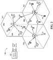
- Base station 100 includes multiple antenna group, one including 104 and 106, another including 108 and 110, and an additional group including 112 and 114. In Fig. 1 , only two antennas are shown for each antenna group; however, more or fewer antennas may be utilized for each antenna group.
- User equipment 116 UE is in communication with antennas 112 and 114, where antennas 112 and 114 transmit information to UE 116 over downlink 120 and receive information from UE 116 over uplink 118.
- UE 122 is in communication with antennas 106 and 108, where antennas 106 and 108 transmit information to UE 122 over downlink 126 and receive information from UE 122 over uplink 124.
- communication links 118, 120, 124 and 126 may use different frequencies for communication.
- downlink 120 may use a different frequency than that used by uplink 118.
- antenna groups each are designed to communicate to UEs in a sector of the areas covered by base station 100.
- the transmitting antennas of base station 100 may utilize beamforming in order to improve the signal-to-noise ratio of downlinks for the different UEs 116 and 124.
- a base station may be a fixed station used for communicating with the terminals and may also be referred to as an access point, a Node B, or some other terminology.
- a user equipment (UE) may also be called an access terminal, a wireless communication device, terminal, or some other terminology.
- FIG. 2 illustrates a wireless communication system 200 with multiple base stations 210 and multiple user equipments (UEs) 220 as may be utilized in conjunction with one or more aspects of the herein described systems and methods
- a base station is generally, although not necessarily, a fixed station that communicates with the terminals and may also be called an access point, a Node B, or some other terminology.
- Each base station 210 provides communication coverage for a particular geographic area, illustrated as three geographic areas, labeled 202a, 202b, and 202c,
- the term "cell" can refer to a base station and/or its coverage area depending on the context in which the term is used. To improve system capacity, a base station coverage area may be partitioned into multiple smaller areas (e.g.
- each smaller area can be served by a respective base transceiver subsystem (BTS).
- BTS base transceiver subsystem
- the term "sector” can refer to a BTS and/or its coverage area depending on the context in which the term is used. For a sectorized cell, the BTSs for all sectors of that cell are typically co-located within the base station for the cell.
- the transmission techniques described herein may be used for a system with sectorized cells as well as a system with un-sectorized cells.
- base station is used generically for a fixed station that serves a sector as well as a fixed station that serves a cell.
- Each terminal 220 may communicate with zero, one, or multiple base stations on the downlink and uplink at any given moment.
- the downlink (or forward link) refers to the communication link from the base stations to the terminals
- the uplink (or reverse link) refers to the communication link from the terminals to the base stations.
- a system controller 230 couples to base stations 210 and provides coordination and control for base stations 210.
- base stations 210 may communicate with one another as needed. Additional channels of the downlink (e.g. , control channel) may be transmitted from multiple base stations to one UE. Uplink data communication may occur from one UE to one or more bass stations via one or more antennas at the terminals 220 and or at the base stations 210, as described above with respect to FIG. 1 .
- Additional channels of the downlink e.g. , control channel
- Uplink data communication may occur from one UE to one or more bass stations via one or more antennas at the terminals 220 and or at the base stations 210, as described above with respect to FIG. 1 .
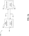
- FIG. 3A illustrates an exemplary non-limiting high-level block diagram of a system that facilitates pilot channel optimization according to various aspects of the herein described systems and methods.
- the system 300A includes user equipment 302 that is communicatively coupled to a base station 304 in a wireless manner.
- base station 304 is providing voice and/or data services to UE 302 over a downlink 310 and receiving communications from user equipment 302 over an uplink 312, such as a CDMA or single carrier frequency division multiple access (SC-FDMA) uplink.
- User equipment 302 can be mobile in nature, such that quality associated with signals received from base station 304 can vary as UE 302 translates to a different geographic region.
- User equipment 302 can include a pilot feedback mechanism 306 which is responsive to control one or more power operations of the user equipment responsive to instructions provided by pilot control mechanism 308 located at base station 305 that operatively monitors pilot signals in accordance with the schemes discussed herein to enable channel condition estimation among other functions.
- pilot control mechanism 308 located at base station 305 that operatively monitors pilot signals in accordance with the schemes discussed herein to enable channel condition estimation among other functions.
- UE 302 and/or base station 304 can include other ancillary components which facilitates, among other functions, communication of associated information or data used to adaptively determine the pilot allocation scheme.
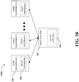
- FIG. 3B illustrates a base station 304 receiving signals from a plurality of UEs 302 such that uplink pilot signals are monitored according to various aspects of the herein described systems and methods.
- Base station 304 is shown receiving signals from a plurality of UEs 302 (1 to Z), Z being an integer.
- Logical Control Channels comprise Broadcast Control Channel (BCCH), which is a downlink (DL) channel for broadcasting system control information; Paging Control Channel (PCCH), which is a downlink channel that transfers paging information; and Multicast Control Channel (MCCH), which is point-to-multipoint downlink channel used for transmitting Multimedia Broadcast and Multicast Service (MBMS) scheduling and control information for one or several Multicast Traffic Channels (MTCHs).
- BCCH Broadcast Control Channel
- PCCH Paging Control Channel
- MCCH Multicast Control Channel
- MBMS Multimedia Broadcast and Multicast Service
- Dedicated Control Channel is point-to-point bi-directional channel that transmits dedicated control information and used by UEs 302 having an RRC connection.
- logical traffic channels comprise a Dedicated Traffic Channel (DTCH), which is point-to-point bi-directional channel, dedicated to one UE for the transfer of user information; and a MTCH which is a Point-to-multipoint downlink channel for transmitting traffic data.
- DTCH Dedicated Traffic Channel
- MTCH Point-to-multipoint downlink channel for transmitting traffic data.
- transport channels are classified into downlink and uplink.
- Downlink transport channels comprise the Dedicated Channel (DCH), the Broadcast Channel (BCH), the Forward Access Channel (FACH), the High Speed Downlink Shared Channel (HS-DSCH), and the Paging Channel (PCH) broadcasted over the entire cell and mapped to PHY resources, which can be used for other control/traffic channels.
- the uplink transport channels comprise the Dedicated Channel (DCH), the Enhanced Dedicated Channel (E-DCH), and the Random Access Channel (RACH).
- the PHY channels comprise a set of DL channels and UL channels.
- HS-DSCH is a High Speed Downlink Shared Channel
- CPICH is a Common Pilot Channel
- a Slot is a time duration of 0.666 milliseconds (ms).
- FIG. 4 depicts an exemplary non-limiting pilot optimization illustrative implementation.
- wireless communications system 400 comprises user equipment 402 and base station 404 operative to communicate data and operation signals over communications channels 412 and 410 (e.g., pilot channel).
- base station pilot control mechanism 408 can monitor pilot channel conditions on user equipment 402 such that one or more power condition signals (not shown) can be provided to user equipment power control mechanism 406 operative to control the power of pilot channel (e.g., to perform a pilot boost) of user equipment 402 according to one or more selected conditions (e.g., high data rates).
- the power control can be performed according to one or more of the illustrated operations described herein (i.e., as described in the "Pilot Boost" section).
- the apparatus 500 can be a base station 304 or a portion thereof or user equipment 302 or a portion thereof (such as a secure digital (SD) card coupled to a processor).
- Apparatus 500 can include a memory 502 that retains various instructions with respect to signal processing, scheduling communications, requesting measurement gaps, and/or the like. For instance, if apparatus 500 is user equipment as described below in connection with FIGS. 11-12 and 15 , memory 502 can include instructions for analysing quality of signals on an uplink and/or downlink channel with respect to a particular base station. Further, memory 502 can comprise instructions for pilot channel optimisation.
- memory 502 can comprise instructions for receiving and processing uplink pilot channel data from a base station 304 in order to facilitate a pilot channel optimization according to a predetermined scheme, in accordance with various aspects of the herein described systems and methods.
- memory 502 can comprise instructions for facilitating transmission of the optimized pilot channel.
- the above examplary instructions and other suitable instructions can be retained within memory 502, and a processor 504 can be utilized in connection with executing the instructions (depending upon, for instance, number of active streams, frequency starting position, e tc .),
- apparatus 500 can be a base station and/or a portion thereof as described below in connection with FIGS. 9-10 and 14 .
- memory 502 can include instructions for receiving an indication that user equipment serviced by apparatus 500 is taking measurements with respect to other technologies and/or frequencies.
- Memory 502 can additionally include instructions for determining and transmitting uplink pilot channel data n order to facilitate performing one or more power control operations on UE 302 according to a predetermined scheme, in accordance with various aspects of the herein described systems and methods.
- memory 502 can further include instructions for facilitating reception of the optimized pilot channel.
- Processor 504 can be employed to execute instructions retained within memory 502. While several examples have been provided, it is understood that instructions described in the form of methodologies (e.g., FIGS. 6-7 ) can be included within memory 502 and executed by processor 504.
- FIGS. 6 and 7 particular high-level methodologies for optimizing pilot channel power conditions in accordance with various illustrative implementations are illustrated. While, for purposes of simplicity of explanation, the methodologies are shown and described as a series of acts, it is to be understood and appreciated that the methodologies are not limited by the order of acts, as some acts can occur in different orders and/or concurrently with other acts from that shown and described herein. For example, those skilled in the art will understand and appreciate that a methodology could alternatively be represented as a series of interrelated states or events, such as in a state diagram. Moreover, not all illustrated acts may be utilized to implement a methodology in accordance with one or more embodiments.
- FIG. 6 illustrates one particular high-level methodology 600 facilitating uplink pilot optimization in connection with pilot optimization schemes described herein.
- uplink pilot channel information necessary to facilitate pilot optimization scheme according to a predetermined function of the power of the pilot channel is determined by the base station 304 or a portion thereof.
- the respective uplink pilot channel information for one or more UEs 302 to facilitate UE 302 pilot optimization according to the predetermined function related to the pilot channel condition and/or state is received and monitored.
- UE 302 receives and processes pilot optimization commands from base station 304, or a portion thereof, according to the predetermined function and the respective uplink pilot channel information.
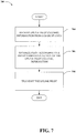
- FIG. 7 illustrates one particular high-level methodology 700 for facilitating uplink pilot optimization in connection with pilot optimization schemes described herein.
- UE 302 or a portion thereof controls the power of the pilot channel at 706 according to a predetermined function of the uplink pilot channel information.
- the UE 302 or a portion thereof. transmits the power controlled pilot.
- FIG. 8 depicts an examplary communication system 800 implemented in accordance with various aspects including multiple cells: cell I 802, cell M 804. Note that neighboring cells 802 and 804 overlap slightly, as indicated by cell boundary region 868, thereby creating potential for signal interference between signals transmitted by base stations in neighboring cells' boundary regions; each boundary region is shared between two adjacent sectors.
- Sector boundary regions provide potential for signal interference between signals transmitted by base stations in neighboring sectors.
- Line 816 represents a sector boundary region between sector I 810 and sector II 812;
- line 818 represents a sector boundary region between sector II 812 and sector III 814;
- line 820 represents a sector boundary region between sector III 814 and sector 1 810.
- cell M 804 includes a first sector, sector I 822, a second sector, sector II 824, and a third sector, sector III 826.
- Line 828 represents a sector boundary region between sector I 822 and sector II 824;
- line 830 represents a sector boundary region between sector II 824 and sector III 826;
- line 832 represents a boundary region between sector III 826 and sector I 822.
- Cell I 802 includes a base station (BS), base station I 806, and a plurality of end nodes (ENs) (e .g ., wireless terminals) in each sector 810, 812, 814.
- Sector I 810 includes EN(1) 836 and EN(X) 838 coupled to BS 806 via wireless links 840, 842, respectively;
- sector II 8:2 includes EN(1') 844 and EN(X') 846 coupled to BS 806 via wireless links 848, 850, respectively;
- sector III 814 includes EN(1") 852 and EN(X") 854 coupled to BS 806 via wireless links 856, 858, respectively.
- cell M 804 includes base station M 308, and a plurality of end nodes (ENs) in each sector 822, 824, 826.
- Sector 1 822 includes EN(1) 836' and EN(X) 838' coupled to 3S M 808 via wireless links 840', 842', respectively;
- sector II 824 includes EN(1') 844' and EN(X') 846' coupled to BS M 808 via wireless links 848', 850', respectively;
- sector 3 826 includes EN(1'') 852' and EN(X") 854' coupled to BS 808 via wireless links 856', 858', respectively.
- System 300 also includes a network node 860 which is coupled to BS I 806 and BS M 808 via network links 862, 864, respectively.
- Network node 860 is also coupled to other network nodes, e . g ., other base stations, AAA server nodes, intermediate nodes, routers, etc. and the Internet via network link 866.
- Network links 862, 864, 866 can be, e . g ., fiber optic cables.
- Each end node, e . g ., EN(1) 836 can be a wireless terminal including a transmitter as well as a receiver.
- the wireless terminals, e.g., EN(1) 836 can move through system 800 and can communicate via wireless links with the base station in the cell in which the EN is currently located.
- the wireless terminals, (WTs), e.g., EN(1) 836 can communicate with peer nodes, e.g., other WTs in system 800 or outside system 800 via a base station, e.g., BS 806, and/or network node 860.
- WTs, e . g ., EN(1) 836 can be mobile communications devices such as cell phones, personal data assistants with wireless modems, etc.
- Respective base stations or portions thereof can perform pilot uplink channel information determination and transmission. Additionally, respective base stations or portions thereof can perform uplink pilot demultiplexing according to the various aspects provided herein.
- the wireless terminals or portions thereof can use the provided respective uplink pilot channel information to facilitate adaptively multiplexing pilots by varying the pilot channel bandwidth and frequency location per SB 402 in time according to a predetermined function of the number of active streams according to the various aspects provided herein. Additionally, wireless terminals or portions thereof can transmit multiplexed pilots to the respective base stations
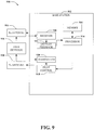
- FIG. 9 illustrates a system that can be utilized in connection with adaptive uplink pilot multiplexing schemes with respect to user equipment.
- System 900 comprises a base station 902 with a receiver 910 that receives signal(s) from one or more user devices 904 by way of one or more receive antennas 906, and transmits to the one or more user devices 904 through a plurality of transmit antennas 908.
- receive antennas 906 and transmit antennas 908 can be implemented using a single set of antennas.
- Receiver 910 can receive information from receive antennas 906 and is operatively associated with a demodulator 912 that demodulates received information.
- Receiver 910 can be, for example, a Rake receiver (e.g., a technique that individually processes multi-path signal components using a plurality of baseband correlators, ..), an MMSE-based receiver, or some other suitable receiver for separating out user devices assigned thereto, as will be appreciated by one skilled in the art. For instance, multiple receivers can be employed (e.g., one per receive antenna), and such receivers can communicate with each other to provide improved estimates of user data. Demodulated symbols are analyzed by a processor 914 similar to processor 1106 described below with regard to FIG. 11 , and is coupled to a memory 916 that stores information related to user device assignments, lookup tables related thereto and the like. Receiver output for each antenna can be jointly processed by receiver 910 and/or processor 914.
- a modulator 918 can multiplex the signal for transmission by a transmitter 920 through transmit antennas 908 to user devices 904.
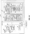
- FIG. 10 illustrates an examplary base station 1000 in accordance with various aspects of the present invention.
- Base station 1000 or portions thereof implements various aspect of the herein described systems and methods.
- base station 1000 can determine pilot uplink channel information determination for subsequent transmission to facilitate adaptive pilot multiplexing in associated user equipment.
- Base station 1000 can be used as any one of base stations 806, 808 of the system 800 of FIG. 8 .
- the base station 1000 includes a receiver 1002, a transmitter 1004, a processor 1006, e.g., CPU, an input/output interface 1008 and memory 1010 coupled together by a bus 1009 over which various elements 1002, 1004, 1006, 1008, and 1010 can interchange data and information.
- a bus 1009 over which various elements 1002, 1004, 1006, 1008, and 1010 can interchange data and information.
- Sectorized antenna 1003 coupled to receiver 1002 is used for receiving data and other signals, e.g., channel reports, from wireless terminals transmissions from each sector within the base station's cell and can comprise one or more receive antennas.
- Sectorized antenna 1005 coupled to transmitter 1004 is used for transmitting data and other signals, e.g., control signals, pilot signal, beacon signals, etc . to wireless terminals 1200 (see FIG. 12 ) within each sector of the base station's cell.
- base station 1000 can employ multiple receivers 1002 and multiple transmitters 1004, e.g., an individual receiver 1002 for each sector and an individual transmitter 1004 for each sector. As described above, it is to be appreciated that various modifications are possible.
- Processor 1006 can be, e.g., a general purpose central processing unit (CPU).
- Processor 1006 controls operation of base station 1000 under direction of one or more routines 1018 stored in memory 1010 and implements the methods.
- I/O interface 1008 provides a connection to other network nodes, coupling the BS 1000 to other base stations, access routers, AAA server nodes, etc ., other networks, and the Internet.
- Memory 1010 includes routines 1018 and data/information 1020.
- Data/information 1020 includes data 1036, tone subset allocation sequence information 1038 including downlink strip-symbol time information 1040 and downlink tone information 1042, and wireless terminal (WT) data/info 1044 including a plurality of sets of WT information: WT 1 info 1046 and WT N info 1060.
- Each set of WT info, e.g., WT 1 info 1046 includes data 1048, terminal ID 1050, sector ID 1052, uplink channel information 1054, downlink channel information 1056, and mode information 1058.
- Routines 1018 include communications routines 1022 and base station control routines 1024.
- Base station control routines 1024 includes a scheduler module 1026 and signaling routines 1028 including a tone subset allocation routine 1030 for strip-symbol periods, ⁇ ther downlink tone allocation hopping routine 1032 for the rest of symbol periods, e.g., non strip-symbol periods, and a beacon routine 1034.
- Data 1036 includes data to be transmitted that will be sent to encoder 1014 of transmitter 1004 for encoding prior to transmission to WTs, and received data from WTs that has been processed through decoder 1012 of receiver 1002 following reception.
- Downlink strip-symbol time information 1040 includes the frame synchronization structure information, such as the superslot, beaconslot, and ultraslot structure information and information specifying whether a given symbol period is a strip-symbol period, and if so, the index of the strip-symbol period and whether the strip-symbol is a resetting point to truncate the tone subset allocation sequence used by the base station.
- Downlink tone information 1042 includes information including a carrier frequency assigned to the base station 1000, the number and frequency of tones, and the set of tone subsets to be allocated to the strip-symbol periods, and other cell and sector specific values such as slope, slope index and sector type.
- Data 1043 can include data that WT1 1200 has received from a peer node, data that WT 1 1200 desires to be transmitted to a peer node, and downlink channel quality report feedback information.
- Terminal ID 1050 is a base station 1000 assigned ID that identifies WT 1 1200.
- Sector ID 1052 includes information identifying the sector in which WT1 1200 is operating. Sector ID 1052 can be used, for example, to determine the sector type.
- Uplink channel information 1054 includes information identifying channel segments that have been allocated by scheduler 1026 for WT1 1200 to use, e . g ., uplink traffic channel segments for data, dedicated uplink control channels for requests, power control, timing control, number of active streams etc .
- Each uplink channel assigned to WT1 1200 includes one or more logical tones, each logical tone following an uplink hopping sequence according to various aspects of the present invention.
- Downlink channel information 1056 includes information identifying channel segments that have been allocated by scheduler 1026 to curry data and/or information to WT1 1200, e . g ., downlink traffic channel segments for user data.
- Each downlink channel assigned to WTI 1200 includes one or more logical tones, each following a downlink hopping sequence.
- Mode information 1058 includes information identifying the state of operation of WT1 1200, e . g, sleep, hold, on.
- Communications routines 1022 control the base station 1000 to perform various communications operations and implement various communications protocols.
- Base station control routines 1024 are used to control the base station 1000 to perform basic base station functional tasks, e.g., signal generation and reception, scheduling, and to implement the steps of the method of some aspects including transmitting signals to wireless terminals using the tone subset allocation sequences during the strip-symbol periods.
- Signaling routine 1028 controls the operation of receiver 1002 with its decoder 1012 and transmitter 1004 with its encoder 1014.
- the signaling routine 1028 is responsible for controlling the generation of transmitted data 1036 and control information.
- Tone subset allocation routine 1030 constructs the tone subset to be used in a strip-symbol period,using the method of the aspect and using data/information 1020 including downlink strip-symbol time info 1040 and sector ID 1052.
- the downlink tone subset allocation sequences will be different for each sector type in a cell and different for adjacent cells.
- the WTs 1200 receive the signals in the strip-symbol periods in accordance with the downlink tone subset allocation sequences; the base station 1000 uses the same downlink tone subset allocation sequences in order to generate the transmitted signals.
- Other downlink tone allocation hopping routine 1032 constructs downlink tone hopping sequences, using information including cownlink tone information 1042, and downlink channel information 1056, for the symbol periods other than the strip-symbol periods.
- the downlink data tone hopping sequences are synchronized across the sectors of a cell.
- Beacon routine 1034 controls the transmission of a beacon signal, e . g ., a signal of relatively high power concentrated on one or a few tones, which can be used for synchronization purposes, e . g ., to synchronize the frame timing structure of the downlink signal and therefore the tone subset allocation sequence with respect to an ultra-slot boundary.
- FIG. 11 illustrates a system 1100 that can be utilized in connection with pilot optimization schemes as described herein.
- System 1100 comprises a receiver 1102 that receives a signal from, for instance, one or more receive antennas, and performs typical actions thereon (e.g., filters, amplifies, downconverts, ...) the received signal and digitizes the conditioned signal to obtain samples.
- a pilot control mechanism 1104 can provide received pilot symbols to a processor 1106 for channel estimation.
- Processor 1106 can be a processor dedicated to analyzing information received by receiver component 1102 and/or generating information for transmission by a transmitter 1114.
- Processor 1106 can be a processor that controls one or more portions of system 1100, and/or a processor that analyzes information received by receiver 1102, generates information for transmission by a transmitter 1114, and controls one or more portions of system 1100.
- System 1100 can include an optimization component 1108 that can optimize performance of user equipment before, during, and/or after performance of measurements with respect to one or more technologies and/or frequencies. Optimization component 1108 can be incorporated into the processor 1106. It is to be appreciated that optimization component 1108 can include optimization code that performs utility based analysis in connection with requesting measurement gaps. The optimization code can utilize artificial intelligence based methods in connection with performing inference and/or probabilistic determinations and/or statistical-based determination in connection with encoding and decoding schemes.
- System (user equipment) 1100 can additionally comprise memory 1110 that is operatively coupled to processor 1106 and that stores information such as measurement gap information, scheduling information, and the like, wherein such information can be employed in connection with allocating requesting measurement gaps and performing measurements during a measurement gap.
- Memory 1110 can additionally store protocols associated with generating lookup tables, etc., such that system 1100 can employ stored protocols and/or algorithms to increase system capacity.
- the data store (e.g., memories) components described herein can be either volatile memory or nonvolatile memory, or can include both volatile and nonvolatile memory.
- nonvolatile memory can include read only memory (ROM), programmable ROM (PROM), electrically programmable ROM (EPROM), electrically erasable ROM (EEPROM), or flash memory.
- Volatile memory can include random access memory (RAM), which acts as external cache memory.
- RAM is available in many forms such as synchronous RAM (SRAM), dynamic RAM (DRAM), synchronous DRAM (SDRAM), double data rate SDRAM (DDR SDRAM), enhanced SDRAM (ESDRAM), Synchlink DRAM (SLDRAM), and direct Rambus RAM (DRRAM).
- SRAM synchronous RAM
- DRAM dynamic RAM
- SDRAM synchronous DRAM
- DDR SDRAM double data rate SDRAM
- ESDRAM enhanced SDRAM
- SLDRAM Synchlink DRAM
- DRRAM direct Rambus RAM
- the memory 1110 is intended to comprise, without being limited to, these and any other suitable types of memory.
- Processor 1106 is connected to a symbol pilot feedback mechanism 1112 and transmitter 1 114 that transmits the modulated signal.
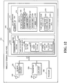
- FIG. 12 illustrates an exemplary wireless terminal (e.g., end node, mobile device, etc.) 1200 which can be used as any one of the wireless terminals (e.g., EN(1) 836, of the system 800 shown in FIG. 8 ).
- Wireless terminal 1200 includes a receiver 1202 including a decoder 1212, a transmitter 1204 including an encoder 1214, a processor 1206 and memory 1208, which are coupled together by a bus 1210 over which the various elements 1202, 1204, 1206, 1208 can interchange data and information.
- Antenna 1203 used for receiving signals from a base station is coupled to receiver 1202.
- Antenna 1205 used for transmitting signals, e.g., to a base station is coupled to transmitter 204.
- multiple transmit and receive antennas, receivers, etc. in the base station and user equipment can be used.
- multiple users can transmit and receive signals from a base station having multiple transmit and receive antennas, receivers, etc.
- the processor 1206 e.g., a CPU, controls the operation of the wireless terminal 1200 and implements methods by executing routines 1220 and using data/information 1222 in memory 1208.
- Data/information 1222 includes user data 1234, user information 1236, and tone subset allocation sequence information 1250, in the examplary case of an OFDMA communication system.
- User data 1234 can include data, intended for a peer node, which can be ronted to encoder 1214 for encoding prior to transmission by transmitter 1204 to base station 1000, and data received from the base station 1000 which has been processed by the decoder 1212 in receiver 1202.
- User information 1236 includes uplink channel information 1238, downlink channel information 1240, terminal ID information 1242, base station ID information 1244, sector ID information 1246, and mode information 1248.
- Uplink channel information 1238 includes information identifying uplink channel segments that have been assigned by base station 1000 for wireless terminal 1200 to use when transmitting to the base station 1000.
- Uplink channels can include uplink traffic channels, dedicated uplink control channels, e.g., request channels, power control channels and timing control channels.
- each uplink channel includes one or more logic tones, each logical tone following an uplink tone hopping sequence.
- the uplink hopping sequences are different between each sector type of a cell and between adjacent cells.
- Downlink channel information 1240 includes information identifying downlink channel segments that have been assigned by a base station to WT 1200 for use when the base station is transmitting data/information to WT 1200.
- Downlink channels can include downlink traffic channels and assignment channels, each downlink channel including one or more logical tones each logical tone following a downlink hopping sequence, which is synchronized between each sector of the cell.
- User info 1236 also includes terminal ID information 1242, which is a base station 1000 assigned identification, base station ID information 1244 which identifies the specific base station 1000 that WT 1200 has established communications with, and sector ID info 1246 which identifies the specific sector of the cell where WT 1200 is presently located.
- terminal ID information 1242 which is a base station 1000 assigned identification
- base station ID information 1244 which identifies the specific base station 1000 that WT 1200 has established communications with
- sector ID info 1246 which identifies the specific sector of the cell where WT 1200 is presently located.
- base station ID 1244 provides a cell slope value
- sector ID info 1246 provides a sector index type; the cell slope value and sector index type can be used to derive tone hopping sequences.
- Mode information 1248 also included in user info 1236 identifies whether the WT 1200 is in sleep mode, hold mode, or on mode.
- tone subset allocation sequence information 1250 includes downlink strip-symbol time information 1252 and downlink tone information 1254.
- Downlink tone info 1254 includes information including a carrier frequency assigned to the base station 1000, the number and frequency of tones, and the set of tone subsets to be allocated to the strip-symbol periods, and other cell and sector specific values such as slope, slope index and sector type.
- Routines 1220 include communications routines 1224 and wireless terminal control routines 1226. Communications routines 1224 control the various communications protocols used by WT 1200. Wireless terminal control routines 1226 controls basic wireless terminal 1200 functionality including the control of the receiver 1202 and transmitter 1204, Wireless terminal control routines 1226 include the signaling routine 1228 In some OFDMA embodiments, tone subset a location routine 1230 uses user data/info 1222 including downlink channel information 1240, base station ID info 1244, e.g., slope index and sector type, and downlink tone information 1254 in order to generate the downlink tone subset allocation sequences in accordance with some embodiments and process received data transmitted from base station 1000.
- tone subset a location routine 1230 uses user data/info 1222 including downlink channel information 1240, base station ID info 1244, e.g., slope index and sector type, and downlink tone information 1254 in order to generate the downlink tone subset allocation sequences in accordance with some embodiments and process received data transmitted from base station 1000.
- Some illustrative implementations can be implemented using software, hardware and/or a combination of software and hardware. Some embodiments are directed to an apparatus, e.g., a mobile node such as a mobile terminal, a base station, or a communications system which implements some illustrative implementation. Some illustrative implementations are also directed to methods, e.g., method of controlling and/or operating mobile nodes, base stations and/or communications systems, e.g., hosts, in accordance with some illustrative implementations.
- Some illustrative implementations are also directed to machine readable medium, e.g., ROM, RAM, CDs, hard discs, etc., which include machine readable instructions for controlling a machine to implement one or more steps in accordance with some illustrative implementations.
- machine readable medium e.g., ROM, RAM, CDs, hard discs, etc.
- nodes described herein are implemented using one or more modules to perform the steps corresponding to one or more methods of some illustrative implementations, for example, signal processing, message generation and/or transmission steps,
- various features of some illustrative implementations are implemented using modules.
- modules can be implemented using software, hardware or a combination of software and hardware.
- Many of the above described methods or method steps can be implemented using machine executable instructions, such as software, included in a machine readable medium such as a memory device, e . g ., RAM, floppy disk, etc., to control a machine, e .
- some embodiments are directed to a machine-readable medium including machine executable instructions for causing a machine, e.g., processor and associated hardware, to perform one or more of the steps of the above-described method(s).
- the methods and apparatus of some illustrative implementations can be and in various embodiments are, used with CDMA, orthogonal frequency division multiplexing (OFDM), SC-FDMA, and/or various other types of communications techniques which can be used to provide wireless communications links between access nodes and mobile nodes.
- the access nodes are implemented as base stations which establish communications links with mobile nodes using OFDM and/or CDMA.
- the mobile nodes are implemented as notebook computers, personal data assistants (PDAs), or other portable devices including receiver/transmitter circuits and logic and/or routines, for implementing the methods of some embodiments.
- inferences can be made regarding determining uplink pilot channel information.
- the term to "infer” or “inference” refers generally to the process of reasoning about or inferring states of the system, environment, and/or user, mobile device, active uplink streams, and base station from a set of observations as captured via events and/or data. Inference can be employed to identify a specific context or action, or can generate a probability distribution over states, for example. The inference can be probabilistic-that is, the computation of a probability distribution over states of interest based on a consideration of data and events. Inference can also refer to techniques employed for composing higher-level events from a set of events and/or data. Such inference results in the construction of new events or actions from a set of observed events and/or stored event data, whether or not the events are correlated in close temporal proximity, and whether the events and data come from one or several event and data sources.
- one or more methods presented above can include making inferences pertaining to determining active uplink streams to facilitate adaptive uplink pilot multiplexing.
- an inference may be made related tc estimating a probability of a desired signal being differentiable from one or more undesired signals based on a set of uplink pilot signals.
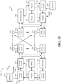
- FIG. 13 illustrates an exemplary non-limiting block diagram of a communication system incorporating pilot optimization in accordance with various aspects of the invention, where a transmitter system 1310 (e.g., base station, base station, etc.) and a receiver system 1350 (UE, user equipment, mobile node, etc.) in a MIMO system 1300.
- a transmitter system 1310 e.g., base station, base station, etc.
- a receiver system 1350 UE, user equipment, mobile node, etc.
- traffic data for a number of data streams is provided from a data source 1312 to a transmit (TX) data processor 1314.
- TX data processor 1314 formats, codes, and interleaves the traffic data for each data stream based on a particular coding scheme selected for that data stream to provide coded data.
- transmitter system 1310 facilitates pilot optimization schemes by transmitting to the receiver system 1350 uplink pilot channel information.
- the coded data for each data stream can be multiplexed with pilot data using OFDM techniques.
- the pilot data is typically a known data pattern that is processed in a known manner and can be used at the receiver system to estimate the channel response.
- the data rate, coding, and modulation for each data stream may be determined by instructions performed by processor 1330.
- TX processor 1320 may further process the modulation symbols (e.g., for OFDM).
- TX processor 1320 then provides N T modulation symbol streams to N T transmitters (TMTR) 1322a through 1322t.
- TMTR TX transmitters
- TX processor 1320 applies beamforming weights to the symbols of the data streams and to the antenna from which the symbol is being transmitted.
- Each transmitter 1322 receives and processes a respective symbol stream to provide one or mere analog signals, and further conditions (e.g., amplifies, filters, and upconverts) the analog signals to provide a modulated signal suitable for transmission over the MIMO channel.
- N T modulated signals from transmitters 1322a through 1322t are then transmitted from N T antennas 1324a through 1324t, respectively.
- the transmitted modulated signals are received by N R antennas 1352a through 1352r and the received signal from each antenna 1352 is provided to a respective receiver (RCVR) 1354a through 1354r.
- Each receiver 1354 conditions (e.g., filters, amplifies, and downconverts) a respective received signal, digitizes the conditioned signal to provide samples, and further processes the samples to provide a corresponding "received" symbol stream.
- An RX data processor 1360 then receives and processes the N R received symbol streams from N R receivers 1354 based on a particular receiver processing technique to provide N T "detected" symbol streams.
- the RX data processor 1360 then demodulates, deinterleaves, and decodes each detected symbol stream to recover the traffic data for the data stream.
- the processing by RX data processor 1360 is complementary to that performed by TX MIMO processor 1320 and TX data processor 1314 at transmitter system 1310.
- a processor 1370 periodically determines which pre-coding matrix to use as described above.
- Processor 1370 formulates a reverse link message comprising a matrix index portion and a rank value portion.
- the reverse link message may comprise various types of information regarding the communication link and/or the received data stream.
- receiver system 1350 in response to receiving respective uplink pilot channel information from transmitter system 1310, receiver system 1350 optimizes the pilot channel according to a predetermined function.
- the reverse link message is then processed by a TX data processor 1338, which also receives traffic data for a number of data streams from a data source 1336, modulated by a modulator 1380, conditioned by transmitters 1354a through 1354r, and transmitted back to transmitter system 1310.
- the modulated signals from receiver system 1350 are received by antennas 1324, conditioned by receivers 1322, demodulated by a demodulator 1340, and processed by a RX data processor 1342 to extract the reverse link message transmitted by the receiver system 1350
- Processor 1330 determines which pre-coding matrix to use for determining the beamforming weights and then processes the extracted message.
- transmitter system 1310 in response to receiving multiplexed pilots from receiver system 1350, demultiplexes the multiplexed pilot channel according to the predetermined function and the respective uplink pilot channel information.
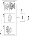
- apparatus 1400 that facilitates pilot optimization according to various non-limiting illustrative implementations of the herein described systems and methods.
- apparatus 1400 may reside at least partially within a base station.
- apparatus 1400 is represented as including functional blocks, which may be functional blocks that represent functions implemented by a processor, software, or combination thereof (e.g., firmware)
- Apparatus 1400 includes a logical grouping 1402 of electrical components that can act in conjunction.
- logical grouping 1402 can include an electrical component for determining and transmitting uplink pilot channel information in a base station 1404.
- uplink pilot channel information can include a number of one or more active streams to be multiplexed, a number of available resource blocks, and/or a pilot starting frequency position, any combination thereof, and the like.
- logical grouping 1402 can include an electrical component for receiving signals representative of pilot control 1406 as described in further detail supra in connection with FIG. 4, 6-7 .
- Logical grouping 1402 can further include an electrical component for processing pilot control signals according to a predetermined function of the uplink pilot channel information 1408.
- apparatus 1400 can include a memory 1410 that retains instructions for executing functions associated with electrical components 1404, 1406, and 1408. While shown as being external to memory 1410, it is to be understood that one or more of electrical components 1404, 1406, and 1408 may exist within memory 1410.
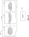
- Apparatus 1500 may reside at least partially within a wireless terminal, for instance. It is to be appreciated that apparatus 1500 is represented as including functional blocks, which may be functional blocks that represent functions implemented by a processor, or combination thereof ( e . g ., firmware). Apparatus: 1500 includes a logical grouping 1502 of electrical components that can act in conjunction. For instance, logical grouping 1502 may include an electrical component for receiving and processing uplink pilot channel information 1504. For example, electrical component 1504 can include an electrical component for receiving and processing uplink pilot channel information as described above with respect to FIG. 14 .
- logical grouping 1502 can include an electrical component for processing pilot control data depending on the uplink pilot channel information 1506 as described in further detail supra in connection with FIG. 4, 6-7 . Further, logical grouping 1502 can include an electrical component for transmitting pilot feedback data 1508. Additionally, apparatus 1500 may include a memory 1510 that retains instructions for executing functions associated with electrical components 1504, 1506, and 1508. While shown as being external to memory 1510, it is to be understood that one or more of electrical components 1504, 1506, and 1508 may exist within memory 1510.
- the processing units within an user equipment or a network device may be implemented within one or more application specific integrated circuits (ASICs), digital signal processors (DSPs), digital signal processing devices (DSPDs), programmable logic devices (PLDs), field programmable gate arrays (FPGAs), processors, controllers, micro-controllers, microprocessors, other electronic units designed to perform the functions described herein, or a combination thereof.
- ASICs application specific integrated circuits
- DSPs digital signal processors
- DSPDs digital signal processing devices
- PLDs programmable logic devices
- FPGAs field programmable gate arrays
- processors controllers, micro-controllers, microprocessors, other electronic units designed to perform the functions described herein, or a combination thereof.
- a code segment may represent ⁇ . procedure, a function, a subprogram, a program, a routine, a subroutine, a module, a software package, a class, or any combination of instructions, data structures, or program statements,
- a code segment may be coupled to another code segment or a hardware circuit by passing and/or receiving information, data, arguments, parameters, or memory contents.
- Information, arguments, parameters, data, etc. may be passed, forwarded, or transmitted using any suitable means including memory sharing, message passing, token passing, network transmission, etc.
- the techniques described herein may be implemented with modules ( e . g ., procedures, functions, and so on) that perform the functions described herein.
- the software codes may be stored in memory units and executed by processors.
- a memory unit may be implemented within the processor or external to the processor, in which case it can be communicatively coupled to the processor through various means,
Landscapes
- Engineering & Computer Science (AREA)
- Computer Networks & Wireless Communication (AREA)
- Signal Processing (AREA)
- Quality & Reliability (AREA)
- Mobile Radio Communication Systems (AREA)
- Cable Transmission Systems, Equalization Of Radio And Reduction Of Echo (AREA)
Applications Claiming Priority (3)
| Application Number | Priority Date | Filing Date | Title |
|---|---|---|---|
| US88608507P | 2007-01-22 | 2007-01-22 | |
| US12/017,287 US8081997B2 (en) | 2007-01-22 | 2008-01-21 | Power and/or data rate control based on pilot channel information |
| PCT/US2008/051711 WO2008091897A2 (en) | 2007-01-22 | 2008-01-22 | Techniques for high data rates with improved channel reference |
Publications (2)
| Publication Number | Publication Date |
|---|---|
| EP2106636A2 EP2106636A2 (en) | 2009-10-07 |
| EP2106636B1 true EP2106636B1 (en) | 2020-09-16 |
Family
ID=39639567
Family Applications (1)
| Application Number | Title | Priority Date | Filing Date |
|---|---|---|---|
| EP08728086.3A Active EP2106636B1 (en) | 2007-01-22 | 2008-01-22 | Techniques for high data rates with improved channel reference |
Country Status (10)
Families Citing this family (37)
| Publication number | Priority date | Publication date | Assignee | Title |
|---|---|---|---|---|
| KR101172521B1 (ko) * | 2005-08-05 | 2012-08-10 | 노키아 코포레이션 | 용량 증대를 위한 동적 업링크 제어 채널 게이팅 |
| WO2008130922A2 (en) * | 2007-04-18 | 2008-10-30 | Cisco Technology, Inc. | Hybrid time-spatial multiplexing for wireless broadcast messages through antenna radiation beam synthesis |
| US8861418B2 (en) * | 2007-07-10 | 2014-10-14 | Qualcomm Incorporated | Methods and apparatus for supporting group communications with data re-transmission support |
| US8495232B2 (en) * | 2007-07-10 | 2013-07-23 | Qualcomm Incorporated | Methods and apparatus for supporting broadcast communications in a peer to peer network |
| US7961698B2 (en) * | 2007-07-10 | 2011-06-14 | Qualcomm Incorporated | Methods and apparatus for controlling interference to broadcast signaling in a peer to peer network |
| US8694662B2 (en) * | 2007-07-10 | 2014-04-08 | Qualcomm Incorporated | Method and apparatus for communicating transmission requests to members of a group and/or making group related transmission decisions |
| KR100991793B1 (ko) | 2007-12-31 | 2010-11-03 | 엘지전자 주식회사 | 셀간 간섭 감소 방법 |
| US8411766B2 (en) | 2008-04-09 | 2013-04-02 | Wi-Lan, Inc. | System and method for utilizing spectral resources in wireless communications |
| US8868121B2 (en) * | 2008-09-29 | 2014-10-21 | Nokia Corporation | Control channel gain factor with data channel scaling |
| US8274885B2 (en) * | 2008-10-03 | 2012-09-25 | Wi-Lan, Inc. | System and method for data distribution in VHF/UHF bands |
| US20100118834A1 (en) | 2008-11-07 | 2010-05-13 | Amit Kalhan | Device beacon for communication management for peer to peer communications |
| US8107391B2 (en) | 2008-11-19 | 2012-01-31 | Wi-Lan, Inc. | Systems and etiquette for home gateways using white space |
| US8335204B2 (en) * | 2009-01-30 | 2012-12-18 | Wi-Lan, Inc. | Wireless local area network using TV white space spectrum and long term evolution system architecture |
| CN101841496B (zh) * | 2009-03-17 | 2013-03-13 | 上海贝尔股份有限公司 | 多输入多输出系统中用于多小区协作通信的方法及装置 |
| JP4854758B2 (ja) * | 2009-04-15 | 2012-01-18 | 株式会社エヌ・ティ・ティ・ドコモ | 無線基地局 |
| US20100309317A1 (en) * | 2009-06-04 | 2010-12-09 | Wi-Lan Inc. | Device and method for detecting unused tv spectrum for wireless communication systems |
| US8937872B2 (en) | 2009-06-08 | 2015-01-20 | Wi-Lan, Inc. | Peer-to-peer control network for a wireless radio access network |
| EP2282591B1 (en) * | 2009-07-01 | 2012-09-12 | Ntt Docomo, Inc. | Mobile and base station transceiver apparatus for communicating |
| KR101273082B1 (ko) * | 2009-12-15 | 2013-06-10 | 한국전자통신연구원 | 상향 링크 전송 전력 제어를 위한 피드백 생성 방법 및 시스템 |
| CN102208967B (zh) * | 2010-03-31 | 2014-04-09 | 中兴通讯股份有限公司 | 一种lte终端非自适应重传功率控制的方法及装置 |
| US9144040B2 (en) | 2010-04-01 | 2015-09-22 | Futurewei Technologies, Inc. | System and method for uplink multi-antenna power control in a communications system |
| EP2553983B1 (en) | 2010-04-02 | 2016-10-12 | Intel Corporation | System and method for performance enhancement in heterogeneous wireless access networks |
| US9020555B2 (en) * | 2010-04-05 | 2015-04-28 | Intel Corporation | System and method for performance enhancement in heterogeneous wireless access network employing distributed antenna system |
| US9363761B2 (en) | 2010-04-05 | 2016-06-07 | Intel Corporation | System and method for performance enhancement in heterogeneous wireless access network employing band selective power management |
| KR20120018266A (ko) | 2010-08-20 | 2012-03-02 | 삼성전자주식회사 | 직교 주파수 분할 다중 접속 방법을 사용하는 무선 통신 시스템에서 기지국의 전력 증폭기 소모 전력 제어 방법 및 장치 |
| GB2484287A (en) * | 2010-10-04 | 2012-04-11 | Vodafone Ip Licensing Ltd | Selecting base station radio systems for receiving and combining OFDM signals from a mobile station |
| US8942750B2 (en) * | 2011-01-07 | 2015-01-27 | Apple Inc. | Power control in a mobile device |
| US20140106679A1 (en) * | 2011-06-08 | 2014-04-17 | Tomohiro Kanauchi | Wireless communication system, receiver |
| US9094424B2 (en) * | 2012-01-18 | 2015-07-28 | Nokia Technologies Oy | Method, apparatus, and computer program product for digital stream swapping between signal sources |
| US9735940B1 (en) | 2012-04-12 | 2017-08-15 | Tarana Wireless, Inc. | System architecture for optimizing the capacity of adaptive array systems |
| US9252908B1 (en) | 2012-04-12 | 2016-02-02 | Tarana Wireless, Inc. | Non-line of sight wireless communication system and method |
| US10110270B2 (en) | 2013-03-14 | 2018-10-23 | Tarana Wireless, Inc. | Precision array processing using semi-coherent transceivers |
| US10499456B1 (en) | 2013-03-15 | 2019-12-03 | Tarana Wireless, Inc. | Distributed capacity base station architecture for broadband access with enhanced in-band GPS co-existence |
| US10348394B1 (en) | 2014-03-14 | 2019-07-09 | Tarana Wireless, Inc. | System architecture and method for enhancing wireless networks with mini-satellites and pseudollites and adaptive antenna processing |
| WO2016017117A1 (ja) * | 2014-07-28 | 2016-02-04 | 日本電気株式会社 | 移動無線通信システム |
| US10491438B2 (en) | 2017-05-01 | 2019-11-26 | At&T Intellectual Property I, L.P. | Systems and methods for reinforcing signals on coupled channels during idle periods |
| WO2020111987A1 (en) * | 2018-11-26 | 2020-06-04 | Telefonaktiebolaget Lm Ericsson (Publ) | Transmission power control for a radio base station |
Family Cites Families (11)
| Publication number | Priority date | Publication date | Assignee | Title |
|---|---|---|---|---|
| JP3286247B2 (ja) * | 1998-05-08 | 2002-05-27 | 松下電器産業株式会社 | 無線通信システム |
| US7190964B2 (en) | 2001-08-20 | 2007-03-13 | Telefonaktiebolaget Lm Ericsson (Publ) | Reverse link power control in 1xEV-DV systems |
| KR100547847B1 (ko) * | 2001-10-26 | 2006-01-31 | 삼성전자주식회사 | 이동통신 시스템에서 역방향 링크의 제어 장치 및 방법 |
| US7092731B2 (en) * | 2003-03-06 | 2006-08-15 | Lucent Technologies Inc. | Method for improving capacity of a reverse link channel in a wireless network |
| US7369501B2 (en) * | 2003-04-29 | 2008-05-06 | Lg Electronics Inc. | Apparatus and method for controlling reverse-link data transmission rate during handoff |
| US20050014523A1 (en) | 2003-06-05 | 2005-01-20 | Zhouyue Pi | Apparatus, and an associated method, for facilitating power control in a radio communication system that provides for data communications at multiple data rates |
| GB0326365D0 (en) | 2003-11-12 | 2003-12-17 | Koninkl Philips Electronics Nv | A radio communication system,a method of operating a communication system,and a mobile station |
| CN1617479A (zh) * | 2003-11-14 | 2005-05-18 | 北京三星通信技术研究有限公司 | 在宽带码分多址上行专用信道增强中支持导频增强的方法 |
| EP1830489B1 (en) * | 2004-11-19 | 2016-02-24 | NTT DoCoMo, Inc. | Mobile communication method and mobile station |
| US7574393B2 (en) | 2005-07-01 | 2009-08-11 | Rbc Capital Markets Corporation | Index rebalancing |
| US7734262B2 (en) | 2005-07-18 | 2010-06-08 | Rashid Ahmed Akbar Attar | Method and apparatus for reverse link throttling in a multi-carrier wireless communication system |
-
2008
- 2008-01-21 US US12/017,287 patent/US8081997B2/en active Active
- 2008-01-22 EP EP08728086.3A patent/EP2106636B1/en active Active
- 2008-01-22 BR BRPI0806753-8A patent/BRPI0806753B1/pt active IP Right Grant
- 2008-01-22 HU HUE08728086A patent/HUE052276T2/hu unknown
- 2008-01-22 JP JP2009547382A patent/JP2010517437A/ja active Pending
- 2008-01-22 RU RU2009131732/09A patent/RU2422996C2/ru active
- 2008-01-22 ES ES08728086T patent/ES2835174T3/es active Active
- 2008-01-22 CN CN201611069551.9A patent/CN106912093B/zh active Active
- 2008-01-22 WO PCT/US2008/051711 patent/WO2008091897A2/en active Application Filing
- 2008-01-22 CA CA2674532A patent/CA2674532C/en active Active
-
2012
- 2012-05-11 JP JP2012109409A patent/JP5819250B2/ja active Active
- 2012-05-11 JP JP2012109408A patent/JP5819249B2/ja active Active
- 2012-05-21 JP JP2012115850A patent/JP5410569B2/ja active Active
-
2014
- 2014-02-10 JP JP2014023412A patent/JP2014123970A/ja active Pending
- 2014-02-10 JP JP2014023419A patent/JP2014123971A/ja active Pending
Non-Patent Citations (1)
| Title |
|---|
| None * |
Also Published As
| Publication number | Publication date |
|---|---|
| CA2674532C (en) | 2012-11-27 |
| EP2106636A2 (en) | 2009-10-07 |
| US8081997B2 (en) | 2011-12-20 |
| JP2010517437A (ja) | 2010-05-20 |
| US20080214196A1 (en) | 2008-09-04 |
| JP2012199969A (ja) | 2012-10-18 |
| JP2012199952A (ja) | 2012-10-18 |
| HUE052276T2 (hu) | 2021-04-28 |
| JP5819249B2 (ja) | 2015-11-18 |
| ES2835174T3 (es) | 2021-06-22 |
| JP2012199951A (ja) | 2012-10-18 |
| JP5819250B2 (ja) | 2015-11-18 |
| RU2009131732A (ru) | 2011-02-27 |
| WO2008091897A3 (en) | 2008-09-18 |
| BRPI0806753A2 (pt) | 2011-09-13 |
| JP5410569B2 (ja) | 2014-02-05 |
| WO2008091897A2 (en) | 2008-07-31 |
| RU2422996C2 (ru) | 2011-06-27 |
| JP2014123971A (ja) | 2014-07-03 |
| CN106912093A (zh) | 2017-06-30 |
| CA2674532A1 (en) | 2008-07-31 |
| CN106912093B (zh) | 2022-02-08 |
| BRPI0806753B1 (pt) | 2020-03-24 |
| JP2014123970A (ja) | 2014-07-03 |
Similar Documents
| Publication | Publication Date | Title |
|---|---|---|
| EP2106636B1 (en) | Techniques for high data rates with improved channel reference | |
| KR101136668B1 (ko) | Ofdma/cdma 액세스 단말기에 대한 디지털 및 아날로그 전력 제어 | |
| US7966033B2 (en) | Serving sector directed power control | |
| KR101137112B1 (ko) | 서빙 섹터 간섭 브로드캐스트 및 대응하는 역방향 링크 트래픽 전력 제어 | |
| EP2115891B1 (en) | Uplink power control for lte | |
| CA2697939C (en) | Reverse link traffic power control | |
| US20080045260A1 (en) | Power Settings for the Sounding Reference signal and the Scheduled Transmission in Multi-Channel Scheduled Systems | |
| EP2373100A2 (en) | Reverse link traffic power control for LBC FDD | |
| EP3289813A1 (en) | Low latency uplink power control | |
| US20080045259A1 (en) | Cellular Uplink Power Control with Inter-NodeB Power Control Information Exchange | |
| JP2010518786A (ja) | 無線通信のアップリンク電力制御のための装置および方法 | |
| US9049675B2 (en) | Method and device for power control of high speed dedicated physical control channel | |
| KR101193425B1 (ko) | 개선된 채널 레퍼런스를 사용한 높은 데이터 레이트를 위한 기술 |
Legal Events
| Date | Code | Title | Description |
|---|---|---|---|
| PUAI | Public reference made under article 153(3) epc to a published international application that has entered the european phase |
Free format text: ORIGINAL CODE: 0009012 |
|
| 17P | Request for examination filed |
Effective date: 20090629 |
|
| AK | Designated contracting states |
Kind code of ref document: A2 Designated state(s): AT BE BG CH CY CZ DE DK EE ES FI FR GB GR HR HU IE IS IT LI LT LU LV MC MT NL NO PL PT RO SE SI SK TR |
|
| 17Q | First examination report despatched |
Effective date: 20100225 |
|
| DAX | Request for extension of the european patent (deleted) | ||
| STAA | Information on the status of an ep patent application or granted ep patent |
Free format text: STATUS: EXAMINATION IS IN PROGRESS |
|
| REG | Reference to a national code |
Ref country code: DE Ref legal event code: R079 Ref document number: 602008063256 Country of ref document: DE Free format text: PREVIOUS MAIN CLASS: H04B0007005000 Ipc: H04W0052140000 |
|
| RIC1 | Information provided on ipc code assigned before grant |
Ipc: H04W 52/26 20090101ALI20190731BHEP Ipc: H04W 52/14 20090101AFI20190731BHEP |
|
| GRAP | Despatch of communication of intention to grant a patent |
Free format text: ORIGINAL CODE: EPIDOSNIGR1 |
|
| STAA | Information on the status of an ep patent application or granted ep patent |
Free format text: STATUS: GRANT OF PATENT IS INTENDED |
|
| INTG | Intention to grant announced |
Effective date: 20191127 |
|
| GRAJ | Information related to disapproval of communication of intention to grant by the applicant or resumption of examination proceedings by the epo deleted |
Free format text: ORIGINAL CODE: EPIDOSDIGR1 |
|
| STAA | Information on the status of an ep patent application or granted ep patent |
Free format text: STATUS: EXAMINATION IS IN PROGRESS |
|
| INTC | Intention to grant announced (deleted) | ||
| GRAP | Despatch of communication of intention to grant a patent |
Free format text: ORIGINAL CODE: EPIDOSNIGR1 |
|
| STAA | Information on the status of an ep patent application or granted ep patent |
Free format text: STATUS: GRANT OF PATENT IS INTENDED |
|
| INTG | Intention to grant announced |
Effective date: 20200507 |
|
| GRAS | Grant fee paid |
Free format text: ORIGINAL CODE: EPIDOSNIGR3 |
|
| GRAA | (expected) grant |
Free format text: ORIGINAL CODE: 0009210 |
|
| STAA | Information on the status of an ep patent application or granted ep patent |
Free format text: STATUS: THE PATENT HAS BEEN GRANTED |
|
| AK | Designated contracting states |
Kind code of ref document: B1 Designated state(s): AT BE BG CH CY CZ DE DK EE ES FI FR GB GR HR HU IE IS IT LI LT LU LV MC MT NL NO PL PT RO SE SI SK TR |
|
| REG | Reference to a national code |
Ref country code: GB Ref legal event code: FG4D |
|
| REG | Reference to a national code |
Ref country code: CH Ref legal event code: EP |
|
| REG | Reference to a national code |
Ref country code: DE Ref legal event code: R096 Ref document number: 602008063256 Country of ref document: DE |
|
| REG | Reference to a national code |
Ref country code: IE Ref legal event code: FG4D |
|
| REG | Reference to a national code |
Ref country code: AT Ref legal event code: REF Ref document number: 1315332 Country of ref document: AT Kind code of ref document: T Effective date: 20201015 Ref country code: CH Ref legal event code: NV Representative=s name: MAUCHER JENKINS PATENTANWAELTE AND RECHTSANWAE, DE |
|
| REG | Reference to a national code |
Ref country code: FI Ref legal event code: FGE |
|
| REG | Reference to a national code |
Ref country code: NL Ref legal event code: FP |
|
| PG25 | Lapsed in a contracting state [announced via postgrant information from national office to epo] |
Ref country code: GR Free format text: LAPSE BECAUSE OF FAILURE TO SUBMIT A TRANSLATION OF THE DESCRIPTION OR TO PAY THE FEE WITHIN THE PRESCRIBED TIME-LIMIT Effective date: 20201217 Ref country code: HR Free format text: LAPSE BECAUSE OF FAILURE TO SUBMIT A TRANSLATION OF THE DESCRIPTION OR TO PAY THE FEE WITHIN THE PRESCRIBED TIME-LIMIT Effective date: 20200916 Ref country code: NO Free format text: LAPSE BECAUSE OF FAILURE TO SUBMIT A TRANSLATION OF THE DESCRIPTION OR TO PAY THE FEE WITHIN THE PRESCRIBED TIME-LIMIT Effective date: 20201216 Ref country code: SE Free format text: LAPSE BECAUSE OF FAILURE TO SUBMIT A TRANSLATION OF THE DESCRIPTION OR TO PAY THE FEE WITHIN THE PRESCRIBED TIME-LIMIT Effective date: 20200916 Ref country code: BG Free format text: LAPSE BECAUSE OF FAILURE TO SUBMIT A TRANSLATION OF THE DESCRIPTION OR TO PAY THE FEE WITHIN THE PRESCRIBED TIME-LIMIT Effective date: 20201216 |
|
| REG | Reference to a national code |
Ref country code: AT Ref legal event code: MK05 Ref document number: 1315332 Country of ref document: AT Kind code of ref document: T Effective date: 20200916 |
|
| PG25 | Lapsed in a contracting state [announced via postgrant information from national office to epo] |
Ref country code: LV Free format text: LAPSE BECAUSE OF FAILURE TO SUBMIT A TRANSLATION OF THE DESCRIPTION OR TO PAY THE FEE WITHIN THE PRESCRIBED TIME-LIMIT Effective date: 20200916 |
|
| REG | Reference to a national code |
Ref country code: LT Ref legal event code: MG4D |
|
| REG | Reference to a national code |
Ref country code: HU Ref legal event code: AG4A Ref document number: E052276 Country of ref document: HU |
|
| PG25 | Lapsed in a contracting state [announced via postgrant information from national office to epo] |
Ref country code: EE Free format text: LAPSE BECAUSE OF FAILURE TO SUBMIT A TRANSLATION OF THE DESCRIPTION OR TO PAY THE FEE WITHIN THE PRESCRIBED TIME-LIMIT Effective date: 20200916 Ref country code: CZ Free format text: LAPSE BECAUSE OF FAILURE TO SUBMIT A TRANSLATION OF THE DESCRIPTION OR TO PAY THE FEE WITHIN THE PRESCRIBED TIME-LIMIT Effective date: 20200916 Ref country code: RO Free format text: LAPSE BECAUSE OF FAILURE TO SUBMIT A TRANSLATION OF THE DESCRIPTION OR TO PAY THE FEE WITHIN THE PRESCRIBED TIME-LIMIT Effective date: 20200916 Ref country code: PT Free format text: LAPSE BECAUSE OF FAILURE TO SUBMIT A TRANSLATION OF THE DESCRIPTION OR TO PAY THE FEE WITHIN THE PRESCRIBED TIME-LIMIT Effective date: 20210118 Ref country code: LT Free format text: LAPSE BECAUSE OF FAILURE TO SUBMIT A TRANSLATION OF THE DESCRIPTION OR TO PAY THE FEE WITHIN THE PRESCRIBED TIME-LIMIT Effective date: 20200916 |
|
| PG25 | Lapsed in a contracting state [announced via postgrant information from national office to epo] |
Ref country code: PL Free format text: LAPSE BECAUSE OF FAILURE TO SUBMIT A TRANSLATION OF THE DESCRIPTION OR TO PAY THE FEE WITHIN THE PRESCRIBED TIME-LIMIT Effective date: 20200916 Ref country code: AT Free format text: LAPSE BECAUSE OF FAILURE TO SUBMIT A TRANSLATION OF THE DESCRIPTION OR TO PAY THE FEE WITHIN THE PRESCRIBED TIME-LIMIT Effective date: 20200916 Ref country code: IS Free format text: LAPSE BECAUSE OF FAILURE TO SUBMIT A TRANSLATION OF THE DESCRIPTION OR TO PAY THE FEE WITHIN THE PRESCRIBED TIME-LIMIT Effective date: 20210116 |
|
| REG | Reference to a national code |
Ref country code: DE Ref legal event code: R097 Ref document number: 602008063256 Country of ref document: DE |
|
| REG | Reference to a national code |
Ref country code: ES Ref legal event code: FG2A Ref document number: 2835174 Country of ref document: ES Kind code of ref document: T3 Effective date: 20210622 |
|
| PG25 | Lapsed in a contracting state [announced via postgrant information from national office to epo] |
Ref country code: SK Free format text: LAPSE BECAUSE OF FAILURE TO SUBMIT A TRANSLATION OF THE DESCRIPTION OR TO PAY THE FEE WITHIN THE PRESCRIBED TIME-LIMIT Effective date: 20200916 |
|
| PLBE | No opposition filed within time limit |
Free format text: ORIGINAL CODE: 0009261 |
|
| STAA | Information on the status of an ep patent application or granted ep patent |
Free format text: STATUS: NO OPPOSITION FILED WITHIN TIME LIMIT |
|
| 26N | No opposition filed |
Effective date: 20210617 |
|
| PG25 | Lapsed in a contracting state [announced via postgrant information from national office to epo] |
Ref country code: DK Free format text: LAPSE BECAUSE OF FAILURE TO SUBMIT A TRANSLATION OF THE DESCRIPTION OR TO PAY THE FEE WITHIN THE PRESCRIBED TIME-LIMIT Effective date: 20200916 Ref country code: MC Free format text: LAPSE BECAUSE OF FAILURE TO SUBMIT A TRANSLATION OF THE DESCRIPTION OR TO PAY THE FEE WITHIN THE PRESCRIBED TIME-LIMIT Effective date: 20200916 Ref country code: SI Free format text: LAPSE BECAUSE OF FAILURE TO SUBMIT A TRANSLATION OF THE DESCRIPTION OR TO PAY THE FEE WITHIN THE PRESCRIBED TIME-LIMIT Effective date: 20200916 |
|
| PG25 | Lapsed in a contracting state [announced via postgrant information from national office to epo] |
Ref country code: LU Free format text: LAPSE BECAUSE OF NON-PAYMENT OF DUE FEES Effective date: 20210122 |
|
| REG | Reference to a national code |
Ref country code: BE Ref legal event code: MM Effective date: 20210131 |
|
| PG25 | Lapsed in a contracting state [announced via postgrant information from national office to epo] |
Ref country code: IT Free format text: LAPSE BECAUSE OF FAILURE TO SUBMIT A TRANSLATION OF THE DESCRIPTION OR TO PAY THE FEE WITHIN THE PRESCRIBED TIME-LIMIT Effective date: 20200916 |
|
| PG25 | Lapsed in a contracting state [announced via postgrant information from national office to epo] |
Ref country code: IE Free format text: LAPSE BECAUSE OF NON-PAYMENT OF DUE FEES Effective date: 20210122 |
|
| PG25 | Lapsed in a contracting state [announced via postgrant information from national office to epo] |
Ref country code: BE Free format text: LAPSE BECAUSE OF NON-PAYMENT OF DUE FEES Effective date: 20210131 |
|
| PG25 | Lapsed in a contracting state [announced via postgrant information from national office to epo] |
Ref country code: CY Free format text: LAPSE BECAUSE OF FAILURE TO SUBMIT A TRANSLATION OF THE DESCRIPTION OR TO PAY THE FEE WITHIN THE PRESCRIBED TIME-LIMIT Effective date: 20200916 |
|
| PG25 | Lapsed in a contracting state [announced via postgrant information from national office to epo] |
Ref country code: TR Free format text: LAPSE BECAUSE OF FAILURE TO SUBMIT A TRANSLATION OF THE DESCRIPTION OR TO PAY THE FEE WITHIN THE PRESCRIBED TIME-LIMIT Effective date: 20200916 |
|
| PG25 | Lapsed in a contracting state [announced via postgrant information from national office to epo] |
Ref country code: MT Free format text: LAPSE BECAUSE OF FAILURE TO SUBMIT A TRANSLATION OF THE DESCRIPTION OR TO PAY THE FEE WITHIN THE PRESCRIBED TIME-LIMIT Effective date: 20200916 |
|
| PGFP | Annual fee paid to national office [announced via postgrant information from national office to epo] |
Ref country code: NL Payment date: 20241220 Year of fee payment: 18 Ref country code: FI Payment date: 20241231 Year of fee payment: 18 |
|
| PGFP | Annual fee paid to national office [announced via postgrant information from national office to epo] |
Ref country code: GB Payment date: 20241212 Year of fee payment: 18 |
|
| PGFP | Annual fee paid to national office [announced via postgrant information from national office to epo] |
Ref country code: FR Payment date: 20241216 Year of fee payment: 18 |
|
| PGFP | Annual fee paid to national office [announced via postgrant information from national office to epo] |
Ref country code: HU Payment date: 20250114 Year of fee payment: 18 |
|
| PGFP | Annual fee paid to national office [announced via postgrant information from national office to epo] |
Ref country code: DE Payment date: 20241217 Year of fee payment: 18 |
|
| PGFP | Annual fee paid to national office [announced via postgrant information from national office to epo] |
Ref country code: ES Payment date: 20250213 Year of fee payment: 18 |
|
| PGFP | Annual fee paid to national office [announced via postgrant information from national office to epo] |
Ref country code: CH Payment date: 20250201 Year of fee payment: 18 |