EP2106143A1 - Wireless image acquisition system - Google Patents
Wireless image acquisition system Download PDFInfo
- Publication number
- EP2106143A1 EP2106143A1 EP09004398A EP09004398A EP2106143A1 EP 2106143 A1 EP2106143 A1 EP 2106143A1 EP 09004398 A EP09004398 A EP 09004398A EP 09004398 A EP09004398 A EP 09004398A EP 2106143 A1 EP2106143 A1 EP 2106143A1
- Authority
- EP
- European Patent Office
- Prior art keywords
- image acquisition
- unit
- image
- receiving unit
- endoscope assembly
- Prior art date
- Legal status (The legal status is an assumption and is not a legal conclusion. Google has not performed a legal analysis and makes no representation as to the accuracy of the status listed.)
- Withdrawn
Links
Images


Classifications
-
- H—ELECTRICITY
- H04—ELECTRIC COMMUNICATION TECHNIQUE
- H04N—PICTORIAL COMMUNICATION, e.g. TELEVISION
- H04N7/00—Television systems
- H04N7/18—Closed-circuit television [CCTV] systems, i.e. systems in which the video signal is not broadcast
-
- A—HUMAN NECESSITIES
- A61—MEDICAL OR VETERINARY SCIENCE; HYGIENE
- A61B—DIAGNOSIS; SURGERY; IDENTIFICATION
- A61B1/00—Instruments for performing medical examinations of the interior of cavities or tubes of the body by visual or photographical inspection, e.g. endoscopes; Illuminating arrangements therefor
- A61B1/00002—Operational features of endoscopes
- A61B1/00004—Operational features of endoscopes characterised by electronic signal processing
- A61B1/00009—Operational features of endoscopes characterised by electronic signal processing of image signals during a use of endoscope
-
- A—HUMAN NECESSITIES
- A61—MEDICAL OR VETERINARY SCIENCE; HYGIENE
- A61B—DIAGNOSIS; SURGERY; IDENTIFICATION
- A61B1/00—Instruments for performing medical examinations of the interior of cavities or tubes of the body by visual or photographical inspection, e.g. endoscopes; Illuminating arrangements therefor
- A61B1/00002—Operational features of endoscopes
- A61B1/00011—Operational features of endoscopes characterised by signal transmission
- A61B1/00016—Operational features of endoscopes characterised by signal transmission using wireless means
-
- A—HUMAN NECESSITIES
- A61—MEDICAL OR VETERINARY SCIENCE; HYGIENE
- A61B—DIAGNOSIS; SURGERY; IDENTIFICATION
- A61B1/00—Instruments for performing medical examinations of the interior of cavities or tubes of the body by visual or photographical inspection, e.g. endoscopes; Illuminating arrangements therefor
- A61B1/00002—Operational features of endoscopes
- A61B1/00043—Operational features of endoscopes provided with output arrangements
- A61B1/00055—Operational features of endoscopes provided with output arrangements for alerting the user
-
- A—HUMAN NECESSITIES
- A61—MEDICAL OR VETERINARY SCIENCE; HYGIENE
- A61B—DIAGNOSIS; SURGERY; IDENTIFICATION
- A61B1/00—Instruments for performing medical examinations of the interior of cavities or tubes of the body by visual or photographical inspection, e.g. endoscopes; Illuminating arrangements therefor
- A61B1/04—Instruments for performing medical examinations of the interior of cavities or tubes of the body by visual or photographical inspection, e.g. endoscopes; Illuminating arrangements therefor combined with photographic or television appliances
- A61B1/042—Instruments for performing medical examinations of the interior of cavities or tubes of the body by visual or photographical inspection, e.g. endoscopes; Illuminating arrangements therefor combined with photographic or television appliances characterised by a proximal camera, e.g. a CCD camera
-
- A—HUMAN NECESSITIES
- A61—MEDICAL OR VETERINARY SCIENCE; HYGIENE
- A61B—DIAGNOSIS; SURGERY; IDENTIFICATION
- A61B5/00—Measuring for diagnostic purposes; Identification of persons
- A61B5/0059—Measuring for diagnostic purposes; Identification of persons using light, e.g. diagnosis by transillumination, diascopy, fluorescence
- A61B5/0082—Measuring for diagnostic purposes; Identification of persons using light, e.g. diagnosis by transillumination, diascopy, fluorescence adapted for particular medical purposes
- A61B5/0084—Measuring for diagnostic purposes; Identification of persons using light, e.g. diagnosis by transillumination, diascopy, fluorescence adapted for particular medical purposes for introduction into the body, e.g. by catheters
Definitions
- the present invention relates to a wireless image acquisition system, which transmits acquired image information to an image receiving unit by radio waves.
- Such an endoscope system generally comprises an endoscope assembly, a light source unit, a light guide cable, an image acquisition unit, a video processor, a signal cable, and a monitor unit.
- the endoscope assembly has an insertion tube part, which is inserted into an abdominal cavity or path.
- the light source unit is provided separately from the endoscope assembly, and supplies an illumination light to the endoscope assembly.
- the light guide cable leads the illumination light from the light source unit to the endoscope assembly.
- the image acquisition unit is built in or removably provided in the endoscope assembly, and captures a subject and obtains its image data.
- the video processor is provided separately from the endoscope assembly, and converts the image data obtained by the endoscope assembly into a video signal displayable on a monitor.
- the signal cable is used to transmit the image data from the endoscope assembly to the video processor.
- the monitor unit displays the video signal obtained by the video processor. Therefore, the endoscope assembly is connected to the light source unit and video processor, which are external units, through the light guide cable and the signal cable. This limits a movable range of the endoscope assembly, and disturbs the operability of the endoscope assembly.
- U.S. Patent No. 4,633,304 discloses the following endoscope system.
- an illumination unit comprising a light-emitting diode (LED) is incorporated in an endoscope assembly.
- the endoscope assembly is provided with a video signal processing circuit, which obtains a video signal displayable on a monitor by processing image data, and a transmission circuit, which transmits the video signal by radio waves.
- a data processing unit which receives the radio waves from the transmission circuit, and demodulates the video signal, is provided separately from the endoscope assembly. Thereby, a signal cable extended from the endoscope assembly is eliminated.
- Such an endoscope system is generally called a wireless endoscope system, and has advantages that a movable range of the endoscope assembly is not limited, and the operability of the endoscope assembly is improved.
- Jpn. Pat. Appln. KOKAI Publication No. 2004-266628 proposes a wireless endoscope system, in which a radio frequency used for an external transmission signal is detected by a receiver, and whether the received frequency band is usable or not is determined. Further, Jpn. Pat. Appln. KOKAI Publication Nos. 2006-271432 and 2006-271433 propose a wireless endoscope system, in which a usable idle channel is detected, and a channel is automatically set according to the detection result.
- setting of a radio channel is considered, but a method of safe secure connection and setting including other parameters such as SSID is not considered.
- Jpn. Pat. Appln. KOKAI Publication No. 2006-261938 discloses a method of storing SSID and encryption parameter necessary for setting communication as two-dimensional codes, displaying the two-dimensional codes in a display unit, and reading the displayed two-dimensional codes by a code reader, thereby acquiring communication setting parameters.
- Each diagnosis room has an image receiving unit provided with a monitor unit or connected to a monitor apparatus.
- An insertion part of an endoscope assembly is inserted into a patient's body cavity or path, and is visually inspected on a monitor unit or apparatus of an image receiving unit.
- diagnosis rooms are located nearby in many cases, or merely parted by a curtain.
- radio communication may be possible between first and third diagnosis rooms.
- a user demands to watch an image of an endoscope assembly at hand, by a monitor unit of an image receiving unit installed in a room, or by a monitor apparatus connected to the image receiving unit.
- an endoscope assembly including an insertion part needs to be cleaned after the inspection by inserting into a patient is finished.
- An endoscope assembly is often cleaned in another room separated from a diagnosis room, and is carried out of a diagnosis room.
- the endoscope assembly is not necessarily returned to its original room after cleaning, and is desired to return preferentially to a diagnosis room prepared for the next diagnosis.
- two or more endoscope assemblies with different insertion part lengths may be prepared depending on purposes, and a user demands to select an appropriate one and use it in a diagnosis room. From this point of view, the user wants to freely change combination of an endoscope assembly and an image receiving unit.
- combination of an endoscope assembly and an image receiving unit may be changed, and a user demands to easily start communication between an endoscope assembly at hand and an image receiving unit right before.
- an endoscope assembly and an image receiving unit can be combined in a desired pattern simply by connecting a cable, and no problem arises.
- an endoscope assembly may communicate with image receiving units provided in adjacent diagnosis rooms by radio waves. Because, it is difficult to determine with which image receiving unit is to communicate, by an arithmetic operation in an endoscope assembly. There is an idea to identify an object image receiving unit by the intensity of radio wave, but the distance and signal intensity between opposing endoscope assembly and image receiving unit are not exactly correlated due to the direction of antennas or obstacles between the endoscope assembly and image receiving unit, and correct determination is difficult. Therefore, this idea is not practical.
- an endoscope assembly does not generally have a display, and whether two-dimensional codes are read or not is not determined, until communication setting is completed and an image is displayed on a monitor unit of an image receiving unit or on a monitor apparatus connected to an image receiving unit. Therefore, in a period from setting to start of communication, an endoscope assembly must be held close to a two-dimensional code display unit, for example, a monitor unit of an image receiving unit or a monitor apparatus connected to an image receiving unit. This may bring an image acquisition unit, which is provided at a distal end of an insertion part of an endoscope assembly and is inserted into a patient' body, into contact with a monitor unit or a monitor apparatus, which is an unclean part.
- the present invention has been made in the above circumstances. It is an object of the invention to provide a wireless image acquisition system, which is configured to securely, easily and cleanly start communication between an image acquisition apparatus at hand and an image receiving unit right before, even if two or more same type image acquisition apparatuses are provided in adjacent places.
- a wireless image acquisition system including an image acquisition apparatus for transmitting acquired image information by radio waves, and an image receiving unit for receiving and displaying the image information transmitted from the image acquisition apparatus, comprising:
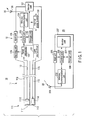
- a wireless image acquisition system includes an endoscope assembly 10, and an image receiving unit 20.
- the endoscope assembly 10 is an image acquisition apparatus for transmitting acquired image information by radio waves.
- the image receiving unit 20 receives and displays the image information transmitted from the endoscope assembly 10.
- the endoscope assembly 10 and image receiving unit 20 are shown only one each, but two or more can be used.
- the endoscope assembly 10 comprises an insertion part 11 to be inserted into a patient body cavity or path, and an operation unit 12 connected to the insertion part 11.
- the insertion part 11 is made of metallic material or flexible member.
- the inside of the insertion part 11 is divided into two parts, one is the image acquisition side, and the other is the light source side.
- the image acquisition side of the insertion part 11 is provided with an image acquisition unit 111 at the distal end.
- the image acquisition unit 111 comprises a camera lens 1111, and an image sensor 1112.
- the image sensor 1112 is a CCD, for example, which receives a optical image entered through the camera lens 1111, and converts it into an electric signal as image information.
- the electric signal from the image sensor 1112 is sent to an electric circuit of the operation unit 12 through a signal lead wire 112.
- the light source side of the insertion part 11 is provided with an illumination lens 113 at the distal end.
- a light source unit 114 is arranged in the rear of the illumination lens 113, and light from the light source unit 114 is applied to an observing part through the illumination lens 113.
- the light source unit 114 is composed of an LED or a lamp, and is connected to a light source driver 121 in the operation unit 12 through a lead wire 115.
- the operation unit 12 contains a signal converter 122, a control unit 123, a wireless communication unit 124, and a storage unit 125, in addition to the light source driver 121.
- the electric signal from the above image sensor 1112 is converted to a video signal by the signal converter 122.
- the video signal is sent to the wireless communication unit 124 through the control unit 123, and transmitted as a radio wave 30 from an antenna 126.
- the signal converter 122 is connected to a compact monitor unit 127 such as a liquid crystal monitor.
- the control unit 123 is connected to an input unit 128 and a warning unit 129.
- the input unit 128 is provided with switches, such as a power switch to instruct ON/OFF of power supply, and a freeze save switch to instruct saving of an observing image.
- the warning unit 129 includes an LED and a buzzer, for example.
- the storage unit 125 is a register to store communication setting information to be described later, and various information including image acquisition control information and additional information.
- the light source driver 121, signal converter 122, control unit 123, wireless communication unit 124, monitor unit 127, and warning unit 129 are connected to an internal power supply 130 such as a battery, and are driven with the power supply 130.
- the monitor unit 127 can be eliminated. It is possible to use an external power supply for driving the components, instead of the internal power supply 130. It is also possible to guide an illumination light from an external light source to the distal end of the insertion part 11, by providing a light guide as in a conventional endoscope assembly, instead of the light source unit 114, lead wire 115 and light source driver 121 in FIG. 1 .
- the light source unit can be provided in the operation unit 12, and a light guide can be provided to guide an illumination light to the distal end of the insertion part 11.
- the image sensor 1112 receives the light from the observing part.
- the signal converter 122 converts an optical image received by the image sensor 1112 into an electric video signal (image information), and transfers it to the control unit 123.
- the control unit 123 sends the image information to the wireless communication unit 124, by adding information such as switch information needed to sent to the receiving side.
- the wireless communication unit 124 converts the received information into a high-frequency signal, and transmits it as a radio wave 30 from the antenna 126.
- the radio wave 30 transmitted as described above is received by the image receiving unit 20.
- the image receiving unit 20 comprises an antenna 201, a wireless communication unit 202, a control unit 203, a monitor unit 204, an input unit 205, and a storage unit 206.
- the radio wave 30 received by the antenna 201 is sent to the wireless communication unit 202, in which the radio wave is demodulated to the original information.
- the demodulated information is sent to the control unit 203.
- the control unit 203 determines ON/OFF of the freeze saving switch according to the received information, and saves a freeze image to the storage unit 206, sends and displays an observing image to/in the monitor unit 204.
- the input unit 205 is a set of switches including a power supply switch.
- the storage unit 206 stores communication setting information, image acquisition control information, and additional information.
- a monitor apparatus may be connected to the image receiving unit 20 for displaying an image, instead of providing the monitor unit 204 in the image receiving unit 20.
- Radio waves are not necessarily be transmitted from the operation unit 12 of the endoscope assembly 10, and received by the image receiving unit 20. It is advantageous for reliability and expansion of functions to provide a function of transmitting radio waves from the image receiving unit 20 to the operation unit 12 for the purpose of confirming transmission and reception of data.
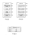
- the control unit 123 of the endoscope assembly 10 has an image acquisition controller 1231, a decoder 1232, a storage controller 1233, and a communication controller 1234.
- the image acquisition controller 1231 controls the image acquisition unit 111, which is not connected with a wire in the drawing. Specifically, the control includes brightness adjustment, and white balance adjustment.
- the decoder 1232 extracts communication setting information from an acquired image of a two-dimensional code.
- the storage controller 1233 stores the extracted communication setting information, image acquisition control information and additional information, in the storage unit 125.
- the communication controller 1234 receives communication data from the wireless communication unit 124, or sends communication data to the wireless communication unit 124.
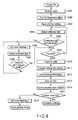
- the control unit 203 of the image receiving unit 20 has a code generator 2031, a display controller 2032, a storage controller 2033, and a communication controller 2034.
- the code generator 2031 generates a two-dimensional code storing communication setting information.
- the display controller 2032 displays the generated two-dimensional code on the monitor unit 204.
- the storage controller 2033 stores communication setting information, image acquisition control information and additional information, in the storage unit 206.
- the communication controller 2034 receives communication data from the wireless communication unit 202, or sends communication data to the wireless communication unit 202.
- the communication setting information stored in a two-dimensional code generated by the code generator 2031 includes channel setting, and a network ID.
- the communication controller 2034 obtains an already used channel from a radio wave received by the wireless communication unit 202 through the antenna 201, and identifies an unused channel.
- the communication controller 2034 sends the information about the identified channel to the storage controller 2033 as channel setting.
- the storage controller 2033 stores the information in the storage unit 206.
- the code generator 2031 reads communication setting information including the above channel information stored in the storage unit 206, and stores the information in a two-dimensional code.
- a SSID used in a wireless LAN is used as a network ID that is a recognition code of the image receiving unit 20.
- a SSID may be generated by generating a random number.
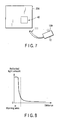
- An example of communication setting information is shown in FIG. 4 .
- the example in the drawing shows a case including encryption and communication mode. WEP is used as encryption. In the example shown in the drawing, WEP is OFF, but it may be ON.
- Encryption other than WEP is of course permitted (e.g. TKIP and AES).
- a communication mode (MODE) is set to use a 2.4 GHz band. But, another band, for example, 5 GHz may be used. WEP and MODE can be optionally set by the user.
- the control unit 203 obtains a SSID from the storage unit 206 by the storage controller 2033, or generates a SSID by generating a random number (step S101) FIG. 5 .
- the communication controller 2034 obtains an already used channel by using the wireless communication unit 202, thereby obtaining a usable channel, or an idle channel (step S102). Whether an idle channel exists or not is determined (step S103). When an idle channel does not exist, step S102 is resumed. Namely, an idle channel is waited.
- the code generator 2031 When existence of an idle channel is determined in step S103, the code generator 2031 generates a two-dimensional code (step S104).
- the display controller 2032 displays the generated two-dimensional code in the monitor unit 204 (step S105).
- a position to display the two-dimensional code is optional, but desirably a position easy to be captured by the endoscope assembly 10.
- a two-dimensional code 40 is displayed in the lower right of the display screen of the monitor unit 204.
- the communication controller 2034 checks whether a communication start request is received from the endoscope assembly 10, by the wireless communication unit 202, and determines whether a communication start request is received or not (step S106). When a communication start request is not received, step S105 is resumed. Namely, a communication start request is waited.
- control unit 123 checks the battery power, and goes to a setting mode FIG. 6 (step S201).
- the image acquisition controller 1231 controls the light source driver 121, and turns on the light source 114 to emit light (step S202).
- the LED of the warning unit 129 flashes at predetermined intervals as a warning of communication setting (step S203).
- the two-dimensional code 40 displayed on the monitor unit 204 is captured.
- the light generated by driving the light source unit 114 is intermittently emitted through the illumination lens 113.
- the emitted light is reflected on the display screen surface of the monitor unit 204, and is partially applied to the image acquisition unit 111 as a reflected light.
- the image acquisition unit 111 obtains the amount of the reflected light by analog-to-digital conversion (step S204), and determines whether the amount is larger than a predetermined value (step S205).
- the reflected light amount varies depending on the distance from the image acquisition unit 111 to the display screen surface of the monitor unit 204 as shown in FIG. 8 .
- the distance is within a predetermined value, that is, the distance is too close.
- the LED of the warning unit 129 flashes in a pattern indicating the extremely close distance, thereby warning the user that the distal end of the imaging pickup unit 111 is too close to the display screen surface of the monitor unit 204 (step S206).
- the distance may be determined by a relative amount of reflected light, based on a case in which the distance from the image acquisition unit 111 to the display screen surface of the monitor unit 204 is sufficiently separated, and there is no reflected light.
- the reflected light amount is obtained again in the image acquisition unit 111 by analog-to-digital conversion (step S207), and whether the reflected light amount is smaller than the predetermined value is determined (step S208). If the reflected light amount is not smaller than the predetermined value, step S206 is resumed, and a warning is continued.
- step S209 When the reflected light amount is determined to be smaller than the predetermined value in step S205 or S208, whether focus is achieved is determined (step S209). Whether focus is achieved is determined by using a general contrast method. If focus is not achieved on the two-dimensional code 40 displayed on the monitor unit 204, step S204 is resumed.
- the image acquisition unit 111 captures the two-dimensional code 40 by controlling of the image acquisition controller 1231 (step S210).
- the decoder 1232 decodes the code from the acquired image information of the two-dimensional code 40, and extracts communication setting information (step S211).
- the storage unit 125 stores the extracted communication setting information by controlling of the storage controller 1233 (step S212).
- the LED of the warning unit 129 is continuously lit, thereby notifying the user of the completion of setting (step S213).
- the completion of setting may be notified to the user by the LED of the warning unit 129, when communication setting information is extracted, a two-dimensional code is recognized, or focus is achieved, other than the timing when the storing of communication setting information is completed.
- the wireless communication unit 124 transmits a communication start request by controlling of the communication controller 1234, based on the communication setting information stored in the storage unit 125 (step S214).
- the control unit 203 determines whether the wireless communication unit 202 receives the communication start request by controlling of the communication controller 2034, in step S106.
- the setting values of the received communication setting information and the communication setting information stored in the storage unit 206 are compared (step S107).
- the contents of the communication setting information generated by the image receiving unit 20 are the same as the contents of communication setting information decoded by the endoscope assembly 10 and transmitted by a communication start request. Therefore, if the result of the comparison is not the same, the display controller 2032 displays a setting error on the monitor unit 204 (step S108), and step S102 is resumed.
- the wireless communication unit 202 returns a response by controlling of the communication controller 2034, as a notice to indicate completion of communication setting (step S109).
- the control unit 123 determines whether the wireless communication unit 124 returns the response by the communication controller 1234 (step S215). If the response is not returned, the LED of the warning unit 129 flashes in a pattern to indicate a failure in starting communication (step S216), and the setting mode is finished. When the return of response is confirmed, communication is started. Namely, as described above, the contents of the communication setting information generated by the image receiving unit 20 are the same as the contents of communication setting information decoded by the endoscope assembly 10, and communication is possible between the image receiving unit 20 and endoscope assembly 10. When the communication setting is completed, the endoscope assembly 10 is shifted to an observation mode.
- an image acquired by the image acquisition unit 111 of the endoscope assembly 10 is transmitted to the wireless communication unit 124 by the radio wave 30, received by the antenna 201 of the image receiving unit 20, and subjected to a predetermined image processing.
- the resultant image is displayed on the monitor unit 204.
- the image acquisition unit 111 of the endoscope assembly 10 can be brought unnecessarily close to the monitor unit 204, and they are prevented from contacting. Therefore, even if two or more same type endoscope assembly 10 are provided in adjacent places, a user can cleanly, securely and easily start communication between the endoscope assembly 10 at hand and the image receiving unit 20 right before.
- the insertion part 11 that is a part to be inserted into a patient contacts the monitor unit 204 that is an unclean part, and the insertion part 11 can be kept clean. This is particularly effective for the endoscope assembly 10.
- the endoscope assembly 10 detects that the distance from the image acquisition unit 111 to the monitor unit 204 of the image receiving unit 20 is within a predetermined value, the hardware provided in the endoscope assembly 10 can be effectively used. As the warning unit 129 is provided in the endoscope assembly 10, it is unnecessary to add specific hardware and software to the image receiving unit 20.
- the distance can be easily detected by effectively using the hardware provided in the endoscope assembly 10, such as the illumination lens 113, light source unit 114, camera lens 1111, and image sensor 1112.
- the endoscope assembly 10 can specify the image receiving unit 20, and sets a channel to be used.
- a warning by the warning unit 129 may be an audible beep tone by a buzzer, or may be combined with an LED.
- a two-dimensional code may be fixed to each image receiving unit 20, and be stuck to the housing 207 of the image receiving unit 20 as a two-dimensional code label 41, as shown in FIG. 9 .
- the two-dimensional code 40 is displayed on the monitor unit 204.
- the display unit 208 dedicated to a two-dimensional code is provided in the housing 207 of the image receiving unit 20.
- the display unit 208 dedicated to a two-dimensional code comprises a well 209 formed in the housing 207, a display unit 210, and a scope guide 211, as shown in FIG. 11 .
- the display unit 210 is a part to display the two-dimensional code 40 arranged at the bottom of the well 209.
- the scope guide 211 is removably fit in the well 209.
- the image acquisition unit 111 of the endoscope assembly 10 is inserted into the scope guide 211.
- the scope guide 211 is configured to define the distal end position of the image acquisition unit 111 so that the distance from the distal end of the inserted image acquisition unit 111 to the display unit 210 reaches a focused distance f.
- the endoscope assembly 10 and image receiving unit 20 in the setting mode are completely set simply by inserting the image acquisition unit 111 of the endoscope assembly 10 into the display unit 208 dedicated to a two-dimensional code.
- the scope guide 211 of the display unit 208 dedicated to a two-dimensional code can be removed and cleaned by a cleaner to keep cleanness.
- a focal position does not fluctuate with setting conditions when a two-dimensional code is captured. This facilitates the setting.
- the display unit 210 may be arranged on the surface of the housing 207 of the image receiving unit 20, and a projection to insert the scope guide 211 may be provided, rather than providing the display unit 210 to display a two-dimensional code at the bottom of the well 209.
- the display unit 210 may be arranged on the surface of the housing 207 of the image receiving unit 20.
- a guide cap to be fit to the image acquisition unit 111 of the endoscope assembly 10 is used instead of the scope guide 211.
- the guide cap may be configured to set the image acquisition unit 111 at a focal position in the state in which the distal end surface of the guide cap contacts the display unit 210.
- the embodiments are explained as an example of a wireless image acquisition system including the endoscope assembly 10 and image receiving unit 20.
- the invention is also applicable to any wireless image acquisition system, as long as it includes an image acquisition apparatus which transmits acquired image information by radio waves, and an image receiving unit which receives and displays the image information transmitted from the image acquisition apparatus.
- the distance from the endoscope assembly 10, which is an image acquisition apparatus, to the image receiving unit 20 is detected and warned by the image acquisition apparatus.
- the distance may be detected and warned by emitting light or radio wave from the image receiving unit.
- a warning unit may be provided in the image receiving unit 20, and a warning display easily appears in the field of view of a user who watches his (her) hand to bring the image acquisition unit 111 of the image acquisition apparatus, close to the monitor unit 204 of the image receiving unit 20.
- wireless communication setting information is presented as a two-dimensional code in the image receiving unit, and is captured and encoded by the image acquisition apparatus.
- the code is not limited to two-dimensional, and one-dimensional code may be used.
- text information may be presented by giving the image acquisition apparatus a character recognition function.
Landscapes
- Life Sciences & Earth Sciences (AREA)
- Health & Medical Sciences (AREA)
- Surgery (AREA)
- Engineering & Computer Science (AREA)
- Biophysics (AREA)
- Public Health (AREA)
- Veterinary Medicine (AREA)
- Physics & Mathematics (AREA)
- Pathology (AREA)
- General Health & Medical Sciences (AREA)
- Animal Behavior & Ethology (AREA)
- Biomedical Technology (AREA)
- Heart & Thoracic Surgery (AREA)
- Medical Informatics (AREA)
- Molecular Biology (AREA)
- Radiology & Medical Imaging (AREA)
- Optics & Photonics (AREA)
- Nuclear Medicine, Radiotherapy & Molecular Imaging (AREA)
- Signal Processing (AREA)
- Computer Networks & Wireless Communication (AREA)
- Multimedia (AREA)
- Endoscopes (AREA)
- Instruments For Viewing The Inside Of Hollow Bodies (AREA)
Abstract
A wireless image acquisition system includes an endoscope assembly (10) for transmitting acquired image information by radio waves, and an image receiving unit (20) for receiving and display the image information transmitted from the endoscope assembly (10). A monitor unit (204) of the image receiving unit (20) displays wireless communication setting information. An image acquisition unit (111) of the endoscope assembly (10) captures the wireless communication setting information. A control unit (123) of the endoscope assembly (10) makes wireless communication setting of the endoscope assembly (10) based on the captured wireless communication setting information, and detect that the distance from the image acquisition unit (111) to the monitor unit (204) is within a predetermined value when the wireless communication setting information is captured. A warning unit (129) of the endoscope assembly (10) gives a warning when the detected distance is within the predetermined value.
Description
- The present invention relates to a wireless image acquisition system, which transmits acquired image information to an image receiving unit by radio waves.
- In recent years, there has been widely used an endoscope system which can observe an image of a subject in an abdominal cavity or path by inserting a slender insertion tube part into an abdominal cavity or path.
- Such an endoscope system generally comprises an endoscope assembly, a light source unit, a light guide cable, an image acquisition unit, a video processor, a signal cable, and a monitor unit. The endoscope assembly has an insertion tube part, which is inserted into an abdominal cavity or path. The light source unit is provided separately from the endoscope assembly, and supplies an illumination light to the endoscope assembly. The light guide cable leads the illumination light from the light source unit to the endoscope assembly. The image acquisition unit is built in or removably provided in the endoscope assembly, and captures a subject and obtains its image data. The video processor is provided separately from the endoscope assembly, and converts the image data obtained by the endoscope assembly into a video signal displayable on a monitor. The signal cable is used to transmit the image data from the endoscope assembly to the video processor. The monitor unit displays the video signal obtained by the video processor. Therefore, the endoscope assembly is connected to the light source unit and video processor, which are external units, through the light guide cable and the signal cable. This limits a movable range of the endoscope assembly, and disturbs the operability of the endoscope assembly.
- Under the circumstances,
U.S. Patent No. 4,633,304 discloses the following endoscope system. In this endoscope system, an illumination unit comprising a light-emitting diode (LED) is incorporated in an endoscope assembly. Thereby, a light guide cable extended from an endoscope assembly is eliminated. The endoscope assembly is provided with a video signal processing circuit, which obtains a video signal displayable on a monitor by processing image data, and a transmission circuit, which transmits the video signal by radio waves. A data processing unit, which receives the radio waves from the transmission circuit, and demodulates the video signal, is provided separately from the endoscope assembly. Thereby, a signal cable extended from the endoscope assembly is eliminated. Such an endoscope system is generally called a wireless endoscope system, and has advantages that a movable range of the endoscope assembly is not limited, and the operability of the endoscope assembly is improved. - As another example of a wireless endoscope system, Jpn. Pat. Appln. KOKAI Publication No.
2004-266628
Further, Jpn. Pat. Appln. KOKAI Publication Nos.2006-271432 2006-271433 2004-266628 2006-271432 2006-271433 - To solve the above problem, Jpn. Pat. Appln. KOKAI Publication No.
2006-261938 - However, the following problem occurs when two or more conventional wireless endoscope systems disclosed in the above
U.S. Patent No. 4,633,304 are used at close range. - There are two or more endoscopic diagnosis rooms in a large-scale hospital. Each diagnosis room has an image receiving unit provided with a monitor unit or connected to a monitor apparatus. An insertion part of an endoscope assembly is inserted into a patient's body cavity or path, and is visually inspected on a monitor unit or apparatus of an image receiving unit. In such a case, it is assumed that there are three diagnosis rooms and an endoscopic image receiving unit is provided in each room. These diagnosis rooms are located nearby in many cases, or merely parted by a curtain. Thus, radio communication may be possible between first and third diagnosis rooms. However, a user demands to watch an image of an endoscope assembly at hand, by a monitor unit of an image receiving unit installed in a room, or by a monitor apparatus connected to the image receiving unit.
- Further, an endoscope assembly including an insertion part needs to be cleaned after the inspection by inserting into a patient is finished. An endoscope assembly is often cleaned in another room separated from a diagnosis room, and is carried out of a diagnosis room. The endoscope assembly is not necessarily returned to its original room after cleaning, and is desired to return preferentially to a diagnosis room prepared for the next diagnosis. In addition, two or more endoscope assemblies with different insertion part lengths may be prepared depending on purposes, and a user demands to select an appropriate one and use it in a diagnosis room. From this point of view, the user wants to freely change combination of an endoscope assembly and an image receiving unit.
- As described above, combination of an endoscope assembly and an image receiving unit may be changed, and a user demands to easily start communication between an endoscope assembly at hand and an image receiving unit right before.
- In a conventional wired connection, if shapes and signal contents of a connector to connect a cable are unified or interchangeable, an endoscope assembly and an image receiving unit can be combined in a desired pattern simply by connecting a cable, and no problem arises.
- In contrast, as described above, when an endoscope assembly and an image receiving unit communicate with each other by radio waves, an endoscope assembly may communicate with image receiving units provided in adjacent diagnosis rooms by radio waves. Because, it is difficult to determine with which image receiving unit is to communicate, by an arithmetic operation in an endoscope assembly. There is an idea to identify an object image receiving unit by the intensity of radio wave, but the distance and signal intensity between opposing endoscope assembly and image receiving unit are not exactly correlated due to the direction of antennas or obstacles between the endoscope assembly and image receiving unit, and correct determination is difficult. Therefore, this idea is not practical.
- In the method of obtaining communication parameters proposed in the patent application No.
2006-261938 , safety as a medical apparatus is not considered, and this method cannot be applied to a wireless endoscope system. Namely, an endoscope assembly does not generally have a display, and whether two-dimensional codes are read or not is not determined, until communication setting is completed and an image is displayed on a monitor unit of an image receiving unit or on a monitor apparatus connected to an image receiving unit. Therefore, in a period from setting to start of communication, an endoscope assembly must be held close to a two-dimensional code display unit, for example, a monitor unit of an image receiving unit or a monitor apparatus connected to an image receiving unit. This may bring an image acquisition unit, which is provided at a distal end of an insertion part of an endoscope assembly and is inserted into a patient' body, into contact with a monitor unit or a monitor apparatus, which is an unclean part. - The present invention has been made in the above circumstances. It is an object of the invention to provide a wireless image acquisition system, which is configured to securely, easily and cleanly start communication between an image acquisition apparatus at hand and an image receiving unit right before, even if two or more same type image acquisition apparatuses are provided in adjacent places.
- According to one aspect of the invention, there is provided a wireless image acquisition system including an image acquisition apparatus for transmitting acquired image information by radio waves, and an image receiving unit for receiving and displaying the image information transmitted from the image acquisition apparatus, comprising:
- display means, which is provided in the image receiving unit, for displaying wireless communication setting information required by the image acquisition apparatus for making communication with the image receiving unit;
- image acquisition means, which is provided in the image acquisition apparatus, for capturing the wireless communication setting information displayed on the display means; and
- communication setting means, which is provided in the image acquisition apparatus, for making wireless communication setting of the image acquisition apparatus, based on the wireless communication setting information captured by the image acquisition means, characterized by further comprising:
- detection means, which is provided in one of the image acquisition apparatus and image receiving unit, for detecting that the distance from the image acquisition means to the display means is within a predetermined value when the wireless communication setting information is captured; and
- warning means, which is provided in one of the image acquisition apparatus and image receiving unit, for giving a warning when the detection means detects that the distance from the image acquisition means to the display means is within the predetermined value.
- The invention can be more fully understood from the following detailed description when taken in conjunction with the accompanying drawings, in which:
-
FIG. 1 is a block diagram showing a configuration of a wireless image acquisition system according to a first embodiment of the invention; -
FIG. 2 is a diagram showing a configuration of a control unit of an endoscope assembly; -
FIG. 3 is a diagram showing a configuration of a control unit of an image receiving unit; -
FIG. 4 is a diagram showing an example of parameters to be stored in a two-dimensional code; -
FIG. 5 is a flowchart for explaining a setting operation in an image receiving unit; -
FIG. 6 is a flowchart for explaining a setting operation in an endoscope assembly; -
FIG. 7 is a diagram showing a relationship between an endoscope assembly and an image receiving unit, when a two-dimensional code is displayed; -
FIG. 8 is a graph showing a relationship between the amount of reflected light and distance; -
FIG. 9 is a diagram showing a case in which a two-dimensional code is labeled on a housing of an image receiving unit; -
FIG. 10 is a diagram showing a configuration of an image receiving unit in a wireless image acquisition system according to a second embodiment of the invention; and -
FIG. 11 is a sectional view showing a configuration of a display unit dedicated to a two-dimensional code. - Hereinafter, a best mode for embodying the invention will be explained with reference to the accompanying drawings.
- As shown in
FIG. 1 , a wireless image acquisition system according to a first embodiment of the invention includes anendoscope assembly 10, and an image receiving unit 20. Theendoscope assembly 10 is an image acquisition apparatus for transmitting acquired image information by radio waves. The image receiving unit 20 receives and displays the image information transmitted from theendoscope assembly 10. InFIG. 1 , theendoscope assembly 10 and image receiving unit 20 are shown only one each, but two or more can be used. - The
endoscope assembly 10 comprises aninsertion part 11 to be inserted into a patient body cavity or path, and anoperation unit 12 connected to theinsertion part 11. - The
insertion part 11 is made of metallic material or flexible member. The inside of theinsertion part 11 is divided into two parts, one is the image acquisition side, and the other is the light source side. The image acquisition side of theinsertion part 11 is provided with animage acquisition unit 111 at the distal end. Theimage acquisition unit 111 comprises acamera lens 1111, and animage sensor 1112. Theimage sensor 1112 is a CCD, for example, which receives a optical image entered through thecamera lens 1111, and converts it into an electric signal as image information. The electric signal from theimage sensor 1112 is sent to an electric circuit of theoperation unit 12 through asignal lead wire 112. The light source side of theinsertion part 11 is provided with anillumination lens 113 at the distal end. Alight source unit 114 is arranged in the rear of theillumination lens 113, and light from thelight source unit 114 is applied to an observing part through theillumination lens 113. Thelight source unit 114 is composed of an LED or a lamp, and is connected to alight source driver 121 in theoperation unit 12 through alead wire 115. - The
operation unit 12 contains asignal converter 122, acontrol unit 123, awireless communication unit 124, and astorage unit 125, in addition to thelight source driver 121. The electric signal from theabove image sensor 1112 is converted to a video signal by thesignal converter 122. The video signal is sent to thewireless communication unit 124 through thecontrol unit 123, and transmitted as aradio wave 30 from anantenna 126. Thesignal converter 122 is connected to acompact monitor unit 127 such as a liquid crystal monitor. Thecontrol unit 123 is connected to aninput unit 128 and awarning unit 129. Theinput unit 128 is provided with switches, such as a power switch to instruct ON/OFF of power supply, and a freeze save switch to instruct saving of an observing image. Thewarning unit 129 includes an LED and a buzzer, for example. Thestorage unit 125 is a register to store communication setting information to be described later, and various information including image acquisition control information and additional information. - The
light source driver 121,signal converter 122,control unit 123,wireless communication unit 124,monitor unit 127, andwarning unit 129 are connected to aninternal power supply 130 such as a battery, and are driven with thepower supply 130. - The
monitor unit 127 can be eliminated. It is possible to use an external power supply for driving the components, instead of theinternal power supply 130. It is also possible to guide an illumination light from an external light source to the distal end of theinsertion part 11, by providing a light guide as in a conventional endoscope assembly, instead of thelight source unit 114,lead wire 115 andlight source driver 121 inFIG. 1 . The light source unit can be provided in theoperation unit 12, and a light guide can be provided to guide an illumination light to the distal end of theinsertion part 11. - In the
endoscope assembly 10 configured as described above, when theinsertion part 11 is inserted into a patient's body cavity or path, and thelight source unit 114 emits light to an observing part, theimage sensor 1112 receives the light from the observing part. Thesignal converter 122 converts an optical image received by theimage sensor 1112 into an electric video signal (image information), and transfers it to thecontrol unit 123. Thecontrol unit 123 sends the image information to thewireless communication unit 124, by adding information such as switch information needed to sent to the receiving side. Thewireless communication unit 124 converts the received information into a high-frequency signal, and transmits it as aradio wave 30 from theantenna 126. - The
radio wave 30 transmitted as described above is received by the image receiving unit 20. The image receiving unit 20 comprises anantenna 201, awireless communication unit 202, acontrol unit 203, amonitor unit 204, aninput unit 205, and astorage unit 206. Theradio wave 30 received by theantenna 201 is sent to thewireless communication unit 202, in which the radio wave is demodulated to the original information. The demodulated information is sent to thecontrol unit 203. Thecontrol unit 203 determines ON/OFF of the freeze saving switch according to the received information, and saves a freeze image to thestorage unit 206, sends and displays an observing image to/in themonitor unit 204. Theinput unit 205 is a set of switches including a power supply switch. Thestorage unit 206 stores communication setting information, image acquisition control information, and additional information. - A monitor apparatus may be connected to the image receiving unit 20 for displaying an image, instead of providing the
monitor unit 204 in the image receiving unit 20. - Radio waves are not necessarily be transmitted from the
operation unit 12 of theendoscope assembly 10, and received by the image receiving unit 20. It is advantageous for reliability and expansion of functions to provide a function of transmitting radio waves from the image receiving unit 20 to theoperation unit 12 for the purpose of confirming transmission and reception of data. - As shown in
FIG. 2 , thecontrol unit 123 of theendoscope assembly 10 has animage acquisition controller 1231, adecoder 1232, astorage controller 1233, and acommunication controller 1234. Theimage acquisition controller 1231 controls theimage acquisition unit 111, which is not connected with a wire in the drawing. Specifically, the control includes brightness adjustment, and white balance adjustment. Thedecoder 1232 extracts communication setting information from an acquired image of a two-dimensional code. Thestorage controller 1233 stores the extracted communication setting information, image acquisition control information and additional information, in thestorage unit 125. Thecommunication controller 1234 receives communication data from thewireless communication unit 124, or sends communication data to thewireless communication unit 124. - As shown in
FIG. 3 , thecontrol unit 203 of the image receiving unit 20 has acode generator 2031, adisplay controller 2032, astorage controller 2033, and acommunication controller 2034. Thecode generator 2031 generates a two-dimensional code storing communication setting information. Thedisplay controller 2032 displays the generated two-dimensional code on themonitor unit 204. Thestorage controller 2033 stores communication setting information, image acquisition control information and additional information, in thestorage unit 206. Thecommunication controller 2034 receives communication data from thewireless communication unit 202, or sends communication data to thewireless communication unit 202. - The communication setting information stored in a two-dimensional code generated by the
code generator 2031 includes channel setting, and a network ID. Thecommunication controller 2034 obtains an already used channel from a radio wave received by thewireless communication unit 202 through theantenna 201, and identifies an unused channel. Thecommunication controller 2034 sends the information about the identified channel to thestorage controller 2033 as channel setting. Thestorage controller 2033 stores the information in thestorage unit 206. Thecode generator 2031 reads communication setting information including the above channel information stored in thestorage unit 206, and stores the information in a two-dimensional code. - In this embodiment, a SSID used in a wireless LAN, for example, is used as a network ID that is a recognition code of the image receiving unit 20. The
endoscope assembly 10 is designed to be able to communicate with a specific unit only, such as an image receiving unit 20, and a part of the SSID is fixed (e.g. SSID = [ABCD_UNIT_****], the "*" part is a serial number given for each image receiving unit 20). A SSID may be generated by generating a random number. An example of communication setting information is shown inFIG. 4 . The example in the drawing shows a case including encryption and communication mode. WEP is used as encryption. In the example shown in the drawing, WEP is OFF, but it may be ON. Encryption other than WEP is of course permitted (e.g. TKIP and AES). A communication mode (MODE) is set to use a 2.4 GHz band. But, another band, for example, 5 GHz may be used. WEP and MODE can be optionally set by the user. - Next, an explanation will be given of the operation of the wireless image acquisition system configured as described above, by referring to
FIGS. 5 and6 . - As shown in
FIG. 5 , when the power supply of the image receiving unit 20 is turned on, thecontrol unit 203 obtains a SSID from thestorage unit 206 by thestorage controller 2033, or generates a SSID by generating a random number (step S101)FIG. 5 . Thecommunication controller 2034 obtains an already used channel by using thewireless communication unit 202, thereby obtaining a usable channel, or an idle channel (step S102). Whether an idle channel exists or not is determined (step S103). When an idle channel does not exist, step S102 is resumed. Namely, an idle channel is waited. - When existence of an idle channel is determined in step S103, the
code generator 2031 generates a two-dimensional code (step S104). Thedisplay controller 2032 displays the generated two-dimensional code in the monitor unit 204 (step S105). A position to display the two-dimensional code is optional, but desirably a position easy to be captured by theendoscope assembly 10. In this embodiment, as shown inFIG. 7 , a two-dimensional code 40 is displayed in the lower right of the display screen of themonitor unit 204. - Thereafter, the
communication controller 2034 checks whether a communication start request is received from theendoscope assembly 10, by thewireless communication unit 202, and determines whether a communication start request is received or not (step S106). When a communication start request is not received, step S105 is resumed. Namely, a communication start request is waited. - As shown in
FIG. 6 , when the power supply of theendoscope assembly 10 is turned off, thecontrol unit 123 checks the battery power, and goes to a setting modeFIG. 6 (step S201). - In the setting mode, the
image acquisition controller 1231 controls thelight source driver 121, and turns on thelight source 114 to emit light (step S202). The LED of thewarning unit 129 flashes at predetermined intervals as a warning of communication setting (step S203). By bringing theimage acquisition unit 111 close to themonitor unit 204 of the image receiving unit 20 in this setting mode, the two-dimensional code 40 displayed on themonitor unit 204 is captured. In this time, the light generated by driving thelight source unit 114 is intermittently emitted through theillumination lens 113. The emitted light is reflected on the display screen surface of themonitor unit 204, and is partially applied to theimage acquisition unit 111 as a reflected light. Theimage acquisition unit 111 obtains the amount of the reflected light by analog-to-digital conversion (step S204), and determines whether the amount is larger than a predetermined value (step S205). The reflected light amount varies depending on the distance from theimage acquisition unit 111 to the display screen surface of themonitor unit 204 as shown inFIG. 8 . - Therefore, when the reflected light amount is larger than a predetermined value, the distance is within a predetermined value, that is, the distance is too close. In such a case, the LED of the
warning unit 129 flashes in a pattern indicating the extremely close distance, thereby warning the user that the distal end of theimaging pickup unit 111 is too close to the display screen surface of the monitor unit 204 (step S206). The distance may be determined by a relative amount of reflected light, based on a case in which the distance from theimage acquisition unit 111 to the display screen surface of themonitor unit 204 is sufficiently separated, and there is no reflected light. The reflected light amount is obtained again in theimage acquisition unit 111 by analog-to-digital conversion (step S207), and whether the reflected light amount is smaller than the predetermined value is determined (step S208). If the reflected light amount is not smaller than the predetermined value, step S206 is resumed, and a warning is continued. - When the reflected light amount is determined to be smaller than the predetermined value in step S205 or S208, whether focus is achieved is determined (step S209). Whether focus is achieved is determined by using a general contrast method. If focus is not achieved on the two-
dimensional code 40 displayed on themonitor unit 204, step S204 is resumed. - In contrast, when focus is achieved on the two-
dimensional code 40 displayed on themonitor unit 204, theimage acquisition unit 111 captures the two-dimensional code 40 by controlling of the image acquisition controller 1231 (step S210). Thedecoder 1232 decodes the code from the acquired image information of the two-dimensional code 40, and extracts communication setting information (step S211). Thestorage unit 125 stores the extracted communication setting information by controlling of the storage controller 1233 (step S212). When the storing of the communication setting information is completed, the LED of thewarning unit 129 is continuously lit, thereby notifying the user of the completion of setting (step S213). The completion of setting may be notified to the user by the LED of thewarning unit 129, when communication setting information is extracted, a two-dimensional code is recognized, or focus is achieved, other than the timing when the storing of communication setting information is completed. - Thereafter, the
wireless communication unit 124 transmits a communication start request by controlling of thecommunication controller 1234, based on the communication setting information stored in the storage unit 125 (step S214). - As shown in
FIG. 5 , in the image receiving unit 20, thecontrol unit 203 determines whether thewireless communication unit 202 receives the communication start request by controlling of thecommunication controller 2034, in step S106. When reception of the communication start request is confirmed, the setting values of the received communication setting information and the communication setting information stored in thestorage unit 206 are compared (step S107). The contents of the communication setting information generated by the image receiving unit 20 are the same as the contents of communication setting information decoded by theendoscope assembly 10 and transmitted by a communication start request. Therefore, if the result of the comparison is not the same, thedisplay controller 2032 displays a setting error on the monitor unit 204 (step S108), and step S102 is resumed. When the result of the comparison is the same, thewireless communication unit 202 returns a response by controlling of thecommunication controller 2034, as a notice to indicate completion of communication setting (step S109). - As shown in
FIG. 6 , in theendoscope assembly 10, thecontrol unit 123 determines whether thewireless communication unit 124 returns the response by the communication controller 1234 (step S215). If the response is not returned, the LED of thewarning unit 129 flashes in a pattern to indicate a failure in starting communication (step S216), and the setting mode is finished. When the return of response is confirmed, communication is started. Namely, as described above, the contents of the communication setting information generated by the image receiving unit 20 are the same as the contents of communication setting information decoded by theendoscope assembly 10, and communication is possible between the image receiving unit 20 andendoscope assembly 10. When the communication setting is completed, theendoscope assembly 10 is shifted to an observation mode. Therefore, an image acquired by theimage acquisition unit 111 of theendoscope assembly 10 is transmitted to thewireless communication unit 124 by theradio wave 30, received by theantenna 201 of the image receiving unit 20, and subjected to a predetermined image processing. The resultant image is displayed on themonitor unit 204. - It is also possible to display a message to state that the setting is completed or failed, in the
monitor unit 204 of the image receiving unit 20, when the communication setting is competed or failed. - As described above, according to the first embodiment, the
image acquisition unit 111 of theendoscope assembly 10 can be brought unnecessarily close to themonitor unit 204, and they are prevented from contacting. Therefore, even if two or more sametype endoscope assembly 10 are provided in adjacent places, a user can cleanly, securely and easily start communication between theendoscope assembly 10 at hand and the image receiving unit 20 right before. - Besides, there is no possibility that the
insertion part 11 that is a part to be inserted into a patient contacts themonitor unit 204 that is an unclean part, and theinsertion part 11 can be kept clean. This is particularly effective for theendoscope assembly 10. - Further, as the
endoscope assembly 10 detects that the distance from theimage acquisition unit 111 to themonitor unit 204 of the image receiving unit 20 is within a predetermined value, the hardware provided in theendoscope assembly 10 can be effectively used. As thewarning unit 129 is provided in theendoscope assembly 10, it is unnecessary to add specific hardware and software to the image receiving unit 20. - The distance can be easily detected by effectively using the hardware provided in the
endoscope assembly 10, such as theillumination lens 113,light source unit 114,camera lens 1111, andimage sensor 1112. - The
endoscope assembly 10 can specify the image receiving unit 20, and sets a channel to be used. - A warning by the
warning unit 129 may be an audible beep tone by a buzzer, or may be combined with an LED. - A two-dimensional code may be fixed to each image receiving unit 20, and be stuck to the
housing 207 of the image receiving unit 20 as a two-dimensional code label 41, as shown inFIG. 9 . - Next, a second embodiment of the invention will be explained. In the first embodiment, the two-
dimensional code 40 is displayed on themonitor unit 204. In the second embodiment, as shown inFIG. 10 , thedisplay unit 208 dedicated to a two-dimensional code is provided in thehousing 207 of the image receiving unit 20. - The
display unit 208 dedicated to a two-dimensional code comprises a well 209 formed in thehousing 207, adisplay unit 210, and ascope guide 211, as shown inFIG. 11 . Thedisplay unit 210 is a part to display the two-dimensional code 40 arranged at the bottom of thewell 209. Thescope guide 211 is removably fit in thewell 209. Theimage acquisition unit 111 of theendoscope assembly 10 is inserted into thescope guide 211. Thescope guide 211 is configured to define the distal end position of theimage acquisition unit 111 so that the distance from the distal end of the insertedimage acquisition unit 111 to thedisplay unit 210 reaches a focused distance f. - Therefore, the
endoscope assembly 10 and image receiving unit 20 in the setting mode are completely set simply by inserting theimage acquisition unit 111 of theendoscope assembly 10 into thedisplay unit 208 dedicated to a two-dimensional code. - The
scope guide 211 of thedisplay unit 208 dedicated to a two-dimensional code can be removed and cleaned by a cleaner to keep cleanness. - As described above, according to the second embodiment, a focal position does not fluctuate with setting conditions when a two-dimensional code is captured. This facilitates the setting.
- As the
display unit 208 dedicated to a two-dimensional code, thedisplay unit 210 may be arranged on the surface of thehousing 207 of the image receiving unit 20, and a projection to insert thescope guide 211 may be provided, rather than providing thedisplay unit 210 to display a two-dimensional code at the bottom of thewell 209. - Alternatively, the
display unit 210 may be arranged on the surface of thehousing 207 of the image receiving unit 20. In this case, a guide cap to be fit to theimage acquisition unit 111 of theendoscope assembly 10 is used instead of thescope guide 211. The guide cap may be configured to set theimage acquisition unit 111 at a focal position in the state in which the distal end surface of the guide cap contacts thedisplay unit 210. - The invention is explained herein based on the embodiments. The invention is not limited to the embodiments. The invention may be modified or applied in various forms without departing from its spirit or essential characteristics.
- For example, the embodiments are explained as an example of a wireless image acquisition system including the
endoscope assembly 10 and image receiving unit 20. The invention is also applicable to any wireless image acquisition system, as long as it includes an image acquisition apparatus which transmits acquired image information by radio waves, and an image receiving unit which receives and displays the image information transmitted from the image acquisition apparatus. - Further, in the embodiments, the distance from the
endoscope assembly 10, which is an image acquisition apparatus, to the image receiving unit 20 is detected and warned by the image acquisition apparatus. The distance may be detected and warned by emitting light or radio wave from the image receiving unit. In this case, a warning unit may be provided in the image receiving unit 20, and a warning display easily appears in the field of view of a user who watches his (her) hand to bring theimage acquisition unit 111 of the image acquisition apparatus, close to themonitor unit 204 of the image receiving unit 20. - Further, in the embodiments, wireless communication setting information is presented as a two-dimensional code in the image receiving unit, and is captured and encoded by the image acquisition apparatus. However, the code is not limited to two-dimensional, and one-dimensional code may be used. Alternatively, text information may be presented by giving the image acquisition apparatus a character recognition function.
Claims (5)
- A wireless image acquisition system including an image acquisition apparatus (10) for transmitting acquired image information by radio waves, and an image receiving unit (20) for receiving and displaying the image information transmitted from the image acquisition apparatus, comprising:display means (204), which is provided in the image receiving unit, for displaying wireless communication setting information required by the image acquisition apparatus for making communication with the image receiving unit;image acquisition means (111), which is provided in the image acquisition apparatus, for capturing the wireless communication setting information displayed on the display means; andcommunication setting means (123), which is provided in the image acquisition apparatus, for making wireless communication setting of the image acquisition apparatus, based on the wireless communication setting information captured by the image acquisition means, characterized by further comprising:detection means (123), which is provided in one of the image acquisition apparatus and image receiving unit, for detecting that the distance from the image acquisition means to the display means is within a predetermined value when the wireless communication setting information is captured; andwarning means (129), which is provided in one of the image acquisition apparatus and image receiving unit, for giving a warning when the detection means detects that the distance from the image acquisition means to the display means is within the predetermined value.
- The wireless image acquisition system according to claim 1, characterized in that
the image acquisition apparatus includes an endoscope assembly, and
the image acquisition means is provided in an insertion part (11) which is inserted into a patient body. - The wireless image acquisition system according to claim 2, characterized in that at least one of the detection means and warning means is provided in the image acquisition apparatus.
- The wireless image acquisition system according to claim 2, characterized in that
the image acquisition apparatus includes:illumination means (113, 114) for emitting illumination light to the display means; andlight-receiving means (1111, 1112) for receiving the illumination light reflected on the display means, and
the detection means detects that the distance from the image acquisition means to the display means is within the predetermined value, based on the reflected light received by the light-receiving means. - The wireless image acquisition system according to claim 2, characterized in that the wireless communication setting information includes a recognition code of the image receiving unit, and usable channel information.
Applications Claiming Priority (1)
| Application Number | Priority Date | Filing Date | Title |
|---|---|---|---|
| JP2008084533A JP5226354B2 (en) | 2008-03-27 | 2008-03-27 | Wireless imaging system and imaging apparatus |
Publications (1)
| Publication Number | Publication Date |
|---|---|
| EP2106143A1 true EP2106143A1 (en) | 2009-09-30 |
Family
ID=40670983
Family Applications (1)
| Application Number | Title | Priority Date | Filing Date |
|---|---|---|---|
| EP09004398A Withdrawn EP2106143A1 (en) | 2008-03-27 | 2009-03-26 | Wireless image acquisition system |
Country Status (3)
| Country | Link |
|---|---|
| US (1) | US8888682B2 (en) |
| EP (1) | EP2106143A1 (en) |
| JP (1) | JP5226354B2 (en) |
Cited By (3)
| Publication number | Priority date | Publication date | Assignee | Title |
|---|---|---|---|---|
| CN106657876A (en) * | 2016-09-26 | 2017-05-10 | 武汉市瑞达源科技有限公司 | Medical endoscope system and the operation method thereof |
| EP3166469A4 (en) * | 2014-07-07 | 2018-07-18 | Integrated Medical Systems International, Inc. | System and method for wirelessly transmitting operational data from an endoscope to a remote device |
| US12102284B2 (en) | 2018-04-11 | 2024-10-01 | Olympus Corporation | Endoscope apparatus, method of controlling endoscope apparatus and non-transitory computer readable recording medium recording program for controlling endoscope apparatus |
Families Citing this family (15)
| Publication number | Priority date | Publication date | Assignee | Title |
|---|---|---|---|---|
| DE102009038021A1 (en) * | 2009-08-18 | 2011-02-24 | Olaf Dipl.-Ing. Christiansen | Image processing system with an additional to be processed together with the image information scale information |
| WO2013005719A1 (en) * | 2011-07-05 | 2013-01-10 | オリンパスメディカルシステムズ株式会社 | Image pickup device and endoscope system |
| JP5950691B2 (en) * | 2012-02-09 | 2016-07-13 | シャープ株式会社 | Information processing system, information processing apparatus, and communication connection method |
| CN110325098A (en) | 2016-11-28 | 2019-10-11 | 适内有限责任公司 | With the endoscope for separating disposable axis |
| WO2019073991A1 (en) * | 2017-10-10 | 2019-04-18 | オリンパス株式会社 | Processor device |
| USD1018844S1 (en) | 2020-01-09 | 2024-03-19 | Adaptivendo Llc | Endoscope handle |
| USD1051380S1 (en) | 2020-11-17 | 2024-11-12 | Adaptivendo Llc | Endoscope handle |
| JP7034572B1 (en) | 2021-02-27 | 2022-03-14 | 星軌 坂井 | Presser and binding tool for binding tool |
| EP4301199A1 (en) * | 2021-03-05 | 2024-01-10 | Ambu A/S | Auxiliary component with memory for a medical visualisation device |
| US20240115111A1 (en) * | 2021-03-05 | 2024-04-11 | Ambu A/S | Medical visualisation system and associated methods and systems |
| US12597503B2 (en) | 2021-03-05 | 2026-04-07 | Ambu A/S | Medical visualization devices and systems |
| US20240225417A9 (en) * | 2021-03-05 | 2024-07-11 | Ambu A/S | Medical visualisation device with wireless transmission |
| USD1070082S1 (en) | 2021-04-29 | 2025-04-08 | Adaptivendo Llc | Endoscope handle |
| USD1031035S1 (en) | 2021-04-29 | 2024-06-11 | Adaptivendo Llc | Endoscope handle |
| USD1066659S1 (en) | 2021-09-24 | 2025-03-11 | Adaptivendo Llc | Endoscope handle |
Citations (6)
| Publication number | Priority date | Publication date | Assignee | Title |
|---|---|---|---|---|
| US4633304A (en) | 1983-08-27 | 1986-12-30 | Olympus Optical Co., Ltd. | Endoscope assembly |
| JP2004266628A (en) | 2003-03-03 | 2004-09-24 | Pentax Corp | Wireless terminal |
| JP2006261938A (en) | 2005-03-16 | 2006-09-28 | Sony Corp | COMMUNICATION SYSTEM, COMMUNICATION DEVICE AND METHOD, RECORDING MEDIUM, AND PROGRAM |
| JP2006271432A (en) | 2005-03-28 | 2006-10-12 | Fujinon Corp | Electronic endoscopic apparatus |
| JP2006271433A (en) | 2005-03-28 | 2006-10-12 | Fujinon Corp | Electronic endoscope |
| WO2007070831A2 (en) * | 2005-12-15 | 2007-06-21 | Microvision, Inc. | Method and apparatus for calibrating an endoscope system |
Family Cites Families (14)
| Publication number | Priority date | Publication date | Assignee | Title |
|---|---|---|---|---|
| US5609560A (en) * | 1992-08-19 | 1997-03-11 | Olympus Optical Co., Ltd. | Medical operation device control system for controlling a operation devices accessed respectively by ID codes |
| IL122839A0 (en) * | 1997-12-31 | 1998-08-16 | Ultra Guide Ltd | Calibration method and apparatus for calibrating position sensors on scanning transducers |
| US6141037A (en) * | 1998-03-18 | 2000-10-31 | Linvatec Corporation | Video camera system and related method |
| US6557764B1 (en) * | 1999-08-12 | 2003-05-06 | Hewlett-Packard Development Company, L.P. | Method and apparatus for illumination control to increase the manufacturing yield for a bar code and position reference reader in a mass storage auto-changer |
| JP4242533B2 (en) * | 1999-12-27 | 2009-03-25 | オリンパス株式会社 | Bar code reader |
| JP2001353124A (en) * | 2000-04-10 | 2001-12-25 | Olympus Optical Co Ltd | Endoscopic apparatus |
| JP2002191554A (en) * | 2000-12-26 | 2002-07-09 | Asahi Optical Co Ltd | Electronic endoscope equipped with three-dimensional image detection device |
| US6950025B1 (en) * | 2002-05-17 | 2005-09-27 | Li Nguyen | Medical surgery safety device |
| US7072443B2 (en) * | 2002-10-03 | 2006-07-04 | Schick Technologies, Inc. | Intraoral image sensor |
| AU2005204032B2 (en) * | 2004-01-07 | 2008-04-03 | Olympus Corporation | Receiver apparatus, transmitter apparatus, and transmitting/receiving system |
| JP4745737B2 (en) * | 2004-08-06 | 2011-08-10 | キヤノン株式会社 | Imaging apparatus, communication system, transmission method, imaging apparatus control method, and computer program |
| JP4389812B2 (en) * | 2005-03-03 | 2009-12-24 | 株式会社デンソーウェーブ | Optical information reader |
| US20070078484A1 (en) * | 2005-10-03 | 2007-04-05 | Joseph Talarico | Gentle touch surgical instrument and method of using same |
| US8428152B2 (en) * | 2006-12-15 | 2013-04-23 | Amimon Ltd. | Device, method and system of uplink communication between wireless video modules |
-
2008
- 2008-03-27 JP JP2008084533A patent/JP5226354B2/en not_active Expired - Fee Related
-
2009
- 2009-03-26 US US12/411,779 patent/US8888682B2/en active Active
- 2009-03-26 EP EP09004398A patent/EP2106143A1/en not_active Withdrawn
Patent Citations (6)
| Publication number | Priority date | Publication date | Assignee | Title |
|---|---|---|---|---|
| US4633304A (en) | 1983-08-27 | 1986-12-30 | Olympus Optical Co., Ltd. | Endoscope assembly |
| JP2004266628A (en) | 2003-03-03 | 2004-09-24 | Pentax Corp | Wireless terminal |
| JP2006261938A (en) | 2005-03-16 | 2006-09-28 | Sony Corp | COMMUNICATION SYSTEM, COMMUNICATION DEVICE AND METHOD, RECORDING MEDIUM, AND PROGRAM |
| JP2006271432A (en) | 2005-03-28 | 2006-10-12 | Fujinon Corp | Electronic endoscopic apparatus |
| JP2006271433A (en) | 2005-03-28 | 2006-10-12 | Fujinon Corp | Electronic endoscope |
| WO2007070831A2 (en) * | 2005-12-15 | 2007-06-21 | Microvision, Inc. | Method and apparatus for calibrating an endoscope system |
Cited By (4)
| Publication number | Priority date | Publication date | Assignee | Title |
|---|---|---|---|---|
| EP3166469A4 (en) * | 2014-07-07 | 2018-07-18 | Integrated Medical Systems International, Inc. | System and method for wirelessly transmitting operational data from an endoscope to a remote device |
| US11771303B2 (en) | 2014-07-07 | 2023-10-03 | Integrated Medical Systems International, Inc. | System and method for wirelessly transmitting operational data from an endoscope to a remote device |
| CN106657876A (en) * | 2016-09-26 | 2017-05-10 | 武汉市瑞达源科技有限公司 | Medical endoscope system and the operation method thereof |
| US12102284B2 (en) | 2018-04-11 | 2024-10-01 | Olympus Corporation | Endoscope apparatus, method of controlling endoscope apparatus and non-transitory computer readable recording medium recording program for controlling endoscope apparatus |
Also Published As
| Publication number | Publication date |
|---|---|
| US20090247824A1 (en) | 2009-10-01 |
| JP2009233172A (en) | 2009-10-15 |
| JP5226354B2 (en) | 2013-07-03 |
| US8888682B2 (en) | 2014-11-18 |
Similar Documents
| Publication | Publication Date | Title |
|---|---|---|
| EP2106143A1 (en) | Wireless image acquisition system | |
| US20090058997A1 (en) | Endoscope system and signal transmitting method | |
| JP4360730B2 (en) | Capsule endoscope | |
| US12102284B2 (en) | Endoscope apparatus, method of controlling endoscope apparatus and non-transitory computer readable recording medium recording program for controlling endoscope apparatus | |
| JP4451217B2 (en) | Capsule type communication system, capsule type medical device and biological information receiving device | |
| JP3706326B2 (en) | Endoscope device | |
| JP2007082664A (en) | Capsule endoscope | |
| JP5622974B1 (en) | Endoscope | |
| JP2010509990A (en) | Wireless endoscope camera | |
| US20040193010A1 (en) | Capsule endoscope | |
| US8542271B2 (en) | Monitor device for use with an endoscope apparatus | |
| JP2010207459A (en) | Wireless endoscope system | |
| JP4297649B2 (en) | MEDICAL DEVICE AND MEDICAL DEVICE CONTROL METHOD | |
| JP5325401B2 (en) | Endoscope system | |
| US20150296111A1 (en) | Finger cot camera system | |
| US7962098B2 (en) | Antenna unit and receiving apparatus using the same | |
| JP2010184054A (en) | Capsule type endoscope, and radio-communicable photographing apparatus | |
| JP6305899B2 (en) | Wireless endoscope | |
| CN101203169A (en) | Indwelling device for introducing device in body cavity and indwelling system for introducing device in body cavity | |
| JP4959965B2 (en) | Body cavity introduction device placement system | |
| JP2007068763A (en) | Capsule endoscope system | |
| JP4789762B2 (en) | Capsule endoscope system | |
| JP4656824B2 (en) | Wireless in-vivo information acquisition device | |
| JP2001275950A (en) | Medical care system and endoscopic apparatus | |
| JP7677857B2 (en) | PROCESSOR DEVICE, PROCESSOR DEVICE OPERATION METHOD, AND ENDOSCOPYRIGHT: |
Legal Events
| Date | Code | Title | Description |
|---|---|---|---|
| PUAI | Public reference made under article 153(3) epc to a published international application that has entered the european phase |
Free format text: ORIGINAL CODE: 0009012 |
|
| AK | Designated contracting states |
Kind code of ref document: A1 Designated state(s): AT BE BG CH CY CZ DE DK EE ES FI FR GB GR HR HU IE IS IT LI LT LU LV MC MK MT NL NO PL PT RO SE SI SK TR |
|
| AX | Request for extension of the european patent |
Extension state: AL BA RS |
|
| AKX | Designation fees paid | ||
| STAA | Information on the status of an ep patent application or granted ep patent |
Free format text: STATUS: THE APPLICATION IS DEEMED TO BE WITHDRAWN |
|
| 18D | Application deemed to be withdrawn |
Effective date: 20100331 |
|
| REG | Reference to a national code |
Ref country code: DE Ref legal event code: 8566 |