EP2106124A2 - Image pickup system and method for maintaining the same - Google Patents
Image pickup system and method for maintaining the same Download PDFInfo
- Publication number
- EP2106124A2 EP2106124A2 EP09004132A EP09004132A EP2106124A2 EP 2106124 A2 EP2106124 A2 EP 2106124A2 EP 09004132 A EP09004132 A EP 09004132A EP 09004132 A EP09004132 A EP 09004132A EP 2106124 A2 EP2106124 A2 EP 2106124A2
- Authority
- EP
- European Patent Office
- Prior art keywords
- image pickup
- signal
- endoscope
- output
- detection
- Prior art date
- Legal status (The legal status is an assumption and is not a legal conclusion. Google has not performed a legal analysis and makes no representation as to the accuracy of the status listed.)
- Granted
Links
Images



Classifications
-
- G—PHYSICS
- G01—MEASURING; TESTING
- G01R—MEASURING ELECTRIC VARIABLES; MEASURING MAGNETIC VARIABLES
- G01R31/00—Arrangements for testing electric properties; Arrangements for locating electric faults; Arrangements for electrical testing characterised by what is being tested not provided for elsewhere
- G01R31/28—Testing of electronic circuits, e.g. by signal tracer
- G01R31/317—Testing of digital circuits
- G01R31/3181—Functional testing
- G01R31/3185—Reconfiguring for testing, e.g. LSSD, partitioning
- G01R31/318516—Test of programmable logic devices [PLDs]
- G01R31/318519—Test of field programmable gate arrays [FPGA]
-
- A—HUMAN NECESSITIES
- A61—MEDICAL OR VETERINARY SCIENCE; HYGIENE
- A61B—DIAGNOSIS; SURGERY; IDENTIFICATION
- A61B1/00—Instruments for performing medical examinations of the interior of cavities or tubes of the body by visual or photographical inspection, e.g. endoscopes; Illuminating arrangements therefor
- A61B1/00002—Operational features of endoscopes
- A61B1/00057—Operational features of endoscopes provided with means for testing or calibration
-
- G—PHYSICS
- G01—MEASURING; TESTING
- G01R—MEASURING ELECTRIC VARIABLES; MEASURING MAGNETIC VARIABLES
- G01R31/00—Arrangements for testing electric properties; Arrangements for locating electric faults; Arrangements for electrical testing characterised by what is being tested not provided for elsewhere
- G01R31/28—Testing of electronic circuits, e.g. by signal tracer
- G01R31/317—Testing of digital circuits
- G01R31/3181—Functional testing
- G01R31/3185—Reconfiguring for testing, e.g. LSSD, partitioning
- G01R31/318533—Reconfiguring for testing, e.g. LSSD, partitioning using scanning techniques, e.g. LSSD, Boundary Scan, JTAG
-
- H—ELECTRICITY
- H04—ELECTRIC COMMUNICATION TECHNIQUE
- H04N—PICTORIAL COMMUNICATION, e.g. TELEVISION
- H04N17/00—Diagnosis, testing or measuring for television systems or their details
- H04N17/002—Diagnosis, testing or measuring for television systems or their details for television cameras
-
- H—ELECTRICITY
- H04—ELECTRIC COMMUNICATION TECHNIQUE
- H04N—PICTORIAL COMMUNICATION, e.g. TELEVISION
- H04N23/00—Cameras or camera modules comprising electronic image sensors; Control thereof
- H04N23/60—Control of cameras or camera modules
- H04N23/66—Remote control of cameras or camera parts, e.g. by remote control devices
- H04N23/663—Remote control of cameras or camera parts, e.g. by remote control devices for controlling interchangeable camera parts based on electronic image sensor signals
-
- A—HUMAN NECESSITIES
- A61—MEDICAL OR VETERINARY SCIENCE; HYGIENE
- A61B—DIAGNOSIS; SURGERY; IDENTIFICATION
- A61B1/00—Instruments for performing medical examinations of the interior of cavities or tubes of the body by visual or photographical inspection, e.g. endoscopes; Illuminating arrangements therefor
- A61B1/00002—Operational features of endoscopes
- A61B1/00004—Operational features of endoscopes characterised by electronic signal processing
- A61B1/00009—Operational features of endoscopes characterised by electronic signal processing of image signals during a use of endoscope
-
- A—HUMAN NECESSITIES
- A61—MEDICAL OR VETERINARY SCIENCE; HYGIENE
- A61B—DIAGNOSIS; SURGERY; IDENTIFICATION
- A61B1/00—Instruments for performing medical examinations of the interior of cavities or tubes of the body by visual or photographical inspection, e.g. endoscopes; Illuminating arrangements therefor
- A61B1/00112—Connection or coupling means
- A61B1/00114—Electrical cables in or with an endoscope
-
- A—HUMAN NECESSITIES
- A61—MEDICAL OR VETERINARY SCIENCE; HYGIENE
- A61B—DIAGNOSIS; SURGERY; IDENTIFICATION
- A61B1/00—Instruments for performing medical examinations of the interior of cavities or tubes of the body by visual or photographical inspection, e.g. endoscopes; Illuminating arrangements therefor
- A61B1/04—Instruments for performing medical examinations of the interior of cavities or tubes of the body by visual or photographical inspection, e.g. endoscopes; Illuminating arrangements therefor combined with photographic or television appliances
- A61B1/041—Capsule endoscopes for imaging
-
- H—ELECTRICITY
- H04—ELECTRIC COMMUNICATION TECHNIQUE
- H04N—PICTORIAL COMMUNICATION, e.g. TELEVISION
- H04N23/00—Cameras or camera modules comprising electronic image sensors; Control thereof
- H04N23/50—Constructional details
- H04N23/555—Constructional details for picking-up images in sites, inaccessible due to their dimensions or hazardous conditions, e.g. endoscopes or borescopes
Definitions
- the present invention relates to an image pickup system that includes an image pickup apparatus for picking up an image of a subject and outputting an image pickup signal of the image and a signal processing apparatus having a signal processing circuit for processing the image pickup signal inputted from the image pickup apparatus, and a method for maintaining the image pickup system.
- each of the apparatuses being provided with a charge coupled device (CCD) as a solid-state image sensing device at a distal end portion of an insertion section of the endoscope, and the CCD is used to pick up an image of a subject and the image from the endoscope is displayed on a monitor.
- CCD charge coupled device
- the electronic endoscope apparatus is configured so that an analog image pickup signal from an electronic endoscope that has a CCD therein is transmitted to an external processor connected to the electronic endoscope so as to be exposed to various processes. That is, an image pickup apparatus for picking up an image of a subject and outputting an image pickup signal of the image outputs an analog image pickup signal, which is digitalized for processes in a signal processing apparatus.
- a so-called electronic endoscope in which for downsizing of a signal processing circuit, a part of the signal processing circuit is mounted to the endoscope, and an analog image pickup signal from a CCD is converted to a digital image pickup signal before the signal is outputted to an external processor which is a signal processing apparatus.
- Japanese Patent Application Laid-Open Publication No. 2006-288753 discloses an electronic endoscope system that has an endoscope with a CCD and an external processor removably connected to the endoscope, and the endoscope is provided with a digitalizing section that digitally processes a signal captured by the CCD, a data compressing section, a data transmitting section, and the processor is provided with a data receiving section, and a data decompressing section.
- An image pickup system of the present invention includes: an image pickup apparatus for picking up an image of a subject and outputting an image pickup signal of the image; a signal processing apparatus having a signal processing circuit which processes the image pickup signal inputted from the image pickup apparatus and generates a video signal that can be outputted to display means; and output-detection means for detecting the presence or absence of an output of the image pickup signal and the presence or absence of an output of the video signal.
- a method for maintaining an image pickup system of the present invention is a method for maintaining an image pickup system having an image pickup apparatus for picking up an image of a subject and outputting an image pickup signal of the image, and a signal processing apparatus having a signal processing circuit which processes the image pickup signal via an electrically connectable connector section from the image pickup apparatus and generates a video signal that can be outputted to display means, including: a video signal detection step for detecting the presence or absence of an output of the video signal; a connection detection step for detecting the presence or absence of an electrical connection at the connector section; and an image pickup signal detection step for detecting the presence or absence of an output of the image pickup signal.
- FIG. 1 is an external view showing a configuration of the endoscope system 1 of the present embodiment
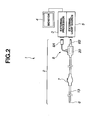
- Fig. 2 is an illustrative diagram illustrating a configuration of the endoscope system 1
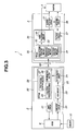
- Fig. 3 is a block diagram illustrating a configuration of the endoscope system 1.
- the endoscope system 1 of the present embodiment includes: an endoscope 2 (hereinafter, also referred to as "scope") having an elongated insertion section 13 which is inserted into a body cavity for picking up an image of a region to be observed with a CCD 6 provided at the distal end portion thereof, and an operation section 7 with which an operator operates the endoscope; a light source apparatus 5 for supplying an illumination light to the endoscope 2; an external processor 3 for processing an image pickup signal from the endoscope 2 and causing a monitor 4 which is display means to display the image or the like from the endoscope; an air/water pump 9 for supplying air and water; and the operation section 7 with which an operator inputs information, and these apparatuses are mounted to a rack 11.
- the endoscope 2 is removably connected to the external processor 3 via a connector section 8A, and to the light source apparatus 5 via a connector section 8B, and also connected to the air/water pump 9 via the connector section 8B.
- the analog image pickup signal is inputted to a pre-processing circuit 20 arranged at the connector section 8 of the endoscope 2 via a transmission cable (not shown) inserted through the insertion section 13, and is processed in the pre-processing circuit 20 to be outputted as a digital image pickup signal to the external processor 3.
- the pre-processing circuit 20 is arranged at the connector section 8, but may be arranged at the operation section 7, or may be divided and arranged at both of the operation section 7 and the connector section 8 for example, as long as the pre-processing circuit 20 is arranged at the endoscope 2.
- the CCD 6 driven by a drive circuit 21 picks up an image of a subject 10 in a body cavity, and outputs an analog image pickup signal of the image to the pre-processing circuit 20.
- the pre-processing circuit 20 includes an amplifier circuit 22, a CDS circuit 23, an AD converter circuit 24, and a first FPGA 29.
- the FPGA is the abbreviation for Field Programmable Gate Array, and is a programmable integrated circuit that can be used as a circuit for a desired operation by programming a desired software.
- the analog image pickup signal passes through the CDS (correlated double sampling) circuit 23 via the amplifier circuit 22 to remove CCD noise included in the signal, and is converted to a digital image pickup signal such as a 12-bit digital image pickup signal in the AD converter circuit 24.
- the digital image pickup signal is transmitted to a second FPGA 35 on the external processor 3 side via the first FPGA 29 and the connector section 8A to be inputted to a post-processing circuit 30.
- the digital image pickup signal is processed in the post-processing circuit 30 to be outputted to the monitor 4 as a video signal, so that the image of the subject 10 by the endoscope is displayed on the monitor 4.
- the endoscope system 1 includes a detection circuit for, in case of a failure, detecting a part of the failure.
- the first FPGA 29 of the endoscope 2 is configured with a test pattern generating section 27 that is provided with a test pattern signal outputting function for generating a test pattern signal of a digital image pickup signal using a program, a JTAG chain creating section 28, and an AFE-detection section 26 which is AFE-detection means.
- the JTAG chain means a circuit that connects input and output ports in series to perform a boundary scan test based on JTAG standard.
- the AFE (Analog Front End) 25 is an element having a circuit for converting analog image data to digital data with peripheral circuits incorporated therein, and outputs a predetermined number of bit of, for example 12-bit, digital pickup image signals.
- the AFE-detection section 26 detects a normal operation of the AFE 25 when there is not a bit drop in the digital image pickup signals outputted from the AFE 25, that is, when the number of bits of the digital image pickup signal is equal to a predetermined number of bits.
- the second FPGA 35 of the external processor 3 is configured with a test pattern generating section 32 that is provided with a test pattern signal outputting function for generating a test pattern signal of a digital image pickup signal, a JTAG chain creating section 34, and a connection-detection section 33.
- the connection-detection section 33 which is connection-detection means forms a consecutive wire circuit with the JTAG chain creating section 28 of the first FPGA 29 and the JTAG chain creating section 34 of the second FPGA 35 via the connector section 8A so as to detect any electrical connection failure at the connector section 8A.
- the external processor 3 further includes a capture circuit 37, instead of the post-processing circuit 30, for capturing an image data from the digital image pickup signal.
- the digital image pickup signal is processed in one of the post-processing circuit 30 and the capture circuit 37 using a switch (not shown) for processing.
- the endoscope system 1 has an output-detection circuit 31 which is output-detection means for detecting the presence or absence of an output signal to the monitor 4.
- the output-detection circuit 31 may be, as shown in Fig. 3 , incorporated in the external processor 3, or may be a separated member.
- the output-detection circuit 31 is able to detect the presence or absence of an output of the image pickup signal from the endoscope 2, that is, a digital image pickup signal, and the presence or absence of an output of the video signal output from the post-processing circuit 30, by detecting the presence or absence of an output signal to the monitor 4, as will be explained later.
- the endoscope system 1 preferably includes a notifying circuit 38 which is means for notifying at least one of the detection results from the output-detection circuit 31, the connection-detection section 33, and the AFE-detection section 26.
- the notifying circuit may be, as shown in Fig. 3 , incorporated in the external processor 3, or may be a separated member.
- the notifying circuit 38 may use the monitor 4 for notifying, and may include a notifying section that uses voice and the like (not shown).
- the endoscope system 1 is an image pickup system including: the endoscope 2 which is an image pickup apparatus for picking up an image of the subject 10 and outputting an image pickup signal of the image; the external processor 3 which is a signal processing apparatus having the post-processing circuit 30 as a signal processing circuit for processing the image pickup signal inputted from the endoscope 2 and generating a video signal that can be outputted to the monitor 4; and the output-detection circuit 31 which is output-detection means for detecting the presence or absence of an output of the image pickup signal and the presence or absence of an output of the video signal.
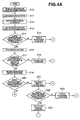
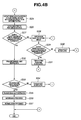
- FIG. 4A and Fig. 4B are flowcharts illustrating the flow of a maintenance process of the endoscope system 1.
- the endoscope system 1 checks in order every part of the system for failure. When a failure is found, the part of the failure is notified.
- the endoscope 2 is connected to the external processor 3. Then, the endoscope system 1 is powered. That is, the endoscope 2, the external processor 3, and the monitor 4 are supplied with power.
- the endoscope system 1 starts a maintenance mode that is an operation mode for performing a series of self-check processes to find any failed part in the endoscope system 1.
- the endoscope system 1 makes a switching to the post-processing circuit 30 between the post-processing circuit 30 and the capture circuit 37. As described above, the switching operation is performed using a switch (not shown) or the like.
- the test pattern generating section 32 of the post-processing circuit 30 outputs a test pattern signal.
- the output-detection circuit 31 detects the presence or absence of an output of the test pattern signal from the post-processing circuit 30. That is, the step S14 is a video signal detection step for detecting the presence or absence of an output of the video signal from the post-processing circuit 30, and also is a test pattern signal detection step for detecting the presence or absence of a test pattern signal.
- the notifying circuit 38 displays a display of "Failure in Post-Processing" on the monitor 4 as a notification.
- step S16 With an outputted test pattern signal (Yes), at step S16, a check is performed on the next part.
- the JTAG chain creating sections 28 and 34 individually create a JTAG chain that connects the input-output lines between the FPGA 29 and the FPGA 35 in series. That is, the ends of a plurality of signal wires in connection via the connector section 8A are connected to each other so that the ends are so-called daisy-chained as one wire functionally.
- the input-output lines of the JTAG chain creating section 34 two lines form the ends of JTAG chain that are connected to the connection-detection section 33.
- connection-detection section 33 is able to detect a connection failure somewhere between the FPGA 29 and the FPGA 35 when the JTAG chain is OPEN, that is, when there is a continuity failure in the JTAG chain.
- the step S 17 is a connection-detection step for detecting the presence or absence of an electrical connection at the connector section 8A.
- the connection-detection section 33 detects a connection failure (Yes)
- the notifying circuit 38 displays a display of "Connection Failure in Scope" on the monitor 4 as a notification.
- the test pattern generating section 27 of the pre-processing circuit 20 outputs a test pattern signal.
- the output-detection circuit 31 detects the presence or absence of an output of the test pattern signal from the pre-processing circuit 20. That is, the step S20 is a digital image pickup signal detection step for detecting an image pickup signal from the endoscope 2, that is, the presence or absence of an output of the digital image pickup signal, and also is a test pattern signal detection step for detecting the presence or absence of a test pattern signal.
- step S21 When the output-detection circuit 31 detects no outputted test pattern signal from the pre-processing circuit 20 (No), the process goes to step S21 because the problem is known to exist in pre-processing circuit 20 or a video processing circuit 36 of the post-processing circuit 30 after the connections in the post-processing circuit 30 and the endoscope 2 are already checked.
- step S25 when the output-detection circuit 31 detects an outputted test pattern signal from the pre-processing circuit 20 (Yes), the process goes to step S25.
- the endoscope system 1 makes a switching to the capture circuit 37 between the post-processing circuit 30 and the capture circuit 37.
- the notifying circuit 38 displays "Failure in Pre-Processing Circuit" on the monitor 4 as a notification.
- the output-detection circuit 31 is able to detect an outputted signal to the monitor 4 through the capture circuit 37 (Yes), it is determined that the video processing circuit 36 has a failed part, and at step S24, the notifying circuit 38 displays "Failure in Video Processing" on the monitor 4 as a notification.
- step S20 when the output-detection circuit 31 detects an outputted test pattern signal from the pre-processing circuit 20 (Yes), a check on the outputting system of the CCD 6 is performed.
- An analog image pickup signal from the CCD 6 is converted to a 12-bit digital image pickup signal by the AFE 25 that includes the CDS circuit 23 and the AD converter circuit 24, to be outputted to the FPGA 29.
- the FPGA 29 outputs the 12-bit digital image pickup signal from the AFE 25 to the post-processing circuit 30.
- a switching is made to the post-processing circuit 30 between the post-processing circuit 30 and the capture circuit 37.
- step S28 when the output-detection circuit 31 is not able to detect any outputted signal from the CCD 6 (No), the process goes to step S28.
- the endoscope system 1 makes a switching to the capture circuit 37 between the post-processing circuit 30 and the capture circuit 37.
- the notifying circuit 38 displays "Failure in CCD" on the monitor 4 as a notification.
- the output-detection circuit 31 is able to detect an outputted signal to the monitor 4 through the capture circuit 37 (Yes), it is determined that the video processing circuit 36 has a failed part, and at step S31, the notifying circuit 38 displays "Failure in Video Processing" on the monitor 4 as a notification.
- the endoscope system 1 finally checks the AFE 25 for failure when there is no problem in the CCD 6, the pre-processing circuit 20, and the post-processing circuit 30.
- the AFE-detection section 26 checks digital signal data for a so-called bit drop. For example, when a digital image pickup signal is supposed to have a predetermined number 12 of bits, the resulting data with a bit drop has 11 bits or less.
- the AFE-detection section 26 determines that the AFE 25 is the failed part, and at step S31, the notifying circuit 38 displays "Failure in AFE" on the monitor 4 as a notification. That is, the step S33 is an AFE-detection step for detecting that the AFE 25 is normally operating when the number of bits of a digital image pickup signal is equal to a predetermined number of bits.
- the operation of the endoscope system 1 is determined to be normal, and the notifying circuit 38 displays "Normally Operating" on the monitor 4 as a notification.
- the endoscope system 1 ends the maintenance mode, and starts a normal operation. To the contrary, with any detection of a failed part in the maintenance mode, that is, in the case (I) of Fig. 4A or Fig. 4B , the endoscope system 1 does not start a normal operation and wait for a response from an operator.
- the endoscope system 1 automatically enters in a maintenance mode at the time of startup, but may go into a maintenance mode in response to an instruction from an operator after the endoscope system 1 starts a normal operation.
- the endoscope system 1 may be set not to automatically enter in a maintenance mode at the time of startup, but go into a maintenance mode in response to an instruction from an operator.
- the maintenance mode is explained as being controlled by the endoscope system 1, but more specifically, the maintenance mode is controlled by a control section (not shown) that controls the endoscope system 1 as a whole.
- the circuits such as the output-detection circuit 31 and the notifying circuit 38 may be included in the control section.
- a failed part is easily determined, and the determination of a failed part is facilitated using the method for maintaining the endoscope system 1 which is a method for maintaining an image pickup system of the present embodiment.
- the endoscope system 1 detects six failed parts therein, including: a failure in post-processing circuit, a connection failure in scope, a failure in pre-processing circuit, a failure in video processing, a failure in CCD, and a failure in AFE, but even in an endoscope system that detects one or more failed parts selected from the six parts, the failed part(s) can be easily determined.
- a method for maintaining an image pickup system of the present embodiment is a method for maintaining the endoscope system 1 which is an image pickup system having the endoscope 2 as an image pickup apparatus for picking up an image of the subject 10 and outputting an image pickup signal of the image, and the external processor 3 which is a signal processing apparatus having the post-processing circuit 30 as a signal processing circuit for processing the image pickup signal inputted from the endoscope 2 via an electrically connectable connector section 8 and outputting a video signal that can be outputted to the monitor 4 as a signal processing circuit, and the method includes: a video signal detection step for detecting the presence or absence of an output of the video signal; a connection-detection step for detecting the presence or absence of an electrical connection at the connector section 8; and an image pickup signal detection step for detecting the presence or absence of an output of the image pickup signal.
- an endoscope system 1B which is an image pickup system of a second embodiment according to the present invention will be explained below.
- the endoscope system 1B of the present embodiment B is similar to the endoscope system 1 of the first embodiment, and the same elements are denoted by the same reference numerals, which will not be explained below.
- Fig. 5 is an external view illustrating the endoscope system 1 B of the present embodiment
- Fig. 6 is a block diagram illustrating a configuration of the endoscope system 1B of the present embodiment.
- the endoscope 2 shown in Fig. 5 is similar to the endoscope 2 of the first embodiment, except that the endoscope 2 is not connected to the external processor 3 and the light source apparatus 5 that are designed for exclusive use with the endoscope 2, but is connected to a PC 41.
- the PC 41 may be a general-purpose personal computer (PC) for example, and includes a CPU (Central Processing Unit) to provide functions such as ones for processing desired data in accordance with software installed therein.
- PC general-purpose personal computer
- CPU Central Processing Unit
- the endoscope 2 is able to output digital image pickup signals by itself. So, the endoscope 2 can be connected to a digital equipment such as a PC, other than the external processor 3 designed for exclusive use with endoscope apparatuses, to be used. In such a use form also, in the endoscope system 1B of the present embodiment, any failed part in the endoscope 2 can be easily determined.
- the connection of the PC 41 to the endoscope 2 enables an appropriate update of the setting installed in the endoscope to response to the cable length.
- a determination of a failed part in the endoscope 2 is easily achieved without using the external processor 3 which is designed for exclusive use with the external processor 3, and also even if the endoscope 2 is not failed, a maintenance of the endoscope 2 such as updating of software therein can be implemented.
- the endoscope system 1B of the present embodiment has the PC 41 and a monitor 42.
- the PC 41 includes: a capture circuit 44 for processing digital image pickup signals; an FPGA writing circuit 45 for writing data into the FPGA of the endoscope 2; and an output-detection circuit 46 which is output-detection means for detecting a failed part in the endoscope 2.
- the endoscope system 1B when the endoscope 2 is connected to the PC 41, a normal display of an image picked up by the endoscope on the monitor 42 indicates that a failed part is included in the external processor, and not included in the endoscope 2. Also, in the endoscope system 1B, a failed part in the endoscope 2 can be determined. That is, the output-detection circuit 46 of the PC 41 is able to detect three failed parts, including: a failure in pre-processing circuit, a failure in CCD, and a failure in AFE. Needless to say, even if the endoscope system 1B is configured to detect one or more failed parts selected from the three parts, the failed part(s) can be easily determined.
- a connection failure in scope can be detected using the JTAG chain creating section 28 of the FPGA 28.
- the endoscope 2 of the present embodiment is able to easily output RAW data of sequential still images to the monitor 4 via the capture circuit 44.
- maintenance operations such as updating of software therein can be implemented via the FPGA writing circuit 45 in the PC 41.
- the PC 41 is provided with a function to switch between a mode for determining a failed part in the endoscope 2 and a normal mode, and the switching operation is performed using a user interface such as a keyboard (not shown) connected to the PC 41.
- the PC 41 When the PC 41 has communication means therein, the PC 41 is able to obtain data such as software contents of the endoscope 2 and software for maintenance through the Internet. Also, the PC 41 enables any updating of the software for the endoscope 2 from a remote service center through the Internet.
- FIG. 7 is an illustrative diagram for illustrating the endoscope system 1C of the present modified example.
- an endoscope 2A has a parallel port terminal 12 at the connector section 8 thereof for a connection with a PC 5.
- the endoscope 2A can be easily connected to a parallel port terminal of the PC 51 such as a printer board.
- the PC 51 is able to obtain data that is necessary for detecting a failed part in the endoscope 2A or updating of software for the endoscope 2A from an external apparatus 52.
- the external apparatus 52 may be a playback apparatus for storage media, or an apparatus that can be connected to a network and obtains necessary data from the network.
- the endoscope 2A is provided with the general-purpose parallel port terminal 12 in addition to the advantages of the endoscope 2, the endoscope 2A can be easily connected to various pieces of general-purpose digital equipment, which facilitates the determining of a part to repair, and also the output of RAW data of sequential still images to the monitor 42.
- FIG. 8 is a conceptual diagram illustrating a use form of the endoscope system 1D of the present embodiment
- Fig. 9 is a block diagram illustrating a configuration of the endoscope system 1D of the present embodiment.
- the endoscope 2B of the present embodiment is a so-called capsule endoscope.
- the capsule endoscope 2B is configured so that, after swallowed by a subject 10B who is an object of observation or examination, the capsule endoscope 2B moves through the organs such as stomach and small intestine by peristaltic movement until the spontaneous elimination so that the capsule endoscope 2B picks up images of the inside of the organs in series with the function for image pickup.
- the images picked up by the capsule endoscope 2B are transmitted to an external processor 3B via radio communication and through a receiving coil 15 that is disposed outside of the body of the subject 10B, to be displayed on the monitor 4.
- the CCD 6 of the endoscope 2B picks up images in the subject 10B while moving through the organs, and the analog image pickup signals of the images are converted to digital image pickup signals by the pre-processing circuit 20 of the endoscope 2B, and transmitted to the outside of the body through radio transmitting means.
- the digital image pickup signals transmitted to the outside of the body are inputted to the external processor 3B through radio receiving means, and processed by the post-processing circuit 30 to be displayed on the monitor 4.
- the endoscope system 1D has configurations, operations, and effects similar to those of the endoscope system 1 of the first embodiment, except the difference in the means for transmitting image pickup signals from the endoscope 2B to the external processor 3 between wire and wireless.
- the endoscope system 1D is able to detect five failed parts, including: a failure in post-processing circuit, pre-processing circuit, a failure in video processing, a failure in CCD, and a failure in AFE.
- the connection-detection section 33 detects a failure of the receiving coil 15 such as disconnection, which results in a detection of a connection failure.
- the endoscope system 1D is an image pickup system in which a failed part can be easily determined.
- FIG. 10 is a block diagram illustrating a configuration of the endoscope system 1E of the present embodiment.
- the endoscope 2 of the endoscope system 1E is similar to the endoscope 2 of the first embodiment.
- the external processor 3C is different from the external processor 3 of the first embodiment in that external processor 3C does not include any output-detection circuit.
- the external processor 3C of the endoscope system 1E has a communication circuit 63 as communication means, so as to be connectable through a communications line to a communication circuit 62 of a detection apparatus 60 which is installed at another place.
- the detection apparatus 60 includes an output-detection circuit 61 and the like which are used to determine a failed part in the endoscope system 1E and perform maintenances such as updating of software.
- the detection apparatus 60 may be a PC.
- the communications line may be a known communications line such as the Internet connection and cell phone connection.
- the endoscope system 1E provides the same advantages as those of the endoscope system 1 of the first embodiment, and also enables an easy determination of a failed part therein from a remote place.
- an endoscope was used as an image pickup apparatus, and an external processor or a PC were used as a signal processing apparatus, the present invention is not limited to an endoscope as long as the image pickup apparatus picks up an image of a subject and outputs an image pickup signal of the image, and is not limited to an endoscope external processor or a PC as long as the signal processing apparatus has a signal processing circuit that processes an image pickup signal inputted from an image pickup apparatus and is able to output a video signal to a monitor or the like.
- an image pickup system and a method for maintaining the image pickup system of the present invention are not limited to an endoscope system and a method for maintaining the endoscope system.
Landscapes
- Engineering & Computer Science (AREA)
- Health & Medical Sciences (AREA)
- Life Sciences & Earth Sciences (AREA)
- Physics & Mathematics (AREA)
- Signal Processing (AREA)
- Multimedia (AREA)
- General Health & Medical Sciences (AREA)
- General Physics & Mathematics (AREA)
- General Engineering & Computer Science (AREA)
- Surgery (AREA)
- Biomedical Technology (AREA)
- Pathology (AREA)
- Radiology & Medical Imaging (AREA)
- Molecular Biology (AREA)
- Animal Behavior & Ethology (AREA)
- Heart & Thoracic Surgery (AREA)
- Public Health (AREA)
- Veterinary Medicine (AREA)
- Medical Informatics (AREA)
- Optics & Photonics (AREA)
- Nuclear Medicine, Radiotherapy & Molecular Imaging (AREA)
- Biophysics (AREA)
- Endoscopes (AREA)
- Instruments For Viewing The Inside Of Hollow Bodies (AREA)
- Measurement Of The Respiration, Hearing Ability, Form, And Blood Characteristics Of Living Organisms (AREA)
- Closed-Circuit Television Systems (AREA)
Abstract
Description
- The present invention relates to an image pickup system that includes an image pickup apparatus for picking up an image of a subject and outputting an image pickup signal of the image and a signal processing apparatus having a signal processing circuit for processing the image pickup signal inputted from the image pickup apparatus, and a method for maintaining the image pickup system.
- In the medical and other fields, so-called electronic endoscope apparatuses have been widely used, each of the apparatuses being provided with a charge coupled device (CCD) as a solid-state image sensing device at a distal end portion of an insertion section of the endoscope, and the CCD is used to pick up an image of a subject and the image from the endoscope is displayed on a monitor. Generally, the electronic endoscope apparatus is configured so that an analog image pickup signal from an electronic endoscope that has a CCD therein is transmitted to an external processor connected to the electronic endoscope so as to be exposed to various processes. That is, an image pickup apparatus for picking up an image of a subject and outputting an image pickup signal of the image outputs an analog image pickup signal, which is digitalized for processes in a signal processing apparatus.
- To the contrary, a so-called electronic endoscope is known, in which for downsizing of a signal processing circuit, a part of the signal processing circuit is mounted to the endoscope, and an analog image pickup signal from a CCD is converted to a digital image pickup signal before the signal is outputted to an external processor which is a signal processing apparatus.
- For example, Japanese Patent Application Laid-Open Publication No.
2006-288753 - An image pickup system of the present invention includes: an image pickup apparatus for picking up an image of a subject and outputting an image pickup signal of the image; a signal processing apparatus having a signal processing circuit which processes the image pickup signal inputted from the image pickup apparatus and generates a video signal that can be outputted to display means; and output-detection means for detecting the presence or absence of an output of the image pickup signal and the presence or absence of an output of the video signal.
- A method for maintaining an image pickup system of the present invention is a method for maintaining an image pickup system having an image pickup apparatus for picking up an image of a subject and outputting an image pickup signal of the image, and a signal processing apparatus having a signal processing circuit which processes the image pickup signal via an electrically connectable connector section from the image pickup apparatus and generates a video signal that can be outputted to display means, including: a video signal detection step for detecting the presence or absence of an output of the video signal; a connection detection step for detecting the presence or absence of an electrical connection at the connector section; and an image pickup signal detection step for detecting the presence or absence of an output of the image pickup signal.
-
-
Fig. 1 is an external view showing a configuration of an endoscope system of a first embodiment; -
Fig. 2 is an illustrative diagram illustrating a configuration of the endoscope system of the first embodiment; -
Fig. 3 is a block diagram illustrating a configuration of the endoscope system of the first embodiment; -
Fig. 4A is a flowchart illustrating a check flow of the endoscope system of the first embodiment; -
Fig. 4B is a flowchart illustrating a check flow of the endoscope system of the first embodiment; -
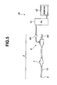
Fig. 5 is an illustrative diagram illustrating a configuration of an endoscope system of a second embodiment; -
Fig. 6 is a block diagram illustrating a configuration of the endoscope system of the second embodiment; -
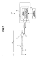
Fig. 7 is an illustrative diagram illustrating a configuration of an endoscope system of a modified example of the second embodiment; -
Fig. 8 is a conceptual diagram illustrating a use form of an endoscope system of a third embodiment; -
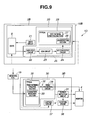
Fig. 9 is a block diagram illustrating a configuration of the endoscope system of the third embodiment; and -
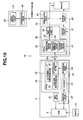
Fig. 10 is a block diagram illustrating a configuration of an endoscope system of a fourth embodiment. - Now, with reference to
Figs. 1 to 3 , anendoscope system 1 of a first embodiment according to the present invention will be explained below.Fig. 1 is an external view showing a configuration of theendoscope system 1 of the present embodiment;Fig. 2 is an illustrative diagram illustrating a configuration of theendoscope system 1; andFig. 3 is a block diagram illustrating a configuration of theendoscope system 1. - As shown in
Fig. 1 , theendoscope system 1 of the present embodiment includes: an endoscope 2 (hereinafter, also referred to as "scope") having anelongated insertion section 13 which is inserted into a body cavity for picking up an image of a region to be observed with aCCD 6 provided at the distal end portion thereof, and anoperation section 7 with which an operator operates the endoscope; alight source apparatus 5 for supplying an illumination light to theendoscope 2; anexternal processor 3 for processing an image pickup signal from theendoscope 2 and causing amonitor 4 which is display means to display the image or the like from the endoscope; an air/water pump 9 for supplying air and water; and theoperation section 7 with which an operator inputs information, and these apparatuses are mounted to arack 11. Theendoscope 2 is removably connected to theexternal processor 3 via aconnector section 8A, and to thelight source apparatus 5 via aconnector section 8B, and also connected to the air/water pump 9 via theconnector section 8B. - As shown in
Fig. 2 , when theCCD 6 arranged at the distal end portion of theinsertion section 13 outputs an analog image pickup signal, the analog image pickup signal is inputted to apre-processing circuit 20 arranged at theconnector section 8 of theendoscope 2 via a transmission cable (not shown) inserted through theinsertion section 13, and is processed in thepre-processing circuit 20 to be outputted as a digital image pickup signal to theexternal processor 3. InFig. 2 , thepre-processing circuit 20 is arranged at theconnector section 8, but may be arranged at theoperation section 7, or may be divided and arranged at both of theoperation section 7 and theconnector section 8 for example, as long as thepre-processing circuit 20 is arranged at theendoscope 2. - Next, with reference to
Fig. 3 , a configuration of theendoscope system 1 of the present embodiment will be explained below in more detail. In theendoscope system 1, theCCD 6 driven by adrive circuit 21 picks up an image of asubject 10 in a body cavity, and outputs an analog image pickup signal of the image to thepre-processing circuit 20. Thepre-processing circuit 20 includes anamplifier circuit 22, aCDS circuit 23, anAD converter circuit 24, and afirst FPGA 29. The FPGA is the abbreviation for Field Programmable Gate Array, and is a programmable integrated circuit that can be used as a circuit for a desired operation by programming a desired software. - The analog image pickup signal passes through the CDS (correlated double sampling)
circuit 23 via theamplifier circuit 22 to remove CCD noise included in the signal, and is converted to a digital image pickup signal such as a 12-bit digital image pickup signal in theAD converter circuit 24. The digital image pickup signal is transmitted to asecond FPGA 35 on theexternal processor 3 side via thefirst FPGA 29 and theconnector section 8A to be inputted to apost-processing circuit 30. The digital image pickup signal is processed in thepost-processing circuit 30 to be outputted to themonitor 4 as a video signal, so that the image of thesubject 10 by the endoscope is displayed on themonitor 4. - As shown in
Fig. 3 , theendoscope system 1 includes a detection circuit for, in case of a failure, detecting a part of the failure. Thefirst FPGA 29 of theendoscope 2 is configured with a testpattern generating section 27 that is provided with a test pattern signal outputting function for generating a test pattern signal of a digital image pickup signal using a program, a JTAGchain creating section 28, and an AFE-detection section 26 which is AFE-detection means. The JTAG chain means a circuit that connects input and output ports in series to perform a boundary scan test based on JTAG standard. The AFE (Analog Front End) 25 is an element having a circuit for converting analog image data to digital data with peripheral circuits incorporated therein, and outputs a predetermined number of bit of, for example 12-bit, digital pickup image signals. The AFE-detection section 26 detects a normal operation of theAFE 25 when there is not a bit drop in the digital image pickup signals outputted from the AFE 25, that is, when the number of bits of the digital image pickup signal is equal to a predetermined number of bits. - The
second FPGA 35 of theexternal processor 3 is configured with a testpattern generating section 32 that is provided with a test pattern signal outputting function for generating a test pattern signal of a digital image pickup signal, a JTAGchain creating section 34, and a connection-detection section 33. The connection-detection section 33 which is connection-detection means forms a consecutive wire circuit with the JTAGchain creating section 28 of thefirst FPGA 29 and the JTAGchain creating section 34 of thesecond FPGA 35 via theconnector section 8A so as to detect any electrical connection failure at theconnector section 8A. Theexternal processor 3 further includes acapture circuit 37, instead of thepost-processing circuit 30, for capturing an image data from the digital image pickup signal. The digital image pickup signal is processed in one of thepost-processing circuit 30 and thecapture circuit 37 using a switch (not shown) for processing. - The
endoscope system 1 has an output-detection circuit 31 which is output-detection means for detecting the presence or absence of an output signal to themonitor 4. The output-detection circuit 31 may be, as shown inFig. 3 , incorporated in theexternal processor 3, or may be a separated member. The output-detection circuit 31 is able to detect the presence or absence of an output of the image pickup signal from theendoscope 2, that is, a digital image pickup signal, and the presence or absence of an output of the video signal output from thepost-processing circuit 30, by detecting the presence or absence of an output signal to themonitor 4, as will be explained later. - Furthermore, the
endoscope system 1 preferably includes a notifyingcircuit 38 which is means for notifying at least one of the detection results from the output-detection circuit 31, the connection-detection section 33, and the AFE-detection section 26. The notifying circuit may be, as shown inFig. 3 , incorporated in theexternal processor 3, or may be a separated member. The notifyingcircuit 38 may use themonitor 4 for notifying, and may include a notifying section that uses voice and the like (not shown). - As described above, the
endoscope system 1 is an image pickup system including: theendoscope 2 which is an image pickup apparatus for picking up an image of thesubject 10 and outputting an image pickup signal of the image; theexternal processor 3 which is a signal processing apparatus having thepost-processing circuit 30 as a signal processing circuit for processing the image pickup signal inputted from theendoscope 2 and generating a video signal that can be outputted to themonitor 4; and the output-detection circuit 31 which is output-detection means for detecting the presence or absence of an output of the image pickup signal and the presence or absence of an output of the video signal. - Next, with reference to
Fig. 4A andFig. 4B , the flow of a maintenance process of theendoscope system 1 will be explained below.Fig. 4A andFig. 4B are flowcharts illustrating the flow of a maintenance process of theendoscope system 1. - As shown in
Fig. 4A andFig. 4B , theendoscope system 1 checks in order every part of the system for failure. When a failure is found, the part of the failure is notified. - The
endoscope 2 is connected to theexternal processor 3. Then, theendoscope system 1 is powered. That is, theendoscope 2, theexternal processor 3, and themonitor 4 are supplied with power. - The
endoscope system 1 starts a maintenance mode that is an operation mode for performing a series of self-check processes to find any failed part in theendoscope system 1. - The
endoscope system 1 makes a switching to thepost-processing circuit 30 between thepost-processing circuit 30 and thecapture circuit 37. As described above, the switching operation is performed using a switch (not shown) or the like. - The test
pattern generating section 32 of thepost-processing circuit 30 outputs a test pattern signal. - The output-
detection circuit 31 detects the presence or absence of an output of the test pattern signal from thepost-processing circuit 30. That is, the step S14 is a video signal detection step for detecting the presence or absence of an output of the video signal from thepost-processing circuit 30, and also is a test pattern signal detection step for detecting the presence or absence of a test pattern signal. - Without any outputted test pattern signal (No), at
step S 15, the notifyingcircuit 38 displays a display of "Failure in Post-Processing" on themonitor 4 as a notification. - With an outputted test pattern signal (Yes), at step S16, a check is performed on the next part.
- The JTAG
chain creating sections FPGA 29 and theFPGA 35 in series. That is, the ends of a plurality of signal wires in connection via theconnector section 8A are connected to each other so that the ends are so-called daisy-chained as one wire functionally. Among the input-output lines of the JTAGchain creating section 34, two lines form the ends of JTAG chain that are connected to the connection-detection section 33. - The connection-
detection section 33 is able to detect a connection failure somewhere between theFPGA 29 and theFPGA 35 when the JTAG chain is OPEN, that is, when there is a continuity failure in the JTAG chain. In other words, the step S 17 is a connection-detection step for detecting the presence or absence of an electrical connection at theconnector section 8A. When the connection-detection section 33 detects a connection failure (Yes), at step S18, the notifyingcircuit 38 displays a display of "Connection Failure in Scope" on themonitor 4 as a notification. - When the JTAG chain is CLOSE (No), at step S 19, a check is performed on the next part.
- The test
pattern generating section 27 of thepre-processing circuit 20 outputs a test pattern signal. - The output-
detection circuit 31 detects the presence or absence of an output of the test pattern signal from thepre-processing circuit 20. That is, the step S20 is a digital image pickup signal detection step for detecting an image pickup signal from theendoscope 2, that is, the presence or absence of an output of the digital image pickup signal, and also is a test pattern signal detection step for detecting the presence or absence of a test pattern signal. - When the output-
detection circuit 31 detects no outputted test pattern signal from the pre-processing circuit 20 (No), the process goes to step S21 because the problem is known to exist inpre-processing circuit 20 or avideo processing circuit 36 of thepost-processing circuit 30 after the connections in thepost-processing circuit 30 and theendoscope 2 are already checked. - To the contrary, when the output-
detection circuit 31 detects an outputted test pattern signal from the pre-processing circuit 20 (Yes), the process goes to step S25. - The
endoscope system 1 makes a switching to thecapture circuit 37 between thepost-processing circuit 30 and thecapture circuit 37. - When the output-
detection circuit 31 cannot detect any outputted signal to themonitor 4 even through the capture circuit 37 (No), it is determined that thepre-processing circuit 20 has a failed part, and at step S23, the notifyingcircuit 38 displays "Failure in Pre-Processing Circuit" on themonitor 4 as a notification. - To the contrary, when the output-
detection circuit 31 is able to detect an outputted signal to themonitor 4 through the capture circuit 37 (Yes), it is determined that thevideo processing circuit 36 has a failed part, and at step S24, the notifyingcircuit 38 displays "Failure in Video Processing" on themonitor 4 as a notification. - At step S20, when the output-
detection circuit 31 detects an outputted test pattern signal from the pre-processing circuit 20 (Yes), a check on the outputting system of theCCD 6 is performed. An analog image pickup signal from theCCD 6 is converted to a 12-bit digital image pickup signal by theAFE 25 that includes theCDS circuit 23 and theAD converter circuit 24, to be outputted to theFPGA 29. - The
FPGA 29 outputs the 12-bit digital image pickup signal from theAFE 25 to thepost-processing circuit 30. Here, a switching is made to thepost-processing circuit 30 between thepost-processing circuit 30 and thecapture circuit 37. - When the output-
detection circuit 31 is able to detect an outputted signal from the CCD 6 (Yes), it is determined that theCCD 6 does not have any failed part, and the process goes to step S32. - To the contrary, when the output-
detection circuit 31 is not able to detect any outputted signal from the CCD 6 (No), the process goes to step S28. - The
endoscope system 1 makes a switching to thecapture circuit 37 between thepost-processing circuit 30 and thecapture circuit 37. - When the output-
detection circuit 31 is not able to detect any outputted signal to themonitor 4 even through the capture circuit 37 (No), it is determined that theCCD 6 has a failed part, and at step S30, the notifyingcircuit 38 displays "Failure in CCD" on themonitor 4 as a notification. - To the contrary, when the output-
detection circuit 31 is able to detect an outputted signal to themonitor 4 through the capture circuit 37 (Yes), it is determined that thevideo processing circuit 36 has a failed part, and at step S31, the notifyingcircuit 38 displays "Failure in Video Processing" on themonitor 4 as a notification. - The
endoscope system 1 finally checks theAFE 25 for failure when there is no problem in theCCD 6, thepre-processing circuit 20, and thepost-processing circuit 30. - In the final check, the AFE-
detection section 26 checks digital signal data for a so-called bit drop. For example, when a digital image pickup signal is supposed to have a predeterminednumber 12 of bits, the resulting data with a bit drop has 11 bits or less. - When finding a bit drop (No), the AFE-
detection section 26 determines that theAFE 25 is the failed part, and at step S31, the notifyingcircuit 38 displays "Failure in AFE" on themonitor 4 as a notification. That is, the step S33 is an AFE-detection step for detecting that theAFE 25 is normally operating when the number of bits of a digital image pickup signal is equal to a predetermined number of bits. - Without any detection of failed part in the above described entire processings, the operation of the
endoscope system 1 is determined to be normal, and the notifyingcircuit 38 displays "Normally Operating" on themonitor 4 as a notification. - The
endoscope system 1 ends the maintenance mode, and starts a normal operation. To the contrary, with any detection of a failed part in the maintenance mode, that is, in the case (I) ofFig. 4A orFig. 4B , theendoscope system 1 does not start a normal operation and wait for a response from an operator. - In the above description, the
endoscope system 1 automatically enters in a maintenance mode at the time of startup, but may go into a maintenance mode in response to an instruction from an operator after theendoscope system 1 starts a normal operation. Alternatively, theendoscope system 1 may be set not to automatically enter in a maintenance mode at the time of startup, but go into a maintenance mode in response to an instruction from an operator. - Also, in the above description, the maintenance mode is explained as being controlled by the
endoscope system 1, but more specifically, the maintenance mode is controlled by a control section (not shown) that controls theendoscope system 1 as a whole. The circuits such as the output-detection circuit 31 and the notifyingcircuit 38 may be included in the control section. - As described above, in the
endoscope system 1 which is an image pickup system of the present embodiment, a failed part is easily determined, and the determination of a failed part is facilitated using the method for maintaining theendoscope system 1 which is a method for maintaining an image pickup system of the present embodiment. - In addition, in the above description, the
endoscope system 1 detects six failed parts therein, including: a failure in post-processing circuit, a connection failure in scope, a failure in pre-processing circuit, a failure in video processing, a failure in CCD, and a failure in AFE, but even in an endoscope system that detects one or more failed parts selected from the six parts, the failed part(s) can be easily determined. - As described above, a method for maintaining an image pickup system of the present embodiment is a method for maintaining the
endoscope system 1 which is an image pickup system having theendoscope 2 as an image pickup apparatus for picking up an image of the subject 10 and outputting an image pickup signal of the image, and theexternal processor 3 which is a signal processing apparatus having thepost-processing circuit 30 as a signal processing circuit for processing the image pickup signal inputted from theendoscope 2 via an electricallyconnectable connector section 8 and outputting a video signal that can be outputted to themonitor 4 as a signal processing circuit, and the method includes: a video signal detection step for detecting the presence or absence of an output of the video signal; a connection-detection step for detecting the presence or absence of an electrical connection at theconnector section 8; and an image pickup signal detection step for detecting the presence or absence of an output of the image pickup signal. - Now, with reference to
Fig. 5 andFig. 6 , anendoscope system 1B which is an image pickup system of a second embodiment according to the present invention will be explained below. Theendoscope system 1B of the present embodiment B is similar to theendoscope system 1 of the first embodiment, and the same elements are denoted by the same reference numerals, which will not be explained below. -
Fig. 5 is an external view illustrating theendoscope system 1 B of the present embodiment, andFig. 6 is a block diagram illustrating a configuration of theendoscope system 1B of the present embodiment. - The
endoscope 2 shown inFig. 5 is similar to theendoscope 2 of the first embodiment, except that theendoscope 2 is not connected to theexternal processor 3 and thelight source apparatus 5 that are designed for exclusive use with theendoscope 2, but is connected to aPC 41. ThePC 41 may be a general-purpose personal computer (PC) for example, and includes a CPU (Central Processing Unit) to provide functions such as ones for processing desired data in accordance with software installed therein. - The
endoscope 2 is able to output digital image pickup signals by itself. So, theendoscope 2 can be connected to a digital equipment such as a PC, other than theexternal processor 3 designed for exclusive use with endoscope apparatuses, to be used. In such a use form also, in theendoscope system 1B of the present embodiment, any failed part in theendoscope 2 can be easily determined. - That is, during a treatment using an endoscope, even if an abnormal vision is observed in an image picked up by the endoscope, sometimes the treatment should be continued using the endoscope. In the case, an operator uses a spare endoscope, that is, the failed endoscope is removed from the
external processor 3, and the spare endoscope is connected to theexternal processor 3, which makes it impossible to determine a failed part of the failed endoscope using theexternal processor 3. - However, in the case of the
endoscope system 1B of the second embodiment of the present invention, as shown inFig. 5 , an operator can connect theendoscope 2 to thePC 41 via theconnector section 8A, which makes the determination of a failed part possible. When thePC 41 cannot be directly connected to theconnector section 8A, a converter may be interposed between thePC 41 and theconnector section 8A for connection. - In addition, when the software for internal processing circuits of the
endoscope 2 such as theFPGA 29 is updated, or when the transmission cable has a shorter length due to repairing of a breakage of the cable, the connection of thePC 41 to theendoscope 2 enables an appropriate update of the setting installed in the endoscope to response to the cable length. - That is, in the
endoscope system 1B of the present embodiment, a determination of a failed part in theendoscope 2 is easily achieved without using theexternal processor 3 which is designed for exclusive use with theexternal processor 3, and also even if theendoscope 2 is not failed, a maintenance of theendoscope 2 such as updating of software therein can be implemented. - Furthermore, as shown in
Fig. 6 , theendoscope system 1B of the present embodiment has thePC 41 and amonitor 42. ThePC 41 includes: acapture circuit 44 for processing digital image pickup signals; anFPGA writing circuit 45 for writing data into the FPGA of theendoscope 2; and an output-detection circuit 46 which is output-detection means for detecting a failed part in theendoscope 2. - In the
endoscope system 1B, when theendoscope 2 is connected to thePC 41, a normal display of an image picked up by the endoscope on themonitor 42 indicates that a failed part is included in the external processor, and not included in theendoscope 2. Also, in theendoscope system 1B, a failed part in theendoscope 2 can be determined. That is, the output-detection circuit 46 of thePC 41 is able to detect three failed parts, including: a failure in pre-processing circuit, a failure in CCD, and a failure in AFE. Needless to say, even if theendoscope system 1B is configured to detect one or more failed parts selected from the three parts, the failed part(s) can be easily determined. - In the
endoscope system 1B also, a connection failure in scope can be detected using the JTAGchain creating section 28 of theFPGA 28. - The
endoscope 2 of the present embodiment is able to easily output RAW data of sequential still images to themonitor 4 via thecapture circuit 44. - Furthermore, in the
endoscope 2 of the present embodiment, maintenance operations such as updating of software therein can be implemented via theFPGA writing circuit 45 in thePC 41. - That is, the
PC 41 is provided with a function to switch between a mode for determining a failed part in theendoscope 2 and a normal mode, and the switching operation is performed using a user interface such as a keyboard (not shown) connected to thePC 41. - When the
PC 41 has communication means therein, thePC 41 is able to obtain data such as software contents of theendoscope 2 and software for maintenance through the Internet. Also, thePC 41 enables any updating of the software for theendoscope 2 from a remote service center through the Internet. - Now, with reference to
Fig. 7 , anendoscope system 1C which is an image pickup system of a modified example of the second embodiment according to the present invention will be explained below. Theendoscope system 1C of the present modified example is similar to theendoscope system 1 of the first embodiment, and the same elements are denoted by the same reference numerals, which will not be explained below.Fig. 7 is an illustrative diagram for illustrating theendoscope system 1C of the present modified example. - In the
endoscope system 1C shown inFig. 7 , anendoscope 2A has aparallel port terminal 12 at theconnector section 8 thereof for a connection with aPC 5. Thus, theendoscope 2A can be easily connected to a parallel port terminal of thePC 51 such as a printer board. ThePC 51 is able to obtain data that is necessary for detecting a failed part in theendoscope 2A or updating of software for theendoscope 2A from anexternal apparatus 52. Theexternal apparatus 52 may be a playback apparatus for storage media, or an apparatus that can be connected to a network and obtains necessary data from the network. - Because the
endoscope 2A is provided with the general-purposeparallel port terminal 12 in addition to the advantages of theendoscope 2, theendoscope 2A can be easily connected to various pieces of general-purpose digital equipment, which facilitates the determining of a part to repair, and also the output of RAW data of sequential still images to themonitor 42. - Now, with reference to
Fig. 8 andFig. 9 , anendoscope system 1D of a third embodiment according to the present invention will be explained below. Theendoscope system 1D of the present embodiment is similar to theendoscope system 1 of the first embodiment, and the same elements are denoted by the same reference numerals, which will not be explained below.Fig. 8 is a conceptual diagram illustrating a use form of theendoscope system 1D of the present embodiment, andFig. 9 is a block diagram illustrating a configuration of theendoscope system 1D of the present embodiment. - As shown in
Fig. 8 , theendoscope 2B of the present embodiment is a so-called capsule endoscope. Thecapsule endoscope 2B is configured so that, after swallowed by a subject 10B who is an object of observation or examination, thecapsule endoscope 2B moves through the organs such as stomach and small intestine by peristaltic movement until the spontaneous elimination so that thecapsule endoscope 2B picks up images of the inside of the organs in series with the function for image pickup. - The images picked up by the
capsule endoscope 2B are transmitted to anexternal processor 3B via radio communication and through a receivingcoil 15 that is disposed outside of the body of the subject 10B, to be displayed on themonitor 4. - That is, as shown in
Fig. 9 , theCCD 6 of theendoscope 2B picks up images in the subject 10B while moving through the organs, and the analog image pickup signals of the images are converted to digital image pickup signals by thepre-processing circuit 20 of theendoscope 2B, and transmitted to the outside of the body through radio transmitting means. The digital image pickup signals transmitted to the outside of the body are inputted to theexternal processor 3B through radio receiving means, and processed by thepost-processing circuit 30 to be displayed on themonitor 4. - As compared to the
endoscope system 1 of the first embodiment, theendoscope system 1D has configurations, operations, and effects similar to those of theendoscope system 1 of the first embodiment, except the difference in the means for transmitting image pickup signals from theendoscope 2B to theexternal processor 3 between wire and wireless. - That is, the
endoscope system 1D is able to detect five failed parts, including: a failure in post-processing circuit, pre-processing circuit, a failure in video processing, a failure in CCD, and a failure in AFE. In theendoscope system 1D, the connection-detection section 33 detects a failure of the receivingcoil 15 such as disconnection, which results in a detection of a connection failure. - As described above, the
endoscope system 1D is an image pickup system in which a failed part can be easily determined. - Now, with reference to
Fig. 10 , anendoscope system 1E of a fourth embodiment according to the present invention will be explained below. Theendoscope system 1E of the present embodiment is similar to theendoscope system 1 of the first embodiment, and the same elements are denoted by the same reference numerals, which will not be explained below.Fig. 10 is a block diagram illustrating a configuration of theendoscope system 1E of the present embodiment. - The
endoscope 2 of theendoscope system 1E is similar to theendoscope 2 of the first embodiment. However, the external processor 3C is different from theexternal processor 3 of the first embodiment in that external processor 3C does not include any output-detection circuit. Instead, the external processor 3C of theendoscope system 1E has acommunication circuit 63 as communication means, so as to be connectable through a communications line to acommunication circuit 62 of adetection apparatus 60 which is installed at another place. Thedetection apparatus 60 includes an output-detection circuit 61 and the like which are used to determine a failed part in theendoscope system 1E and perform maintenances such as updating of software. Thedetection apparatus 60 may be a PC. - That is, when the
endoscope system 1 E is connected to a communications line, a determination of a failed part in theendoscope system 1E or maintenance for every updating of software in theendoscope system 1 E can be implemented from a remote place. - The communications line may be a known communications line such as the Internet connection and cell phone connection.
- The
endoscope system 1E provides the same advantages as those of theendoscope system 1 of the first embodiment, and also enables an easy determination of a failed part therein from a remote place. - In the above description, an endoscope was used as an image pickup apparatus, and an external processor or a PC were used as a signal processing apparatus, the present invention is not limited to an endoscope as long as the image pickup apparatus picks up an image of a subject and outputs an image pickup signal of the image, and is not limited to an endoscope external processor or a PC as long as the signal processing apparatus has a signal processing circuit that processes an image pickup signal inputted from an image pickup apparatus and is able to output a video signal to a monitor or the like. Similarly, an image pickup system and a method for maintaining the image pickup system of the present invention are not limited to an endoscope system and a method for maintaining the endoscope system.
Claims (15)
- An image pickup system, comprising:an image pickup apparatus for picking up an image of a subject and outputting an image pickup signal of the image;a signal processing apparatus having a signal processing circuit which processes the image pickup signal inputted from the image pickup apparatus and generates a video signal that can be outputted to display means; andoutput-detection means for detecting the presence or absence of an output of the image pickup signal and the presence or absence of an output of the video signal.
- The image pickup system according to claim 1, further comprising
a connector section which is able to electrically connect the image pickup apparatus and the signal processing apparatus to each other; and
connection-detection means for detecting the presence or absence of an electrical connection at the connector section. - The image pickup system according to claim 2, wherein
the image pickup apparatus and the signal processing apparatus include first and second FPGAs that are able to generate a JTAG chain, respectively, and
the connection-detection means detects the presence or absence of an electrical connection at the connector section using the JTAG chains created by the first and second FPGAs. - The image pickup system according to any one of claims 1 to 3, further comprising:an image pickup device for picking up an image of the subject and outputting an analog image pickup signal of the image;an analog front end that processes the analog image pickup signal and outputs a predetermined number of bits of a digital image pickup signal; andAFE-detection means for detecting if the analog front end is normally operating or not.
- The image pickup system according to claim 4, wherein
the AFE-detection means detects a normal operation of the analog front end when the number of bits of the digital image pickup signal is equal to the predetermined number of bits. - The image pickup system according to any one of claims 1 to 5, wherein
the image pickup apparatus and the signal processing apparatus include first and second FPGAs that have a function to output a test pattern signal, respectively, and
the output-detection means detects the presence or absence of at least one of the test pattern signals. - The image pickup system according to any one of claims 4 to 6, further comprising:notifying means for notifying at least one of the detection results from the output-detection means, the connection-detection means, and the AFE-detection means.
- The image pickup system according to any one of claims 1 to 7, wherein
the image pickup apparatus is an endoscope, the signal processing apparatus is an endoscope signal processing apparatus. - The image pickup system according to any one of claims 4 to 8, wherein
the signal processing apparatus includes communication means, and
at least one of the output-detection means, the connection-detection means, and AFE-detection means is able to be controlled via the communication means. - The image pickup system according to any one of claims 1 to 9, wherein
the image pickup apparatus is an endoscope, and the signal processing apparatus is a PC. - A method for maintaining an image pickup system that includes an image pickup apparatus and a signal processing apparatus, comprising:a video signal detection step for detecting the presence or absence of an output of a video signal from a signal processing apparatus having a signal processing circuit that processes the video signal inputted from the image pickup apparatus for picking up an image of a subject and outputting an image pickup signal of the image via an electrically connectable connector section and outputs the video signal that can be outputted to display means;a connection-detection step for detecting the presence or absence of an electrical connection at the connector section; andan image pickup signal detection step for detecting the presence or absence of an output of the image pickup signal.
- The method for maintaining an image pickup system according to claim 11, wherein
the image pickup apparatus further comprising:an image pickup device for picking up an image of a subject and outputting an analog image pickup signal of the image; and an analog front end for processing the analog image pickup signal and outputting a predetermined number of bits of a digital image pickup signal, andthe method further comprising:an AFE-detection step for detecting a normal operation of the analog front end when the number of bits of the digital image pickup signal is equal to the predetermined number of bits. - The method for maintaining an image pickup system according to claim 11 or 12, wherein
the image pickup apparatus and the signal processing apparatus include first and second FPGAs that have a function to output a test pattern signal, respectively, and
the method further comprising:a test pattern signal detection step for detecting the presence or absence of each of the test pattern signals. - The method for maintaining an image pickup system according to any one of claims 11 to 13, further comprising:a notifying step for notifying at least one of the detection results in the video signal detection step, the connection-detection step, the digital image pickup signal detection step, the AFE-detection step, and the test pattern signal detection step.
- The method for maintaining an image pickup system according to any one of claims 11 to 13, wherein
the image pickup apparatus is an endoscope, and the signal processing apparatus is an endoscope signal processing apparatus.
Applications Claiming Priority (1)
| Application Number | Priority Date | Filing Date | Title |
|---|---|---|---|
| JP2008078829A JP5464815B2 (en) | 2008-03-25 | 2008-03-25 | Imaging system and operation method of self-check processing of imaging system |
Publications (3)
| Publication Number | Publication Date |
|---|---|
| EP2106124A2 true EP2106124A2 (en) | 2009-09-30 |
| EP2106124A3 EP2106124A3 (en) | 2011-06-08 |
| EP2106124B1 EP2106124B1 (en) | 2016-05-04 |
Family
ID=40723128
Family Applications (1)
| Application Number | Title | Priority Date | Filing Date |
|---|---|---|---|
| EP09004132.8A Ceased EP2106124B1 (en) | 2008-03-25 | 2009-03-23 | Image pickup system and method for maintaining the same |
Country Status (4)
| Country | Link |
|---|---|
| US (1) | US8294756B2 (en) |
| EP (1) | EP2106124B1 (en) |
| JP (1) | JP5464815B2 (en) |
| CN (1) | CN101543396B (en) |
Families Citing this family (13)
| Publication number | Priority date | Publication date | Assignee | Title |
|---|---|---|---|---|
| CN102186011A (en) * | 2011-05-13 | 2011-09-14 | 合肥埃科光电科技有限公司 | Digital high-definition camera based on full hardware |
| JP5926980B2 (en) * | 2012-02-27 | 2016-05-25 | オリンパス株式会社 | Imaging apparatus and imaging system |
| CN104271027B (en) | 2012-06-27 | 2017-06-23 | 奥林巴斯株式会社 | Camera head and camera system |
| WO2016035401A1 (en) * | 2014-09-03 | 2016-03-10 | オリンパス株式会社 | Endoscope device |
| WO2016100786A1 (en) * | 2014-12-19 | 2016-06-23 | Boston Scientific Scimed, Inc. | Imaging devices and related methods |
| JP2016116750A (en) * | 2014-12-22 | 2016-06-30 | オリンパス株式会社 | Endoscope system |
| JP6013650B1 (en) * | 2015-03-26 | 2016-10-25 | オリンパス株式会社 | Endoscope system |
| JP6353810B2 (en) * | 2015-04-24 | 2018-07-04 | 富士フイルム株式会社 | Endoscope system |
| WO2016174903A1 (en) * | 2015-04-30 | 2016-11-03 | ソニー・オリンパスメディカルソリューションズ株式会社 | Signal processing device and medical observation system |
| CN110536629B (en) | 2017-03-31 | 2022-04-15 | 索尼公司 | Surgical image processing apparatus, image processing method, and surgical system |
| EP3614692A4 (en) | 2017-04-17 | 2020-04-29 | Sony Corporation | INFORMATION PROCESSING DEVICE AND METHOD, SPEAKER OUTPUT DEVICE AND METHOD |
| WO2019123710A1 (en) * | 2017-12-22 | 2019-06-27 | オリンパス株式会社 | Endoscope inspection device and endoscope inspection system |
| CN109222854A (en) * | 2018-11-19 | 2019-01-18 | 苏州新光维医疗科技有限公司 | Wosap tv system and its picture signal transmission method |
Citations (1)
| Publication number | Priority date | Publication date | Assignee | Title |
|---|---|---|---|---|
| JP2006288753A (en) | 2005-04-11 | 2006-10-26 | Olympus Medical Systems Corp | Electronic endoscope apparatus, electronic endoscope, and processor for electronic endoscope |
Family Cites Families (23)
| Publication number | Priority date | Publication date | Assignee | Title |
|---|---|---|---|---|
| SG83114A1 (en) | 1992-09-29 | 2001-09-18 | Nanao Corp | Crt display unit and power supply control method therefor |
| US6785873B1 (en) * | 1997-05-02 | 2004-08-31 | Axis Systems, Inc. | Emulation system with multiple asynchronous clocks |
| JP2001314369A (en) * | 2000-05-11 | 2001-11-13 | Olympus Optical Co Ltd | Image processor for endoscope |
| US6754763B2 (en) * | 2001-07-30 | 2004-06-22 | Axis Systems, Inc. | Multi-board connection system for use in electronic design automation |
| US7132664B1 (en) * | 2002-11-09 | 2006-11-07 | Crosetto Dario B | Method and apparatus for improving PET detectors |
| JP2004000335A (en) * | 2002-05-31 | 2004-01-08 | Olympus Corp | Electronic endoscope apparatus |
| US6710442B1 (en) * | 2002-08-27 | 2004-03-23 | Micron Technology, Inc. | Microelectronic devices with improved heat dissipation and methods for cooling microelectronic devices |
| CA2498578C (en) * | 2002-09-13 | 2011-11-22 | Karl Storz Imaging, Inc. | Video recording and image capture device |
| US6973588B2 (en) * | 2002-11-27 | 2005-12-06 | Symbol Technologies, Inc. | Disaster recovery port in a portable computer |
| JP2005065871A (en) * | 2003-08-21 | 2005-03-17 | Olympus Corp | Electronic endoscope apparatus |
| JP4449379B2 (en) * | 2003-09-12 | 2010-04-14 | ソニー株式会社 | Semiconductor device |
| JP4033140B2 (en) * | 2004-02-10 | 2008-01-16 | カシオ計算機株式会社 | Imaging apparatus, white balance control method, and white balance control program |
| EP1719445A4 (en) | 2004-02-16 | 2012-01-11 | Olympus Corp | Endoscope device |
| JP2006033461A (en) | 2004-07-16 | 2006-02-02 | Sanyo Electric Co Ltd | Digital broadcast receiving system |
| US7454556B1 (en) * | 2005-02-02 | 2008-11-18 | Xilinx, Inc. | Method to program non-JTAG attached devices or memories using a PLD and its associated JTAG interface |
| JP4814547B2 (en) * | 2005-05-19 | 2011-11-16 | パナソニック株式会社 | Anomaly detection device and video system |
| KR100927286B1 (en) | 2005-06-08 | 2009-11-18 | 올림푸스 메디칼 시스템즈 가부시키가이샤 | Endoscopy device and image processing device |
| JP2007057796A (en) * | 2005-08-24 | 2007-03-08 | Pentax Corp | Lens unit |
| JP4758720B2 (en) * | 2005-09-29 | 2011-08-31 | 富士フイルム株式会社 | Electronic endoscope system |
| JP4792981B2 (en) | 2006-01-12 | 2011-10-12 | 富士ゼロックス株式会社 | Abnormality diagnosis device |
| JP2007229305A (en) * | 2006-03-02 | 2007-09-13 | Olympus Medical Systems Corp | Endoscope device |
| JP5148068B2 (en) | 2006-03-24 | 2013-02-20 | オリンパスメディカルシステムズ株式会社 | Endoscope |
| JP2007319442A (en) * | 2006-06-01 | 2007-12-13 | Fujifilm Corp | Capsule endoscope system and image processing apparatus |
-
2008
- 2008-03-25 JP JP2008078829A patent/JP5464815B2/en not_active Expired - Fee Related
-
2009
- 2009-03-16 US US12/404,491 patent/US8294756B2/en not_active Expired - Fee Related
- 2009-03-23 EP EP09004132.8A patent/EP2106124B1/en not_active Ceased
- 2009-03-24 CN CN200910126890XA patent/CN101543396B/en not_active Expired - Fee Related
Patent Citations (1)
| Publication number | Priority date | Publication date | Assignee | Title |
|---|---|---|---|---|
| JP2006288753A (en) | 2005-04-11 | 2006-10-26 | Olympus Medical Systems Corp | Electronic endoscope apparatus, electronic endoscope, and processor for electronic endoscope |
Also Published As
| Publication number | Publication date |
|---|---|
| EP2106124A3 (en) | 2011-06-08 |
| JP2009226169A (en) | 2009-10-08 |
| EP2106124B1 (en) | 2016-05-04 |
| US8294756B2 (en) | 2012-10-23 |
| US20090244273A1 (en) | 2009-10-01 |
| CN101543396B (en) | 2012-09-19 |
| CN101543396A (en) | 2009-09-30 |
| JP5464815B2 (en) | 2014-04-09 |
Similar Documents
| Publication | Publication Date | Title |
|---|---|---|
| US8294756B2 (en) | Image pickup system and method for maintaining the same | |
| JP5155496B2 (en) | Imaging device | |
| EP2618556B1 (en) | Imaging apparatus | |
| US8581972B2 (en) | Endoscopic apparatus and control method for endoscopic apparatus | |
| EP2039283A1 (en) | Observed image forming apparatus | |
| US12102284B2 (en) | Endoscope apparatus, method of controlling endoscope apparatus and non-transitory computer readable recording medium recording program for controlling endoscope apparatus | |
| JP2006217317A (en) | CCD damage prevention system | |
| CN107548291A (en) | Endoscope managing system, endoscope apparatus, manage endoscope apparatus managing device and endoscope apparatus management method | |
| CN2927561Y (en) | Endoscope device | |
| CN106793929A (en) | Camera head and electronic endoscope system | |
| JP2010081975A (en) | Imaging system | |
| CN101262810B (en) | receiving device | |
| CN101014278A (en) | Capsule Endoscopy System | |
| CN103534630B (en) | Endoscopic system | |
| US9687211B2 (en) | Ultrasound endoscope system and communication method of the ultrasound endoscope system | |
| CN111212605A (en) | Ultrasonic diagnostic apparatus and ultrasonic diagnostic system | |
| EP1767138A1 (en) | Camera head for endoscope, camera system for endoscope, and endoscope system | |
| CN113677255A (en) | Wireless endoscope device | |
| JP4648718B2 (en) | CCD damage prevention system | |
| JP5127636B2 (en) | Processor device for electronic endoscope | |
| JP4648717B2 (en) | CCD damage prevention system | |
| JP3194609B2 (en) | Endoscope and connecting device for endoscope | |
| JPH06114004A (en) | Connector slippage detector for electronic endoscope | |
| JPH10290778A (en) | Electronic endoscope device | |
| JP2019217094A (en) | Endoscope system, endoscope, and method of predicting incommunicability of endoscope |
Legal Events
| Date | Code | Title | Description |
|---|---|---|---|
| PUAI | Public reference made under article 153(3) epc to a published international application that has entered the european phase |
Free format text: ORIGINAL CODE: 0009012 |
|
| AK | Designated contracting states |
Kind code of ref document: A2 Designated state(s): AT BE BG CH CY CZ DE DK EE ES FI FR GB GR HR HU IE IS IT LI LT LU LV MC MK MT NL NO PL PT RO SE SI SK TR |
|
| AX | Request for extension of the european patent |
Extension state: AL BA RS |
|
| PUAL | Search report despatched |
Free format text: ORIGINAL CODE: 0009013 |
|
| AK | Designated contracting states |
Kind code of ref document: A3 Designated state(s): AT BE BG CH CY CZ DE DK EE ES FI FR GB GR HR HU IE IS IT LI LT LU LV MC MK MT NL NO PL PT RO SE SI SK TR |
|
| AX | Request for extension of the european patent |
Extension state: AL BA RS |
|
| RIC1 | Information provided on ipc code assigned before grant |
Ipc: A61B 1/04 20060101ALN20110505BHEP Ipc: H04N 5/232 20060101AFI20090619BHEP Ipc: H04N 5/77 20060101ALI20110505BHEP |
|
| 17P | Request for examination filed |
Effective date: 20111124 |
|
| AKX | Designation fees paid |
Designated state(s): DE |
|
| 17Q | First examination report despatched |
Effective date: 20121015 |
|
| RAP1 | Party data changed (applicant data changed or rights of an application transferred) |
Owner name: OLYMPUS CORPORATION |
|
| REG | Reference to a national code |
Ref country code: DE Ref legal event code: R079 Ref document number: 602009038315 Country of ref document: DE Free format text: PREVIOUS MAIN CLASS: H04N0005232000 Ipc: A61B0001000000 |
|
| GRAP | Despatch of communication of intention to grant a patent |
Free format text: ORIGINAL CODE: EPIDOSNIGR1 |
|
| RIC1 | Information provided on ipc code assigned before grant |
Ipc: H04N 5/77 20060101ALN20151113BHEP Ipc: A61B 1/04 20060101ALI20151113BHEP Ipc: G01R 31/3185 20060101ALN20151113BHEP Ipc: A61B 1/00 20060101AFI20151113BHEP Ipc: H04N 5/225 20060101ALN20151113BHEP Ipc: H04N 5/232 20060101ALN20151113BHEP Ipc: H04N 17/00 20060101ALN20151113BHEP |
|
| RIC1 | Information provided on ipc code assigned before grant |
Ipc: H04N 5/77 20060101ALN20151201BHEP Ipc: H04N 17/00 20060101ALN20151201BHEP Ipc: A61B 1/04 20060101ALI20151201BHEP Ipc: H04N 5/232 20060101ALN20151201BHEP Ipc: G01R 31/3185 20060101ALN20151201BHEP Ipc: H04N 5/225 20060101ALN20151201BHEP Ipc: A61B 1/00 20060101AFI20151201BHEP |
|
| INTG | Intention to grant announced |
Effective date: 20151215 |
|
| GRAS | Grant fee paid |
Free format text: ORIGINAL CODE: EPIDOSNIGR3 |
|
| GRAA | (expected) grant |
Free format text: ORIGINAL CODE: 0009210 |
|
| AK | Designated contracting states |
Kind code of ref document: B1 Designated state(s): DE |
|
| REG | Reference to a national code |
Ref country code: DE Ref legal event code: R096 Ref document number: 602009038315 Country of ref document: DE |
|
| RAP2 | Party data changed (patent owner data changed or rights of a patent transferred) |
Owner name: OLYMPUS CORPORATION |
|
| RAP2 | Party data changed (patent owner data changed or rights of a patent transferred) |
Owner name: OLYMPUS CORPORATION |
|
| RIN2 | Information on inventor provided after grant (corrected) |
Inventor name: USAMI, HIROYUKI |
|
| REG | Reference to a national code |
Ref country code: DE Ref legal event code: R097 Ref document number: 602009038315 Country of ref document: DE |
|
| PLBE | No opposition filed within time limit |
Free format text: ORIGINAL CODE: 0009261 |
|
| STAA | Information on the status of an ep patent application or granted ep patent |
Free format text: STATUS: NO OPPOSITION FILED WITHIN TIME LIMIT |
|
| 26N | No opposition filed |
Effective date: 20170207 |
|
| PGFP | Annual fee paid to national office [announced via postgrant information from national office to epo] |
Ref country code: DE Payment date: 20170314 Year of fee payment: 9 |
|
| REG | Reference to a national code |
Ref country code: DE Ref legal event code: R119 Ref document number: 602009038315 Country of ref document: DE |
|
| PG25 | Lapsed in a contracting state [announced via postgrant information from national office to epo] |
Ref country code: DE Free format text: LAPSE BECAUSE OF NON-PAYMENT OF DUE FEES Effective date: 20181002 |