EP2105652A1 - Illuminating device and heat-dissipating structure thereof - Google Patents
Illuminating device and heat-dissipating structure thereof Download PDFInfo
- Publication number
- EP2105652A1 EP2105652A1 EP08010989A EP08010989A EP2105652A1 EP 2105652 A1 EP2105652 A1 EP 2105652A1 EP 08010989 A EP08010989 A EP 08010989A EP 08010989 A EP08010989 A EP 08010989A EP 2105652 A1 EP2105652 A1 EP 2105652A1
- Authority
- EP
- European Patent Office
- Prior art keywords
- heat
- dissipating
- cone
- illuminating device
- dissipating structure
- Prior art date
- Legal status (The legal status is an assumption and is not a legal conclusion. Google has not performed a legal analysis and makes no representation as to the accuracy of the status listed.)
- Granted
Links
- 238000005452 bending Methods 0.000 claims description 23
- 229910052751 metal Inorganic materials 0.000 claims description 6
- 239000002184 metal Substances 0.000 claims description 6
- 239000000463 material Substances 0.000 claims description 5
- 238000010586 diagram Methods 0.000 description 9
- 230000000694 effects Effects 0.000 description 6
- 239000004065 semiconductor Substances 0.000 description 3
- 230000005540 biological transmission Effects 0.000 description 2
- 239000011248 coating agent Substances 0.000 description 2
- 238000000576 coating method Methods 0.000 description 2
- 230000017525 heat dissipation Effects 0.000 description 2
- 238000004519 manufacturing process Methods 0.000 description 2
- 229910052782 aluminium Inorganic materials 0.000 description 1
- XAGFODPZIPBFFR-UHFFFAOYSA-N aluminium Chemical compound [Al] XAGFODPZIPBFFR-UHFFFAOYSA-N 0.000 description 1
- 238000001311 chemical methods and process Methods 0.000 description 1
- 238000001816 cooling Methods 0.000 description 1
- 230000003247 decreasing effect Effects 0.000 description 1
- 238000004512 die casting Methods 0.000 description 1
- 230000002708 enhancing effect Effects 0.000 description 1
- 238000001125 extrusion Methods 0.000 description 1
- 238000005242 forging Methods 0.000 description 1
- 150000002739 metals Chemical class 0.000 description 1
- 238000000034 method Methods 0.000 description 1
- 238000012986 modification Methods 0.000 description 1
- 230000004048 modification Effects 0.000 description 1
- 230000005855 radiation Effects 0.000 description 1
- 238000004381 surface treatment Methods 0.000 description 1
Images





Classifications
-
- F—MECHANICAL ENGINEERING; LIGHTING; HEATING; WEAPONS; BLASTING
- F21—LIGHTING
- F21V—FUNCTIONAL FEATURES OR DETAILS OF LIGHTING DEVICES OR SYSTEMS THEREOF; STRUCTURAL COMBINATIONS OF LIGHTING DEVICES WITH OTHER ARTICLES, NOT OTHERWISE PROVIDED FOR
- F21V29/00—Protecting lighting devices from thermal damage; Cooling or heating arrangements specially adapted for lighting devices or systems
- F21V29/50—Cooling arrangements
- F21V29/70—Cooling arrangements characterised by passive heat-dissipating elements, e.g. heat-sinks
- F21V29/83—Cooling arrangements characterised by passive heat-dissipating elements, e.g. heat-sinks the elements having apertures, ducts or channels, e.g. heat radiation holes
-
- F—MECHANICAL ENGINEERING; LIGHTING; HEATING; WEAPONS; BLASTING
- F21—LIGHTING
- F21K—NON-ELECTRIC LIGHT SOURCES USING LUMINESCENCE; LIGHT SOURCES USING ELECTROCHEMILUMINESCENCE; LIGHT SOURCES USING CHARGES OF COMBUSTIBLE MATERIAL; LIGHT SOURCES USING SEMICONDUCTOR DEVICES AS LIGHT-GENERATING ELEMENTS; LIGHT SOURCES NOT OTHERWISE PROVIDED FOR
- F21K9/00—Light sources using semiconductor devices as light-generating elements, e.g. using light-emitting diodes [LED] or lasers
-
- F—MECHANICAL ENGINEERING; LIGHTING; HEATING; WEAPONS; BLASTING
- F21—LIGHTING
- F21V—FUNCTIONAL FEATURES OR DETAILS OF LIGHTING DEVICES OR SYSTEMS THEREOF; STRUCTURAL COMBINATIONS OF LIGHTING DEVICES WITH OTHER ARTICLES, NOT OTHERWISE PROVIDED FOR
- F21V29/00—Protecting lighting devices from thermal damage; Cooling or heating arrangements specially adapted for lighting devices or systems
- F21V29/50—Cooling arrangements
- F21V29/70—Cooling arrangements characterised by passive heat-dissipating elements, e.g. heat-sinks
- F21V29/71—Cooling arrangements characterised by passive heat-dissipating elements, e.g. heat-sinks using a combination of separate elements interconnected by heat-conducting means, e.g. with heat pipes or thermally conductive bars between separate heat-sink elements
- F21V29/713—Cooling arrangements characterised by passive heat-dissipating elements, e.g. heat-sinks using a combination of separate elements interconnected by heat-conducting means, e.g. with heat pipes or thermally conductive bars between separate heat-sink elements in direct thermal and mechanical contact of each other to form a single system
-
- F—MECHANICAL ENGINEERING; LIGHTING; HEATING; WEAPONS; BLASTING
- F21—LIGHTING
- F21V—FUNCTIONAL FEATURES OR DETAILS OF LIGHTING DEVICES OR SYSTEMS THEREOF; STRUCTURAL COMBINATIONS OF LIGHTING DEVICES WITH OTHER ARTICLES, NOT OTHERWISE PROVIDED FOR
- F21V29/00—Protecting lighting devices from thermal damage; Cooling or heating arrangements specially adapted for lighting devices or systems
- F21V29/50—Cooling arrangements
- F21V29/70—Cooling arrangements characterised by passive heat-dissipating elements, e.g. heat-sinks
- F21V29/74—Cooling arrangements characterised by passive heat-dissipating elements, e.g. heat-sinks with fins or blades
-
- F—MECHANICAL ENGINEERING; LIGHTING; HEATING; WEAPONS; BLASTING
- F28—HEAT EXCHANGE IN GENERAL
- F28F—DETAILS OF HEAT-EXCHANGE AND HEAT-TRANSFER APPARATUS, OF GENERAL APPLICATION
- F28F2210/00—Heat exchange conduits
Definitions
- the present invention relates to an illuminating device and a heat-dissipating structure thereof, and in particular to an illuminating device having a cone-like heat-dissipating structure.
- heat sinks are made by aluminum extrusion, metal die casting or metal forging.
- a manufacturing way has the disadvantages of high cost, overweight, complicated process, large volume, bad efficiency of natural convection, etc.
- Another way is to utilize mechanical press to make several fins for being stacked together to constitute a heat sink.
- most of heat sinks are formed by stacked planar fins and such a design will be limited by its shape, so that the direction of the airflow will be limited to a direction in parallel to the stacked direction of fins.
- this kind of heat sink needs to be improved by adding a heat pipe or a fan to enhance heat-dissipating efficiency.
- such kind of heat sink can not attain the purpose of multi-directional natural convection for heat dissipation.
- the conventional light emitting diode (LED) lamp only emits from single side due to the limitation of shape and manufacturing way of the heat sink.
- the invention is to provide an illuminating device and a heat-dissipating structure thereof.
- the present invention discloses a heat-dissipating structure including a plurality of heat-dissipating units stacked together.
- Each heat-dissipating unit includes a cone-like portion with an opening and a plurality of protrusions connected to the cone-like portion, wherein at least one of the protrusions of one heat-dissipating unit is coupled to that of the adjacent heat-dissipating unit to form one or more zonal planes for allowing a light source to be disposed thereon to constitute the illuminating device, and the openings of the heat-dissipating units are linked together to form an airflow passage.
- the heat-dissipating unit is formed by metal stamping.
- the heat-dissipating unit is a pyramid, a conoid or an umbrella-shaped unsymmetrical structure.
- the protrusion has a fastener for positioning and connecting with the adjacent protrusion and a through hole for accelerating movement of the airflow.
- the protrusion has preferably a planar or stepped bending portion.
- the plurality of protrusions are symmetrically or unsymmetrically disposed on the edge of the cone-like portion.
- the surface of the heat-dissipating unit is processed physically or chemically for accelerating heat-radiation, for example but not limited to, the anodic treatment or the heat-radiating material coating.
- the surface of the heat-dissipating unit may also have a microstructure.
- the heat-dissipating unit further includes a plurality of apertures.
- the cone-like portion is formed by a plurality of fins or a single annular fin.
- the heat source is a light emitting diode (LED), a laser diode, an organic light emitting diode (OLED) or a semiconductor light source.
- LED light emitting diode
- OLED organic light emitting diode
- another heat-dissipating structure of the present invention comprises at least a heat-dissipating unit including a cone-like portion with an opening and at least a protrusion connected to the cone-like portion.
- an illuminating device of the present invention comprises a light source and a heat-dissipating structure including a plurality of heat-dissipating units stacked together.
- Each heat-dissipating unit includes a cone-like portion with an opening and at least a protrusion connected to the cone-like portion.
- the light source is disposed on a plane formed by the protrusions.
- the light source is preferably a light emitting diode, a laser diode, an organic light emitting diode, or a semiconductor light source.
- the illuminating device further comprises a transparent housing disposed outside of the heat-dissipating structure and the light source.
- the transparent housing has one or more vents optionally.
- the illuminating device further comprises a securing structure for fastening the heat-dissipating structure.
- the securing structure comprises a first part and a second part, and the illuminating device further comprises an electric component disposed in a space formed between the first part and the second part of the securing structure.
- the electric component is not needed if the light source is an alternating current LED.
- the first part has a plurality of through holes optionally.
- the illuminating device further comprises a power connector and the type of the power connector is E10/E11, E26/E27, or E39/E40.
- FIG. 1A and Fig. 1B are perspective diagrams of different types of the heat-dissipating units of the heat-dissipating structure according to the present invention.
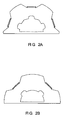
- Fig. 2A and Fig. 2B are top views of other types of the heat-dissipating unit of the heat-dissipating structure according to the present invention.
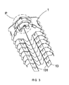
- Fig. 3 is a perspective diagram of the heat-dissipating structure formed by assembling a plurality of heat dissipating units as shown in Fig. 1 A;
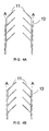
- Fig. 4A and Fig. 4B are schematic diagrams showing different stacked types of a plurality of the bending portions of the heat-dissipating structure shown in Fig. 3 ;
- Fig. 5A is a perspective diagram of the heat-dissipating structure of the present invention and the light source before being assembled;
- Fig. 5B is a perspective diagram of the heat-dissipating structure of the present invention and the light source after being assembled;
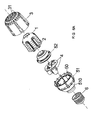
- Fig. 6A is an exploded view of the illuminating device according to the present invention before being assembled
- Fig. 6B is a perspective view of the illuminating device of the present invention after being assembled
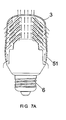
- Fig. 7A is a schematic diagram showing the airflow of the illuminating device of the present invention of Fig. 6B while being in vertical position;
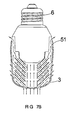
- Fig. 7B is a schematic diagram showing the airflow of the illuminating device of the present invention of Fig. 6B while being in inverse position;
- Fig. 7C is a schematic diagram showing the airflow of the illuminating device of the present invention of Fig. 6B while being in horizontal position;
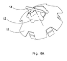
- Fig. 8A is a perspective view of another type of the heat-dissipating unit according to the present invention.
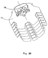
- Fig. 8B is a perspective diagram of the heat-dissipating structure formed by assembling a plurality of heat dissipating units as shown in Fig. 8A .
- the heat-dissipating structure includes one or a plurality of heat-dissipating units stacked together, and the heat-dissipating structure can provide multi-directional natural convection.
- the heat-dissipating unit is preferably formed by metal stamping, and can be made of various material with different thickness to meet the real requirement.
- the heat-dissipating unit includes a cone-like portion 11 with an opening 12 and a plurality of protrusions 13 connected to the edge of the cone-like portion 11.
- the heat-dissipating unit can be an umbrella-shaped pyramid structure or conoid structure as shown in Fig. 1A and Fig. 1B .
- the heat-dissipating unit can be also a cone-like unsymmetrical structure as shown in Fig. 2A and Fig. 2B .
- each protrusion 13 of the heat-dissipating unit has two fasteners 131 disposed on its both sides, respectively.
- the protrusion 13 has a stepped bending portion with a through hole 132 on its surface, and the through hole 132 can accelerate the movement of airflow.
- the fastener 131 and the through hole 132 are optionally used depending on the product demands.
- the heat-dissipating unit can be symmetrically or unsymmetrically designed with two bending portions, three bending portions or six bending portions, etc.
- the bending portion is attached by the heat source for transmitting heat to the cone-like radiating surface.
- the protrusion 13 of the heat-dissipating unit is a stepped bending portion without through hole.
- the surface of the heat-dissipating unit can be further processed by surface treatment or provided with a microstructure.
- the microstructure can be formed by a physical or chemical process such as the anodic treatment or coating a material with high heat radiation, for increasing the heat-dissipating area and enhancing heat-radiating effect.
- the heat-dissipating unit further includes a plurality of apertures 14, as shown in Fig. 1A , for increasing the heat-dissipating area and guiding the airflow to the central opening 12.
- the cone-like portion 11 can be formed by a plurality of fins as shown in Fig. 1A , or a single annular fin as shown in Fig. 1B .
- the chimney-shaped heat-dissipating structure can be formed as shown in Fig. 3 .
- the bending portions close to each other and form a plane A as shown in Fig. 4A and Fig. 4B .
- the plane A allows the light source to be disposed thereon, and serves as a medium of the heat transmission.
- the bending portion can be designed as a bending portion with height difference or a stepped bending portion, and the height difference of one bending portion can receive another bending portion as shown in Fig. 4A .
- the bending portion can be also a planar bending portion as shown in Fig. 4B .
- the bending portion can be provided with a fastener 131 for positioning and connecting with the adjacent bending portion as shown in Fig. 3 .
- the plurality of the heat-dissipating units can position and connect to each other while being stacked together.
- the openings of the plurality of the heat-dissipating units are linked together and form a central airflow passage P as shown in Fig. 3 .
- the airflow passage P can accelerate movement of the airflow passing through the cone-like surface of the heat-dissipating unit because of the structural characteristic.
- a heat-dissipating structure includes a plurality of heat-dissipating units stacked together. While the heat-dissipating units are stacked together, the bending portions close to each other to form a plane.
- the heat-dissipating unit with N bending portions will form N zonal planes A, and N light sources 2 can be attached on the zonal planes A, respectively.
- the light source can be a semiconductor light source such as a light emitting diode (LED), a laser diode or an organic light emitting diode (OLED).
- the heat-dissipating area of the umbrella-shaped cone-like heat-dissipating unit is larger than that of the conventional heat sink.
- the heat generated from the light source can be transmitted to the cone-like heat-dissipating surface rapidly by heat conduction, and the multi-directional airflow can be guided to surface by heat convection.
- the heat is dissipated outside through the airflow convection formed by physical principle of heat airflow moving upward.
- an embodiment of the illuminating device includes a combination of the heat-dissipating structure 1 and the light source 2 as shown in Fig. 5B , a transparent cover 3, a securing structure, an electric component 4 and a power connector 6.
- the power connector 6 is E10/E11, E26/E27 or E39/E40.
- the light source 2 is an alternating current LED, the electric component 4 can be omitted.
- the transparent cover 3 further includes a plurality of vents disposed thereon circumambiently for increasing airflow and decreasing temperature to achieve the effect of cooling the heat-dissipating structure.
- the securing structure includes a first part 51 and a second part 52, and the electric component 4 can be disposed in a space 50 defined between the first part 51 and the second part 52.
- the combination of the heat-dissipating structure 1 and the light source 2 can be fixed on the surface of the second part 52 by engagement or other equivalent way.
- a plurality of through holes 510 can be disposed on the first part 51.
- a chimney effect is formed in the central airflow passage P.
- the chimney effect is useful to enhance the effect of convection and heat dissipation.
- Fig. 7A showing the illuminating device while being in vertical position.
- the cold airflow passes through the vents of the transparent cover 3, the first part 51, and the gaps between the heat-dissipating units, and converges together in the central airflow passage P finally.
- the airflow passes through the cone-like surface of the heat-dissipating structure and dissipates heat by the way of heat transmission and heat convection.
- Fig. 7A showing the illuminating device while being in vertical position.
- the cold airflow passes through the vents of the transparent cover 3, the first part 51, and the gaps between the heat-dissipating units, and converges together in the central airflow passage P finally.
- the airflow passes through the cone-like surface of the heat-dissipating structure and dissipates heat by the way of heat
- the illuminating device in the inverse position, and the direction of the airflow is contrary with that of Fig. 7A . Additionally, while the illuminating device is in horizontal position, the airflow can also pass through the cone-like surface of the heat-dissipating structure successfully. The airflow enters the central airflow passage of the illuminating device from underside vents, and is discharged from upside vents as shown in Fig. 7C . Therefore, the heat-dissipating structure of the illuminating device according to the present invention can be used to dissipate heat in all position.
- Fig. 8A and Fig. 8B respectively showing another type of the heat-dissipating unit and the heat-dissipating structure of the present invention.
- the structure of the heat-dissipating unit is similar to Fig. 1B except that the heat dissipating unit further includes a rod portion 14 located across the opening 12 and connected to the cone-like portion 11 as shown in Fig. 8A .
- the rod portion 14 is used for increasing the heat-dissipating area and guiding the airflow.
- the rod portion 14 is disposed in various angles for guiding the airflow while the heat-dissipating units are stacked together as shown in Fig. 8B .
- the rod portions of the heat-dissipating units are laid across each other so that the cross section of central airflow passage is divided into several parts for guiding the airflow respectively to improve heat-dissipating efficiency.
- the illuminating device and the heat-dissipating structure of the present invention provide multi-directional natural convection and can be configured in any position.
- the present invention achieves the chimney-like effect to accelerate the dissipation of heat through the central airflow passage.
- the heat-dissipating structure of the present invention is made by stamping thin metals and stacking them together.
- the heat-dissipating structure of the present invention has the advantages of a large increase of heat-dissipating area, a reduction of material usage, and the conservation of energy and cost.
- the heat-dissipating structure of the present invention includes a plurality of heat-dissipating units stacked together with bending portions. While the heat-dissipating units are stacked together, the multi-side bending portions of adjacent heat-dissipating units close to each other to form a plane for allowing the light source to be disposed thereon.
- the plurality of light sources are disposed on the surface of the heat-dissipating structure circumambiently so that they can illuminate in 360° to achieve the best lighting level rather than being limited to a single direction.
Landscapes
- Engineering & Computer Science (AREA)
- General Engineering & Computer Science (AREA)
- Physics & Mathematics (AREA)
- Microelectronics & Electronic Packaging (AREA)
- Optics & Photonics (AREA)
- Arrangement Of Elements, Cooling, Sealing, Or The Like Of Lighting Devices (AREA)
- Non-Portable Lighting Devices Or Systems Thereof (AREA)
Abstract
Description
- This Non-provisional application claims priority under 35 U.S.C §119(a) on Patent Application No(s).
097111253 - The present invention relates to an illuminating device and a heat-dissipating structure thereof, and in particular to an illuminating device having a cone-like heat-dissipating structure.
- Traditionally, heat sinks are made by aluminum extrusion, metal die casting or metal forging. However, such a manufacturing way has the disadvantages of high cost, overweight, complicated process, large volume, bad efficiency of natural convection, etc. Due to the above problems, another way is to utilize mechanical press to make several fins for being stacked together to constitute a heat sink. However, most of heat sinks are formed by stacked planar fins and such a design will be limited by its shape, so that the direction of the airflow will be limited to a direction in parallel to the stacked direction of fins. Thus, this kind of heat sink needs to be improved by adding a heat pipe or a fan to enhance heat-dissipating efficiency. Further, such kind of heat sink can not attain the purpose of multi-directional natural convection for heat dissipation. Moreover, the conventional light emitting diode (LED) lamp only emits from single side due to the limitation of shape and manufacturing way of the heat sink.
- In view of the foregoing, the invention is to provide an illuminating device and a heat-dissipating structure thereof.
- To achieve the above, the present invention discloses a heat-dissipating structure including a plurality of heat-dissipating units stacked together. Each heat-dissipating unit includes a cone-like portion with an opening and a plurality of protrusions connected to the cone-like portion, wherein at least one of the protrusions of one heat-dissipating unit is coupled to that of the adjacent heat-dissipating unit to form one or more zonal planes for allowing a light source to be disposed thereon to constitute the illuminating device, and the openings of the heat-dissipating units are linked together to form an airflow passage.
- The heat-dissipating unit is formed by metal stamping. Preferably, the heat-dissipating unit is a pyramid, a conoid or an umbrella-shaped unsymmetrical structure.
- Optionally, the protrusion has a fastener for positioning and connecting with the adjacent protrusion and a through hole for accelerating movement of the airflow. The protrusion has preferably a planar or stepped bending portion. The plurality of protrusions are symmetrically or unsymmetrically disposed on the edge of the cone-like portion.
- The surface of the heat-dissipating unit is processed physically or chemically for accelerating heat-radiation, for example but not limited to, the anodic treatment or the heat-radiating material coating. The surface of the heat-dissipating unit may also have a microstructure.
- The heat-dissipating unit further includes a plurality of apertures. The cone-like portion is formed by a plurality of fins or a single annular fin.
- Preferably , the heat source is a light emitting diode (LED), a laser diode, an organic light emitting diode (OLED) or a semiconductor light source.
- To achieve the above, another heat-dissipating structure of the present invention comprises at least a heat-dissipating unit including a cone-like portion with an opening and at least a protrusion connected to the cone-like portion.
- To achieve the above, an illuminating device of the present invention comprises a light source and a heat-dissipating structure including a plurality of heat-dissipating units stacked together. Each heat-dissipating unit includes a cone-like portion with an opening and at least a protrusion connected to the cone-like portion. The light source is disposed on a plane formed by the protrusions.
- Wherein the light source is preferably a light emitting diode, a laser diode, an organic light emitting diode, or a semiconductor light source.
- The illuminating device further comprises a transparent housing disposed outside of the heat-dissipating structure and the light source. The transparent housing has one or more vents optionally.
- The illuminating device further comprises a securing structure for fastening the heat-dissipating structure. The securing structure comprises a first part and a second part, and the illuminating device further comprises an electric component disposed in a space formed between the first part and the second part of the securing structure. Of course, the electric component is not needed if the light source is an alternating current LED. The first part has a plurality of through holes optionally.
- The illuminating device further comprises a power connector and the type of the power connector is E10/E11, E26/E27, or E39/E40.
- The present invention is more fully understood by reading the subsequent detailed description and examples with references made to the accompanying drawings, wherein:
-
Fig. 1A and Fig. 1B are perspective diagrams of different types of the heat-dissipating units of the heat-dissipating structure according to the present invention; -
Fig. 2A and Fig. 2B are top views of other types of the heat-dissipating unit of the heat-dissipating structure according to the present invention; -
Fig. 3 is a perspective diagram of the heat-dissipating structure formed by assembling a plurality of heat dissipating units as shown inFig. 1 A; -
Fig. 4A and Fig. 4B are schematic diagrams showing different stacked types of a plurality of the bending portions of the heat-dissipating structure shown inFig. 3 ; -
Fig. 5A is a perspective diagram of the heat-dissipating structure of the present invention and the light source before being assembled; -
Fig. 5B is a perspective diagram of the heat-dissipating structure of the present invention and the light source after being assembled; -
Fig. 6A is an exploded view of the illuminating device according to the present invention before being assembled; -
Fig. 6B is a perspective view of the illuminating device of the present invention after being assembled; -
Fig. 7A is a schematic diagram showing the airflow of the illuminating device of the present invention ofFig. 6B while being in vertical position; -
Fig. 7B is a schematic diagram showing the airflow of the illuminating device of the present invention ofFig. 6B while being in inverse position; -
Fig. 7C is a schematic diagram showing the airflow of the illuminating device of the present invention ofFig. 6B while being in horizontal position; -
Fig. 8A is a perspective view of another type of the heat-dissipating unit according to the present invention; and -
Fig. 8B is a perspective diagram of the heat-dissipating structure formed by assembling a plurality of heat dissipating units as shown inFig. 8A . - The present invention will be apparent from the following detailed description, which proceeds with reference to the accompanying drawings, wherein the same references relate to the same elements.
- According to the present invention, the heat-dissipating structure includes one or a plurality of heat-dissipating units stacked together, and the heat-dissipating structure can provide multi-directional natural convection. The heat-dissipating unit is preferably formed by metal stamping, and can be made of various material with different thickness to meet the real requirement. The heat-dissipating unit includes a cone-
like portion 11 with anopening 12 and a plurality ofprotrusions 13 connected to the edge of the cone-like portion 11. The heat-dissipating unit can be an umbrella-shaped pyramid structure or conoid structure as shown inFig. 1A and Fig. 1B . The heat-dissipating unit can be also a cone-like unsymmetrical structure as shown inFig. 2A and Fig. 2B . - Referring to
Fig. 1A , eachprotrusion 13 of the heat-dissipating unit has twofasteners 131 disposed on its both sides, respectively. Theprotrusion 13 has a stepped bending portion with a throughhole 132 on its surface, and the throughhole 132 can accelerate the movement of airflow. Certainly, thefastener 131 and the throughhole 132 are optionally used depending on the product demands. - According to the user's requirement, the heat-dissipating unit can be symmetrically or unsymmetrically designed with two bending portions, three bending portions or six bending portions, etc. The bending portion is attached by the heat source for transmitting heat to the cone-like radiating surface. As shown in
Fig. 1B , theprotrusion 13 of the heat-dissipating unit is a stepped bending portion without through hole. - In addition, the surface of the heat-dissipating unit can be further processed by surface treatment or provided with a microstructure. The microstructure can be formed by a physical or chemical process such as the anodic treatment or coating a material with high heat radiation, for increasing the heat-dissipating area and enhancing heat-radiating effect.
- Moreover, the heat-dissipating unit further includes a plurality of
apertures 14, as shown inFig. 1A , for increasing the heat-dissipating area and guiding the airflow to thecentral opening 12. The cone-like portion 11 can be formed by a plurality of fins as shown inFig. 1A , or a single annular fin as shown inFig. 1B . - When the heat-dissipating units, as shown in
Fig. 1A , are stacked together, the chimney-shaped heat-dissipating structure can be formed as shown inFig. 3 . While the heat-dissipating units are stacked together, the bending portions close to each other and form a plane A as shown inFig. 4A and Fig. 4B . The plane A allows the light source to be disposed thereon, and serves as a medium of the heat transmission. The bending portion can be designed as a bending portion with height difference or a stepped bending portion, and the height difference of one bending portion can receive another bending portion as shown inFig. 4A . The bending portion can be also a planar bending portion as shown inFig. 4B . Optionally, the bending portion can be provided with afastener 131 for positioning and connecting with the adjacent bending portion as shown inFig. 3 . Thus, the plurality of the heat-dissipating units can position and connect to each other while being stacked together. - After assembling the plurality of the heat-dissipating units as shown above, the openings of the plurality of the heat-dissipating units are linked together and form a central airflow passage P as shown in
Fig. 3 . There is a gap between two adjacent cone-like portions for allowing the airflow to pass therethrough. Therefore, the cold airflow will pass through the surface of the heat-dissipating structure and take heat away. The airflow passage P can accelerate movement of the airflow passing through the cone-like surface of the heat-dissipating unit because of the structural characteristic. - Referring to
Fig. 5A andFig. 5B , a heat-dissipating structure includes a plurality of heat-dissipating units stacked together. While the heat-dissipating units are stacked together, the bending portions close to each other to form a plane. The heat-dissipating unit with N bending portions will form N zonal planes A, and Nlight sources 2 can be attached on the zonal planes A, respectively. The light source can be a semiconductor light source such as a light emitting diode (LED), a laser diode or an organic light emitting diode (OLED). - According to the present invention, the heat-dissipating area of the umbrella-shaped cone-like heat-dissipating unit is larger than that of the conventional heat sink. Thus, the heat generated from the light source can be transmitted to the cone-like heat-dissipating surface rapidly by heat conduction, and the multi-directional airflow can be guided to surface by heat convection. The heat is dissipated outside through the airflow convection formed by physical principle of heat airflow moving upward.
- Referring to
Fig. 6A andFig. 6B , an embodiment of the illuminating device according to the present invention includes a combination of the heat-dissipatingstructure 1 and thelight source 2 as shown inFig. 5B , atransparent cover 3, a securing structure, anelectric component 4 and apower connector 6. Thepower connector 6 is E10/E11, E26/E27 or E39/E40. Of course, if thelight source 2 is an alternating current LED, theelectric component 4 can be omitted. Thetransparent cover 3 further includes a plurality of vents disposed thereon circumambiently for increasing airflow and decreasing temperature to achieve the effect of cooling the heat-dissipating structure. Certainly, thesevents 31 are optionally used depending on the product demands. The securing structure includes afirst part 51 and asecond part 52, and theelectric component 4 can be disposed in aspace 50 defined between thefirst part 51 and thesecond part 52. The combination of the heat-dissipatingstructure 1 and thelight source 2 can be fixed on the surface of thesecond part 52 by engagement or other equivalent way. Optionally, a plurality of throughholes 510 can be disposed on thefirst part 51. - While the illuminating device, as shown in
Fig. 6B , is configured in vertical or inverse position, a chimney effect is formed in the central airflow passage P. The chimney effect is useful to enhance the effect of convection and heat dissipation. Please refer toFig. 7A showing the illuminating device while being in vertical position. The cold airflow passes through the vents of thetransparent cover 3, thefirst part 51, and the gaps between the heat-dissipating units, and converges together in the central airflow passage P finally. Thus, the airflow passes through the cone-like surface of the heat-dissipating structure and dissipates heat by the way of heat transmission and heat convection. Please refer toFig. 7B the illuminating device in the inverse position, and the direction of the airflow is contrary with that ofFig. 7A . Additionally, while the illuminating device is in horizontal position, the airflow can also pass through the cone-like surface of the heat-dissipating structure successfully. The airflow enters the central airflow passage of the illuminating device from underside vents, and is discharged from upside vents as shown inFig. 7C . Therefore, the heat-dissipating structure of the illuminating device according to the present invention can be used to dissipate heat in all position. - Please refer to
Fig. 8A andFig. 8B respectively showing another type of the heat-dissipating unit and the heat-dissipating structure of the present invention. The structure of the heat-dissipating unit is similar toFig. 1B except that the heat dissipating unit further includes arod portion 14 located across theopening 12 and connected to the cone-like portion 11 as shown inFig. 8A . Therod portion 14 is used for increasing the heat-dissipating area and guiding the airflow. Therod portion 14 is disposed in various angles for guiding the airflow while the heat-dissipating units are stacked together as shown inFig. 8B . Preferably, the rod portions of the heat-dissipating units are laid across each other so that the cross section of central airflow passage is divided into several parts for guiding the airflow respectively to improve heat-dissipating efficiency. - In conclusion, the illuminating device and the heat-dissipating structure of the present invention provide multi-directional natural convection and can be configured in any position. Thus the present invention achieves the chimney-like effect to accelerate the dissipation of heat through the central airflow passage. Moreover, the heat-dissipating structure of the present invention is made by stamping thin metals and stacking them together. Compared with the conventional heat sinks, the heat-dissipating structure of the present invention has the advantages of a large increase of heat-dissipating area, a reduction of material usage, and the conservation of energy and cost.
- Furthermore, the heat-dissipating structure of the present invention includes a plurality of heat-dissipating units stacked together with bending portions. While the heat-dissipating units are stacked together, the multi-side bending portions of adjacent heat-dissipating units close to each other to form a plane for allowing the light source to be disposed thereon. The plurality of light sources are disposed on the surface of the heat-dissipating structure circumambiently so that they can illuminate in 360° to achieve the best lighting level rather than being limited to a single direction.
- While the invention has been described in connection with what is presently considered to be the most practical and preferred embodiment, it is to be understood that the invention is not limited to the disclosed embodiments, but, on the contrary, is intended to accommodate various modifications and equivalent arrangements included within the spirit and scope of the appended claims.
Claims (22)
- A heat-dissipating structure comprising a plurality of heat-dissipating units stacked together, wherein each heat-dissipating unit comprises:a cone-like portion with an opening; anda plurality of protrusions connected to the cone-like portion, wherein at least one of the protrusions of one heat-dissipating unit is coupled to that of the adjacent heat-dissipating unit to form a plane for allowing a heat source to be disposed thereon, and the openings of the heat-dissipating units are linked together to form an airflow passage.
- A heat-dissipating structure comprising:at least a heat-dissipating unit including a cone-like portion with an opening; andat least a protrusion connected to the cone-like portion.
- The heat-dissipating structure of claim 1 or 2, wherein the heat-dissipating unit is formed by metal stamping.
- The heat-dissipating structure of claim 1 or 2, wherein the heat-dissipating unit is a pyramid, a conoid, or an umbrella-shaped unsymmetrical structure.
- The heat-dissipating structure of claim 1 or 2, wherein the protrusion has a fastener for positioning and connecting with the adjacent protrusion.
- The heat-dissipating structure of claim 1 or 2, wherein the protrusion has a planar or stepped bending portion.
- The heat-dissipating structure of claim 1 or 2, wherein the surface of the protrusion has a through hole for accelerating movement of the airflow.
- The heat-dissipating structure of claim 1 or 2, wherein the plurality of protrusions are symmetrically or unsymmetrically disposed on the edge of the cone-like portion.
- The heat-dissipating structure of claim 1 or 2, wherein the surface of the heat-dissipating unit is processed physically or chemically for accelerating heat-radiation.
- The heat-dissipating structure of claim 1 or 2, wherein the surface of the heat-dissipating unit is processed with anodic treatment or coated with a high heat-radiating material or has a microstructure.
- The heat-dissipating structure of claim 1 or 2, wherein the heat-dissipating unit further includes a plurality of apertures.
- The heat-dissipating structure of claim 1 or 2, wherein the cone-like portion is formed by a plurality of fins or a single annular fin.
- The heat-dissipating structure of claim 1 or 2, wherein there is a gap between two adjacent cone-like portions for allowing the airflow to pass therethrough.
- The heat-dissipating structure of claim 1 or 2, wherein the heat-dissipating unit further includes a rod portion located across the opening and connected to the cone-like portion.
- The heat-dissipating structure of claim 14, wherein the rod portions of the heat-dissipating units are laid across each other.
- An illuminating device comprising:a heat-dissipating structure comprising one or more heat-dissipating units stacked together, the heat-dissipating unit comprising a cone-like portion with an opening; and a protrusion connected to the cone-like portion; anda light source disposed on a plane formed by the protrusion.
- The illuminating device of claim 16, further comprising a transparent cover disposed outside of the heat-dissipating structure and the light source.
- The illuminating device of claim 17, wherein the transparent cover has one or more vents.
- The illuminating device of claim 16, further comprising a securing structure used to fasten the heat-dissipating structure.
- The illuminating device of claim 19, wherein the securing structure comprises a first part and a second part, and the illuminating device further comprises an electric component disposed in a space formed between the first part and the second part of the securing structure.
- The illuminating device of claim 19, wherein the securing structure has one or more through holes.
- The illuminating device of claim 16, further comprising a power connector.
Applications Claiming Priority (1)
| Application Number | Priority Date | Filing Date | Title |
|---|---|---|---|
| TW097111253A TWI340810B (en) | 2008-03-28 | 2008-03-28 | Illuminating device and heat-dissipating structure thereof |
Publications (2)
| Publication Number | Publication Date |
|---|---|
| EP2105652A1 true EP2105652A1 (en) | 2009-09-30 |
| EP2105652B1 EP2105652B1 (en) | 2011-10-19 |
Family
ID=40672230
Family Applications (1)
| Application Number | Title | Priority Date | Filing Date |
|---|---|---|---|
| EP08010989A Not-in-force EP2105652B1 (en) | 2008-03-28 | 2008-06-17 | Illuminating device and heat-dissipating structure thereof |
Country Status (5)
| Country | Link |
|---|---|
| US (1) | US8382330B2 (en) |
| EP (1) | EP2105652B1 (en) |
| JP (1) | JP4677013B2 (en) |
| AT (1) | ATE529688T1 (en) |
| TW (1) | TWI340810B (en) |
Cited By (4)
| Publication number | Priority date | Publication date | Assignee | Title |
|---|---|---|---|---|
| CN102345844A (en) * | 2010-07-30 | 2012-02-08 | 欧司朗有限公司 | Cooling device and manufacturing method thereof as well as LED (light emitting diode) illumination device with cooling device |
| US8382330B2 (en) | 2008-03-28 | 2013-02-26 | Delta Electronics, Inc. | Illuminating device and heat-dissipating structure thereof |
| EP2578932A4 (en) * | 2010-06-07 | 2013-06-12 | Tae-Kyu Han | Lighting device |
| CN109210520A (en) * | 2017-07-03 | 2019-01-15 | 法雷奥北美有限公司 | Device and method for placing light source on a heat sink |
Families Citing this family (15)
| Publication number | Priority date | Publication date | Assignee | Title |
|---|---|---|---|---|
| GB0809650D0 (en) * | 2008-05-29 | 2008-07-02 | Integration Technology Ltd | LED Device and arrangement |
| TW201005213A (en) * | 2008-07-24 | 2010-02-01 | Advanced Optoelectronic Tech | Passive heat sink and LED illumination device using the same |
| DE102009029839A1 (en) * | 2009-04-03 | 2010-10-07 | Osram Opto Semiconductors Gmbh | Lamp and lamp with such a light source |
| TW201200793A (en) * | 2010-06-29 | 2012-01-01 | Foxsemicon Integrated Tech Inc | Room illumination apparatus |
| JP5557105B2 (en) * | 2010-09-10 | 2014-07-23 | 東芝ライテック株式会社 | Lamp with lamp and lighting equipment |
| US8487518B2 (en) * | 2010-12-06 | 2013-07-16 | 3M Innovative Properties Company | Solid state light with optical guide and integrated thermal guide |
| US20120026723A1 (en) * | 2011-02-01 | 2012-02-02 | Switch Bulb Company, Inc. | Omni-directional channeling of liquids for passive convection in led bulbs |
| JP5921863B2 (en) * | 2011-12-01 | 2016-05-24 | 岩崎電気株式会社 | lamp |
| JP5513472B2 (en) * | 2011-12-15 | 2014-06-04 | 常盤電業株式会社 | Lamp unit and signal lamp using the same |
| KR101318141B1 (en) | 2012-08-30 | 2013-10-18 | 한국에너지기술연구원 | Radiant heat structure of fish luring light having led and fish luring light having led having the same |
| CN106662321A (en) | 2014-06-03 | 2017-05-10 | 飞利浦灯具控股公司 | Luminaire heat sink |
| KR101791575B1 (en) * | 2015-04-06 | 2017-10-30 | 주식회사 휘일라이팅 | A Layered Heat sink and LED Lamp module using it |
| CN106352249B (en) * | 2016-08-18 | 2020-02-07 | 东莞市闻誉实业有限公司 | High-efficiency heat-dissipation LED lamp |
| CN106322132B (en) * | 2016-08-19 | 2020-03-24 | 东莞市闻誉实业有限公司 | LED lighting lamp |
| US10767816B1 (en) * | 2019-04-24 | 2020-09-08 | Xiamen Eco Lighting Co. Ltd. | Light bulb apparatus |
Citations (3)
| Publication number | Priority date | Publication date | Assignee | Title |
|---|---|---|---|---|
| WO2007053939A1 (en) | 2005-11-09 | 2007-05-18 | Tir Technology Lp. | Passive thermal management system |
| US20070159828A1 (en) | 2006-01-09 | 2007-07-12 | Ceramate Technical Co., Ltd. | Vertical LED lamp with a 360-degree radiation and a high cooling efficiency |
| EP1950491A1 (en) * | 2007-01-26 | 2008-07-30 | Piper Lux S.r.l. | LED spotlight |
Family Cites Families (23)
| Publication number | Priority date | Publication date | Assignee | Title |
|---|---|---|---|---|
| US5172975A (en) | 1992-04-27 | 1992-12-22 | Mole-Richardson Co. | Light assembly with ventilated housing |
| US5537301A (en) * | 1994-09-01 | 1996-07-16 | Pacific Scientific Company | Fluorescent lamp heat-dissipating apparatus |
| JP3012632B1 (en) * | 1999-01-14 | 2000-02-28 | 日本電気移動通信株式会社 | Outdoor housing |
| MY132881A (en) * | 2000-04-05 | 2007-10-31 | Advance Ind Sdn Bhd | Bollard light |
| CA2424436A1 (en) * | 2000-10-10 | 2002-04-18 | Gye-Seon Lee | Led lamp for signal light |
| US6483254B2 (en) * | 2000-12-20 | 2002-11-19 | Honeywell International Inc. | Led strobe light |
| US7093958B2 (en) * | 2002-04-09 | 2006-08-22 | Osram Sylvania Inc. | LED light source assembly |
| US6974227B2 (en) * | 2002-08-27 | 2005-12-13 | Hung-Chi Tsai | Supporting structure for Christmas light decoration |
| CN2637885Y (en) * | 2003-02-20 | 2004-09-01 | 高勇 | LED lamp bulb with luminous curved surface |
| US7658510B2 (en) * | 2004-08-18 | 2010-02-09 | Remco Solid State Lighting Inc. | System and method for power control in a LED luminaire |
| US7387403B2 (en) * | 2004-12-10 | 2008-06-17 | Paul R. Mighetto | Modular lighting apparatus |
| US7267453B2 (en) * | 2005-04-07 | 2007-09-11 | Hung-Shen Chang | Multifunctional stick assembly |
| US7455430B2 (en) * | 2006-01-06 | 2008-11-25 | Advanced Thermal Devices, Inc. | Lighting device with a multiple layer cooling structure |
| US7604380B2 (en) * | 2006-06-30 | 2009-10-20 | Dialight Corporation | Apparatus for using heat pipes in controlling temperature of an LED light unit |
| US7482632B2 (en) * | 2006-07-12 | 2009-01-27 | Hong Kong Applied Science And Technology Research Institute Co., Ltd. | LED assembly and use thereof |
| US7798684B2 (en) * | 2007-04-06 | 2010-09-21 | Genlyte Thomas Group Llc | Luminaire system with thermal chimney effect |
| CN101329054B (en) * | 2007-06-22 | 2010-09-29 | 富准精密工业(深圳)有限公司 | LED lamp with heat radiation structure |
| US7568817B2 (en) * | 2007-06-27 | 2009-08-04 | Fu Zhun Precision Industry (Shen Zhen) Co., Ltd. | LED lamp |
| US7607802B2 (en) * | 2007-07-23 | 2009-10-27 | Tamkang University | LED lamp instantly dissipating heat as effected by multiple-layer substrates |
| CN101424394B (en) * | 2007-11-02 | 2010-09-08 | 富准精密工业(深圳)有限公司 | Heat radiating device and led lamp using the same |
| TWI340810B (en) | 2008-03-28 | 2011-04-21 | Delta Electronics Inc | Illuminating device and heat-dissipating structure thereof |
| CN101545621B (en) | 2008-03-28 | 2011-06-29 | 台达电子工业股份有限公司 | Lighting device and its heat dissipation structure |
| US7874692B2 (en) * | 2008-06-05 | 2011-01-25 | Fu Zhun Precision Industry (Shen Zhen) Co., Ltd. | LED lamp |
-
2008
- 2008-03-28 TW TW097111253A patent/TWI340810B/en not_active IP Right Cessation
- 2008-06-17 EP EP08010989A patent/EP2105652B1/en not_active Not-in-force
- 2008-06-17 AT AT08010989T patent/ATE529688T1/en active
- 2008-06-27 JP JP2008169536A patent/JP4677013B2/en not_active Expired - Fee Related
- 2008-06-27 US US12/163,144 patent/US8382330B2/en active Active
Patent Citations (3)
| Publication number | Priority date | Publication date | Assignee | Title |
|---|---|---|---|---|
| WO2007053939A1 (en) | 2005-11-09 | 2007-05-18 | Tir Technology Lp. | Passive thermal management system |
| US20070159828A1 (en) | 2006-01-09 | 2007-07-12 | Ceramate Technical Co., Ltd. | Vertical LED lamp with a 360-degree radiation and a high cooling efficiency |
| EP1950491A1 (en) * | 2007-01-26 | 2008-07-30 | Piper Lux S.r.l. | LED spotlight |
Cited By (5)
| Publication number | Priority date | Publication date | Assignee | Title |
|---|---|---|---|---|
| US8382330B2 (en) | 2008-03-28 | 2013-02-26 | Delta Electronics, Inc. | Illuminating device and heat-dissipating structure thereof |
| EP2578932A4 (en) * | 2010-06-07 | 2013-06-12 | Tae-Kyu Han | Lighting device |
| CN102345844A (en) * | 2010-07-30 | 2012-02-08 | 欧司朗有限公司 | Cooling device and manufacturing method thereof as well as LED (light emitting diode) illumination device with cooling device |
| WO2012013600A3 (en) * | 2010-07-30 | 2012-04-05 | Osram Ag | A cooling device and led lighting apparatus comprising the same and a method of manufacturing the cooling device |
| CN109210520A (en) * | 2017-07-03 | 2019-01-15 | 法雷奥北美有限公司 | Device and method for placing light source on a heat sink |
Also Published As
| Publication number | Publication date |
|---|---|
| EP2105652B1 (en) | 2011-10-19 |
| TWI340810B (en) | 2011-04-21 |
| JP2009245916A (en) | 2009-10-22 |
| ATE529688T1 (en) | 2011-11-15 |
| TW200940886A (en) | 2009-10-01 |
| JP4677013B2 (en) | 2011-04-27 |
| US8382330B2 (en) | 2013-02-26 |
| US20090244900A1 (en) | 2009-10-01 |
Similar Documents
| Publication | Publication Date | Title |
|---|---|---|
| EP2105652B1 (en) | Illuminating device and heat-dissipating structure thereof | |
| EP2128522A1 (en) | Illuminating device and heat-dissipating structure thereof | |
| US7748876B2 (en) | LED lamp with a heat sink assembly | |
| US8459841B2 (en) | Lamp assembly | |
| US20100026158A1 (en) | Heat dissipation structure of LED light | |
| EP2378184B1 (en) | Lamp assembly | |
| CN101545621B (en) | Lighting device and its heat dissipation structure | |
| JP6152647B2 (en) | heatsink | |
| US20100002453A1 (en) | Illuminating device and annular heat-dissipating structure thereof | |
| US20090135594A1 (en) | Heat dissipation device used in led lamp | |
| US20130051021A1 (en) | LED Bulb | |
| EP2997305B1 (en) | Lighting device and luminaire | |
| US20090279256A1 (en) | Heat-dissipating structure | |
| US20100243211A1 (en) | Heat dissipating structure of high power led projector lamp | |
| US20090321049A1 (en) | Radiating fin | |
| KR101031546B1 (en) | Heat dissipation structure of LED street lighting fixtures | |
| US11879629B2 (en) | LED light fixture with a heat sink having concentrically segmented fins | |
| KR101709669B1 (en) | Heat Sink Plate, and Heat Sink and LED Street Light manufacured using the Heat Sink Plates | |
| JP2014022314A (en) | Heat sink device and lighting device | |
| US20160084489A1 (en) | Heat sink having heat dissipating fin and lighting device | |
| JP6316399B2 (en) | Lighting device | |
| CN101598315B (en) | Lighting device and its heat dissipation structure | |
| WO2013114246A1 (en) | Heat dissipating structure and lighting device | |
| JP6939145B2 (en) | heat sink | |
| KR100882322B1 (en) | Lighting device with heat radiator |
Legal Events
| Date | Code | Title | Description |
|---|---|---|---|
| PUAI | Public reference made under article 153(3) epc to a published international application that has entered the european phase |
Free format text: ORIGINAL CODE: 0009012 |
|
| 17P | Request for examination filed |
Effective date: 20080617 |
|
| AK | Designated contracting states |
Kind code of ref document: A1 Designated state(s): AT BE BG CH CY CZ DE DK EE ES FI FR GB GR HR HU IE IS IT LI LT LU LV MC MT NL NO PL PT RO SE SI SK TR |
|
| AX | Request for extension of the european patent |
Extension state: AL BA MK RS |
|
| 17Q | First examination report despatched |
Effective date: 20100201 |
|
| AKX | Designation fees paid |
Designated state(s): AT BE BG CH CY CZ DE DK EE ES FI FR GB GR HR HU IE IS IT LI LT LU LV MC MT NL NO PL PT RO SE SI SK TR |
|
| REG | Reference to a national code |
Ref country code: DE Ref legal event code: R079 Ref document number: 602008010529 Country of ref document: DE Free format text: PREVIOUS MAIN CLASS: F21K0007000000 Ipc: F21K0099000000 |
|
| GRAP | Despatch of communication of intention to grant a patent |
Free format text: ORIGINAL CODE: EPIDOSNIGR1 |
|
| RIC1 | Information provided on ipc code assigned before grant |
Ipc: F21K 99/00 20100101AFI20110527BHEP Ipc: F21V 29/00 20060101ALI20110527BHEP |
|
| GRAS | Grant fee paid |
Free format text: ORIGINAL CODE: EPIDOSNIGR3 |
|
| GRAA | (expected) grant |
Free format text: ORIGINAL CODE: 0009210 |
|
| AK | Designated contracting states |
Kind code of ref document: B1 Designated state(s): AT BE BG CH CY CZ DE DK EE ES FI FR GB GR HR HU IE IS IT LI LT LU LV MC MT NL NO PL PT RO SE SI SK TR |
|
| REG | Reference to a national code |
Ref country code: GB Ref legal event code: FG4D |
|
| REG | Reference to a national code |
Ref country code: CH Ref legal event code: EP |
|
| REG | Reference to a national code |
Ref country code: IE Ref legal event code: FG4D |
|
| REG | Reference to a national code |
Ref country code: DE Ref legal event code: R096 Ref document number: 602008010529 Country of ref document: DE Effective date: 20120112 |
|
| REG | Reference to a national code |
Ref country code: NL Ref legal event code: VDEP Effective date: 20111019 |
|
| LTIE | Lt: invalidation of european patent or patent extension |
Effective date: 20111019 |
|
| PG25 | Lapsed in a contracting state [announced via postgrant information from national office to epo] |
Ref country code: NO Free format text: LAPSE BECAUSE OF FAILURE TO SUBMIT A TRANSLATION OF THE DESCRIPTION OR TO PAY THE FEE WITHIN THE PRESCRIBED TIME-LIMIT Effective date: 20120119 Ref country code: BE Free format text: LAPSE BECAUSE OF FAILURE TO SUBMIT A TRANSLATION OF THE DESCRIPTION OR TO PAY THE FEE WITHIN THE PRESCRIBED TIME-LIMIT Effective date: 20111019 Ref country code: LT Free format text: LAPSE BECAUSE OF FAILURE TO SUBMIT A TRANSLATION OF THE DESCRIPTION OR TO PAY THE FEE WITHIN THE PRESCRIBED TIME-LIMIT Effective date: 20111019 Ref country code: IS Free format text: LAPSE BECAUSE OF FAILURE TO SUBMIT A TRANSLATION OF THE DESCRIPTION OR TO PAY THE FEE WITHIN THE PRESCRIBED TIME-LIMIT Effective date: 20120219 |
|
| PG25 | Lapsed in a contracting state [announced via postgrant information from national office to epo] |
Ref country code: SE Free format text: LAPSE BECAUSE OF FAILURE TO SUBMIT A TRANSLATION OF THE DESCRIPTION OR TO PAY THE FEE WITHIN THE PRESCRIBED TIME-LIMIT Effective date: 20111019 Ref country code: HR Free format text: LAPSE BECAUSE OF FAILURE TO SUBMIT A TRANSLATION OF THE DESCRIPTION OR TO PAY THE FEE WITHIN THE PRESCRIBED TIME-LIMIT Effective date: 20111019 Ref country code: PT Free format text: LAPSE BECAUSE OF FAILURE TO SUBMIT A TRANSLATION OF THE DESCRIPTION OR TO PAY THE FEE WITHIN THE PRESCRIBED TIME-LIMIT Effective date: 20120220 Ref country code: GR Free format text: LAPSE BECAUSE OF FAILURE TO SUBMIT A TRANSLATION OF THE DESCRIPTION OR TO PAY THE FEE WITHIN THE PRESCRIBED TIME-LIMIT Effective date: 20120120 Ref country code: SI Free format text: LAPSE BECAUSE OF FAILURE TO SUBMIT A TRANSLATION OF THE DESCRIPTION OR TO PAY THE FEE WITHIN THE PRESCRIBED TIME-LIMIT Effective date: 20111019 Ref country code: NL Free format text: LAPSE BECAUSE OF FAILURE TO SUBMIT A TRANSLATION OF THE DESCRIPTION OR TO PAY THE FEE WITHIN THE PRESCRIBED TIME-LIMIT Effective date: 20111019 Ref country code: LV Free format text: LAPSE BECAUSE OF FAILURE TO SUBMIT A TRANSLATION OF THE DESCRIPTION OR TO PAY THE FEE WITHIN THE PRESCRIBED TIME-LIMIT Effective date: 20111019 |
|
| PG25 | Lapsed in a contracting state [announced via postgrant information from national office to epo] |
Ref country code: CY Free format text: LAPSE BECAUSE OF FAILURE TO SUBMIT A TRANSLATION OF THE DESCRIPTION OR TO PAY THE FEE WITHIN THE PRESCRIBED TIME-LIMIT Effective date: 20111019 |
|
| PG25 | Lapsed in a contracting state [announced via postgrant information from national office to epo] |
Ref country code: CZ Free format text: LAPSE BECAUSE OF FAILURE TO SUBMIT A TRANSLATION OF THE DESCRIPTION OR TO PAY THE FEE WITHIN THE PRESCRIBED TIME-LIMIT Effective date: 20111019 Ref country code: BG Free format text: LAPSE BECAUSE OF FAILURE TO SUBMIT A TRANSLATION OF THE DESCRIPTION OR TO PAY THE FEE WITHIN THE PRESCRIBED TIME-LIMIT Effective date: 20120119 Ref country code: EE Free format text: LAPSE BECAUSE OF FAILURE TO SUBMIT A TRANSLATION OF THE DESCRIPTION OR TO PAY THE FEE WITHIN THE PRESCRIBED TIME-LIMIT Effective date: 20111019 Ref country code: DK Free format text: LAPSE BECAUSE OF FAILURE TO SUBMIT A TRANSLATION OF THE DESCRIPTION OR TO PAY THE FEE WITHIN THE PRESCRIBED TIME-LIMIT Effective date: 20111019 Ref country code: SK Free format text: LAPSE BECAUSE OF FAILURE TO SUBMIT A TRANSLATION OF THE DESCRIPTION OR TO PAY THE FEE WITHIN THE PRESCRIBED TIME-LIMIT Effective date: 20111019 |
|
| PLBE | No opposition filed within time limit |
Free format text: ORIGINAL CODE: 0009261 |
|
| STAA | Information on the status of an ep patent application or granted ep patent |
Free format text: STATUS: NO OPPOSITION FILED WITHIN TIME LIMIT |
|
| PG25 | Lapsed in a contracting state [announced via postgrant information from national office to epo] |
Ref country code: PL Free format text: LAPSE BECAUSE OF FAILURE TO SUBMIT A TRANSLATION OF THE DESCRIPTION OR TO PAY THE FEE WITHIN THE PRESCRIBED TIME-LIMIT Effective date: 20111019 Ref country code: RO Free format text: LAPSE BECAUSE OF FAILURE TO SUBMIT A TRANSLATION OF THE DESCRIPTION OR TO PAY THE FEE WITHIN THE PRESCRIBED TIME-LIMIT Effective date: 20111019 Ref country code: IT Free format text: LAPSE BECAUSE OF FAILURE TO SUBMIT A TRANSLATION OF THE DESCRIPTION OR TO PAY THE FEE WITHIN THE PRESCRIBED TIME-LIMIT Effective date: 20111019 |
|
| 26N | No opposition filed |
Effective date: 20120720 |
|
| REG | Reference to a national code |
Ref country code: DE Ref legal event code: R097 Ref document number: 602008010529 Country of ref document: DE Effective date: 20120720 |
|
| PG25 | Lapsed in a contracting state [announced via postgrant information from national office to epo] |
Ref country code: MC Free format text: LAPSE BECAUSE OF NON-PAYMENT OF DUE FEES Effective date: 20120630 |
|
| REG | Reference to a national code |
Ref country code: CH Ref legal event code: PL |
|
| REG | Reference to a national code |
Ref country code: CH Ref legal event code: PL |
|
| REG | Reference to a national code |
Ref country code: IE Ref legal event code: MM4A |
|
| PG25 | Lapsed in a contracting state [announced via postgrant information from national office to epo] |
Ref country code: LI Free format text: LAPSE BECAUSE OF NON-PAYMENT OF DUE FEES Effective date: 20120630 Ref country code: IE Free format text: LAPSE BECAUSE OF NON-PAYMENT OF DUE FEES Effective date: 20120617 Ref country code: CH Free format text: LAPSE BECAUSE OF NON-PAYMENT OF DUE FEES Effective date: 20120630 Ref country code: ES Free format text: LAPSE BECAUSE OF FAILURE TO SUBMIT A TRANSLATION OF THE DESCRIPTION OR TO PAY THE FEE WITHIN THE PRESCRIBED TIME-LIMIT Effective date: 20120130 |
|
| PG25 | Lapsed in a contracting state [announced via postgrant information from national office to epo] |
Ref country code: FI Free format text: LAPSE BECAUSE OF FAILURE TO SUBMIT A TRANSLATION OF THE DESCRIPTION OR TO PAY THE FEE WITHIN THE PRESCRIBED TIME-LIMIT Effective date: 20111019 |
|
| PG25 | Lapsed in a contracting state [announced via postgrant information from national office to epo] |
Ref country code: MT Free format text: LAPSE BECAUSE OF FAILURE TO SUBMIT A TRANSLATION OF THE DESCRIPTION OR TO PAY THE FEE WITHIN THE PRESCRIBED TIME-LIMIT Effective date: 20111019 |
|
| PG25 | Lapsed in a contracting state [announced via postgrant information from national office to epo] |
Ref country code: TR Free format text: LAPSE BECAUSE OF FAILURE TO SUBMIT A TRANSLATION OF THE DESCRIPTION OR TO PAY THE FEE WITHIN THE PRESCRIBED TIME-LIMIT Effective date: 20111019 |
|
| PG25 | Lapsed in a contracting state [announced via postgrant information from national office to epo] |
Ref country code: LU Free format text: LAPSE BECAUSE OF NON-PAYMENT OF DUE FEES Effective date: 20120617 |
|
| PG25 | Lapsed in a contracting state [announced via postgrant information from national office to epo] |
Ref country code: HU Free format text: LAPSE BECAUSE OF FAILURE TO SUBMIT A TRANSLATION OF THE DESCRIPTION OR TO PAY THE FEE WITHIN THE PRESCRIBED TIME-LIMIT Effective date: 20080617 |
|
| REG | Reference to a national code |
Ref country code: FR Ref legal event code: PLFP Year of fee payment: 9 |
|
| REG | Reference to a national code |
Ref country code: FR Ref legal event code: PLFP Year of fee payment: 10 |
|
| REG | Reference to a national code |
Ref country code: FR Ref legal event code: PLFP Year of fee payment: 11 |
|
| PGFP | Annual fee paid to national office [announced via postgrant information from national office to epo] |
Ref country code: FR Payment date: 20200625 Year of fee payment: 13 Ref country code: DE Payment date: 20200629 Year of fee payment: 13 |
|
| PGFP | Annual fee paid to national office [announced via postgrant information from national office to epo] |
Ref country code: GB Payment date: 20200629 Year of fee payment: 13 |
|
| PGFP | Annual fee paid to national office [announced via postgrant information from national office to epo] |
Ref country code: AT Payment date: 20200603 Year of fee payment: 13 |
|
| REG | Reference to a national code |
Ref country code: DE Ref legal event code: R119 Ref document number: 602008010529 Country of ref document: DE |
|
| REG | Reference to a national code |
Ref country code: AT Ref legal event code: MM01 Ref document number: 529688 Country of ref document: AT Kind code of ref document: T Effective date: 20210617 |
|
| GBPC | Gb: european patent ceased through non-payment of renewal fee |
Effective date: 20210617 |
|
| PG25 | Lapsed in a contracting state [announced via postgrant information from national office to epo] |
Ref country code: GB Free format text: LAPSE BECAUSE OF NON-PAYMENT OF DUE FEES Effective date: 20210617 Ref country code: DE Free format text: LAPSE BECAUSE OF NON-PAYMENT OF DUE FEES Effective date: 20220101 Ref country code: AT Free format text: LAPSE BECAUSE OF NON-PAYMENT OF DUE FEES Effective date: 20210617 |
|
| PG25 | Lapsed in a contracting state [announced via postgrant information from national office to epo] |
Ref country code: FR Free format text: LAPSE BECAUSE OF NON-PAYMENT OF DUE FEES Effective date: 20210630 |