EP2105611A1 - Fluid pressure pump unit - Google Patents
Fluid pressure pump unit Download PDFInfo
- Publication number
- EP2105611A1 EP2105611A1 EP09156159A EP09156159A EP2105611A1 EP 2105611 A1 EP2105611 A1 EP 2105611A1 EP 09156159 A EP09156159 A EP 09156159A EP 09156159 A EP09156159 A EP 09156159A EP 2105611 A1 EP2105611 A1 EP 2105611A1
- Authority
- EP
- European Patent Office
- Prior art keywords
- motor
- fluid pressure
- radiator
- pressure pump
- housing
- Prior art date
- Legal status (The legal status is an assumption and is not a legal conclusion. Google has not performed a legal analysis and makes no representation as to the accuracy of the status listed.)
- Granted
Links
Images

Classifications
-
- F—MECHANICAL ENGINEERING; LIGHTING; HEATING; WEAPONS; BLASTING
- F04—POSITIVE - DISPLACEMENT MACHINES FOR LIQUIDS; PUMPS FOR LIQUIDS OR ELASTIC FLUIDS
- F04B—POSITIVE-DISPLACEMENT MACHINES FOR LIQUIDS; PUMPS
- F04B53/00—Component parts, details or accessories not provided for in, or of interest apart from, groups F04B1/00 - F04B23/00 or F04B39/00 - F04B47/00
- F04B53/08—Cooling; Heating; Preventing freezing
-
- F—MECHANICAL ENGINEERING; LIGHTING; HEATING; WEAPONS; BLASTING
- F04—POSITIVE - DISPLACEMENT MACHINES FOR LIQUIDS; PUMPS FOR LIQUIDS OR ELASTIC FLUIDS
- F04B—POSITIVE-DISPLACEMENT MACHINES FOR LIQUIDS; PUMPS
- F04B17/00—Pumps characterised by combination with, or adaptation to, specific driving engines or motors
- F04B17/03—Pumps characterised by combination with, or adaptation to, specific driving engines or motors driven by electric motors
Definitions
- the present invention relates to a fluid pressure pump unit.
- Patent document 1 JP10-68142A discloses this type of technology in its paragraph 0002. Specifically, the paragraph describes, as a known-art, that engines and radiators in general are cooled by driving an engine and a fan directly connected to the engine so as to generate a flow of cooling air for cooling the engine and the radiator.
- Fluid pressure equipment in general has a radiator for cooling hydraulic fluid, the radiator being disposed in a position apart from a fluid pressure pump.
- a cooling fan for cooling the radiator is additionally installed.
- Today, downsizing of the fluid pressure equipment is required for the purpose of improving the maintenance characteristic of the fluid pressure equipment itself or peripherals thereof.
- the present invention is made in view of the problems, and is mainly intended to provide a technology for downsizing fluid pressure equipment including a fluid pressure pump and a radiator.
- the first aspect of the present invention provides a fluid pressure pump unit structured as follows.
- the fluid pressure pump unit includes: a fluid pressure pump which pressurizes a hydraulic fluid; a motor which has an output shaft and drives the fluid pressure pump; a cooling fan which is connected to the output shaft of the motor and generates a flow of cooling air to cool the motor; and a radiator which receives heat from the hydraulic fluid.
- the motor and the radiator are overlapped at least partially with the cooling fan, when viewed from an axial direction of the output shaft of the motor.
- the flow of cooling air is utilized not only for cooling the motor but also for cooling the radiator, thereby contributing to downsizing of the fluid pressure equipment.
- radiode in Patent document 1 is a member for cooling an engine.
- the “radiator” in the present invention is a member for cooling the hydraulic fluid, rather than a member for cooling the motor (corresponding to the engine). That is, the technical significance of "radiator” which is an essential element of the present invention is very different.
- the fluid pressure pump unit is structured as follows. Namely, the radiator is disposed between the cooling fan and the motor. This structure, which gives more priority to cooling of the radiator over cooling of the motor, excels in cooling the hydraulic fluid.
- the fluid pressure pump unit is structured as follows. Namely, the fluid pressure pump is disposed at the opposite side of the radiator across the motor. A passage in the fluid pressure pump and a passage in the radiator are in communication with each other through a communication passage formed in the motor. In the above structure, a special plumbing communicating the passage in the fluid pressure pump with the passage in the radiator is formed in the motor. This structure contributes to weight reduction and improvement of maintenance characteristic, compared to a case of providing the plumbing outside the motor.
- the fluid pressure pump unit is structured as follows. Namely, the communication passage is formed in a housing of the motor. Although the communication passage is formed inside the motor, the basic operation of the motor is not affected. Further with the structure, heat is transferred from the hydraulic fluid flowing in the communication passage to the housing of the motor, thereby contributing to cooling of the hydraulic fluid.
- the fluid pressure pump unit is structured as follows. Namely, the housing of the motor includes a first housing and a second housing fitted at the outside of the first housing. At least a part of the communication passage includes a groove as its constituting element, the groove being formed on one of an outer circumferential surface of the first housing and an inner circumferential surface of the second housing. This structure allows easier formation of the communication passage.
- the fluid pressure pump unit is structured as follows. Namely, the communication passage is formed so as to make a detour inside the housing of the motor. This structure ensures a large contact area between the hydraulic fluid flowing in the communication passage and the housing of the motor, thereby enhancing heat transfer from the hydraulic fluid to the housing.
- the fluid pressure pump unit is structured as follows. Namely, a first radiation fin extending in the axial direction of the output shaft is formed on the outer circumference of the motor. A second radiation fin extending in the axial direction of the output shaft is formed on the outer circumference of the radiator. The first and second radiation fins are aligned along the flow of cooling air. This structure restrains the resistance against the flow of cooling air at the boundary between the first and second radiation fins. Therefore, the flow of cooling air easily reaches the both first and second radiation fins, even if the flow of cooling air is used for cooling both the motor and the radiator.
- the fluid pressure pump unit is structured as follows. Namely, a unit cover covering the periphery of the first and second radiation fins is provided. With the structure, the first and second radiation fins and the unit cover form a passage for the flow of cooling air, thereby preventing dispersion of the flow of cooling air. Therefore, the flow of cooling air more easily reaches the both first and second radiation fins, even if the flow of cooling air is used for cooling both the motor and the radiator.
- the second aspect of the present invention provides a fluid pressure pump unit structured as follows.
- the fluid pressure pump unit includes: a fluid pressure pump which pressurizes a hydraulic fluid; a motor which has an output shaft and drives the fluid pressure pump; and a cooling fan which is connected to the output shaft of the motor and generates a flow of cooling air to cool the motor.
- a passage for a flow of the hydraulic fluid is formed in a housing of the motor. This structure allows heat transfer from the hydraulic fluid to the housing of the motor, thus contributing to cooling of the hydraulic fluid.
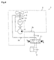
- Fig. 4 is hydraulic equipment 1 adopting one embodiment of a hydraulic pump unit (fluid pressure pump unit), according to the present invention.
- Fig. 4 is a diagram illustrating a hydraulic circuit.
- the hydraulic equipment 1 of the present embodiment includes: a double-acting hydraulic cylinder 2 serving as a hydraulic actuator; and a hydraulic pump unit 3 for supplying pressure oil to the hydraulic cylinder 2.
- the hydraulic pump unit 3 essentially has: a hydraulic pump 4 (fluid pressure pump) which pressurizes a hydraulic oil (hydraulic fluid); a motor 5 which has an output shaft 5a and drives the hydraulic pump 4; a cooling fan 7 which is connected to the output shaft 5a of the motor 5 and generates a flow of cooling air 6 schematically illustrated by an alternate long and short dash line to cool the motor 5; and a radiator 8 for receiving heat from the hydraulic oil (hydraulic fluid).
- Indicated by reference numbers 10 and 11 are respectively a pump check valve and a three-position four-port directional valve. These pump check valve 10 and three-position four-port directional valve 11 are for controlling the operation of the hydraulic cylinder 2.
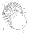
- Fig. 1 is a broken-away fragmentary perspective view illustrating the one embodiment of a hydraulic pump unit according to the present invention.
- Fig. 2 is a cross sectional view taken along the line 2-2 of Fig. 1 .
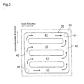
- Fig. 3 is a partial exploded view of an inside housing.
- a housing 32 of the motor 5 is constituted by an inside housing 12 (first housing), and an outside housing 13 (second housing) fitted at the outside of the inside housing 12. Fitting gaps between the inside housing 12 and the outside housing 13 are sealed by a schematically illustrated oil seal 14. On the inner circumferential surface of the inside housing 12 is arranged a stator 15 having an electromagnet (coil).
- the cooling fan 7, the radiator 8, motor 5, and hydraulic pump 4 are sequentially aligned in this order in the axial direction of the output shaft 5a of the motor 5. That is, the radiator 8 is disposed between the cooling fan 7 and the motor 5, and the hydraulic pump 4 is disposed at the opposite side of the radiator 8 across the motor 5.
- the hydraulic pump 4 and the radiator 8 are coaxially fixed by means of not-illustrated screw to the motor 5 so as to interpose therebetween the motor 5.
- the output shaft 5a of the motor 5 is supported by a bearing 16 provided to a flange 12a of the inside housing 12 and a bearing 17 provided to the radiator 8.
- a schematically depicted permanent magnet 18, and this permanent magnet 18 and the output shaft 5a form a rotor 19 of the motor 5.
- a base end 21 of the output shaft 5a is connected to a driving unit inside the hydraulic pump 4.
- rotation of the rotor 19 of the motor 5 causes ejection of pressure oil from the hydraulic pump 4 to the directional valve 11 of Fig. 4 , rotates the cooling fan 7 of Fig. 2 in a predetermined direction, and generates the flow of cooling air 6 parallel to the axial direction of the output shaft 5a.
- the radiator 8 is located on the windward of the motor 5.
- each first radiation fin 22 has a predetermined height outwardly in a radial direction from an outer circumferential surface 13a of the outside housing 13 constituting the housing 32 of the motor 5, and extends along the direction of the axis C.
- the first radiation fins 22 are arranged at a predetermined interval in the circumferential direction.
- each second radiation fin 23 has a predetermined height outwardly in a radial direction from an outer circumferential surface 8a of the radiator 8, and extends along the direction of the axis C.
- the second radiation fins 23 are arranged at a predetermined interval in the circumferential direction.
- the predetermined heights of the first radiation fins 22 and the second radiation fins 23 are the same, and the thicknesses of these fins are also the same.
- the motor 5 and radiator 8 are circumferentially positioned around the axis C so that each first radiation fin 22 and each second radiation fin 23 are aligned along the flow of cooling air 6, in other words, unevenness between each first radiation fin 22 and each second radiation fin 23 is prevented, that is, each first radiation fin 22 and each second radiation fin 23 smoothly connect with each other.
- the hydraulic pump unit 3 further has a unit cover 24 which covers the periphery of the first and second radiation fins 22 and 23.
- This unit cover 24 has a cylindrical part 25 which covers the periphery of the first and second radiation fins 22 and 23 in such a manner that the cylindrical part 25 abuts the outer edges 22a of the first radiation fins 22 and the outer edges 23a of the second radiation fins 23; and a protection cover 26 provided mainly for the safety purpose. On the protection cover 26 are formed a number of slits as illustrated.
- a quadrangular prism-shaped passage 44 for the flow of cooling air 6 generated by the rotation of the cooling fan 7 is formed by: two first radiation fins 22 circumferentially adjacent to each other; two second radiation fins 23 circumferentially adjacent to each other; the outer circumferential surface 13a of the outside housing 13; the outer circumferential surface 8a of the radiator 8; and the cylindrical part 25.
- the motor 5 and radiator 8 are disposed coaxially with the cooling fan 7 so that the motor 5 and the radiator 8 are overlapped with the cooling fan 7, when viewed from the axial direction of the output shaft 5a of the motor 5. That is, concentric circles are conceivable when viewing the cooling fan 7, the radiator 8, and the motor 5 from the axial direction of the output shaft 5a of the motor 5 (see also Fig. 1 ).
- the hydraulic oil ejected from the hydraulic cylinder 2 (see also Fig. 4 ) is fed into a first inlet/outlet port 3a of the hydraulic pump unit 3 through the directional valve 11, and then fed into a cooling passage 29 inside the radiator 8, sequentially through a passage 27 in the hydraulic pump 4 and a communication passage 28 formed in the motor 5.
- the hydraulic oil having been cooled in the cooling passage 29 is then fed into a passage 31 in the hydraulic pump 4 through a communication passage 30 formed in the motor 5, after which the hydraulic oil is ejected from a second inlet/outlet port 3b of the hydraulic pump unit 3 and supplied to the hydraulic cylinder 2 through the pump check valve 10 and the directional valve 11.
- the passages 27 and 31 in the hydraulic pump 4 and the cooling passage 29 in the radiator 8 are in communication with one another through the communication passages 28 and 30 formed in the motor 5.
- These communication passages 28 and 30 are formed inside the housing 32 of the motor 5.
- the housing 32 of the motor 5 has the inside housing 12 and the outside housing 13 as is mentioned hereinabove, and the communication passage 28 includes a first passage 33, a second passage 37, and a third passage 38.
- the first passage 33 is formed in the outside housing 13 by boring, and communicates with the passage 27 in the hydraulic pump 4.
- the second passage 37 is formed by a groove 35 carved on the outer circumferential surface 34 of the inside housing 12 and the inner circumferential surface 36 of the outside housing 13, and communicates with the first passage 33.
- the third passage 38 is formed in the outside housing 13 by boring, and connects the second passage 37 with the cooling passage 29 in the radiator 8.
- the communication passage 30 is structured in substantially the same manner as the communication passage 28.
- FIG. 3 is a partial exploded view of the outer circumferential surface 34 of the inside housing 12.
- the circumferential direction of the inside housing 12 correspond to the up/down direction in the figure. This figure only presents a half of the exploded outer circumferential surface 34, and the straight long dashed double-short dashed line in the figure represents the boundary with the other half of the exploded outer circumferential surface 34 whose illustration has been omitted.
- the groove 35 includes a circumferential groove 40, a circumferential groove 42, and a plurality of communication grooves 43.
- the circumferential groove 40 extends in the circumferential direction from a junction 39 at which the groove 35 and the first passage 33 are connected to one other.
- the circumferential groove 42 extends in the circumferential direction from a junction 41 at which the groove 35 and the third passage 38 are connected to one other.
- the communication grooves 43 extend in the axial direction of the output shaft of the motor, and connect the circumferential grooves 40 and 42 extending parallel to each other at predetermined intervals in the circumferential direction, thus discretely.
- the groove 35 is formed in substantially a ladder-like shape.
- each groove 35 does not straightly communicate the junctions 39 and 41, it is possible to express that the communication passage 28 shown in Fig. 2 is formed so as to make a detour in the housing 32 of the motor 5.
- the hydraulic oil fed into the groove 35 through the junction 39 is fed into each communication groove 43 directly or indirectly via the circumferential groove 40, and fed from the communication groove 43 into the junction 41 directly or indirectly through the circumferential groove 42.
- each groove 35 has such a large area to cover the inside housing 12 as illustrated in Fig. 1 . That is, for example, each groove 35 is formed so as to cover 1/4 to 1/2 of the circumferential surface of the inside housing 12.
- the hydraulic oil discharged from the hydraulic cylinder 2 of Fig. 4 during operation of the hydraulic cylinder 2 is heated by frictional heat or the like at the time of passing the directional valve 11 shown in Fig. 2 .
- the high temperature hydraulic oil is supplied to the communication passage 28 formed in the motor 5, through the passage 27 in the hydraulic pump 4.
- the heat of the hydraulic oil is absorbed by the housing 32 of the motor 5 and the hydraulic oil is cooled.
- the hydraulic oil slightly cooled in the communication passage 28 is fed into the cooling passage 29 in the radiator 8, and strongly cooled by transferring heat to the air-cooled radiator 8.
- the hydraulic oil having been cooled down in the cooling passage 29 is fed into the communication passage 30 formed in the motor 5.
- the hydraulic oil passes the communication passage 30, the heat of the hydraulic oil is absorbed by the housing 32 of the motor 5 and the hydraulic oil is further cooled. After passing the communication passage 30, the hydraulic oil gains energy at the hydraulic pump 4, and is eventually supplied to the hydraulic cylinder 2. Thus, an excessive increase in the temperature of the hydraulic oil is prevented.
- the temperature of the hydraulic oil is targeted at about 110 deg C, from various technical view point. Further, a result of a known calculation shows that the temperature of the hydraulic oil, at the ambient temperature of 70 deg C, rises approximately up to 170 deg C, if the above cooling is not at all conducted. Note that, the above mentioned constant flow of cooling air 6 generated by rotation of the cooling fan 7 in the passage 44 during the series of the above operation constantly cools the housing 32 of the motor 5 and the radiator 8.
- the hydraulic pump unit 3 (fluid pressure pump unit) of the above embodiment is structured as follows.
- the hydraulic pump unit 3 includes: the hydraulic pump 4 (fluid pressure pump) which pressurizes the hydraulic oil(hydraulic fluid); the motor 5 (motor) which has the output shaft 5a and drives the hydraulic pump 4; the cooling fan 7 which is connected to the output shaft 5a of the motor 5 and generates the flow of cooling air 6 to cool the motor 5; and the radiator 8 which receives heat from the hydraulic oil.
- the motor 5 and the radiator 8 are overlapped with the cooling fan 7, when viewed from the axial direction of the output shaft 5a of the motor 5.
- the flow of cooling air 6 is utilized not only for cooling the motor 5 but also for cooling the radiator 8, thereby contributing to downsizing of the hydraulic equipment 1. If sufficient cooling effect is achievable with the above structure, there will be no need of providing another cooling device (out-mountable radiator or the like) separately from the hydraulic pump unit 3. This contributes to weight reduction of the hydraulic equipment 1 and simplifies pipe laying in the equipment, thus improving the maintenance characteristics.
- the above embodiment deals with hydraulic equipment as an example of a fluid pressure equipment, and uses the expression such as "hydraulic pump unit” and “hydraulic oil” frequently in the explanation in concert with the example; however, the application of the present invention is not limited to hydraulic equipment.
- a motor using an electromagnetic force is mentioned as an example of the motor.
- the motor however may be an engine utilizing expansional action of combustion.
- the cooling fan 7, radiator 8, and motor 5 are straightly aligned as shown in Figs.
- the thought of the present invention is fully utilized as long as the motor 5 and the radiator 8 are overlapped, even by little, with the cooling fan 7, when viewed from the axial direction of the output shaft 5a of the motor 5.
- the radiator 8 may be disposed between the hydraulic pump 4 and the motor 5, or disposed at the opposite side of the motor 5 across the cooling fan 7.
- the hydraulic pump unit 3 is further structured as follows. Namely, the radiator 8 is disposed between the cooling fan 7 and the motor 5. This structure, which gives more priority to cooling of the radiator 8 over cooling of the motor 5, excels in cooling the hydraulic oil. Because, when giving eye to the flow of cooling air 6 generated by the cooling fan 7, the radiator 8 is located the windward of the motor 5.
- the hydraulic pump unit 3 is further structured as follows. Namely, the hydraulic pump 4 is disposed at the opposite side of the radiator 8 across the motor 5. The passages 27 and 31 in the hydraulic pump 4 and the cooling passage 29 (passage) in the radiator 8 are in communication with one another through the communication passages 28 and 30 formed in the motor 5. In the above structure, a special plumbing communicating the passages 27 and 31 in the hydraulic pump 4 with the cooling passage 29 in the radiator 8 is formed in the motor 5. This structure contributes to weight reduction and improvement of maintenance characteristic, compared to a case of providing the plumbing outside the motor 5.
- the hydraulic pump unit 3 is further structured as follows. Namely, the communication passages 28 and 30 are formed in the housing 32 of the motor 5. Although the communication passages 28 and 30 are formed inside the motor 5, the basic operation of the motor 5 is not affected. Further with the structure, heat is transferred from the hydraulic oil flowing in the communication passages 28 and 30 to the housing 32 of the motor 5, thereby contributing to cooling of the hydraulic oil.
- the hydraulic pump unit 3 is further structured as follows. Namely, the housing 32 of the motor 5 includes the inside housing 12 (first housing) and the outside housing 13 (second housing) fitted at the outside of the inside housing 12.
- the second passage 37 which is a part of the communication passage 28 (or communication passage 30) includes the groove 35 as its constituting element, the groove 35 being formed on the outer circumferential surface 34 of the inside housing 12. This structure allows easier formation of the communication passage 28 (communication passage 30).
- the second passage 37 which is a part of the communication passage 28 may include a groove carved on the inner circumferential surface 36 of the outside housing 13, or include both this groove and the above mentioned groove 35.
- the second passage 37 is formed, for example, by that groove and the outer circumferential surface 34 of the inside housing 12.
- the second passage 37 may be structured by a combination of that groove and the above mentioned groove 35 which face with each other.
- the entire communication passage 28 has, as its constituting element, a groove carved on at least one of the outer circumferential surface 34 of the inside housing 12 and the inner circumferential surface 36 of the outside housing 13.
- the hydraulic pump unit 3 is further structured as follows. Namely, the communication passages 28 and 30 are formed so as to make a detour inside the housing 32 of the motor 5. The structure ensures a large contact area between the hydraulic oil flowing in the communication passages 28 and 30 and the housing 32 of the motor 5, thereby enhancing heat transfer from the hydraulic oil to the housing 32.
- the communication passage 28 shown in Fig. 3 is formed so as to largely make a detour at the second passage 37 formed in a ladder-like shape.
- the communication passage 28 may be formed as a passage smoothly meandering like a sine wave, or as a passage meandering in a step-like manner like a square wave.
- the hydraulic pump unit 3 is further structured as follows. Namely, the first radiation fin 22 extending in the axial direction of the output shaft 5a is formed on the outer circumference of the motor 5. The second radiation fin 23 extending in the axial direction of the output shaft 5a is formed on the outer circumference of the radiator 8. The first and second radiation fins 22 and 23 are aligned along the flow of cooling air 6. This structure restrains the resistance against the flow of cooling air 6 at the boundary between the first and second radiation fins 22 and 23. Therefore, the flow of cooling air 6 easily reaches the both first and second radiation fins 22 and 23, even if the flow of cooling air 6 is used for cooling both the motor 5 and the radiator 8.
- the hydraulic pump unit 3 is further structured as follows. Namely, the unit cover 24 covering the periphery of the first and second radiation fins 22 and 23 is provided. With the structure, the first and second radiation fins 22 and 23 and the unit cover 24 form the passage 44 for the flow of cooling air 6, thereby preventing dispersion of the flow of cooling air 6. Therefore, the flow of cooling air 6 more easily reaches the both first and second radiation fins 22 and 23, even if the flow of cooling air 6 is used for cooling both the motor 5 and the radiator 8.
- the communication passages 28 and 30 for the flow of the hydraulic oil are formed inside the housing 32 of the motor 5. This structure allows heat transfer from the hydraulic oil to the housing 32 of the motor 5, thus contributing to cooling of the hydraulic oil.
- the hydraulic equipment 1 of the above embodiment includes a double-acting hydraulic cylinder 2.
- the hydraulic equipment 1 may adopt a single-acting hydraulic cylinder in place of the double-acting hydraulic cylinder 2.
Landscapes
- Engineering & Computer Science (AREA)
- Mechanical Engineering (AREA)
- General Engineering & Computer Science (AREA)
- Details Of Reciprocating Pumps (AREA)
- Cooling, Air Intake And Gas Exhaust, And Fuel Tank Arrangements In Propulsion Units (AREA)
Abstract
Description
- The present invention relates to a fluid pressure pump unit.
- Patent document 1 (
JP10-68142A - Fluid pressure equipment in general has a radiator for cooling hydraulic fluid, the radiator being disposed in a position apart from a fluid pressure pump. A cooling fan for cooling the radiator is additionally installed. Today, downsizing of the fluid pressure equipment is required for the purpose of improving the maintenance characteristic of the fluid pressure equipment itself or peripherals thereof.
- The present invention is made in view of the problems, and is mainly intended to provide a technology for downsizing fluid pressure equipment including a fluid pressure pump and a radiator.
- The technical problem to be solved by the present invention is as described above, and means to solve the problem and its effect is described hereinbelow.
- The first aspect of the present invention provides a fluid pressure pump unit structured as follows. Namely, the fluid pressure pump unit includes: a fluid pressure pump which pressurizes a hydraulic fluid; a motor which has an output shaft and drives the fluid pressure pump; a cooling fan which is connected to the output shaft of the motor and generates a flow of cooling air to cool the motor; and a radiator which receives heat from the hydraulic fluid. The motor and the radiator are overlapped at least partially with the cooling fan, when viewed from an axial direction of the output shaft of the motor. In this structure, the flow of cooling air is utilized not only for cooling the motor but also for cooling the radiator, thereby contributing to downsizing of the fluid pressure equipment.
- Note that "radiator" in Patent document 1 is a member for cooling an engine. On the other hand, the "radiator" in the present invention is a member for cooling the hydraulic fluid, rather than a member for cooling the motor (corresponding to the engine). That is, the technical significance of "radiator" which is an essential element of the present invention is very different.
- Further, the fluid pressure pump unit is structured as follows. Namely, the radiator is disposed between the cooling fan and the motor. This structure, which gives more priority to cooling of the radiator over cooling of the motor, excels in cooling the hydraulic fluid.
- Further, the fluid pressure pump unit is structured as follows. Namely, the fluid pressure pump is disposed at the opposite side of the radiator across the motor. A passage in the fluid pressure pump and a passage in the radiator are in communication with each other through a communication passage formed in the motor. In the above structure, a special plumbing communicating the passage in the fluid pressure pump with the passage in the radiator is formed in the motor. This structure contributes to weight reduction and improvement of maintenance characteristic, compared to a case of providing the plumbing outside the motor.
- Further, the fluid pressure pump unit is structured as follows. Namely, the communication passage is formed in a housing of the motor. Although the communication passage is formed inside the motor, the basic operation of the motor is not affected. Further with the structure, heat is transferred from the hydraulic fluid flowing in the communication passage to the housing of the motor, thereby contributing to cooling of the hydraulic fluid.
- Further, the fluid pressure pump unit is structured as follows. Namely, the housing of the motor includes a first housing and a second housing fitted at the outside of the first housing. At least a part of the communication passage includes a groove as its constituting element, the groove being formed on one of an outer circumferential surface of the first housing and an inner circumferential surface of the second housing. This structure allows easier formation of the communication passage.
- Further, the fluid pressure pump unit is structured as follows. Namely, the communication passage is formed so as to make a detour inside the housing of the motor. This structure ensures a large contact area between the hydraulic fluid flowing in the communication passage and the housing of the motor, thereby enhancing heat transfer from the hydraulic fluid to the housing.
- Further, the fluid pressure pump unit is structured as follows. Namely, a first radiation fin extending in the axial direction of the output shaft is formed on the outer circumference of the motor. A second radiation fin extending in the axial direction of the output shaft is formed on the outer circumference of the radiator. The first and second radiation fins are aligned along the flow of cooling air. This structure restrains the resistance against the flow of cooling air at the boundary between the first and second radiation fins. Therefore, the flow of cooling air easily reaches the both first and second radiation fins, even if the flow of cooling air is used for cooling both the motor and the radiator.
- Further, the fluid pressure pump unit is structured as follows. Namely, a unit cover covering the periphery of the first and second radiation fins is provided. With the structure, the first and second radiation fins and the unit cover form a passage for the flow of cooling air, thereby preventing dispersion of the flow of cooling air. Therefore, the flow of cooling air more easily reaches the both first and second radiation fins, even if the flow of cooling air is used for cooling both the motor and the radiator.
- The second aspect of the present invention provides a fluid pressure pump unit structured as follows. Namely, the fluid pressure pump unit includes: a fluid pressure pump which pressurizes a hydraulic fluid; a motor which has an output shaft and drives the fluid pressure pump; and a cooling fan which is connected to the output shaft of the motor and generates a flow of cooling air to cool the motor. A passage for a flow of the hydraulic fluid is formed in a housing of the motor. This structure allows heat transfer from the hydraulic fluid to the housing of the motor, thus contributing to cooling of the hydraulic fluid.
-
-
Fig. 1 is a broken-away fragmentary perspective view illustrating an embodiment of a hydraulic pump unit, according to the present invention. -
Fig. 2 is a cross sectional view taken along the line 2-2 ofFig. 1 . -
Fig. 3 is a partially exploded view of the inside housing. -
Fig. 4 is a diagram of a hydraulic circuit. -
- 1 Hydraulic Equipment
- 2 Hydraulic Cylinder
- 3 Hydraulic Pump Unit
- 4 Hydraulic Pump
- 5 Motor
- 5a Output Shaft of Motor
- 6 Flow of Cooling Air
- 7 Cooling Fan
- 8 Radiator
- The following describes an embodiment of the present invention with reference to attached drawings.
- First described with reference to
Fig. 4 is hydraulic equipment 1 adopting one embodiment of a hydraulic pump unit (fluid pressure pump unit), according to the present invention.Fig. 4 is a diagram illustrating a hydraulic circuit. - As illustrated in this figure, the hydraulic equipment 1 of the present embodiment includes: a double-acting
hydraulic cylinder 2 serving as a hydraulic actuator; and ahydraulic pump unit 3 for supplying pressure oil to thehydraulic cylinder 2. - The
hydraulic pump unit 3 essentially has: a hydraulic pump 4 (fluid pressure pump) which pressurizes a hydraulic oil (hydraulic fluid); amotor 5 which has anoutput shaft 5a and drives thehydraulic pump 4; a coolingfan 7 which is connected to theoutput shaft 5a of themotor 5 and generates a flow of coolingair 6 schematically illustrated by an alternate long and short dash line to cool themotor 5; and aradiator 8 for receiving heat from the hydraulic oil (hydraulic fluid). Indicated byreference numbers pump check valve 10 and three-position four-portdirectional valve 11 are for controlling the operation of thehydraulic cylinder 2. - Next, the structure of the
hydraulic pump unit 3 is further detailed with reference toFigs. 1 to 3 .Fig. 1 is a broken-away fragmentary perspective view illustrating the one embodiment of a hydraulic pump unit according to the present invention.Fig. 2 is a cross sectional view taken along the line 2-2 ofFig. 1 .Fig. 3 is a partial exploded view of an inside housing. - See
Fig. 2 first. As illustrated in this figure, ahousing 32 of themotor 5 is constituted by an inside housing 12 (first housing), and an outside housing 13 (second housing) fitted at the outside of theinside housing 12. Fitting gaps between theinside housing 12 and theoutside housing 13 are sealed by a schematically illustratedoil seal 14. On the inner circumferential surface of theinside housing 12 is arranged astator 15 having an electromagnet (coil). - The cooling
fan 7, theradiator 8,motor 5, andhydraulic pump 4 are sequentially aligned in this order in the axial direction of theoutput shaft 5a of themotor 5. That is, theradiator 8 is disposed between the coolingfan 7 and themotor 5, and thehydraulic pump 4 is disposed at the opposite side of theradiator 8 across themotor 5. - The
hydraulic pump 4 and theradiator 8 are coaxially fixed by means of not-illustrated screw to themotor 5 so as to interpose therebetween themotor 5. Theoutput shaft 5a of themotor 5 is supported by abearing 16 provided to aflange 12a of theinside housing 12 and abearing 17 provided to theradiator 8. On the outer circumference of theoutput shaft 5a is attached a schematically depictedpermanent magnet 18, and thispermanent magnet 18 and theoutput shaft 5a form a rotor 19 of themotor 5. - Where an end of the
output shaft 5a to which the coolingfan 7 is provided is aleading end 20, abase end 21 of theoutput shaft 5a is connected to a driving unit inside thehydraulic pump 4. - In this structure, rotation of the rotor 19 of the
motor 5 causes ejection of pressure oil from thehydraulic pump 4 to thedirectional valve 11 ofFig. 4 , rotates the coolingfan 7 ofFig. 2 in a predetermined direction, and generates the flow of coolingair 6 parallel to the axial direction of theoutput shaft 5a. When giving an eye to this flow of coolingair 6, theradiator 8 is located on the windward of themotor 5. - See
Fig. 1 for the following. For the sake of convenience, the axis of the not-illustrated output shaft of themotor 5 is given the reference symbol C in the figure. As illustrated,first radiation fins 22 each extending in the direction of the axis C are formed on an outer circumference of themotor 5, andsecond radiation fins 23 each extending in the direction of the axis C are formed on an outer circumference of theradiator 8. This is more specifically described below. Namely, eachfirst radiation fin 22 has a predetermined height outwardly in a radial direction from an outercircumferential surface 13a of theoutside housing 13 constituting thehousing 32 of themotor 5, and extends along the direction of the axis C. Thefirst radiation fins 22 are arranged at a predetermined interval in the circumferential direction. Similarly, eachsecond radiation fin 23 has a predetermined height outwardly in a radial direction from an outercircumferential surface 8a of theradiator 8, and extends along the direction of the axis C. Thesecond radiation fins 23 are arranged at a predetermined interval in the circumferential direction. The predetermined heights of thefirst radiation fins 22 and thesecond radiation fins 23 are the same, and the thicknesses of these fins are also the same. Further, themotor 5 andradiator 8 are circumferentially positioned around the axis C so that eachfirst radiation fin 22 and eachsecond radiation fin 23 are aligned along the flow of coolingair 6, in other words, unevenness between eachfirst radiation fin 22 and eachsecond radiation fin 23 is prevented, that is, eachfirst radiation fin 22 and eachsecond radiation fin 23 smoothly connect with each other. - The
hydraulic pump unit 3 further has aunit cover 24 which covers the periphery of the first andsecond radiation fins cylindrical part 25 which covers the periphery of the first andsecond radiation fins cylindrical part 25 abuts theouter edges 22a of thefirst radiation fins 22 and theouter edges 23a of thesecond radiation fins 23; and aprotection cover 26 provided mainly for the safety purpose. On theprotection cover 26 are formed a number of slits as illustrated. In this structure, a quadrangular prism-shapedpassage 44 for the flow of coolingair 6 generated by the rotation of the coolingfan 7 is formed by: twofirst radiation fins 22 circumferentially adjacent to each other; twosecond radiation fins 23 circumferentially adjacent to each other; the outercircumferential surface 13a of theoutside housing 13; the outercircumferential surface 8a of theradiator 8; and thecylindrical part 25. - Further, as illustrated in
Fig. 2 , themotor 5 andradiator 8 are disposed coaxially with the coolingfan 7 so that themotor 5 and theradiator 8 are overlapped with the coolingfan 7, when viewed from the axial direction of theoutput shaft 5a of themotor 5. That is, concentric circles are conceivable when viewing the coolingfan 7, theradiator 8, and themotor 5 from the axial direction of theoutput shaft 5a of the motor 5 (see alsoFig. 1 ). - Next, the following details the passage of the hydraulic oil inside the
hydraulic pump unit 3. - See
Fig. 2 for the following. As illustrated in this figure, the hydraulic oil ejected from the hydraulic cylinder 2 (see alsoFig. 4 ) is fed into a first inlet/outlet port 3a of thehydraulic pump unit 3 through thedirectional valve 11, and then fed into acooling passage 29 inside theradiator 8, sequentially through apassage 27 in thehydraulic pump 4 and acommunication passage 28 formed in themotor 5. The hydraulic oil having been cooled in thecooling passage 29 is then fed into apassage 31 in thehydraulic pump 4 through acommunication passage 30 formed in themotor 5, after which the hydraulic oil is ejected from a second inlet/outlet port 3b of thehydraulic pump unit 3 and supplied to thehydraulic cylinder 2 through thepump check valve 10 and thedirectional valve 11. - As described, the
passages hydraulic pump 4 and thecooling passage 29 in theradiator 8 are in communication with one another through thecommunication passages motor 5. Thesecommunication passages housing 32 of themotor 5. Specifically, thehousing 32 of themotor 5 has theinside housing 12 and theoutside housing 13 as is mentioned hereinabove, and thecommunication passage 28 includes afirst passage 33, asecond passage 37, and athird passage 38. Thefirst passage 33 is formed in theoutside housing 13 by boring, and communicates with thepassage 27 in thehydraulic pump 4. Thesecond passage 37 is formed by agroove 35 carved on the outercircumferential surface 34 of theinside housing 12 and the innercircumferential surface 36 of theoutside housing 13, and communicates with thefirst passage 33. Thethird passage 38 is formed in theoutside housing 13 by boring, and connects thesecond passage 37 with thecooling passage 29 in theradiator 8. Thecommunication passage 30 is structured in substantially the same manner as thecommunication passage 28. - Next, the following details with reference to
Fig. 3 thegroove 35 which is carved on the outercircumferential surface 34 of theinside housing 12, and is a constituting element of thesecond passage 37 forming a part of thecommunication passage 28.Fig. 3 is a partial exploded view of the outercircumferential surface 34 of theinside housing 12. The circumferential direction of theinside housing 12 correspond to the up/down direction in the figure. This figure only presents a half of the exploded outercircumferential surface 34, and the straight long dashed double-short dashed line in the figure represents the boundary with the other half of the exploded outercircumferential surface 34 whose illustration has been omitted. - As illustrated in the figure, the
groove 35 includes acircumferential groove 40, acircumferential groove 42, and a plurality ofcommunication grooves 43. Thecircumferential groove 40 extends in the circumferential direction from ajunction 39 at which thegroove 35 and thefirst passage 33 are connected to one other. Thecircumferential groove 42 extends in the circumferential direction from ajunction 41 at which thegroove 35 and thethird passage 38 are connected to one other. Thecommunication grooves 43 extend in the axial direction of the output shaft of the motor, and connect thecircumferential grooves groove 35 is formed in substantially a ladder-like shape. Further, considering that thegroove 35 does not straightly communicate thejunctions communication passage 28 shown inFig. 2 is formed so as to make a detour in thehousing 32 of themotor 5. With the above structure, the hydraulic oil fed into thegroove 35 through thejunction 39 is fed into eachcommunication groove 43 directly or indirectly via thecircumferential groove 40, and fed from thecommunication groove 43 into thejunction 41 directly or indirectly through thecircumferential groove 42. Note that eachgroove 35 has such a large area to cover theinside housing 12 as illustrated inFig. 1 . That is, for example, eachgroove 35 is formed so as to cover 1/4 to 1/2 of the circumferential surface of theinside housing 12. - Next, the following describes the operation of the present embodiment. The flow of the hydraulic oil has been already described herein above. The following therefore mainly describes heat transfer.
- See
Figs. 4 and2 for the following. The hydraulic oil discharged from thehydraulic cylinder 2 ofFig. 4 during operation of thehydraulic cylinder 2 is heated by frictional heat or the like at the time of passing thedirectional valve 11 shown inFig. 2 . The high temperature hydraulic oil is supplied to thecommunication passage 28 formed in themotor 5, through thepassage 27 in thehydraulic pump 4. When the high temperature hydraulic oil passes thecommunication passage 28, the heat of the hydraulic oil is absorbed by thehousing 32 of themotor 5 and the hydraulic oil is cooled. Next, the hydraulic oil slightly cooled in thecommunication passage 28 is fed into thecooling passage 29 in theradiator 8, and strongly cooled by transferring heat to the air-cooledradiator 8. Next, the hydraulic oil having been cooled down in thecooling passage 29 is fed into thecommunication passage 30 formed in themotor 5. When the hydraulic oil passes thecommunication passage 30, the heat of the hydraulic oil is absorbed by thehousing 32 of themotor 5 and the hydraulic oil is further cooled. After passing thecommunication passage 30, the hydraulic oil gains energy at thehydraulic pump 4, and is eventually supplied to thehydraulic cylinder 2. Thus, an excessive increase in the temperature of the hydraulic oil is prevented. Note that the temperature of the hydraulic oil is targeted at about 110 deg C, from various technical view point. Further, a result of a known calculation shows that the temperature of the hydraulic oil, at the ambient temperature of 70 deg C, rises approximately up to 170 deg C, if the above cooling is not at all conducted. Note that, the above mentioned constant flow of coolingair 6 generated by rotation of the coolingfan 7 in thepassage 44 during the series of the above operation constantly cools thehousing 32 of themotor 5 and theradiator 8. - As hereinabove mentioned, the hydraulic pump unit 3 (fluid pressure pump unit) of the above embodiment is structured as follows. Namely, the
hydraulic pump unit 3 includes: the hydraulic pump 4 (fluid pressure pump) which pressurizes the hydraulic oil(hydraulic fluid); the motor 5 (motor) which has theoutput shaft 5a and drives thehydraulic pump 4; the coolingfan 7 which is connected to theoutput shaft 5a of themotor 5 and generates the flow of coolingair 6 to cool themotor 5; and theradiator 8 which receives heat from the hydraulic oil. Themotor 5 and theradiator 8 are overlapped with the coolingfan 7, when viewed from the axial direction of theoutput shaft 5a of themotor 5. In this structure, the flow of coolingair 6 is utilized not only for cooling themotor 5 but also for cooling theradiator 8, thereby contributing to downsizing of the hydraulic equipment 1. If sufficient cooling effect is achievable with the above structure, there will be no need of providing another cooling device (out-mountable radiator or the like) separately from thehydraulic pump unit 3. This contributes to weight reduction of the hydraulic equipment 1 and simplifies pipe laying in the equipment, thus improving the maintenance characteristics. - Note that the above embodiment deals with hydraulic equipment as an example of a fluid pressure equipment, and uses the expression such as "hydraulic pump unit" and "hydraulic oil" frequently in the explanation in concert with the example; however, the application of the present invention is not limited to hydraulic equipment. Further, in the above embodiment, a motor using an electromagnetic force is mentioned as an example of the motor. The motor however may be an engine utilizing expansional action of combustion. Further, in the above embodiment, the cooling
fan 7,radiator 8, andmotor 5 are straightly aligned as shown inFigs. 1 ,2 , and4 ; however, the thought of the present invention is fully utilized as long as themotor 5 and theradiator 8 are overlapped, even by little, with the coolingfan 7, when viewed from the axial direction of theoutput shaft 5a of themotor 5. Further, instead of disposing theradiator 8 between themotor 5 and the coolingfan 7, theradiator 8 may be disposed between thehydraulic pump 4 and themotor 5, or disposed at the opposite side of themotor 5 across the coolingfan 7. - The
hydraulic pump unit 3 is further structured as follows. Namely, theradiator 8 is disposed between the coolingfan 7 and themotor 5. This structure, which gives more priority to cooling of theradiator 8 over cooling of themotor 5, excels in cooling the hydraulic oil. Because, when giving eye to the flow of coolingair 6 generated by the coolingfan 7, theradiator 8 is located the windward of themotor 5. - The
hydraulic pump unit 3 is further structured as follows. Namely, thehydraulic pump 4 is disposed at the opposite side of theradiator 8 across themotor 5. Thepassages hydraulic pump 4 and the cooling passage 29 (passage) in theradiator 8 are in communication with one another through thecommunication passages motor 5. In the above structure, a special plumbing communicating thepassages hydraulic pump 4 with thecooling passage 29 in theradiator 8 is formed in themotor 5. This structure contributes to weight reduction and improvement of maintenance characteristic, compared to a case of providing the plumbing outside themotor 5. - The
hydraulic pump unit 3 is further structured as follows. Namely, thecommunication passages housing 32 of themotor 5. Although thecommunication passages motor 5, the basic operation of themotor 5 is not affected. Further with the structure, heat is transferred from the hydraulic oil flowing in thecommunication passages housing 32 of themotor 5, thereby contributing to cooling of the hydraulic oil. - The
hydraulic pump unit 3 is further structured as follows. Namely, thehousing 32 of themotor 5 includes the inside housing 12 (first housing) and the outside housing 13 (second housing) fitted at the outside of theinside housing 12. Thesecond passage 37 which is a part of the communication passage 28 (or communication passage 30) includes thegroove 35 as its constituting element, thegroove 35 being formed on the outercircumferential surface 34 of theinside housing 12. This structure allows easier formation of the communication passage 28 (communication passage 30). - Instead of the above structure, the
second passage 37 which is a part of thecommunication passage 28 may include a groove carved on the innercircumferential surface 36 of theoutside housing 13, or include both this groove and the above mentionedgroove 35. In the former case, that is, a case of including the groove formed on the innercircumferential surface 36, thesecond passage 37 is formed, for example, by that groove and the outercircumferential surface 34 of theinside housing 12. In the latter case, thesecond passage 37 may be structured by a combination of that groove and the above mentionedgroove 35 which face with each other. - Further, in the embodiment, only the
second passage 37 which is a part of thecommunication passage 28 has thegroove 35 as its constituting element, and the other parts, namely the first andthird passages entire communication passage 28 has, as its constituting element, a groove carved on at least one of the outercircumferential surface 34 of theinside housing 12 and the innercircumferential surface 36 of theoutside housing 13. - The
hydraulic pump unit 3 is further structured as follows. Namely, thecommunication passages housing 32 of themotor 5. The structure ensures a large contact area between the hydraulic oil flowing in thecommunication passages housing 32 of themotor 5, thereby enhancing heat transfer from the hydraulic oil to thehousing 32. - Note that, in the above embodiment, the
communication passage 28 shown inFig. 3 is formed so as to largely make a detour at thesecond passage 37 formed in a ladder-like shape. Instead however, thecommunication passage 28 may be formed as a passage smoothly meandering like a sine wave, or as a passage meandering in a step-like manner like a square wave. - The
hydraulic pump unit 3 is further structured as follows. Namely, thefirst radiation fin 22 extending in the axial direction of theoutput shaft 5a is formed on the outer circumference of themotor 5. Thesecond radiation fin 23 extending in the axial direction of theoutput shaft 5a is formed on the outer circumference of theradiator 8. The first andsecond radiation fins air 6. This structure restrains the resistance against the flow of coolingair 6 at the boundary between the first andsecond radiation fins air 6 easily reaches the both first andsecond radiation fins air 6 is used for cooling both themotor 5 and theradiator 8. - The
hydraulic pump unit 3 is further structured as follows. Namely, theunit cover 24 covering the periphery of the first andsecond radiation fins second radiation fins unit cover 24 form thepassage 44 for the flow of coolingair 6, thereby preventing dispersion of the flow of coolingair 6. Therefore, the flow of coolingair 6 more easily reaches the both first andsecond radiation fins air 6 is used for cooling both themotor 5 and theradiator 8. - Further, as illustrated in
Fig. 2 , thecommunication passages housing 32 of themotor 5. This structure allows heat transfer from the hydraulic oil to thehousing 32 of themotor 5, thus contributing to cooling of the hydraulic oil. - Thus described suitable embodiment of the present invention may be changed as follows.
- Namely, for example, the hydraulic equipment 1 of the above embodiment includes a double-acting
hydraulic cylinder 2. However, the hydraulic equipment 1 may adopt a single-acting hydraulic cylinder in place of the double-actinghydraulic cylinder 2.
Claims (9)
- A fluid pressure pump unit (3), comprising:a fluid pressure pump (4) which pressurizes a hydraulic fluid;a motor (5) which has an output shaft (5a) and drives the fluid pressure pump (4);a cooling fan (7) which is connected to the output shaft (5a) of the motor (5) and generates a flow of cooling air (6) to cool the motor (5);a radiator (8) which receives heat from the hydraulic fluid, whereinthe motor (5) and the radiator (8) are overlapped at least partially with the cooling fan (7), when viewed from an axial direction of the output shaft (5a) of the motor (5).
- The fluid pressure pump unit (3) according to claim 1, wherein the radiator (8) is disposed between the cooling fan (7) and the motor (5).
- The fluid pressure pump unit (3) according to claim 1 or 2, wherein the fluid pressure pump (4) is disposed at the opposite side of the radiator (8) across the motor (5), and a passage (27, 31) in the fluid pressure pump (4) and a passage (29) in the radiator (8) are in communication with each other through a communication passage (28, 30) formed in the motor (5).
- The fluid pressure pump unit (3) according to claim 3, wherein the communication passage (28, 30) is formed in a housing of the motor (5).
- The fluid pressure pump unit (3) according to claim 4, wherein the housing of the motor (5) includes a first housing (12) and a second housing (13) fitted at the outside of the first housing (12), and at least a part of the communication passage (28, 30) includes a groove (35) as its constituting element, the groove (35) being formed on one of an outer circumferential surface (34) of the first housing (12) and an inner circumferential surface (36) of the second housing (13).
- The fluid pressure pump unit (3) according to claim 4 or 5, wherein the communication passage (28, 30) is formed so as to make a detour inside the housing of the motor (5).
- The fluid pressure pump unit (3) according to any one of claims 1 to 6, wherein a first radiation fin (22) extending in the axial direction of the output shaft (5a) is formed on the outer circumference of the motor (5), a second radiation fin (23) extending in the axial direction of the output shaft (5a) is formed on the outer circumference of the radiator (8), and the first and second radiation fins (22, 23) are aligned along the flow of cooling air (6).
- The fluid pressure pump unit (3) according to claim 7, further comprising a unit cover (24) covering the periphery of the first and second radiation fins (22, 23).
- A fluid pressure pump unit (3), comprising:a fluid pressure pump (4) which pressurizes a hydraulic fluid;a motor (5) which has an output shaft (5a) and drives the fluid pressure pump (4); anda cooling fan (7) which is connected to the output shaft (5a) of the motor (5) and generates a flow of cooling air (6) to cool the motor (5), whereina passage for a flow of the hydraulic fluid is formed in a housing of the motor (5).
Applications Claiming Priority (1)
| Application Number | Priority Date | Filing Date | Title |
|---|---|---|---|
| JP2008080027A JP5231059B2 (en) | 2008-03-26 | 2008-03-26 | Hydraulic pump unit |
Publications (2)
| Publication Number | Publication Date |
|---|---|
| EP2105611A1 true EP2105611A1 (en) | 2009-09-30 |
| EP2105611B1 EP2105611B1 (en) | 2010-11-10 |
Family
ID=40595693
Family Applications (1)
| Application Number | Title | Priority Date | Filing Date |
|---|---|---|---|
| EP09156159A Not-in-force EP2105611B1 (en) | 2008-03-26 | 2009-03-25 | Fluid pressure pump unit |
Country Status (5)
| Country | Link |
|---|---|
| US (1) | US8215927B2 (en) |
| EP (1) | EP2105611B1 (en) |
| JP (1) | JP5231059B2 (en) |
| DE (1) | DE602009000321D1 (en) |
| ES (1) | ES2356192T3 (en) |
Cited By (1)
| Publication number | Priority date | Publication date | Assignee | Title |
|---|---|---|---|---|
| CN112761920A (en) * | 2021-01-18 | 2021-05-07 | 燕山大学 | Motor pump with circulation self-cooling runner |
Families Citing this family (9)
| Publication number | Priority date | Publication date | Assignee | Title |
|---|---|---|---|---|
| JP5666233B2 (en) * | 2010-10-08 | 2015-02-12 | ナブテスコ株式会社 | Aircraft actuator hydraulic system |
| CN102865251B (en) * | 2012-09-10 | 2014-12-24 | 江苏大学 | Suspension body of hot water circulating pump provided with groove structure on inner wall surface |
| CN103470577B (en) * | 2013-10-10 | 2016-01-06 | 益和电气集团股份有限公司 | A kind of hydraulic oil cooler |
| DE102014002410A1 (en) * | 2014-02-20 | 2015-08-20 | Hydac Fluidtechnik Gmbh | compact unit |
| EP3141757A1 (en) * | 2015-09-08 | 2017-03-15 | Micronel AG | Turbo fan with cooling element |
| CN105805007B (en) * | 2016-01-21 | 2017-11-21 | 江西五十铃发动机有限公司 | A kind of composite cooling force feed electric vacuum pump |
| CN111852982A (en) * | 2020-07-13 | 2020-10-30 | 南京理工大学 | A pump-controlled hydraulic cylinder with integrated heat dissipation |
| JP7763846B2 (en) * | 2021-09-22 | 2025-11-04 | ナブテスコ株式会社 | Motor devices, construction machinery |
| CN116877418B (en) * | 2023-09-07 | 2023-11-28 | 福建省福安市力德泵业有限公司 | Sealed reciprocating pump for cooling by using conveying fluid |
Citations (7)
| Publication number | Priority date | Publication date | Assignee | Title |
|---|---|---|---|---|
| DE3705909A1 (en) * | 1987-02-24 | 1988-09-01 | Heilmeier & Weinlein | HYDRAULIC PUMP UNIT |
| EP0374739A1 (en) * | 1988-12-21 | 1990-06-27 | K.E.W. Industri A/S | A motor pump unit for a high-pressure cleaner |
| DE29609701U1 (en) * | 1996-05-31 | 1996-08-22 | Heilmeier & Weinlein Fabrik für Oel-Hydraulik GmbH & Co KG, 81673 München | Electro-hydraulic motor pump unit |
| JPH1068142A (en) | 1996-08-28 | 1998-03-10 | Shin Caterpillar Mitsubishi Ltd | Cooling device of construction machinery |
| US6146113A (en) * | 1995-12-22 | 2000-11-14 | Mannesmann Rexroth Ag | Compact hydraulic unit |
| EP1179677A1 (en) * | 1999-04-22 | 2002-02-13 | Yuken Kogyo Kabushiki Kaisha | Hydraulic pump with built-in electric motor |
| US20080024020A1 (en) * | 2006-07-31 | 2008-01-31 | Iund Trevor N | Electric machine having a liquid-cooled rotor |
Family Cites Families (10)
| Publication number | Priority date | Publication date | Assignee | Title |
|---|---|---|---|---|
| US2787720A (en) * | 1955-04-26 | 1957-04-02 | Allis Louis Co | Cooling of electric machines |
| JPS4950804U (en) * | 1972-08-07 | 1974-05-04 | ||
| JPS5013901A (en) * | 1973-06-08 | 1975-02-13 | ||
| JPS6172063U (en) * | 1984-10-12 | 1986-05-16 | ||
| JPH0174381U (en) * | 1987-11-05 | 1989-05-19 | ||
| JPH04183979A (en) * | 1990-11-16 | 1992-06-30 | Toyota Autom Loom Works Ltd | On-vehicle hydraulic device |
| JPH08205475A (en) * | 1995-01-30 | 1996-08-09 | Hitachi Ltd | Electric motor |
| JPH0993865A (en) * | 1995-09-29 | 1997-04-04 | Hitachi Ltd | Induction motor |
| JP2002218704A (en) * | 2001-01-22 | 2002-08-02 | Mitsubishi Electric Corp | Fully enclosed fan motor |
| JP2007143247A (en) * | 2005-11-16 | 2007-06-07 | Ishikawajima Harima Heavy Ind Co Ltd | Water cooling motor and water channel processing method for motor frame |
-
2008
- 2008-03-26 JP JP2008080027A patent/JP5231059B2/en active Active
-
2009
- 2009-03-25 US US12/411,068 patent/US8215927B2/en active Active
- 2009-03-25 DE DE602009000321T patent/DE602009000321D1/en active Active
- 2009-03-25 ES ES09156159T patent/ES2356192T3/en active Active
- 2009-03-25 EP EP09156159A patent/EP2105611B1/en not_active Not-in-force
Patent Citations (7)
| Publication number | Priority date | Publication date | Assignee | Title |
|---|---|---|---|---|
| DE3705909A1 (en) * | 1987-02-24 | 1988-09-01 | Heilmeier & Weinlein | HYDRAULIC PUMP UNIT |
| EP0374739A1 (en) * | 1988-12-21 | 1990-06-27 | K.E.W. Industri A/S | A motor pump unit for a high-pressure cleaner |
| US6146113A (en) * | 1995-12-22 | 2000-11-14 | Mannesmann Rexroth Ag | Compact hydraulic unit |
| DE29609701U1 (en) * | 1996-05-31 | 1996-08-22 | Heilmeier & Weinlein Fabrik für Oel-Hydraulik GmbH & Co KG, 81673 München | Electro-hydraulic motor pump unit |
| JPH1068142A (en) | 1996-08-28 | 1998-03-10 | Shin Caterpillar Mitsubishi Ltd | Cooling device of construction machinery |
| EP1179677A1 (en) * | 1999-04-22 | 2002-02-13 | Yuken Kogyo Kabushiki Kaisha | Hydraulic pump with built-in electric motor |
| US20080024020A1 (en) * | 2006-07-31 | 2008-01-31 | Iund Trevor N | Electric machine having a liquid-cooled rotor |
Cited By (1)
| Publication number | Priority date | Publication date | Assignee | Title |
|---|---|---|---|---|
| CN112761920A (en) * | 2021-01-18 | 2021-05-07 | 燕山大学 | Motor pump with circulation self-cooling runner |
Also Published As
| Publication number | Publication date |
|---|---|
| US20090246044A1 (en) | 2009-10-01 |
| EP2105611B1 (en) | 2010-11-10 |
| ES2356192T3 (en) | 2011-04-05 |
| JP2009235928A (en) | 2009-10-15 |
| DE602009000321D1 (en) | 2010-12-23 |
| US8215927B2 (en) | 2012-07-10 |
| JP5231059B2 (en) | 2013-07-10 |
Similar Documents
| Publication | Publication Date | Title |
|---|---|---|
| EP2105611B1 (en) | Fluid pressure pump unit | |
| US7791238B2 (en) | Internal thermal management for motor driven machinery | |
| US10941819B2 (en) | Viscous clutch and method of operation | |
| CN104169560B (en) | Waste gas valve gear for internal combustion engine | |
| KR101646128B1 (en) | Engine system having coolant control valve | |
| US9816425B1 (en) | Air heating apparatus | |
| CN105849374A (en) | Crankcase ventilation system heater | |
| EP1621787B1 (en) | Viscous fluid fan drive with seal between the cover of the output and a body on the input shaft | |
| US10578172B2 (en) | Viscous clutch fluid capture system | |
| BR112020020144A2 (en) | DUAL HYBRID DRIVING PUMP | |
| KR102478096B1 (en) | Flow control valve | |
| KR930011080B1 (en) | Fluid coupling device having improved heat dissipation | |
| US20150098804A1 (en) | External actuator for an impeller shroud of a variable water pump | |
| KR102326350B1 (en) | Cooling of internal combustion engines | |
| US20160001650A1 (en) | Low resistance flow regulator | |
| US20070012426A1 (en) | High efficiency high turbulence heat exchanger | |
| JPS62110031A (en) | Fluid joint device | |
| JP3219650U (en) | Water pump | |
| EP2815094B1 (en) | Mechanical coolant pump | |
| KR101331279B1 (en) | Variable impeller using bi-metal | |
| EP3548324B1 (en) | Cooling system for engines | |
| JPH10131991A (en) | Rotary joint device | |
| US20140334949A1 (en) | Labyrinthine radial piston-hydraulic variable waterpump actuation system | |
| KR102394544B1 (en) | Engine having coolant control valve | |
| US20140251238A1 (en) | Heat exchanging system for internal combustion engine |
Legal Events
| Date | Code | Title | Description |
|---|---|---|---|
| PUAI | Public reference made under article 153(3) epc to a published international application that has entered the european phase |
Free format text: ORIGINAL CODE: 0009012 |
|
| AK | Designated contracting states |
Kind code of ref document: A1 Designated state(s): AT BE BG CH CY CZ DE DK EE ES FI FR GB GR HR HU IE IS IT LI LT LU LV MC MK MT NL NO PL PT RO SE SI SK TR |
|
| AX | Request for extension of the european patent |
Extension state: AL BA RS |
|
| 17P | Request for examination filed |
Effective date: 20100330 |
|
| AKX | Designation fees paid |
Designated state(s): DE ES FR GB IT |
|
| GRAP | Despatch of communication of intention to grant a patent |
Free format text: ORIGINAL CODE: EPIDOSNIGR1 |
|
| GRAS | Grant fee paid |
Free format text: ORIGINAL CODE: EPIDOSNIGR3 |
|
| GRAA | (expected) grant |
Free format text: ORIGINAL CODE: 0009210 |
|
| AK | Designated contracting states |
Kind code of ref document: B1 Designated state(s): DE ES FR GB IT |
|
| REG | Reference to a national code |
Ref country code: GB Ref legal event code: FG4D |
|
| REF | Corresponds to: |
Ref document number: 602009000321 Country of ref document: DE Date of ref document: 20101223 Kind code of ref document: P |
|
| REG | Reference to a national code |
Ref country code: ES Ref legal event code: FG2A Ref document number: 2356192 Country of ref document: ES Kind code of ref document: T3 Effective date: 20110405 |
|
| PGFP | Annual fee paid to national office [announced via postgrant information from national office to epo] |
Ref country code: ES Payment date: 20110321 Year of fee payment: 3 |
|
| PLBE | No opposition filed within time limit |
Free format text: ORIGINAL CODE: 0009261 |
|
| STAA | Information on the status of an ep patent application or granted ep patent |
Free format text: STATUS: NO OPPOSITION FILED WITHIN TIME LIMIT |
|
| 26N | No opposition filed |
Effective date: 20110811 |
|
| REG | Reference to a national code |
Ref country code: DE Ref legal event code: R097 Ref document number: 602009000321 Country of ref document: DE Effective date: 20110811 |
|
| REG | Reference to a national code |
Ref country code: ES Ref legal event code: FD2A Effective date: 20131018 |
|
| PG25 | Lapsed in a contracting state [announced via postgrant information from national office to epo] |
Ref country code: ES Free format text: LAPSE BECAUSE OF NON-PAYMENT OF DUE FEES Effective date: 20120326 |
|
| PGFP | Annual fee paid to national office [announced via postgrant information from national office to epo] |
Ref country code: IT Payment date: 20140312 Year of fee payment: 6 |
|
| PGFP | Annual fee paid to national office [announced via postgrant information from national office to epo] |
Ref country code: GB Payment date: 20140319 Year of fee payment: 6 |
|
| GBPC | Gb: european patent ceased through non-payment of renewal fee |
Effective date: 20150325 |
|
| PG25 | Lapsed in a contracting state [announced via postgrant information from national office to epo] |
Ref country code: IT Free format text: LAPSE BECAUSE OF NON-PAYMENT OF DUE FEES Effective date: 20150325 |
|
| PG25 | Lapsed in a contracting state [announced via postgrant information from national office to epo] |
Ref country code: GB Free format text: LAPSE BECAUSE OF NON-PAYMENT OF DUE FEES Effective date: 20150325 |
|
| REG | Reference to a national code |
Ref country code: FR Ref legal event code: PLFP Year of fee payment: 8 |
|
| REG | Reference to a national code |
Ref country code: FR Ref legal event code: PLFP Year of fee payment: 9 |
|
| REG | Reference to a national code |
Ref country code: FR Ref legal event code: PLFP Year of fee payment: 10 |
|
| PGFP | Annual fee paid to national office [announced via postgrant information from national office to epo] |
Ref country code: FR Payment date: 20210323 Year of fee payment: 13 |
|
| PGFP | Annual fee paid to national office [announced via postgrant information from national office to epo] |
Ref country code: DE Payment date: 20210319 Year of fee payment: 13 |
|
| REG | Reference to a national code |
Ref country code: DE Ref legal event code: R119 Ref document number: 602009000321 Country of ref document: DE |
|
| PG25 | Lapsed in a contracting state [announced via postgrant information from national office to epo] |
Ref country code: FR Free format text: LAPSE BECAUSE OF NON-PAYMENT OF DUE FEES Effective date: 20220331 Ref country code: DE Free format text: LAPSE BECAUSE OF NON-PAYMENT OF DUE FEES Effective date: 20221001 |