EP2105589B1 - Honeycomb structure - Google Patents
Honeycomb structure Download PDFInfo
- Publication number
- EP2105589B1 EP2105589B1 EP08015200A EP08015200A EP2105589B1 EP 2105589 B1 EP2105589 B1 EP 2105589B1 EP 08015200 A EP08015200 A EP 08015200A EP 08015200 A EP08015200 A EP 08015200A EP 2105589 B1 EP2105589 B1 EP 2105589B1
- Authority
- EP
- European Patent Office
- Prior art keywords
- honeycomb structure
- honeycomb
- structure according
- zeolite
- nox
- Prior art date
- Legal status (The legal status is an assumption and is not a legal conclusion. Google has not performed a legal analysis and makes no representation as to the accuracy of the status listed.)
- Not-in-force
Links
- QGZKDVFQNNGYKY-UHFFFAOYSA-N Ammonia Chemical compound N QGZKDVFQNNGYKY-UHFFFAOYSA-N 0.000 claims abstract description 111
- 229910021529 ammonia Inorganic materials 0.000 claims abstract description 54
- 239000000463 material Substances 0.000 claims abstract description 54
- 210000002421 cell wall Anatomy 0.000 claims abstract description 53
- 238000001179 sorption measurement Methods 0.000 claims abstract description 52
- 239000011230 binding agent Substances 0.000 claims abstract description 31
- 210000004027 cell Anatomy 0.000 claims abstract description 12
- 239000010954 inorganic particle Substances 0.000 claims abstract description 12
- HNPSIPDUKPIQMN-UHFFFAOYSA-N dioxosilane;oxo(oxoalumanyloxy)alumane Chemical compound O=[Si]=O.O=[Al]O[Al]=O HNPSIPDUKPIQMN-UHFFFAOYSA-N 0.000 claims description 38
- 229910021536 Zeolite Inorganic materials 0.000 claims description 32
- 239000010457 zeolite Substances 0.000 claims description 32
- 239000012790 adhesive layer Substances 0.000 claims description 21
- CETPSERCERDGAM-UHFFFAOYSA-N ceric oxide Chemical compound O=[Ce]=O CETPSERCERDGAM-UHFFFAOYSA-N 0.000 claims description 21
- 229910000422 cerium(IV) oxide Inorganic materials 0.000 claims description 21
- 239000003054 catalyst Substances 0.000 claims description 19
- 239000012784 inorganic fiber Substances 0.000 claims description 19
- PNEYBMLMFCGWSK-UHFFFAOYSA-N aluminium oxide Inorganic materials [O-2].[O-2].[O-2].[Al+3].[Al+3] PNEYBMLMFCGWSK-UHFFFAOYSA-N 0.000 claims description 13
- 229910000510 noble metal Inorganic materials 0.000 claims description 13
- GWEVSGVZZGPLCZ-UHFFFAOYSA-N Titan oxide Chemical compound O=[Ti]=O GWEVSGVZZGPLCZ-UHFFFAOYSA-N 0.000 claims description 12
- VYPSYNLAJGMNEJ-UHFFFAOYSA-N Silicium dioxide Chemical compound O=[Si]=O VYPSYNLAJGMNEJ-UHFFFAOYSA-N 0.000 claims description 8
- 239000004113 Sepiolite Substances 0.000 claims description 4
- OJMOMXZKOWKUTA-UHFFFAOYSA-N aluminum;borate Chemical compound [Al+3].[O-]B([O-])[O-] OJMOMXZKOWKUTA-UHFFFAOYSA-N 0.000 claims description 4
- 229960000892 attapulgite Drugs 0.000 claims description 4
- 229910052625 palygorskite Inorganic materials 0.000 claims description 4
- 235000019353 potassium silicate Nutrition 0.000 claims description 4
- 229910052624 sepiolite Inorganic materials 0.000 claims description 4
- 235000019355 sepiolite Nutrition 0.000 claims description 4
- RMAQACBXLXPBSY-UHFFFAOYSA-N silicic acid Chemical compound O[Si](O)(O)O RMAQACBXLXPBSY-UHFFFAOYSA-N 0.000 claims description 4
- 239000000377 silicon dioxide Substances 0.000 claims description 4
- NTHWMYGWWRZVTN-UHFFFAOYSA-N sodium silicate Chemical compound [Na+].[Na+].[O-][Si]([O-])=O NTHWMYGWWRZVTN-UHFFFAOYSA-N 0.000 claims description 4
- 229910052802 copper Inorganic materials 0.000 claims description 3
- NJLLQSBAHIKGKF-UHFFFAOYSA-N dipotassium dioxido(oxo)titanium Chemical compound [K+].[K+].[O-][Ti]([O-])=O NJLLQSBAHIKGKF-UHFFFAOYSA-N 0.000 claims description 3
- 239000011521 glass Substances 0.000 claims description 3
- 238000005304 joining Methods 0.000 claims description 3
- HBMJWWWQQXIZIP-UHFFFAOYSA-N silicon carbide Chemical compound [Si+]#[C-] HBMJWWWQQXIZIP-UHFFFAOYSA-N 0.000 claims description 3
- 229910010271 silicon carbide Inorganic materials 0.000 claims description 3
- 229910052742 iron Inorganic materials 0.000 claims description 2
- 229910052748 manganese Inorganic materials 0.000 claims description 2
- 229910052759 nickel Inorganic materials 0.000 claims description 2
- 229910052725 zinc Inorganic materials 0.000 claims description 2
- 239000010410 layer Substances 0.000 description 76
- 238000006243 chemical reaction Methods 0.000 description 30
- MWUXSHHQAYIFBG-UHFFFAOYSA-N Nitric oxide Chemical compound O=[N] MWUXSHHQAYIFBG-UHFFFAOYSA-N 0.000 description 28
- 239000002245 particle Substances 0.000 description 21
- 239000011247 coating layer Substances 0.000 description 19
- 238000011156 evaluation Methods 0.000 description 19
- 238000000034 method Methods 0.000 description 15
- BASFCYQUMIYNBI-UHFFFAOYSA-N platinum Chemical compound [Pt] BASFCYQUMIYNBI-UHFFFAOYSA-N 0.000 description 13
- 230000000052 comparative effect Effects 0.000 description 12
- 239000000203 mixture Substances 0.000 description 12
- 229910052878 cordierite Inorganic materials 0.000 description 11
- JSKIRARMQDRGJZ-UHFFFAOYSA-N dimagnesium dioxido-bis[(1-oxido-3-oxo-2,4,6,8,9-pentaoxa-1,3-disila-5,7-dialuminabicyclo[3.3.1]nonan-7-yl)oxy]silane Chemical compound [Mg++].[Mg++].[O-][Si]([O-])(O[Al]1O[Al]2O[Si](=O)O[Si]([O-])(O1)O2)O[Al]1O[Al]2O[Si](=O)O[Si]([O-])(O1)O2 JSKIRARMQDRGJZ-UHFFFAOYSA-N 0.000 description 11
- 238000012421 spiking Methods 0.000 description 10
- 239000011248 coating agent Substances 0.000 description 7
- 238000000576 coating method Methods 0.000 description 7
- 238000013329 compounding Methods 0.000 description 7
- 229910052697 platinum Inorganic materials 0.000 description 7
- 239000002994 raw material Substances 0.000 description 7
- 239000012298 atmosphere Substances 0.000 description 6
- 239000000919 ceramic Substances 0.000 description 6
- 229920002134 Carboxymethyl cellulose Polymers 0.000 description 5
- 239000001768 carboxy methyl cellulose Substances 0.000 description 5
- 235000010948 carboxy methyl cellulose Nutrition 0.000 description 5
- 239000008112 carboxymethyl-cellulose Substances 0.000 description 5
- 239000004927 clay Substances 0.000 description 5
- 230000002093 peripheral effect Effects 0.000 description 5
- 239000007787 solid Substances 0.000 description 5
- 238000001035 drying Methods 0.000 description 4
- 238000001125 extrusion Methods 0.000 description 4
- -1 for example Substances 0.000 description 4
- 238000004519 manufacturing process Methods 0.000 description 4
- 229920000609 methyl cellulose Polymers 0.000 description 4
- 239000001923 methylcellulose Substances 0.000 description 4
- 235000010981 methylcellulose Nutrition 0.000 description 4
- 239000007800 oxidant agent Substances 0.000 description 4
- 230000001590 oxidative effect Effects 0.000 description 4
- XLYOFNOQVPJJNP-UHFFFAOYSA-N water Chemical compound O XLYOFNOQVPJJNP-UHFFFAOYSA-N 0.000 description 4
- UHOVQNZJYSORNB-UHFFFAOYSA-N Benzene Chemical compound C1=CC=CC=C1 UHOVQNZJYSORNB-UHFFFAOYSA-N 0.000 description 3
- LYCAIKOWRPUZTN-UHFFFAOYSA-N Ethylene glycol Chemical compound OCCO LYCAIKOWRPUZTN-UHFFFAOYSA-N 0.000 description 3
- OKKJLVBELUTLKV-UHFFFAOYSA-N Methanol Chemical compound OC OKKJLVBELUTLKV-UHFFFAOYSA-N 0.000 description 3
- 239000003795 chemical substances by application Substances 0.000 description 3
- 239000000835 fiber Substances 0.000 description 3
- 238000010304 firing Methods 0.000 description 3
- 239000000446 fuel Substances 0.000 description 3
- 238000000465 moulding Methods 0.000 description 3
- LNAZSHAWQACDHT-XIYTZBAFSA-N (2r,3r,4s,5r,6s)-4,5-dimethoxy-2-(methoxymethyl)-3-[(2s,3r,4s,5r,6r)-3,4,5-trimethoxy-6-(methoxymethyl)oxan-2-yl]oxy-6-[(2r,3r,4s,5r,6r)-4,5,6-trimethoxy-2-(methoxymethyl)oxan-3-yl]oxyoxane Chemical compound CO[C@@H]1[C@@H](OC)[C@H](OC)[C@@H](COC)O[C@H]1O[C@H]1[C@H](OC)[C@@H](OC)[C@H](O[C@H]2[C@@H]([C@@H](OC)[C@H](OC)O[C@@H]2COC)OC)O[C@@H]1COC LNAZSHAWQACDHT-XIYTZBAFSA-N 0.000 description 2
- OKTJSMMVPCPJKN-UHFFFAOYSA-N Carbon Chemical compound [C] OKTJSMMVPCPJKN-UHFFFAOYSA-N 0.000 description 2
- 239000004215 Carbon black (E152) Substances 0.000 description 2
- 239000001856 Ethyl cellulose Substances 0.000 description 2
- ZZSNKZQZMQGXPY-UHFFFAOYSA-N Ethyl cellulose Chemical compound CCOCC1OC(OC)C(OCC)C(OCC)C1OC1C(O)C(O)C(OC)C(CO)O1 ZZSNKZQZMQGXPY-UHFFFAOYSA-N 0.000 description 2
- KDLHZDBZIXYQEI-UHFFFAOYSA-N Palladium Chemical compound [Pd] KDLHZDBZIXYQEI-UHFFFAOYSA-N 0.000 description 2
- 239000004372 Polyvinyl alcohol Substances 0.000 description 2
- MCMNRKCIXSYSNV-UHFFFAOYSA-N Zirconium dioxide Chemical compound O=[Zr]=O MCMNRKCIXSYSNV-UHFFFAOYSA-N 0.000 description 2
- 239000002585 base Substances 0.000 description 2
- 230000008901 benefit Effects 0.000 description 2
- 239000010949 copper Substances 0.000 description 2
- 238000005238 degreasing Methods 0.000 description 2
- 238000001514 detection method Methods 0.000 description 2
- 229910003460 diamond Inorganic materials 0.000 description 2
- 239000010432 diamond Substances 0.000 description 2
- 235000014113 dietary fatty acids Nutrition 0.000 description 2
- 239000002612 dispersion medium Substances 0.000 description 2
- 230000000694 effects Effects 0.000 description 2
- 229920001249 ethyl cellulose Polymers 0.000 description 2
- 235000019325 ethyl cellulose Nutrition 0.000 description 2
- 239000000194 fatty acid Substances 0.000 description 2
- 229930195729 fatty acid Natural products 0.000 description 2
- 150000004665 fatty acids Chemical class 0.000 description 2
- 238000007602 hot air drying Methods 0.000 description 2
- 229930195733 hydrocarbon Natural products 0.000 description 2
- 150000002430 hydrocarbons Chemical class 0.000 description 2
- 238000006460 hydrolysis reaction Methods 0.000 description 2
- 238000009434 installation Methods 0.000 description 2
- JVTAAEKCZFNVCJ-UHFFFAOYSA-N lactic acid Chemical compound CC(O)C(O)=O JVTAAEKCZFNVCJ-UHFFFAOYSA-N 0.000 description 2
- 239000011159 matrix material Substances 0.000 description 2
- 238000005259 measurement Methods 0.000 description 2
- 229920002451 polyvinyl alcohol Polymers 0.000 description 2
- 235000019422 polyvinyl alcohol Nutrition 0.000 description 2
- 238000005245 sintering Methods 0.000 description 2
- 239000000126 substance Substances 0.000 description 2
- WRRSFOZOETZUPG-FFHNEAJVSA-N (4r,4ar,7s,7ar,12bs)-9-methoxy-3-methyl-2,4,4a,7,7a,13-hexahydro-1h-4,12-methanobenzofuro[3,2-e]isoquinoline-7-ol;hydrate Chemical compound O.C([C@H]1[C@H](N(CC[C@@]112)C)C3)=C[C@H](O)[C@@H]1OC1=C2C3=CC=C1OC WRRSFOZOETZUPG-FFHNEAJVSA-N 0.000 description 1
- 239000005995 Aluminium silicate Substances 0.000 description 1
- NLXLAEXVIDQMFP-UHFFFAOYSA-N Ammonium chloride Substances [NH4+].[Cl-] NLXLAEXVIDQMFP-UHFFFAOYSA-N 0.000 description 1
- VHUUQVKOLVNVRT-UHFFFAOYSA-N Ammonium hydroxide Chemical compound [NH4+].[OH-] VHUUQVKOLVNVRT-UHFFFAOYSA-N 0.000 description 1
- RYGMFSIKBFXOCR-UHFFFAOYSA-N Copper Chemical compound [Cu] RYGMFSIKBFXOCR-UHFFFAOYSA-N 0.000 description 1
- 239000004375 Dextrin Substances 0.000 description 1
- 229920001353 Dextrin Polymers 0.000 description 1
- LFQSCWFLJHTTHZ-UHFFFAOYSA-N Ethanol Chemical compound CCO LFQSCWFLJHTTHZ-UHFFFAOYSA-N 0.000 description 1
- GRYLNZFGIOXLOG-UHFFFAOYSA-N Nitric acid Chemical compound O[N+]([O-])=O GRYLNZFGIOXLOG-UHFFFAOYSA-N 0.000 description 1
- 229920003171 Poly (ethylene oxide) Polymers 0.000 description 1
- 239000002202 Polyethylene glycol Substances 0.000 description 1
- 229920001131 Pulp (paper) Polymers 0.000 description 1
- NIXOWILDQLNWCW-UHFFFAOYSA-N acrylic acid group Chemical group C(C=C)(=O)O NIXOWILDQLNWCW-UHFFFAOYSA-N 0.000 description 1
- 239000003513 alkali Substances 0.000 description 1
- 229910052782 aluminium Inorganic materials 0.000 description 1
- XAGFODPZIPBFFR-UHFFFAOYSA-N aluminium Chemical compound [Al] XAGFODPZIPBFFR-UHFFFAOYSA-N 0.000 description 1
- 235000012211 aluminium silicate Nutrition 0.000 description 1
- 235000011114 ammonium hydroxide Nutrition 0.000 description 1
- 229910052799 carbon Inorganic materials 0.000 description 1
- 229910000420 cerium oxide Inorganic materials 0.000 description 1
- 230000000593 degrading effect Effects 0.000 description 1
- 230000001419 dependent effect Effects 0.000 description 1
- 238000003795 desorption Methods 0.000 description 1
- 235000019425 dextrin Nutrition 0.000 description 1
- GUJOJGAPFQRJSV-UHFFFAOYSA-N dialuminum;dioxosilane;oxygen(2-);hydrate Chemical compound O.[O-2].[O-2].[O-2].[Al+3].[Al+3].O=[Si]=O.O=[Si]=O.O=[Si]=O.O=[Si]=O GUJOJGAPFQRJSV-UHFFFAOYSA-N 0.000 description 1
- 238000002276 dielectric drying Methods 0.000 description 1
- KZHJGOXRZJKJNY-UHFFFAOYSA-N dioxosilane;oxo(oxoalumanyloxy)alumane Chemical compound O=[Si]=O.O=[Si]=O.O=[Al]O[Al]=O.O=[Al]O[Al]=O.O=[Al]O[Al]=O KZHJGOXRZJKJNY-UHFFFAOYSA-N 0.000 description 1
- 239000003822 epoxy resin Substances 0.000 description 1
- 238000004108 freeze drying Methods 0.000 description 1
- 239000003365 glass fiber Substances 0.000 description 1
- 239000010439 graphite Substances 0.000 description 1
- 229910002804 graphite Inorganic materials 0.000 description 1
- 238000005342 ion exchange Methods 0.000 description 1
- NLYAJNPCOHFWQQ-UHFFFAOYSA-N kaolin Chemical compound O.O.O=[Al]O[Si](=O)O[Si](=O)O[Al]=O NLYAJNPCOHFWQQ-UHFFFAOYSA-N 0.000 description 1
- 238000004898 kneading Methods 0.000 description 1
- 239000004310 lactic acid Substances 0.000 description 1
- 235000014655 lactic acid Nutrition 0.000 description 1
- 239000000314 lubricant Substances 0.000 description 1
- 238000002156 mixing Methods 0.000 description 1
- 229910052901 montmorillonite Inorganic materials 0.000 description 1
- 229910052680 mordenite Inorganic materials 0.000 description 1
- 229910052863 mullite Inorganic materials 0.000 description 1
- 229910017604 nitric acid Inorganic materials 0.000 description 1
- 229910000069 nitrogen hydride Inorganic materials 0.000 description 1
- 239000003960 organic solvent Substances 0.000 description 1
- BMMGVYCKOGBVEV-UHFFFAOYSA-N oxo(oxoceriooxy)cerium Chemical compound [Ce]=O.O=[Ce]=O BMMGVYCKOGBVEV-UHFFFAOYSA-N 0.000 description 1
- 229910052763 palladium Inorganic materials 0.000 description 1
- 238000005192 partition Methods 0.000 description 1
- 239000005011 phenolic resin Substances 0.000 description 1
- NWAHZABTSDUXMJ-UHFFFAOYSA-N platinum(2+);dinitrate Chemical compound [Pt+2].[O-][N+]([O-])=O.[O-][N+]([O-])=O NWAHZABTSDUXMJ-UHFFFAOYSA-N 0.000 description 1
- 229920000647 polyepoxide Polymers 0.000 description 1
- 229920001223 polyethylene glycol Polymers 0.000 description 1
- 238000002360 preparation method Methods 0.000 description 1
- 229910052703 rhodium Inorganic materials 0.000 description 1
- 239000010948 rhodium Substances 0.000 description 1
- MHOVAHRLVXNVSD-UHFFFAOYSA-N rhodium atom Chemical compound [Rh] MHOVAHRLVXNVSD-UHFFFAOYSA-N 0.000 description 1
- 238000004088 simulation Methods 0.000 description 1
- 239000002002 slurry Substances 0.000 description 1
- 239000000344 soap Substances 0.000 description 1
- 150000005846 sugar alcohols Polymers 0.000 description 1
- 239000004408 titanium dioxide Substances 0.000 description 1
- 238000001291 vacuum drying Methods 0.000 description 1
Images

Classifications
-
- B01J35/56—
-
- B—PERFORMING OPERATIONS; TRANSPORTING
- B01—PHYSICAL OR CHEMICAL PROCESSES OR APPARATUS IN GENERAL
- B01D—SEPARATION
- B01D53/00—Separation of gases or vapours; Recovering vapours of volatile solvents from gases; Chemical or biological purification of waste gases, e.g. engine exhaust gases, smoke, fumes, flue gases, aerosols
- B01D53/34—Chemical or biological purification of waste gases
- B01D53/92—Chemical or biological purification of waste gases of engine exhaust gases
- B01D53/94—Chemical or biological purification of waste gases of engine exhaust gases by catalytic processes
- B01D53/9404—Removing only nitrogen compounds
- B01D53/9409—Nitrogen oxides
- B01D53/9413—Processes characterised by a specific catalyst
- B01D53/9418—Processes characterised by a specific catalyst for removing nitrogen oxides by selective catalytic reduction [SCR] using a reducing agent in a lean exhaust gas
-
- B—PERFORMING OPERATIONS; TRANSPORTING
- B01—PHYSICAL OR CHEMICAL PROCESSES OR APPARATUS IN GENERAL
- B01J—CHEMICAL OR PHYSICAL PROCESSES, e.g. CATALYSIS OR COLLOID CHEMISTRY; THEIR RELEVANT APPARATUS
- B01J23/00—Catalysts comprising metals or metal oxides or hydroxides, not provided for in group B01J21/00
- B01J23/38—Catalysts comprising metals or metal oxides or hydroxides, not provided for in group B01J21/00 of noble metals
- B01J23/40—Catalysts comprising metals or metal oxides or hydroxides, not provided for in group B01J21/00 of noble metals of the platinum group metals
- B01J23/42—Platinum
-
- B—PERFORMING OPERATIONS; TRANSPORTING
- B01—PHYSICAL OR CHEMICAL PROCESSES OR APPARATUS IN GENERAL
- B01J—CHEMICAL OR PHYSICAL PROCESSES, e.g. CATALYSIS OR COLLOID CHEMISTRY; THEIR RELEVANT APPARATUS
- B01J23/00—Catalysts comprising metals or metal oxides or hydroxides, not provided for in group B01J21/00
- B01J23/38—Catalysts comprising metals or metal oxides or hydroxides, not provided for in group B01J21/00 of noble metals
- B01J23/54—Catalysts comprising metals or metal oxides or hydroxides, not provided for in group B01J21/00 of noble metals combined with metals, oxides or hydroxides provided for in groups B01J23/02 - B01J23/36
- B01J23/56—Platinum group metals
- B01J23/63—Platinum group metals with rare earths or actinides
-
- B—PERFORMING OPERATIONS; TRANSPORTING
- B01—PHYSICAL OR CHEMICAL PROCESSES OR APPARATUS IN GENERAL
- B01J—CHEMICAL OR PHYSICAL PROCESSES, e.g. CATALYSIS OR COLLOID CHEMISTRY; THEIR RELEVANT APPARATUS
- B01J37/00—Processes, in general, for preparing catalysts; Processes, in general, for activation of catalysts
- B01J37/0009—Use of binding agents; Moulding; Pressing; Powdering; Granulating; Addition of materials ameliorating the mechanical properties of the product catalyst
-
- B—PERFORMING OPERATIONS; TRANSPORTING
- B01—PHYSICAL OR CHEMICAL PROCESSES OR APPARATUS IN GENERAL
- B01J—CHEMICAL OR PHYSICAL PROCESSES, e.g. CATALYSIS OR COLLOID CHEMISTRY; THEIR RELEVANT APPARATUS
- B01J37/00—Processes, in general, for preparing catalysts; Processes, in general, for activation of catalysts
- B01J37/02—Impregnation, coating or precipitation
- B01J37/024—Multiple impregnation or coating
- B01J37/0246—Coatings comprising a zeolite
-
- C—CHEMISTRY; METALLURGY
- C04—CEMENTS; CONCRETE; ARTIFICIAL STONE; CERAMICS; REFRACTORIES
- C04B—LIME, MAGNESIA; SLAG; CEMENTS; COMPOSITIONS THEREOF, e.g. MORTARS, CONCRETE OR LIKE BUILDING MATERIALS; ARTIFICIAL STONE; CERAMICS; REFRACTORIES; TREATMENT OF NATURAL STONE
- C04B26/00—Compositions of mortars, concrete or artificial stone, containing only organic binders, e.g. polymer or resin concrete
- C04B26/02—Macromolecular compounds
- C04B26/28—Polysaccharides or derivatives thereof
- C04B26/285—Cellulose or derivatives thereof
-
- C—CHEMISTRY; METALLURGY
- C04—CEMENTS; CONCRETE; ARTIFICIAL STONE; CERAMICS; REFRACTORIES
- C04B—LIME, MAGNESIA; SLAG; CEMENTS; COMPOSITIONS THEREOF, e.g. MORTARS, CONCRETE OR LIKE BUILDING MATERIALS; ARTIFICIAL STONE; CERAMICS; REFRACTORIES; TREATMENT OF NATURAL STONE
- C04B35/00—Shaped ceramic products characterised by their composition; Ceramics compositions; Processing powders of inorganic compounds preparatory to the manufacturing of ceramic products
- C04B35/01—Shaped ceramic products characterised by their composition; Ceramics compositions; Processing powders of inorganic compounds preparatory to the manufacturing of ceramic products based on oxide ceramics
- C04B35/16—Shaped ceramic products characterised by their composition; Ceramics compositions; Processing powders of inorganic compounds preparatory to the manufacturing of ceramic products based on oxide ceramics based on silicates other than clay
- C04B35/18—Shaped ceramic products characterised by their composition; Ceramics compositions; Processing powders of inorganic compounds preparatory to the manufacturing of ceramic products based on oxide ceramics based on silicates other than clay rich in aluminium oxide
-
- C—CHEMISTRY; METALLURGY
- C04—CEMENTS; CONCRETE; ARTIFICIAL STONE; CERAMICS; REFRACTORIES
- C04B—LIME, MAGNESIA; SLAG; CEMENTS; COMPOSITIONS THEREOF, e.g. MORTARS, CONCRETE OR LIKE BUILDING MATERIALS; ARTIFICIAL STONE; CERAMICS; REFRACTORIES; TREATMENT OF NATURAL STONE
- C04B35/00—Shaped ceramic products characterised by their composition; Ceramics compositions; Processing powders of inorganic compounds preparatory to the manufacturing of ceramic products
- C04B35/71—Ceramic products containing macroscopic reinforcing agents
- C04B35/78—Ceramic products containing macroscopic reinforcing agents containing non-metallic materials
- C04B35/80—Fibres, filaments, whiskers, platelets, or the like
- C04B35/82—Asbestos; Glass; Fused silica
-
- C—CHEMISTRY; METALLURGY
- C04—CEMENTS; CONCRETE; ARTIFICIAL STONE; CERAMICS; REFRACTORIES
- C04B—LIME, MAGNESIA; SLAG; CEMENTS; COMPOSITIONS THEREOF, e.g. MORTARS, CONCRETE OR LIKE BUILDING MATERIALS; ARTIFICIAL STONE; CERAMICS; REFRACTORIES; TREATMENT OF NATURAL STONE
- C04B38/00—Porous mortars, concrete, artificial stone or ceramic ware; Preparation thereof
- C04B38/0006—Honeycomb structures
- C04B38/0009—Honeycomb structures characterised by features relating to the cell walls, e.g. wall thickness or distribution of pores in the walls
-
- F—MECHANICAL ENGINEERING; LIGHTING; HEATING; WEAPONS; BLASTING
- F01—MACHINES OR ENGINES IN GENERAL; ENGINE PLANTS IN GENERAL; STEAM ENGINES
- F01N—GAS-FLOW SILENCERS OR EXHAUST APPARATUS FOR MACHINES OR ENGINES IN GENERAL; GAS-FLOW SILENCERS OR EXHAUST APPARATUS FOR INTERNAL COMBUSTION ENGINES
- F01N3/00—Exhaust or silencing apparatus having means for purifying, rendering innocuous, or otherwise treating exhaust
- F01N3/08—Exhaust or silencing apparatus having means for purifying, rendering innocuous, or otherwise treating exhaust for rendering innocuous
- F01N3/0807—Exhaust or silencing apparatus having means for purifying, rendering innocuous, or otherwise treating exhaust for rendering innocuous by using absorbents or adsorbents
-
- F—MECHANICAL ENGINEERING; LIGHTING; HEATING; WEAPONS; BLASTING
- F01—MACHINES OR ENGINES IN GENERAL; ENGINE PLANTS IN GENERAL; STEAM ENGINES
- F01N—GAS-FLOW SILENCERS OR EXHAUST APPARATUS FOR MACHINES OR ENGINES IN GENERAL; GAS-FLOW SILENCERS OR EXHAUST APPARATUS FOR INTERNAL COMBUSTION ENGINES
- F01N3/00—Exhaust or silencing apparatus having means for purifying, rendering innocuous, or otherwise treating exhaust
- F01N3/08—Exhaust or silencing apparatus having means for purifying, rendering innocuous, or otherwise treating exhaust for rendering innocuous
- F01N3/10—Exhaust or silencing apparatus having means for purifying, rendering innocuous, or otherwise treating exhaust for rendering innocuous by thermal or catalytic conversion of noxious components of exhaust
- F01N3/18—Exhaust or silencing apparatus having means for purifying, rendering innocuous, or otherwise treating exhaust for rendering innocuous by thermal or catalytic conversion of noxious components of exhaust characterised by methods of operation; Control
- F01N3/20—Exhaust or silencing apparatus having means for purifying, rendering innocuous, or otherwise treating exhaust for rendering innocuous by thermal or catalytic conversion of noxious components of exhaust characterised by methods of operation; Control specially adapted for catalytic conversion ; Methods of operation or control of catalytic converters
- F01N3/206—Adding periodically or continuously substances to exhaust gases for promoting purification, e.g. catalytic material in liquid form, NOx reducing agents
-
- F—MECHANICAL ENGINEERING; LIGHTING; HEATING; WEAPONS; BLASTING
- F01—MACHINES OR ENGINES IN GENERAL; ENGINE PLANTS IN GENERAL; STEAM ENGINES
- F01N—GAS-FLOW SILENCERS OR EXHAUST APPARATUS FOR MACHINES OR ENGINES IN GENERAL; GAS-FLOW SILENCERS OR EXHAUST APPARATUS FOR INTERNAL COMBUSTION ENGINES
- F01N3/00—Exhaust or silencing apparatus having means for purifying, rendering innocuous, or otherwise treating exhaust
- F01N3/08—Exhaust or silencing apparatus having means for purifying, rendering innocuous, or otherwise treating exhaust for rendering innocuous
- F01N3/10—Exhaust or silencing apparatus having means for purifying, rendering innocuous, or otherwise treating exhaust for rendering innocuous by thermal or catalytic conversion of noxious components of exhaust
- F01N3/24—Exhaust or silencing apparatus having means for purifying, rendering innocuous, or otherwise treating exhaust for rendering innocuous by thermal or catalytic conversion of noxious components of exhaust characterised by constructional aspects of converting apparatus
- F01N3/28—Construction of catalytic reactors
- F01N3/2803—Construction of catalytic reactors characterised by structure, by material or by manufacturing of catalyst support
- F01N3/2825—Ceramics
- F01N3/2828—Ceramic multi-channel monoliths, e.g. honeycombs
-
- B—PERFORMING OPERATIONS; TRANSPORTING
- B01—PHYSICAL OR CHEMICAL PROCESSES OR APPARATUS IN GENERAL
- B01D—SEPARATION
- B01D2255/00—Catalysts
- B01D2255/10—Noble metals or compounds thereof
- B01D2255/102—Platinum group metals
- B01D2255/1021—Platinum
-
- B—PERFORMING OPERATIONS; TRANSPORTING
- B01—PHYSICAL OR CHEMICAL PROCESSES OR APPARATUS IN GENERAL
- B01D—SEPARATION
- B01D2255/00—Catalysts
- B01D2255/20—Metals or compounds thereof
- B01D2255/206—Rare earth metals
- B01D2255/2065—Cerium
-
- B—PERFORMING OPERATIONS; TRANSPORTING
- B01—PHYSICAL OR CHEMICAL PROCESSES OR APPARATUS IN GENERAL
- B01D—SEPARATION
- B01D2255/00—Catalysts
- B01D2255/50—Zeolites
-
- B—PERFORMING OPERATIONS; TRANSPORTING
- B01—PHYSICAL OR CHEMICAL PROCESSES OR APPARATUS IN GENERAL
- B01D—SEPARATION
- B01D2255/00—Catalysts
- B01D2255/90—Physical characteristics of catalysts
- B01D2255/902—Multilayered catalyst
- B01D2255/9022—Two layers
-
- B—PERFORMING OPERATIONS; TRANSPORTING
- B01—PHYSICAL OR CHEMICAL PROCESSES OR APPARATUS IN GENERAL
- B01D—SEPARATION
- B01D2255/00—Catalysts
- B01D2255/90—Physical characteristics of catalysts
- B01D2255/91—NOx-storage component incorporated in the catalyst
-
- B—PERFORMING OPERATIONS; TRANSPORTING
- B01—PHYSICAL OR CHEMICAL PROCESSES OR APPARATUS IN GENERAL
- B01D—SEPARATION
- B01D2255/00—Catalysts
- B01D2255/90—Physical characteristics of catalysts
- B01D2255/911—NH3-storage component incorporated in the catalyst
-
- B—PERFORMING OPERATIONS; TRANSPORTING
- B01—PHYSICAL OR CHEMICAL PROCESSES OR APPARATUS IN GENERAL
- B01D—SEPARATION
- B01D2258/00—Sources of waste gases
- B01D2258/01—Engine exhaust gases
- B01D2258/012—Diesel engines and lean burn gasoline engines
-
- B—PERFORMING OPERATIONS; TRANSPORTING
- B01—PHYSICAL OR CHEMICAL PROCESSES OR APPARATUS IN GENERAL
- B01D—SEPARATION
- B01D53/00—Separation of gases or vapours; Recovering vapours of volatile solvents from gases; Chemical or biological purification of waste gases, e.g. engine exhaust gases, smoke, fumes, flue gases, aerosols
- B01D53/34—Chemical or biological purification of waste gases
- B01D53/92—Chemical or biological purification of waste gases of engine exhaust gases
- B01D53/94—Chemical or biological purification of waste gases of engine exhaust gases by catalytic processes
- B01D53/9404—Removing only nitrogen compounds
- B01D53/9409—Nitrogen oxides
- B01D53/9413—Processes characterised by a specific catalyst
- B01D53/9422—Processes characterised by a specific catalyst for removing nitrogen oxides by NOx storage or reduction by cyclic switching between lean and rich exhaust gases (LNT, NSC, NSR)
-
- C—CHEMISTRY; METALLURGY
- C04—CEMENTS; CONCRETE; ARTIFICIAL STONE; CERAMICS; REFRACTORIES
- C04B—LIME, MAGNESIA; SLAG; CEMENTS; COMPOSITIONS THEREOF, e.g. MORTARS, CONCRETE OR LIKE BUILDING MATERIALS; ARTIFICIAL STONE; CERAMICS; REFRACTORIES; TREATMENT OF NATURAL STONE
- C04B2111/00—Mortars, concrete or artificial stone or mixtures to prepare them, characterised by specific function, property or use
- C04B2111/00474—Uses not provided for elsewhere in C04B2111/00
- C04B2111/00793—Uses not provided for elsewhere in C04B2111/00 as filters or diaphragms
-
- C—CHEMISTRY; METALLURGY
- C04—CEMENTS; CONCRETE; ARTIFICIAL STONE; CERAMICS; REFRACTORIES
- C04B—LIME, MAGNESIA; SLAG; CEMENTS; COMPOSITIONS THEREOF, e.g. MORTARS, CONCRETE OR LIKE BUILDING MATERIALS; ARTIFICIAL STONE; CERAMICS; REFRACTORIES; TREATMENT OF NATURAL STONE
- C04B2111/00—Mortars, concrete or artificial stone or mixtures to prepare them, characterised by specific function, property or use
- C04B2111/00474—Uses not provided for elsewhere in C04B2111/00
- C04B2111/0081—Uses not provided for elsewhere in C04B2111/00 as catalysts or catalyst carriers
-
- C—CHEMISTRY; METALLURGY
- C04—CEMENTS; CONCRETE; ARTIFICIAL STONE; CERAMICS; REFRACTORIES
- C04B—LIME, MAGNESIA; SLAG; CEMENTS; COMPOSITIONS THEREOF, e.g. MORTARS, CONCRETE OR LIKE BUILDING MATERIALS; ARTIFICIAL STONE; CERAMICS; REFRACTORIES; TREATMENT OF NATURAL STONE
- C04B2235/00—Aspects relating to ceramic starting mixtures or sintered ceramic products
- C04B2235/02—Composition of constituents of the starting material or of secondary phases of the final product
- C04B2235/30—Constituents and secondary phases not being of a fibrous nature
- C04B2235/32—Metal oxides, mixed metal oxides, or oxide-forming salts thereof, e.g. carbonates, nitrates, (oxy)hydroxides, chlorides
- C04B2235/3217—Aluminum oxide or oxide forming salts thereof, e.g. bauxite, alpha-alumina
- C04B2235/3218—Aluminium (oxy)hydroxides, e.g. boehmite, gibbsite, alumina sol
-
- C—CHEMISTRY; METALLURGY
- C04—CEMENTS; CONCRETE; ARTIFICIAL STONE; CERAMICS; REFRACTORIES
- C04B—LIME, MAGNESIA; SLAG; CEMENTS; COMPOSITIONS THEREOF, e.g. MORTARS, CONCRETE OR LIKE BUILDING MATERIALS; ARTIFICIAL STONE; CERAMICS; REFRACTORIES; TREATMENT OF NATURAL STONE
- C04B2235/00—Aspects relating to ceramic starting mixtures or sintered ceramic products
- C04B2235/02—Composition of constituents of the starting material or of secondary phases of the final product
- C04B2235/30—Constituents and secondary phases not being of a fibrous nature
- C04B2235/32—Metal oxides, mixed metal oxides, or oxide-forming salts thereof, e.g. carbonates, nitrates, (oxy)hydroxides, chlorides
- C04B2235/3231—Refractory metal oxides, their mixed metal oxides, or oxide-forming salts thereof
- C04B2235/3232—Titanium oxides or titanates, e.g. rutile or anatase
-
- C—CHEMISTRY; METALLURGY
- C04—CEMENTS; CONCRETE; ARTIFICIAL STONE; CERAMICS; REFRACTORIES
- C04B—LIME, MAGNESIA; SLAG; CEMENTS; COMPOSITIONS THEREOF, e.g. MORTARS, CONCRETE OR LIKE BUILDING MATERIALS; ARTIFICIAL STONE; CERAMICS; REFRACTORIES; TREATMENT OF NATURAL STONE
- C04B2235/00—Aspects relating to ceramic starting mixtures or sintered ceramic products
- C04B2235/02—Composition of constituents of the starting material or of secondary phases of the final product
- C04B2235/30—Constituents and secondary phases not being of a fibrous nature
- C04B2235/34—Non-metal oxides, non-metal mixed oxides, or salts thereof that form the non-metal oxides upon heating, e.g. carbonates, nitrates, (oxy)hydroxides, chlorides
- C04B2235/3418—Silicon oxide, silicic acids, or oxide forming salts thereof, e.g. silica sol, fused silica, silica fume, cristobalite, quartz or flint
-
- C—CHEMISTRY; METALLURGY
- C04—CEMENTS; CONCRETE; ARTIFICIAL STONE; CERAMICS; REFRACTORIES
- C04B—LIME, MAGNESIA; SLAG; CEMENTS; COMPOSITIONS THEREOF, e.g. MORTARS, CONCRETE OR LIKE BUILDING MATERIALS; ARTIFICIAL STONE; CERAMICS; REFRACTORIES; TREATMENT OF NATURAL STONE
- C04B2235/00—Aspects relating to ceramic starting mixtures or sintered ceramic products
- C04B2235/02—Composition of constituents of the starting material or of secondary phases of the final product
- C04B2235/30—Constituents and secondary phases not being of a fibrous nature
- C04B2235/34—Non-metal oxides, non-metal mixed oxides, or salts thereof that form the non-metal oxides upon heating, e.g. carbonates, nitrates, (oxy)hydroxides, chlorides
- C04B2235/3427—Silicates other than clay, e.g. water glass
- C04B2235/3463—Alumino-silicates other than clay, e.g. mullite
-
- C—CHEMISTRY; METALLURGY
- C04—CEMENTS; CONCRETE; ARTIFICIAL STONE; CERAMICS; REFRACTORIES
- C04B—LIME, MAGNESIA; SLAG; CEMENTS; COMPOSITIONS THEREOF, e.g. MORTARS, CONCRETE OR LIKE BUILDING MATERIALS; ARTIFICIAL STONE; CERAMICS; REFRACTORIES; TREATMENT OF NATURAL STONE
- C04B2235/00—Aspects relating to ceramic starting mixtures or sintered ceramic products
- C04B2235/02—Composition of constituents of the starting material or of secondary phases of the final product
- C04B2235/30—Constituents and secondary phases not being of a fibrous nature
- C04B2235/40—Metallic constituents or additives not added as binding phase
- C04B2235/408—Noble metals
-
- C—CHEMISTRY; METALLURGY
- C04—CEMENTS; CONCRETE; ARTIFICIAL STONE; CERAMICS; REFRACTORIES
- C04B—LIME, MAGNESIA; SLAG; CEMENTS; COMPOSITIONS THEREOF, e.g. MORTARS, CONCRETE OR LIKE BUILDING MATERIALS; ARTIFICIAL STONE; CERAMICS; REFRACTORIES; TREATMENT OF NATURAL STONE
- C04B2235/00—Aspects relating to ceramic starting mixtures or sintered ceramic products
- C04B2235/02—Composition of constituents of the starting material or of secondary phases of the final product
- C04B2235/50—Constituents or additives of the starting mixture chosen for their shape or used because of their shape or their physical appearance
- C04B2235/52—Constituents or additives characterised by their shapes
- C04B2235/5208—Fibers
- C04B2235/5216—Inorganic
- C04B2235/522—Oxidic
- C04B2235/5224—Alumina or aluminates
-
- C—CHEMISTRY; METALLURGY
- C04—CEMENTS; CONCRETE; ARTIFICIAL STONE; CERAMICS; REFRACTORIES
- C04B—LIME, MAGNESIA; SLAG; CEMENTS; COMPOSITIONS THEREOF, e.g. MORTARS, CONCRETE OR LIKE BUILDING MATERIALS; ARTIFICIAL STONE; CERAMICS; REFRACTORIES; TREATMENT OF NATURAL STONE
- C04B2235/00—Aspects relating to ceramic starting mixtures or sintered ceramic products
- C04B2235/02—Composition of constituents of the starting material or of secondary phases of the final product
- C04B2235/50—Constituents or additives of the starting mixture chosen for their shape or used because of their shape or their physical appearance
- C04B2235/52—Constituents or additives characterised by their shapes
- C04B2235/5208—Fibers
- C04B2235/5216—Inorganic
- C04B2235/522—Oxidic
- C04B2235/5228—Silica and alumina, including aluminosilicates, e.g. mullite
-
- C—CHEMISTRY; METALLURGY
- C04—CEMENTS; CONCRETE; ARTIFICIAL STONE; CERAMICS; REFRACTORIES
- C04B—LIME, MAGNESIA; SLAG; CEMENTS; COMPOSITIONS THEREOF, e.g. MORTARS, CONCRETE OR LIKE BUILDING MATERIALS; ARTIFICIAL STONE; CERAMICS; REFRACTORIES; TREATMENT OF NATURAL STONE
- C04B2235/00—Aspects relating to ceramic starting mixtures or sintered ceramic products
- C04B2235/02—Composition of constituents of the starting material or of secondary phases of the final product
- C04B2235/50—Constituents or additives of the starting mixture chosen for their shape or used because of their shape or their physical appearance
- C04B2235/52—Constituents or additives characterised by their shapes
- C04B2235/5208—Fibers
- C04B2235/5216—Inorganic
- C04B2235/522—Oxidic
- C04B2235/5232—Silica or silicates other than aluminosilicates, e.g. quartz
-
- C—CHEMISTRY; METALLURGY
- C04—CEMENTS; CONCRETE; ARTIFICIAL STONE; CERAMICS; REFRACTORIES
- C04B—LIME, MAGNESIA; SLAG; CEMENTS; COMPOSITIONS THEREOF, e.g. MORTARS, CONCRETE OR LIKE BUILDING MATERIALS; ARTIFICIAL STONE; CERAMICS; REFRACTORIES; TREATMENT OF NATURAL STONE
- C04B2235/00—Aspects relating to ceramic starting mixtures or sintered ceramic products
- C04B2235/02—Composition of constituents of the starting material or of secondary phases of the final product
- C04B2235/50—Constituents or additives of the starting mixture chosen for their shape or used because of their shape or their physical appearance
- C04B2235/52—Constituents or additives characterised by their shapes
- C04B2235/5208—Fibers
- C04B2235/5216—Inorganic
- C04B2235/524—Non-oxidic, e.g. borides, carbides, silicides or nitrides
- C04B2235/5244—Silicon carbide
-
- F—MECHANICAL ENGINEERING; LIGHTING; HEATING; WEAPONS; BLASTING
- F01—MACHINES OR ENGINES IN GENERAL; ENGINE PLANTS IN GENERAL; STEAM ENGINES
- F01N—GAS-FLOW SILENCERS OR EXHAUST APPARATUS FOR MACHINES OR ENGINES IN GENERAL; GAS-FLOW SILENCERS OR EXHAUST APPARATUS FOR INTERNAL COMBUSTION ENGINES
- F01N2450/00—Methods or apparatus for fitting, inserting or repairing different elements
- F01N2450/28—Methods or apparatus for fitting, inserting or repairing different elements by using adhesive material, e.g. cement
-
- F—MECHANICAL ENGINEERING; LIGHTING; HEATING; WEAPONS; BLASTING
- F01—MACHINES OR ENGINES IN GENERAL; ENGINE PLANTS IN GENERAL; STEAM ENGINES
- F01N—GAS-FLOW SILENCERS OR EXHAUST APPARATUS FOR MACHINES OR ENGINES IN GENERAL; GAS-FLOW SILENCERS OR EXHAUST APPARATUS FOR INTERNAL COMBUSTION ENGINES
- F01N2510/00—Surface coverings
- F01N2510/06—Surface coverings for exhaust purification, e.g. catalytic reaction
- F01N2510/063—Surface coverings for exhaust purification, e.g. catalytic reaction zeolites
-
- F—MECHANICAL ENGINEERING; LIGHTING; HEATING; WEAPONS; BLASTING
- F01—MACHINES OR ENGINES IN GENERAL; ENGINE PLANTS IN GENERAL; STEAM ENGINES
- F01N—GAS-FLOW SILENCERS OR EXHAUST APPARATUS FOR MACHINES OR ENGINES IN GENERAL; GAS-FLOW SILENCERS OR EXHAUST APPARATUS FOR INTERNAL COMBUSTION ENGINES
- F01N2510/00—Surface coverings
- F01N2510/06—Surface coverings for exhaust purification, e.g. catalytic reaction
- F01N2510/068—Surface coverings for exhaust purification, e.g. catalytic reaction characterised by the distribution of the catalytic coatings
- F01N2510/0682—Surface coverings for exhaust purification, e.g. catalytic reaction characterised by the distribution of the catalytic coatings having a discontinuous, uneven or partially overlapping coating of catalytic material, e.g. higher amount of material upstream than downstream or vice versa
-
- F—MECHANICAL ENGINEERING; LIGHTING; HEATING; WEAPONS; BLASTING
- F01—MACHINES OR ENGINES IN GENERAL; ENGINE PLANTS IN GENERAL; STEAM ENGINES
- F01N—GAS-FLOW SILENCERS OR EXHAUST APPARATUS FOR MACHINES OR ENGINES IN GENERAL; GAS-FLOW SILENCERS OR EXHAUST APPARATUS FOR INTERNAL COMBUSTION ENGINES
- F01N2570/00—Exhaust treating apparatus eliminating, absorbing or adsorbing specific elements or compounds
- F01N2570/14—Nitrogen oxides
-
- F—MECHANICAL ENGINEERING; LIGHTING; HEATING; WEAPONS; BLASTING
- F01—MACHINES OR ENGINES IN GENERAL; ENGINE PLANTS IN GENERAL; STEAM ENGINES
- F01N—GAS-FLOW SILENCERS OR EXHAUST APPARATUS FOR MACHINES OR ENGINES IN GENERAL; GAS-FLOW SILENCERS OR EXHAUST APPARATUS FOR INTERNAL COMBUSTION ENGINES
- F01N2570/00—Exhaust treating apparatus eliminating, absorbing or adsorbing specific elements or compounds
- F01N2570/18—Ammonia
-
- Y—GENERAL TAGGING OF NEW TECHNOLOGICAL DEVELOPMENTS; GENERAL TAGGING OF CROSS-SECTIONAL TECHNOLOGIES SPANNING OVER SEVERAL SECTIONS OF THE IPC; TECHNICAL SUBJECTS COVERED BY FORMER USPC CROSS-REFERENCE ART COLLECTIONS [XRACs] AND DIGESTS
- Y02—TECHNOLOGIES OR APPLICATIONS FOR MITIGATION OR ADAPTATION AGAINST CLIMATE CHANGE
- Y02A—TECHNOLOGIES FOR ADAPTATION TO CLIMATE CHANGE
- Y02A50/00—TECHNOLOGIES FOR ADAPTATION TO CLIMATE CHANGE in human health protection, e.g. against extreme weather
- Y02A50/20—Air quality improvement or preservation, e.g. vehicle emission control or emission reduction by using catalytic converters
Definitions
- the present invention relates to a honeycomb structure.
- a honeycomb structure has been used in an exhaust gas treatment apparatus for converting, for example, NOx in exhaust gas from a vehicle (see, for example, Japanese Patent Application Publication No. 2006-183477 ).
- the honeycomb structure has, for example, plural cells (through holes) extending from one end surface to the other end face along the longitudinal direction of the honeycomb structure. These cells are separated from each other by interposing cell walls.
- the cell wall of the honeycomb structure includes, for example, ceramic such as cordierite, and is provided with an NOx adsorption layer and an ammonia adsorption layer.
- NOx adsorption layer for example, ceria is used, and a catalyst such as platinum is supported on this layer.
- ammonia adsorption layer for example, zeolite is used.
- the NOx in the exhaust gas is adsorbed in the NOx adsorption layer in an oxidant atmosphere (for example, in a normal operation of a diesel engine), and then, in a reducing atmosphere (for example, in spiking of the diesel engine), the adsorbed NOx on the catalyst is reduced into ammonia, which is adsorbed in the ammonia adsorption layer.
- oxidant atmosphere for example, in a normal operation of a diesel engine
- a reducing atmosphere for example, in spiking of the diesel engine
- cordierite has been used as the base (skeleton) material, and the NOx adsorption layer and the ammonia adsorption layer are formed on a surface of the cell walls including the cordierite.
- the cordierite itself as the base (skeleton) material for the conventional honeycomb structure does not react in the reaction of converting NOx.
- all the converting reaction is carried out by the two layers: the NOx adsorption layer and the ammonia adsorption layer. Therefore, to increase the efficiency of converting NOx in the honeycomb structure, it is necessary to support a sufficient amount of the NOx adsorption layer and the ammonia adsorption layer formed on the cell walls. To this end, it is necessary to increase the thicknesses of the two layers or to elongate the whole length of the cordierite. Otherwise, it is necessary to increase the frequency of a rich-spiking operation.
- US 5116586 discloses the preparation of a full catalyst honeycomb structure consisting of honeycomb bodies with parallel conduits having a quadratic cross section.
- the honeycomb structure is extruded with a mixture of H-mordenite, i.e. zeolite, in which copper is ion exchange, cerium oxide, titanium dioxide, alkali free clay, glass fibers, aqueous ammonia solution, lactic acid, wood pulp, polyethylene oxide and carboxymethyl cellulose.
- H-mordenite i.e. zeolite
- the present invention is made in light of the above circumstances and may provide a honeycomb structure having an excellent NOx conversion performance without increasing the thicknesses of the NOx adsorption layer and the ammonia adsorption layer on the cell walls and extending the total length of the cell walls. This is achieved by providing a honeycomb structure according to claim 1. Preferred embodiments are set forth in the dependent claims.
- EP 1142619 discloses a ceramic filter assembly having improved exhaust gas processing efficiency.
- the ceramic filter assembly is produced by adhering with a ceramic seal layer outer surfaces of a plurality of filters, each of which is formed from a sintered porous ceramic body.
- Filter assembly as a seal layer having a thickness of 0.3 mm to 3 mm and a thermal conductance of 0.1 W/mk to 10 W/mk.
- weight ratio of the second material to the third material may be in the range of from 10:1 to 20:1.
- the third material may be the same as the second material.
- the second material may be zeolite in which any one of Fe, Cu, Ni, Zn, Mn, and Co is ion-exchanged.
- the inorganic binder may include any one selected from a group consisting of alumina sol, silica sol, titania sol, water glass, sepiolite, and attapulgite.
- honeycomb structure may further include inorganic fibers.
- the inorganic fibers may be any one selected from a group consisting of alumina, silica, silicon carbide, silica-alumina, glass, potassium titanate, and aluminum borate.
- a noble metal catalyst may be supported on the inorganic particles.
- honeycomb units each having a pillar shape and adhesive layers for joining the honeycomb units with each other may be included in the honeycomb structure.
- a honeycomb structure having an excellent NOx conversion performance without increasing the thickness of the NOx adsorption layer and the ammonia adsorption layer on the cell walls and extending the total length of the cell walls.
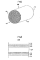
- FIG. 1 schematically shows a honeycomb structure according to an embodiment of the present invention.
- FIG. 2 schematically shows an example of a honeycomb unit which is a basic configuration unit of the honeycomb structure in FIG. 1 .
- the honeycomb structure 100 has two opening faces 110 and 115.
- a coating layer 120 is formed on an outer peripheral surface but is not formed on the two opening faces of the honeycomb structure 100.
- the honeycomb structure 100 may be formed in a manner so that plural honeycomb units 130 each having a pillar shape as shown in FIG. 2 are joined with each other (in FIG. 1 , 4 by 4 matrix (16 units)) by interposing adhesive layers 150, dried and solidified, and cut around the outer peripheral according to a prescribed shape (in the example of FIG. 1 , a cylindrical shape).
- the honeycomb unit 130 has plural cells (through holes) 121 and cell walls 123 dividing the cells, each cell extending in the longitudinal direction of the honeycomb unit 130 from one end face to the other end face and having openings one on each end face.
- FIG. 4 schematically shows an enlarged cross section of the cell wall in a conventional honeycomb structure.
- a cell wall 123P of a honeycomb unit 130P includes cordierite. Further, an NOx adsorption layer 210 and an ammonia adsorption layer 220 are formed on the cell wall 123P of the honeycomb unit 130P.
- the NOx adsorption layer 210 includes ceria and a noble metal catalyst such as platinum.
- the ammonia adsorption layer 220 is formed outside of the NOx adsorption layer 210 and typically includes material such as zeolite. It is obvious for a person having ordinary skill in the art that each of the NOx adsorption layer 210 and the ammonia adsorption layer 220 is not uniformly (continuously) formed as a "layer" as shown in FIG. 4 . Therefore, it should be noted that FIG. 4 is a symbolic view for illustrative purposes only.
- the NOx in the exhaust gas is adsorbed in the NOx adsorption layer 210.
- rich-spiking is carried out so that the exhaust gas is in a reducing atmosphere.
- the HC is converted by a catalyst so that the generated H 2 and the NOx adsorbed in the NOx adsorption layer 210 react to generate ammonia according to the following reaction in Formula (1) 2NO + 3H 2 ⁇ 2NH 3 + O 2 Formula (1)
- the ammonia generated in this reaction is adsorbed in the ammonia adsorption layer 220 adjacent to the NOx adsorption layer 210.
- the NOx in the exhaust gas can be converted by the function of the NOx adsorption layer 210 and the ammonia adsorption layer 220 each supported on the cell walls 123P of the honeycomb structure.
- the cordierite itself included in the cell walls 123P does not react in the NOx conversion reaction. In other words, it is necessary to carry out all the reactions for converting the NOx in the exhaust gas only by the two layers, the NOx adsorption layer 210 and the ammonia adsorption layer 220 each supported on the cell walls 123P. Therefore, to increase the efficiency of converting NOx in the honeycomb structure, it is necessary to support sufficient amounts of the NOx adsorption layer 210 and the ammonia adsorption layer 220 on the cell walls 123P. To this end, it is necessary to increase the thicknesses of the two layers 210 and 220 or to elongate the whole length of the cordierite which is a supporting body. Otherwise, it is necessary to increase the frequency of a rich-spiking operation.
- the cell walls include materials different from those in the conventional honeycomb structure.
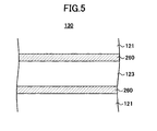
- FIG. 5 shows a schematic enlarged view of a cross section of the cell wall of the honeycomb structure according to an embodiment of the present invention.
- the cell wall 123 of the honeycomb unit 130 includes a material (such as ceria) capable of adsorbing NOx and a material (such as zeolite) capable of adsorbing ammonia.
- the cell wall 123 includes a mixture of ceria and zeolite, and a noble metal catalyst (such as platinum) is supported on the cell wall.
- a preliminary layer 260 is formed on the surface of the cell wall 123.
- the preliminary layer 260 includes, for example, zeolite.
- FIG. 5 it is illustrated that the preliminary layer 260 is uniformly formed as a "layer". However, as described with reference to FIG. 4 above, it is obvious that the preliminary layer 260 is not uniformly (continuously) formed as a "layer".
- the cell walls 123 including such materials do not include cordierite that does not contribute to the NOx conversion reaction unlike the conventional honeycomb structure. Therefore, it becomes possible to use all the materials included in the honeycomb structure 100 (namely, in the honeycomb unit 130) for the NOx conversion reaction. Therefore advantageously, it becomes possible to significantly improve the NOx conversion capability.
- the honeycomb structure according to an embodiment of the present invention since a necessary and sufficient amount of a material for adsorbing NOx and a material for adsorbing ammonia are included, it is not necessary to increase the thicknesses of the NOx adsorption layer and the ammonia adsorption layer on the cell walls 123P, to extend the total length of the honeycomb structure, or to increase the frequency of the rich-spiking operation. Therefore advantageously, in the honeycomb structure according to an embodiment of the present invention, it becomes possible to reduce the weight, the size, and the fuel consumption.
- the preliminary layer 260 formed on the surface of the cell walls 123 adsorbs ammonia like a conventional ammonia adsorption layer 220.
- the preliminary layer 260 is just a member preliminarily provided for ensuring that ammonia is not exhausted outside the honeycomb structure.
- the cell walls 123 of the honeycomb structure already includes a material contributing to the adsorption of ammonia, so that most of ammonia generated in the above-mentioned NOx conversion process is adsorbed in the ammonia adsorption material in a skeleton structure part of the cell walls 123.
- the preliminary layer 260 adsorbs the small amount of ammonia that has not be adsorbed in the cell walls 123, so as to ensure that the ammonia generated in a reaction process is not exhausted outside of the honeycomb structure. Therefore, in the honeycomb structure 100 according to an embodiment of the present invention, the thickness of the preliminary layer 260 can be made sufficiently less than that of the conventional ammonia adsorption layer 220.
- the honeycomb structure according to an embodiment of the present invention can maintain stable NOx conversion performance for a period longer than a conventional honeycomb structure does due to the following reasons.
- the zeolite used in the ammonia adsorption layer 220 in a conventional honeycomb structure is likely to absorb water vapor in a high temperature environment, which may cause a hydrolysis reaction of ammonia.
- the aluminum is desorption from the zeolite, thereby degrading the ammonia adsorption capability of the ammonia adsorption layer 220.
- the NOx conversion performance is degraded over time.
- the zeolite in the cell walls is adjacent to the ceria on which a noble metal catalyst is supported. Because of this feature, the water vapor preferentially reacts with the noble metal catalyst on the ceria rather than with the zeolite, which makes it difficult to cause the hydrolysis reaction of ammonia. Therefore, in the honeycomb structure according to an embodiment of the present invention, it is possible to maintain stable NOx conversion performance for a longer period of time.
- the compounding ratio (weight ratio) of the material (such as ceria) for adsorbing the NOx in the cell walls to the material (such as zeolite) for adsorbing the ammonia is in the range of from 2:1 to 10:1. From a stoichiometric viewpoint, when the compounding ratio of the two materials is within this range, the ammonia generated with the NOx adsorption material can be effectively adsorbed by the ammonia adsorption material.
- the amount of the preliminary layer 260 coated on the cell walls 123 is in the range of 5 g/L to 15 g/L.
- the honeycomb unit 130 includes inorganic binder in addition to the ceria particles and the zeolite particles.
- the honeycomb unit 130 according to an embodiment of the present invention may further include inorganic fibers.
- inorganic sol and a clay binder and the like may be used as the material of the inorganic binder.
- the specific examples of the inorganic sol is alumina sol, silica sol, titania sol, water glass and the like.
- the specific examples of the clay binders is double chain structural type clay such as white clay, kaolin, montmorillonite, sepiolite, attapulgite and the like. Any of these may be used alone or in combination of two or more kinds.
- a material of the inorganic fibers is alumina, silica, silicon carbide, silica-alumina, glass, potassium titanate, aluminum borate and the like. Any of these may be used alone or in combination of two or more. Among the above materials, more preferably, aluminum borate is used.
- the inorganic fibers include whiskers.
- the lower limit of a total amount of ceria particles and zeolite particles in the honeycomb unit is preferably 30 wt%, more preferably 40 wt%, and still more preferably 50 wt%.
- the upper limit of the total amount of ceria particles and zeolite particles in the honeycomb unit is preferably 90 wt% and more preferably 80 wt%.
- the inorganic binder content as solids content is preferably equal to or more than 5 wt%, more preferably equal to or more than 10 wt%, and still more preferably equal to or more than 15 wt%.
- the inorganic binder content as solids content is preferably equal to or less than 50 wt%, more preferably equal to or less than 40 wt%, and still more preferably equal to or less than 35 wt%.
- the inorganic binder content as solids content is less than 5 wt%, the strength of the manufactured honeycomb unit may be reduced.
- the inorganic binder content as solids content exceeds 50 wt%, the molding capability of the raw material composition may be degraded.
- the lower limit of the total amount of the inorganic fibers is preferably 3 wt%, more preferably 5 wt%, and still more preferably 8 wt%.
- the upper limit of the total amount of the inorganic fibers is preferably 50 wt%, more preferably 40 wt%, and still more preferably 30 wt%.
- the inorganic fibers content is less than 3 wt%, the effect of improving the strength of the honeycomb unit is small.
- the inorganic fibers content exceeds 50 wt%, the amount of ceria particles and zeolite particles each contributing to the NOx conversion is relatively reduced. As a result, the NOx conversion performance may be degraded.
- the shape of the cross section perpendicular to the longitudinal direction of the honeycomb unit 130 is not specifically limited, but any shape may be used as long as the shape allows the honeycomb units to join with each other by interposing adhesive layers.
- the honeycomb unit 130 may have any shape including a square, a rectangle, a hexagon, a fan shape and the like.
- the shape of the cross section perpendicular to the longitudinal direction of the cell 121 of the honeycomb unit 130 is not specifically limited, but may be a triangle, a polygonal shape and the like in addition to a square.
- the cell density of the honeycomb unit 130 is preferably in the range of 15.5 units/cm 2 to 186 units/cm 2 (100 cpsi to 1200 cpsi), more preferably in the range of 46.5 units/cm 2 to 170 units/cm 2 (300 cpsi to 1100 cpsi), and still more preferably in the range of 62.0 units/cm 2 to 155 units/cm 2 (400 cpsi to 1000 cpsi).
- the thickness of the cell wall 123 of the honeycomb unit 130 (before a noble metal catalyst is supported) is not specifically limited, but the lower limit and the upper limit of the thickness of the cell wall 123 of the honeycomb unit 130 is preferably 0.1 mm and 0.4 mm, respectively.
- the honeycomb structure 100 may have any shape including a cylindroid shape, a square pillar shape, a hexagonal pillar shape and the like in addition to a pillar shape as shown in FIG. 1 .
- the coating layer 120 of the honeycomb structure 100 is formed of a paste (coating layer paste) including inorganic particles, inorganic fibers, inorganic binder, and organic binder as the raw material.
- a paste coating layer paste
- the particles of alumina, silica, zirconia, titania, ceria, mullite, zeolite, or the like are used. Any of these may be used alone or in combination of two or more kinds.
- the inorganic fibers and the inorganic binder the above-mentioned material may be used.
- the organic binder polyvinyl alcohol, methylcellulose, ethylcellulose, carboxymethylcellulose, or the like may be used. Any of these may be used alone or in combination by combining two or more kinds.
- the organic binder more preferably, carboxymethylcellulose is used.
- the coating layer paste is applied on an outer peripheral surface of the honeycomb structure, and is dried and solidified to form the coating layer.
- a pore-forming agent such as balloons which is a micro sized hollow sphere having oxide-based ceramic as a component, spherical acrylic particles, graphite or the like may be added to the paste as the raw material.
- the thickness of the coating layer is preferably in the range of 0.1 mm to 0.2 mm.
- the same materials are used in both the adhesive layer 150 and the coating layer 120.
- the materials used in the adhesive layer 150 may be different from those in the coating layer 120, and the compounding ratio of the materials in the in the adhesive layer 150 may be different from that in the coating layer 120.
- Such a honeycomb structure 100 may be used in a treatment apparatus for exhaust gas exhausted from a diesel engine and the like.
- a honeycomb unit molded body is manufactured by extrusion molding and the like using a raw material paste including inorganic particles (ceria particles and zeolite particles) and inorganic binder as a main component and inorganic fibers added when necessary.
- a raw material paste including inorganic particles (ceria particles and zeolite particles) and inorganic binder as a main component and inorganic fibers added when necessary.
- organic binder As the raw material paste, organic binder, dispersion medium, and molding aid may be adequately added to the above materials in accordance with desired moldability.
- the kind of the organic binder is not specifically limited, but may be one or a combination of methylcellulose, carboxymethylcellulose, hydroxyethelcellulose, polyethyleneglycol, phenol resin, epoxy resin, and the like.
- the compounding amount of the organic binder is preferably in the range 1 part by weight to 10 parts by weight with respect to the total 100 parts by weight of the inorganic particles, inorganic binder, and inorganic fibers.
- the dispersion medium is not specifically limited, but may be water, organic solvent (such as benzene), alcohol (such as methanol), and the like.
- the molding aid is not specifically limited, but may be ethylene glycol, dextrin, fatty acid, fatty acid soap, polyalcohol, and the like.
- the raw material paste be mixed and kneaded.
- An apparatus such as a mixer or an attritor may be used for the mixing, and an apparatus such as a kneader may be used for the kneading.
- a method of forming the raw material paste is not specifically limited, but it is preferable to form a shape including the cell by, for example, extrusion molding.
- the thus-obtained molded body is dried.
- a drying apparatus is not specifically limited, but is used a microwave drying apparatus, a hot air drying apparatus, a dielectric drying apparatus, reduced pressure drying apparatus, vacuum drying apparatus, a freeze drying apparatus and the like.
- the obtained molded body is degreased.
- the degreasing condition is not specifically limited and is to be selected in accordance with a kind or amount of organic substance included in the molded body, but is preferably heated at a temperature of 400 °C for two hours.
- the obtained molded body is fired.
- the firing condition is not specifically limited but is preferably in the range of 600 °C to 1200 °C, and more preferably in the range of 600 °C to 1000 °C.
- a noble metal catalyst is supported on the cell walls of the obtained honeycomb unit.
- the noble metal catalyst is not specifically limited, but may be platinum, palladium, rhodium, and the like.
- the noble metal catalyst is supported on the cell walls by, for example, impregnating the honeycomb unit with nitric acid solution including platinum ions.
- the noble metal catalyst By supporting the noble metal catalyst on the cell walls of the obtained honeycomb unit, the noble metal catalyst is supported on the inorganic particles in the honeycomb unit. It should be noted that the noble metal catalyst is supported on the inorganic binder component as well in the honeycomb unit.
- the preliminary layer is coated on the cell walls of the honeycomb unit.
- the preliminary layer includes zeolite.
- the preliminary layer is formed by being coated on each cell wall.
- an adhesive layer paste which becomes an adhesive layer later is uniformly applied on a side surface of the honeycomb unit obtained by the above process.
- the other honeycomb units are sequentially joined with each other by interposing the adhesive layer paste. This process is repeated to manufacture a honeycomb structure having a desired size (for example, 4 by 4 matrix of honeycomb units).
- the adhesive layer paste is not specifically limited, but may be a mixture of inorganic binder and inorganic particles, a mixture of inorganic binder and inorganic fibers, a mixture of inorganic binder, inorganic particles, and inorganic fibers, or the like. Further, the adhesive layers paste may include organic binder.
- the organic binder is not specifically limited, but may be polyvinyl alcohol, methylcellulose, ethylcellulose, carboxymethylcellulose, and the like or a combination thereof.
- the thickness of the adhesive layer for joining the honeycomb units with each other is preferably in the range of 0.3 mm to 2 mm. When the thickness of the adhesive layers is less than 0.3 mm, sufficient bonding strength may not be obtained. On the other hand, when the thickness of the adhesive layers exceeds 2 mm, the pressure loss may be increased. It should be noted that the number of honeycomb units is appropriately selected in accordance with the size of the honeycomb structure.
- the honeycomb structure is heated so that the adhesive layer paste is dried and solidified to form the adhesive layer and join the honeycomb units with each other.
- the honeycomb structure is cut into, for example, a cylindrical shape by using a diamond cutter to manufacture a honeycomb structure having a desired outer peripheral shape.
- a coating layer paste is applied on the outer peripheral surface (side surface) of the honeycomb structure. Then the coating layer paste is dried and solidified to form the coating layer.
- the coating layer paste is not specifically limited, but may be the same as or different from the adhesive layer paste. Further, the compounding ratio of the materials in the in the coating layer paste may be the same as or different from that in the adhesive layer paste.
- the thickness of the coating layer is not specifically limited.
- honeycomb structure After plural honeycomb units are joined with each other by the interposing adhesive layers (or after the coating layer is formed when the coating layer is applied), it is preferable to degrease the assembly (honeycomb structure). By doing this process, when the adhesive layer paste and the coating layer paste include organic binder, the organic binder can be removed.
- the degreasing condition is to be selected in accordance with a kind or amount of organic substance included in the pastes, but is generally heated at a temperature of 400 °C for about two hours.
- honeycomb structure having plural honeycomb units as shown in FIG. 1 is described above.
- the present invention is not limited to the honeycomb structure as shown in FIG. 1 .
- a honeycomb structure may have a single honeycomb unit as shown in FIG. 3 .
- the coating layer may be or may not be formed.
- ceria particles average particle diameter: 2 ⁇ m
- 750 parts by weight of zeolite particles average particle diameter: 2 ⁇ m
- 345 parts by weight of alumina fibers average fiber diameter: 6 ⁇ m; average fiber length: 100 ⁇ m
- 2200 parts by weight of alumina sol solid concentration: 20 wt%
- 320 parts by weight of methylcellulose as organic binder, a small amount of a plasticizing agent, a surface-activating agent, and a lubricant agent are added to the mixture and are mixed and kneaded to obtain a mixed composition.
- the mixed composition is extrusion molded by using an extrusion molding apparatus to obtain a raw molded body.
- the raw molded body is fully dried by using a microwave drying apparatus and a hot air drying apparatus, then degreased at a temperature of 400 °C for two hours, and then fired at a temperature of 700 °C for two hours to obtain a porous honeycomb unit having a square pillar shape(sizes: 35 mm (breadth) x 35 mm (width) x 150mm (length)).
- the cell density of the porous honeycomb unit is 93 units/cm 2 . and thickness of the partition walls is 0.2 mm.
- the porous honeycomb unit having a square pillar shape is cut along the axis directions by using a diamond cutter to obtain an evaluation sample of a porous honeycomb unit having a cylindrical shape (sizes: 25 mm (diameter) x 60 mm (length)).
- the thus-obtained porous honeycomb unit (evaluation sample) having a cylindrical shape is impregnated with platinum nitrate solution, and then is heated at a temperature of 600 °C for one hour to support platinum on the cell walls.
- the platinum weight per unit volume in the honeycomb unit having a cylindrical shape is 3 g/L.
- the thus-obtained honeycomb unit having a cylindrical shape is wash-coated with zeolite slurry, and then is heated at a temperature of 600 °C for one hour.
- the preliminary layer including zeolite is coated on the cell walls.
- the coating weight of zeolite per unit volume is 5.0 g/L.
- Example 2 a honeycomb unit of Example 2 (evaluation sample) is manufactured.
- the coating weight of zeolite in the preliminary layer is 10.0 g/L.
- Example 3 a honeycomb unit of Example 3 (evaluation sample) is manufactured.
- the coating weight of zeolite in the preliminary layer is 15.0 g/L.
- Example 4 a honeycomb unit of Example 4 (evaluation sample) is manufactured.
- 2250 parts by weight of ceria particles average particle diameter: 2 ⁇ m
- 500 parts by weight of zeolite particles average particle diameter: 2 ⁇ m
- the other conditions are the same as in Example 1.
- Example 5 a honeycomb unit of Example 5 (evaluation sample) is manufactured.
- the coating weight of zeolite in the preliminary layer is 10.0 g/L.
- Example 6 the coating weight of zeolite in the preliminary layer is 15.0 g/L.
- Comparative example 1 evaluation sample
- 2700 parts by weight of ceria particles average particle diameter: 2 ⁇ m
- no zeolite particles are added.
- a zeolite preliminary layer is not coated on the surface of the cell walls.
- a honeycomb unit of Comparative example 2 (evaluation sample) is manufactured.
- 2200 parts by weight of ceria particles (average particle diameter: 2 ⁇ m) and 500 parts by weight of zeolite particles (average particle diameter: 2 ⁇ m) are used to form the honeycomb unit.
- a zeolite preliminary layer is not coated on the surface of the cell walls.
- Table 1 collectively shows the data of the compounding amount (parts by weight) of the materials (ceria and zeolite) and the coating amount of the zeolite preliminary layer of the honeycomb units with respect to each of the Examples and Comparative examples.
- COMPOUNDING AMOUNT PARTS BY WEIGHT
- COATING AMOUNT OF PRELIMINARY LAYER g/L
- NOx CONVERSION RATE %
- 2000 750 5.0 97 94 85 NO EXAMPLE 2 2000 750 10.0 97 95 85 NO EXAMPLE 3 2000 750 15.0 97 94 85 NO EXAMPLE 4 2250 500 5.0 93 87 82 NO EXAMPLE 5
- 2250 500 10.0 93 88 82 NO EXAMPLE 6 2250 500 15.0 93 88 82 NO COMPARATIVE EXAMPLE 1 2700 -- -- 90 87 76 YES COMPARATIVE EXAMPLE 2
- the NOx conversion performance with respect to Examples 1 through 6 and Comparative examples 1 and 2 is evaluated by using the corresponding evaluation samples prepared by the above-mentioned methods.
- the mixed gas simulating the lean operating condition and the mixed gas simulating the rich-spiking operating condition are introduced in each honeycomb unit so as to carry out the NOx conversion. Then, the NO (nitric oxide) amount in the gas exhausted from each honeycomb structure is measured.
- Table 2 shows the composition of the two kinds of the mixed gas simulating the lean and rich-spiking operations, respectively.
- the lean gas is introduced in the honeycomb structure for 55 seconds and then the rich gas introduced for 5 second. This cycle is repeated until the NO concentration in the exhaust gas becomes almost stable.
- GAS COMPOSITION GAS CONCENTRATION IN LEAN OPERATION IN RICH-SPIKING OPERATION CO 2 6vol% 6vol% O 2 6vol% -- NO 110ppm 110ppm CO 500ppm 2%
- THC HYDRO CARBON
- NO concentration is measured by using "MEXA-7100D” (HORIBA Ltd.) having an NO detection limit of 0.1 ppm.
- the temperature (of the honeycomb units and the simulation gas) during the evaluations is maintained at a temperature of 200 °C, 300 °C, or 400 °C.
- N % NO concentration of mixed gas before the mixed gas is introduced in honeycomb unit - NO concentration of the exhaust gas exhausted from the honeycomb unit / NO concentration of mixed gas before the mixed gas is introduced in honeycomb unit ⁇ 100
- the ammonia amount in the gas exhausted from each of the honeycomb units is measured.
- the ammonia detecting apparatus "MEXA-1170NX” HORIBA Ltd. having a measurement limit of 0.1 ppm is used.
- the honeycomb structure according to an embodiment of the present invention improves the NOx conversion performance and shows an excellent characteristic without exhausting ammonia.
Abstract
Description
- The present invention relates to a honeycomb structure.
- Conventionally, a honeycomb structure has been used in an exhaust gas treatment apparatus for converting, for example, NOx in exhaust gas from a vehicle (see, for example, Japanese Patent Application Publication No.
2006-183477 - The honeycomb structure has, for example, plural cells (through holes) extending from one end surface to the other end face along the longitudinal direction of the honeycomb structure. These cells are separated from each other by interposing cell walls.
- The cell wall of the honeycomb structure includes, for example, ceramic such as cordierite, and is provided with an NOx adsorption layer and an ammonia adsorption layer. In the NOx adsorption layer, for example, ceria is used, and a catalyst such as platinum is supported on this layer. In the ammonia adsorption layer, for example, zeolite is used.
- When exhaust gas from, for example, a vehicle is introduced in such a honeycomb structure, the NOx in the exhaust gas is adsorbed in the NOx adsorption layer in an oxidant atmosphere (for example, in a normal operation of a diesel engine), and then, in a reducing atmosphere (for example, in spiking of the diesel engine), the adsorbed NOx on the catalyst is reduced into ammonia, which is adsorbed in the ammonia adsorption layer. When the exhaust gas is in the oxidant atmosphere again, NOx is reduced by the ammonia. When the adsorbed ammonia is used up, NOx is adsorbed in the NOx adsorption layer. The NOx is converted due to this cycle.
- Therefore, it is possible to convert NOx in exhaust gas when exhaust gas is introduced in the honeycomb structure.
- In a conventional honeycomb structure, as described above, cordierite has been used as the base (skeleton) material, and the NOx adsorption layer and the ammonia adsorption layer are formed on a surface of the cell walls including the cordierite.
- However, the cordierite itself as the base (skeleton) material for the conventional honeycomb structure does not react in the reaction of converting NOx. In other words, all the converting reaction is carried out by the two layers: the NOx adsorption layer and the ammonia adsorption layer. Therefore, to increase the efficiency of converting NOx in the honeycomb structure, it is necessary to support a sufficient amount of the NOx adsorption layer and the ammonia adsorption layer formed on the cell walls. To this end, it is necessary to increase the thicknesses of the two layers or to elongate the whole length of the cordierite. Otherwise, it is necessary to increase the frequency of a rich-spiking operation.
- However, when the thicknesses of the layers are increased, the size of the openings of the cell walls becomes smaller. As a result, when exhaust gas is introduced, a pressure loss is disadvantageously increased. Further, when the total length of the cordierite is extended, there arises a problem of installation space and the weight. Further, when the frequency of the rich-spiking operation is increased, the fuel consumption is disadvantageously increased.
-
US 5116586 discloses the preparation of a full catalyst honeycomb structure consisting of honeycomb bodies with parallel conduits having a quadratic cross section. The honeycomb structure is extruded with a mixture of H-mordenite, i.e. zeolite, in which copper is ion exchange, cerium oxide, titanium dioxide, alkali free clay, glass fibers, aqueous ammonia solution, lactic acid, wood pulp, polyethylene oxide and carboxymethyl cellulose. - The present invention is made in light of the above circumstances and may provide a honeycomb structure having an excellent NOx conversion performance without increasing the thicknesses of the NOx adsorption layer and the ammonia adsorption layer on the cell walls and extending the total length of the cell walls. This is achieved by providing a honeycomb structure according to claim 1. Preferred embodiments are set forth in the dependent claims.
- K. Krishna and Al.: "Very active CeO2-zeolite catalysts for NOx reduction with NH3", Chem. Commun., 2002, 2030-2031 discloses CeO2-zeolite catalysts comprising 75 wt.% CeO2 and 25 wt.% H-zeolite, in order to improve NOx conversion.
-
EP 1142619 discloses a ceramic filter assembly having improved exhaust gas processing efficiency. The ceramic filter assembly is produced by adhering with a ceramic seal layer outer surfaces of a plurality of filters, each of which is formed from a sintered porous ceramic body. Filter assembly as a seal layer having a thickness of 0.3 mm to 3 mm and a thermal conductance of 0.1 W/mk to 10 W/mk. - Further, the weight ratio of the second material to the third material may be in the range of from 10:1 to 20:1.
- Further, the third material may be the same as the second material.
- Further, the second material may be zeolite in which any one of Fe, Cu, Ni, Zn, Mn, and Co is ion-exchanged.
- Further, the inorganic binder may include any one selected from a group consisting of alumina sol, silica sol, titania sol, water glass, sepiolite, and attapulgite.
- Further, the honeycomb structure may further include inorganic fibers.
- Further, the inorganic fibers may be any one selected from a group consisting of alumina, silica, silicon carbide, silica-alumina, glass, potassium titanate, and aluminum borate.
- Further, a noble metal catalyst may be supported on the inorganic particles.
- Further, plural honeycomb units each having a pillar shape and adhesive layers for joining the honeycomb units with each other may be included in the honeycomb structure.
- According to an embodiment of the present invention, there is provided a honeycomb structure having an excellent NOx conversion performance without increasing the thickness of the NOx adsorption layer and the ammonia adsorption layer on the cell walls and extending the total length of the cell walls.
- Other objects, features, and advantages of the present invention will become more apparent from the following description when read in conjunction with the accompanying drawings, in which:
-
FIG. 1 is a schematic perspective view showing an example of a honeycomb structure according to an embodiment of the present invention; -
FIG. 2 is a schematic perspective view showing an example of a honeycomb unit included in the honeycomb structure inFIG. 1 ; -
FIG. 3 a schematic perspective view showing another example of a honeycomb structure according to an embodiment of the present invention; -
FIG. 4 is a schematic view showing a cross-sectional structure of the cell wall of a conventional honeycomb structure; and -
FIG. 5 is a schematic view showing a cross-sectional structure of the cell wall of a honeycomb structure according to an embodiment of the present invention. - Next, an exemplary embodiment of the present invention is described with reference to the accompanying drawings.
-
FIG. 1 schematically shows a honeycomb structure according to an embodiment of the present invention.FIG. 2 schematically shows an example of a honeycomb unit which is a basic configuration unit of the honeycomb structure inFIG. 1 . - As shown in
FIG. 1 , thehoneycomb structure 100 according to an embodiment of the present invention has twoopening faces coating layer 120 is formed on an outer peripheral surface but is not formed on the two opening faces of thehoneycomb structure 100. - The
honeycomb structure 100 may be formed in a manner so thatplural honeycomb units 130 each having a pillar shape as shown inFIG. 2 are joined with each other (inFIG. 1 ,4 by 4 matrix (16 units)) by interposingadhesive layers 150, dried and solidified, and cut around the outer peripheral according to a prescribed shape (in the example ofFIG. 1 , a cylindrical shape). - As shown in
FIG. 2 , thehoneycomb unit 130 has plural cells (through holes) 121 andcell walls 123 dividing the cells, each cell extending in the longitudinal direction of thehoneycomb unit 130 from one end face to the other end face and having openings one on each end face. - To be able to understand more clearly about a characteristic effect of the
honeycomb structure 100 according to an embodiment of the present invention, an exemplary configuration of a conventional honeycomb structure is first described. -
FIG. 4 schematically shows an enlarged cross section of the cell wall in a conventional honeycomb structure. - In a conventional honeycomb structure, a
cell wall 123P of ahoneycomb unit 130P includes cordierite. Further, anNOx adsorption layer 210 and anammonia adsorption layer 220 are formed on thecell wall 123P of thehoneycomb unit 130P. TheNOx adsorption layer 210 includes ceria and a noble metal catalyst such as platinum. Theammonia adsorption layer 220 is formed outside of theNOx adsorption layer 210 and typically includes material such as zeolite. It is obvious for a person having ordinary skill in the art that each of theNOx adsorption layer 210 and theammonia adsorption layer 220 is not uniformly (continuously) formed as a "layer" as shown inFIG. 4 . Therefore, it should be noted thatFIG. 4 is a symbolic view for illustrative purposes only. - When a conventional honeycomb structure including such a material group is placed in a flow of exhaust gas so that the exhaust gas is practically introduced in the honeycomb structure, the following phenomena are observed.
- First, when the exhaust gas is in an oxidant atmosphere (for example, in a normal operation of a diesel engine), the NOx in the exhaust gas is adsorbed in the
NOx adsorption layer 210. Next, rich-spiking is carried out so that the exhaust gas is in a reducing atmosphere. The HC is converted by a catalyst so that the generated H2 and the NOx adsorbed in theNOx adsorption layer 210 react to generate ammonia according to the following reaction in Formula (1)
2NO + 3H2 → 2NH3 + O2 Formula (1)
The ammonia generated in this reaction is adsorbed in theammonia adsorption layer 220 adjacent to theNOx adsorption layer 210. - On the other hand, when the exhaust gas is in an oxidant atmosphere again, the NOx in the exhaust gas is reduced by the ammonia adsorbed in the
ammonia adsorption layer 220 according to the following reactions in Formulas (2-1) and (2-2).
4NH3 + 4NO + O2 → 4N2 + 6H20 Formula (2-1)
8NH3 + 6NO2 → 7N2 + 12H20 Formula (2-2)
Further, when the ammonia adsorbed in theammonia adsorption layer 220 is comsumed, the NOx is adsorbed in theNOx adsorption layer 210 again. By repeating a cycle like this, the NOx is reduced and the exhaust gas in which the NOx is reduced reaches the other end face of thecell 121 and then is exhausted from this end face of the honeycomb structure. - As described above, in a conventional honeycomb structure, the NOx in the exhaust gas can be converted by the function of the
NOx adsorption layer 210 and theammonia adsorption layer 220 each supported on thecell walls 123P of the honeycomb structure. - However, it is necessary to note that the cordierite itself included in the
cell walls 123P does not react in the NOx conversion reaction. In other words, it is necessary to carry out all the reactions for converting the NOx in the exhaust gas only by the two layers, theNOx adsorption layer 210 and theammonia adsorption layer 220 each supported on thecell walls 123P. Therefore, to increase the efficiency of converting NOx in the honeycomb structure, it is necessary to support sufficient amounts of theNOx adsorption layer 210 and theammonia adsorption layer 220 on thecell walls 123P. To this end, it is necessary to increase the thicknesses of the twolayers - However, when the thickness of each layer is increased, the size of the opening of the cell walls becomes smaller. As a result, when exhaust gas is introduced, a pressure loss is disadvantageously increased. Further, when the total length of the cordierite (cell walls) is extended, there may arise a problem of the installation space and the weight. Further, when the frequency of the rich-spiking operation is increased, the fuel consumption is disadvantageously increased.
- On the other hand, in a honeycomb structure according to an embodiment of the present invention, the cell walls include materials different from those in the conventional honeycomb structure.
-
FIG. 5 shows a schematic enlarged view of a cross section of the cell wall of the honeycomb structure according to an embodiment of the present invention. - In the
honeycomb structure 100 according to an embodiment of the present invention, thecell wall 123 of thehoneycomb unit 130 includes a material (such as ceria) capable of adsorbing NOx and a material (such as zeolite) capable of adsorbing ammonia. For example, in thehoneycomb unit 130, thecell wall 123 includes a mixture of ceria and zeolite, and a noble metal catalyst (such as platinum) is supported on the cell wall. Further, in thehoneycomb structure 100 according to an embodiment of the present invention, apreliminary layer 260 is formed on the surface of thecell wall 123. Thepreliminary layer 260 includes, for example, zeolite. In theFIG. 5 , it is illustrated that thepreliminary layer 260 is uniformly formed as a "layer". However, as described with reference toFIG. 4 above, it is obvious that thepreliminary layer 260 is not uniformly (continuously) formed as a "layer". - In the
honeycomb structure 100 according to an embodiment of the present invention, thecell walls 123 including such materials do not include cordierite that does not contribute to the NOx conversion reaction unlike the conventional honeycomb structure. Therefore, it becomes possible to use all the materials included in the honeycomb structure 100 (namely, in the honeycomb unit 130) for the NOx conversion reaction. Therefore advantageously, it becomes possible to significantly improve the NOx conversion capability. - Further, in the honeycomb structure according to an embodiment of the present invention, since a necessary and sufficient amount of a material for adsorbing NOx and a material for adsorbing ammonia are included, it is not necessary to increase the thicknesses of the NOx adsorption layer and the ammonia adsorption layer on the
cell walls 123P, to extend the total length of the honeycomb structure, or to increase the frequency of the rich-spiking operation. Therefore advantageously, in the honeycomb structure according to an embodiment of the present invention, it becomes possible to reduce the weight, the size, and the fuel consumption. - It should be noted that the
preliminary layer 260 formed on the surface of thecell walls 123 adsorbs ammonia like a conventionalammonia adsorption layer 220. Thepreliminary layer 260 is just a member preliminarily provided for ensuring that ammonia is not exhausted outside the honeycomb structure. Namely, according to an embodiment of the present invention, thecell walls 123 of the honeycomb structure already includes a material contributing to the adsorption of ammonia, so that most of ammonia generated in the above-mentioned NOx conversion process is adsorbed in the ammonia adsorption material in a skeleton structure part of thecell walls 123. If any of the ammonia should not be adsorbed in the skeleton structure part of thecell walls 123, thepreliminary layer 260 adsorbs the small amount of ammonia that has not be adsorbed in thecell walls 123, so as to ensure that the ammonia generated in a reaction process is not exhausted outside of the honeycomb structure. Therefore, in thehoneycomb structure 100 according to an embodiment of the present invention, the thickness of thepreliminary layer 260 can be made sufficiently less than that of the conventionalammonia adsorption layer 220. - Further advantageously, the honeycomb structure according to an embodiment of the present invention can maintain stable NOx conversion performance for a period longer than a conventional honeycomb structure does due to the following reasons. The zeolite used in the
ammonia adsorption layer 220 in a conventional honeycomb structure is likely to absorb water vapor in a high temperature environment, which may cause a hydrolysis reaction of ammonia. - When such a reaction occurs, the aluminum is desorption from the zeolite, thereby degrading the ammonia adsorption capability of the
ammonia adsorption layer 220. As a result, generally, the NOx conversion performance is degraded over time. On the other hand, in the honeycomb structure according to an embodiment of the present invention, the zeolite in the cell walls is adjacent to the ceria on which a noble metal catalyst is supported. Because of this feature, the water vapor preferentially reacts with the noble metal catalyst on the ceria rather than with the zeolite, which makes it difficult to cause the hydrolysis reaction of ammonia. Therefore, in the honeycomb structure according to an embodiment of the present invention, it is possible to maintain stable NOx conversion performance for a longer period of time. - In the
honeycomb unit 130 according to an embodiment of the present invention, it is preferable that the compounding ratio (weight ratio) of the material (such as ceria) for adsorbing the NOx in the cell walls to the material (such as zeolite) for adsorbing the ammonia is in the range of from 2:1 to 10:1. From a stoichiometric viewpoint, when the compounding ratio of the two materials is within this range, the ammonia generated with the NOx adsorption material can be effectively adsorbed by the ammonia adsorption material. - Further preferably, the amount of the
preliminary layer 260 coated on thecell walls 123 is in the range of 5 g/L to 15 g/L. - The
honeycomb unit 130 according to an embodiment of the present invention includes inorganic binder in addition to the ceria particles and the zeolite particles. Thehoneycomb unit 130 according to an embodiment of the present invention may further include inorganic fibers. - As the material of the inorganic binder, inorganic sol and a clay binder and the like may be used. The specific examples of the inorganic sol is alumina sol, silica sol, titania sol, water glass and the like. The specific examples of the clay binders is double chain structural type clay such as white clay, kaolin, montmorillonite, sepiolite, attapulgite and the like. Any of these may be used alone or in combination of two or more kinds.
- Among these materials, it is preferable to use at least one selected from a group consisting of alumina sol, silica sol, titania sol, water glass, sepiolite and attapulgite.
- Further, when inorganic fibers are further included in the honeycomb unit, preferably, a material of the inorganic fibers is alumina, silica, silicon carbide, silica-alumina, glass, potassium titanate, aluminum borate and the like. Any of these may be used alone or in combination of two or more. Among the above materials, more preferably, aluminum borate is used. The inorganic fibers include whiskers.
- The lower limit of a total amount of ceria particles and zeolite particles in the honeycomb unit is preferably 30 wt%, more preferably 40 wt%, and still more preferably 50 wt%. On the other hand, the upper limit of the total amount of ceria particles and zeolite particles in the honeycomb unit is preferably 90 wt% and more preferably 80 wt%. When the total amount of these particles is less than 30 wt%, the amount of the particles contributing to the NOx conversion is relatively reduced. Therefore, the NOx conversion performance may be degraded. On the other hand, when the total amount of these particles exceeds 90 wt%, the strength of the honeycomb unit may be reduced.
- The inorganic binder content as solids content is preferably equal to or more than 5 wt%, more preferably equal to or more than 10 wt%, and still more preferably equal to or more than 15 wt%. On the other hand, the inorganic binder content as solids content is preferably equal to or less than 50 wt%, more preferably equal to or less than 40 wt%, and still more preferably equal to or less than 35 wt%. When the inorganic binder content as solids content is less than 5 wt%, the strength of the manufactured honeycomb unit may be reduced. On the other hand, when the inorganic binder content as solids content exceeds 50 wt%, the molding capability of the raw material composition may be degraded.
- When the honeycomb unit includes inorganic fibers, the lower limit of the total amount of the inorganic fibers is preferably 3 wt%, more preferably 5 wt%, and still more preferably 8 wt%. On the other hand, the upper limit of the total amount of the inorganic fibers is preferably 50 wt%, more preferably 40 wt%, and still more preferably 30 wt%. When the inorganic fibers content is less than 3 wt%, the effect of improving the strength of the honeycomb unit is small. When the inorganic fibers content exceeds 50 wt%, the amount of ceria particles and zeolite particles each contributing to the NOx conversion is relatively reduced. As a result, the NOx conversion performance may be degraded.
- The shape of the cross section perpendicular to the longitudinal direction of the
honeycomb unit 130 is not specifically limited, but any shape may be used as long as the shape allows the honeycomb units to join with each other by interposing adhesive layers. Thehoneycomb unit 130 may have any shape including a square, a rectangle, a hexagon, a fan shape and the like. - Further, the shape of the cross section perpendicular to the longitudinal direction of the
cell 121 of thehoneycomb unit 130 is not specifically limited, but may be a triangle, a polygonal shape and the like in addition to a square. - The cell density of the
honeycomb unit 130 is preferably in the range of 15.5 units/cm2 to 186 units/cm2 (100 cpsi to 1200 cpsi), more preferably in the range of 46.5 units/cm2 to 170 units/cm2 (300 cpsi to 1100 cpsi), and still more preferably in the range of 62.0 units/cm2 to 155 units/cm2 (400 cpsi to 1000 cpsi). - The thickness of the
cell wall 123 of the honeycomb unit 130 (before a noble metal catalyst is supported) is not specifically limited, but the lower limit and the upper limit of the thickness of thecell wall 123 of thehoneycomb unit 130 is preferably 0.1 mm and 0.4 mm, respectively. - On the other hand, the
honeycomb structure 100 may have any shape including a cylindroid shape, a square pillar shape, a hexagonal pillar shape and the like in addition to a pillar shape as shown inFIG. 1 . - The
coating layer 120 of thehoneycomb structure 100 is formed of a paste (coating layer paste) including inorganic particles, inorganic fibers, inorganic binder, and organic binder as the raw material. As the inorganic particles, the particles of alumina, silica, zirconia, titania, ceria, mullite, zeolite, or the like are used. Any of these may be used alone or in combination of two or more kinds. As the inorganic fibers and the inorganic binder, the above-mentioned material may be used. Further, as the organic binder, polyvinyl alcohol, methylcellulose, ethylcellulose, carboxymethylcellulose, or the like may be used. Any of these may be used alone or in combination by combining two or more kinds. As the organic binder, more preferably, carboxymethylcellulose is used. - Then, the coating layer paste is applied on an outer peripheral surface of the honeycomb structure, and is dried and solidified to form the coating layer. When necessary, a pore-forming agent such as balloons which is a micro sized hollow sphere having oxide-based ceramic as a component, spherical acrylic particles, graphite or the like may be added to the paste as the raw material. The thickness of the coating layer is preferably in the range of 0.1 mm to 0.2 mm.
- Further, in the
honeycomb structure 100 according to an embodiment of the present invention, the same materials are used in both theadhesive layer 150 and thecoating layer 120. However, the materials used in theadhesive layer 150 may be different from those in thecoating layer 120, and the compounding ratio of the materials in the in theadhesive layer 150 may be different from that in thecoating layer 120. - Such a
honeycomb structure 100 may be used in a treatment apparatus for exhaust gas exhausted from a diesel engine and the like. - Next, a method of manufacturing the honeycomb structure according to an embodiment of the present invention is described.
- First, a honeycomb unit molded body is manufactured by extrusion molding and the like using a raw material paste including inorganic particles (ceria particles and zeolite particles) and inorganic binder as a main component and inorganic fibers added when necessary.
- As the raw material paste, organic binder, dispersion medium, and molding aid may be adequately added to the above materials in accordance with desired moldability. The kind of the organic binder is not specifically limited, but may be one or a combination of methylcellulose, carboxymethylcellulose, hydroxyethelcellulose, polyethyleneglycol, phenol resin, epoxy resin, and the like. The compounding amount of the organic binder is preferably in the range 1 part by weight to 10 parts by weight with respect to the total 100 parts by weight of the inorganic particles, inorganic binder, and inorganic fibers.
- The dispersion medium is not specifically limited, but may be water, organic solvent (such as benzene), alcohol (such as methanol), and the like. The molding aid is not specifically limited, but may be ethylene glycol, dextrin, fatty acid, fatty acid soap, polyalcohol, and the like.
- It is preferable that the raw material paste be mixed and kneaded. An apparatus such as a mixer or an attritor may be used for the mixing, and an apparatus such as a kneader may be used for the kneading. A method of forming the raw material paste is not specifically limited, but it is preferable to form a shape including the cell by, for example, extrusion molding.
- Next, preferably, the thus-obtained molded body is dried. A drying apparatus is not specifically limited, but is used a microwave drying apparatus, a hot air drying apparatus, a dielectric drying apparatus, reduced pressure drying apparatus, vacuum drying apparatus, a freeze drying apparatus and the like. Further preferably, the obtained molded body is degreased. The degreasing condition is not specifically limited and is to be selected in accordance with a kind or amount of organic substance included in the molded body, but is preferably heated at a temperature of 400 °C for two hours. Next, the obtained molded body is fired. The firing condition is not specifically limited but is preferably in the range of 600 °C to 1200 °C, and more preferably in the range of 600 °C to 1000 °C. This is because when the firing temperature is less than 600 °C, the progress of sintering may be difficult, thereby reducing the strength of the honeycomb unit. On the other hand, when the firing temperature exceeds 1200 °C, excessive progress of sintering may occur, thereby reducing the specific surface area per unit volume of the honeycomb unit.
- Next, a noble metal catalyst is supported on the cell walls of the obtained honeycomb unit. The noble metal catalyst is not specifically limited, but may be platinum, palladium, rhodium, and the like. The noble metal catalyst is supported on the cell walls by, for example, impregnating the honeycomb unit with nitric acid solution including platinum ions.
- By supporting the noble metal catalyst on the cell walls of the obtained honeycomb unit, the noble metal catalyst is supported on the inorganic particles in the honeycomb unit. It should be noted that the noble metal catalyst is supported on the inorganic binder component as well in the honeycomb unit.
- Next, the preliminary layer is coated on the cell walls of the honeycomb unit. The preliminary layer includes zeolite. The preliminary layer is formed by being coated on each cell wall.
- Next, an adhesive layer paste which becomes an adhesive layer later is uniformly applied on a side surface of the honeycomb unit obtained by the above process. Then, the other honeycomb units are sequentially joined with each other by interposing the adhesive layer paste. This process is repeated to manufacture a honeycomb structure having a desired size (for example, 4 by 4 matrix of honeycomb units).
- The adhesive layer paste is not specifically limited, but may be a mixture of inorganic binder and inorganic particles, a mixture of inorganic binder and inorganic fibers, a mixture of inorganic binder, inorganic particles, and inorganic fibers, or the like. Further, the adhesive layers paste may include organic binder. The organic binder is not specifically limited, but may be polyvinyl alcohol, methylcellulose, ethylcellulose, carboxymethylcellulose, and the like or a combination thereof.
- The thickness of the adhesive layer for joining the honeycomb units with each other is preferably in the range of 0.3 mm to 2 mm. When the thickness of the adhesive layers is less than 0.3 mm, sufficient bonding strength may not be obtained. On the other hand, when the thickness of the adhesive layers exceeds 2 mm, the pressure loss may be increased. It should be noted that the number of honeycomb units is appropriately selected in accordance with the size of the honeycomb structure.
- Next, the honeycomb structure is heated so that the adhesive layer paste is dried and solidified to form the adhesive layer and join the honeycomb units with each other.
- Then, the honeycomb structure is cut into, for example, a cylindrical shape by using a diamond cutter to manufacture a honeycomb structure having a desired outer peripheral shape.
- Next, a coating layer paste is applied on the outer peripheral surface (side surface) of the honeycomb structure. Then the coating layer paste is dried and solidified to form the coating layer. The coating layer paste is not specifically limited, but may be the same as or different from the adhesive layer paste. Further, the compounding ratio of the materials in the in the coating layer paste may be the same as or different from that in the adhesive layer paste. The thickness of the coating layer is not specifically limited.
- After plural honeycomb units are joined with each other by the interposing adhesive layers (or after the coating layer is formed when the coating layer is applied), it is preferable to degrease the assembly (honeycomb structure). By doing this process, when the adhesive layer paste and the coating layer paste include organic binder, the organic binder can be removed. The degreasing condition is to be selected in accordance with a kind or amount of organic substance included in the pastes, but is generally heated at a temperature of 400 °C for about two hours.
- By doing the above procedure, the honeycomb structure shown in
FIG. 1 is manufactured. - The honeycomb structure having plural honeycomb units as shown in
FIG. 1 is described above. The present invention is not limited to the honeycomb structure as shown inFIG. 1 . For example, a honeycomb structure may have a single honeycomb unit as shown inFIG. 3 . In this case, the coating layer may be or may not be formed. - Next, examples according to the present invention are described.
- First, 2000 parts by weight of ceria particles (average particle diameter: 2 µm), 750 parts by weight of zeolite particles (average particle diameter: 2 µm), 345 parts by weight of alumina fibers (average fiber diameter: 6 µm; average fiber length: 100 µm), and 2200 parts by weight of alumina sol (solid concentration: 20 wt%) are mixed to obtain a mixture. 320 parts by weight of methylcellulose as organic binder, a small amount of a plasticizing agent, a surface-activating agent, and a lubricant agent are added to the mixture and are mixed and kneaded to obtain a mixed composition. Then, the mixed composition is extrusion molded by using an extrusion molding apparatus to obtain a raw molded body.
- Next, the raw molded body is fully dried by using a microwave drying apparatus and a hot air drying apparatus, then degreased at a temperature of 400 °C for two hours, and then fired at a temperature of 700 °C for two hours to obtain a porous honeycomb unit having a square pillar shape(sizes: 35 mm (breadth) x 35 mm (width) x 150mm (length)). The cell density of the porous honeycomb unit is 93 units/cm2. and thickness of the partition walls is 0.2 mm.
- Next, the porous honeycomb unit having a square pillar shape is cut along the axis directions by using a diamond cutter to obtain an evaluation sample of a porous honeycomb unit having a cylindrical shape (sizes: 25 mm (diameter) x 60 mm (length)).
- Next, the thus-obtained porous honeycomb unit (evaluation sample) having a cylindrical shape is impregnated with platinum nitrate solution, and then is heated at a temperature of 600 °C for one hour to support platinum on the cell walls. The platinum weight per unit volume in the honeycomb unit having a cylindrical shape is 3 g/L.
- Next, the thus-obtained honeycomb unit having a cylindrical shape is wash-coated with zeolite slurry, and then is heated at a temperature of 600 °C for one hour. By doing this process, the preliminary layer including zeolite is coated on the cell walls. The coating weight of zeolite per unit volume is 5.0 g/L.
- Next, by doing the same method as in Example 1, a honeycomb unit of Example 2 (evaluation sample) is manufactured. However, in this Example 2, the coating weight of zeolite in the preliminary layer is 10.0 g/L.
- Next, by doing the same method as in Example 1, a honeycomb unit of Example 3 (evaluation sample) is manufactured. However, in this Example 3, the coating weight of zeolite in the preliminary layer is 15.0 g/L.
- Next, by doing the same method as in Example 1, a honeycomb unit of Example 4 (evaluation sample) is manufactured. However, in this Example 4, 2250 parts by weight of ceria particles (average particle diameter: 2 µm), 500 parts by weight of zeolite particles (average particle diameter: 2 µm) are used. The other conditions are the same as in Example 1.
- Next, by doing the same method as in Example 4, a honeycomb unit of Example 5 (evaluation sample) is manufactured. However, in this Example 5, the coating weight of zeolite in the preliminary layer is 10.0 g/L.
- Next, by doing the same method as in Example 4, a honeycomb unit of Example 6 (evaluation sample) is manufactured. However, in this Example 6, the coating weight of zeolite in the preliminary layer is 15.0 g/L.
- Next, by doing the same method as in Example 1, a honeycomb unit of Comparative example 1 (evaluation sample) is manufactured. However, in this Comparative example 1, 2700 parts by weight of ceria particles (average particle diameter: 2 µm) are used but no zeolite particles are added. Further, a zeolite preliminary layer is not coated on the surface of the cell walls.
- Next, by doing the same method as in Example 1, a honeycomb unit of Comparative example 2 (evaluation sample) is manufactured. However, in this Comparative example 2, 2200 parts by weight of ceria particles (average particle diameter: 2 µm) and 500 parts by weight of zeolite particles (average particle diameter: 2 µm) are used to form the honeycomb unit. Further, a zeolite preliminary layer is not coated on the surface of the cell walls.
- Table 1 collectively shows the data of the compounding amount (parts by weight) of the materials (ceria and zeolite) and the coating amount of the zeolite preliminary layer of the honeycomb units with respect to each of the Examples and Comparative examples.
[Table 1] COMPOUNDING AMOUNT (PARTS BY WEIGHT) COATING AMOUNT OF PRELIMINARY LAYER (g/L) NOx CONVERSION RATE (%) AMMONIA DETECTION CERIA ZEOLITE 200°C 300°C 400°C EXAMPLE 1 2000 750 5.0 97 94 85 NO EXAMPLE 2 2000 750 10.0 97 95 85 NO EXAMPLE 3 2000 750 15.0 97 94 85 NO EXAMPLE 4 2250 500 5.0 93 87 82 NO EXAMPLE 5 2250 500 10.0 93 88 82 NO EXAMPLE 6 2250 500 15.0 93 88 82 NO COMPARATIVE EXAMPLE 1 2700 -- -- 90 87 76 YES COMPARATIVE EXAMPLE 2 2200 500 -- 93 88 82 YES - The NOx conversion performance with respect to Examples 1 through 6 and Comparative examples 1 and 2 is evaluated by using the corresponding evaluation samples prepared by the above-mentioned methods. In the evaluation of the NOx conversion performance, the mixed gas simulating the lean operating condition and the mixed gas simulating the rich-spiking operating condition are introduced in each honeycomb unit so as to carry out the NOx conversion. Then, the NO (nitric oxide) amount in the gas exhausted from each honeycomb structure is measured.
- Table 2 shows the composition of the two kinds of the mixed gas simulating the lean and rich-spiking operations, respectively. In this evaluation, first, the lean gas is introduced in the honeycomb structure for 55 seconds and then the rich gas introduced for 5 second. This cycle is repeated until the NO concentration in the exhaust gas becomes almost stable.
[Table 2] GAS COMPOSITION GAS CONCENTRATION IN LEAN OPERATION IN RICH-SPIKING OPERATION CO2 6vol% 6vol% O2 6vol% -- NO 110ppm 110ppm CO 500ppm 2% THC (HYDRO CARBON) 900ppm* 900ppm* H2O 7vol% 7vol% N2 Balance Balance SV 50000/hr 47000/hr * CARBON AMOUNT CRITERION - NO concentration is measured by using "MEXA-7100D" (HORIBA Ltd.) having an NO detection limit of 0.1 ppm.
- The temperature (of the honeycomb units and the simulation gas) during the evaluations is maintained at a temperature of 200 °C, 300 °C, or 400 °C.
- To evaluate the NOx conversion performance, the NOx conversion rate "N" given as follows is used.

- Further, in addition to the evaluation of the NOx conversion performance, the ammonia amount in the gas exhausted from each of the honeycomb units is measured. To measure the ammonia amount, the ammonia detecting apparatus "MEXA-1170NX" (HORIBA Ltd.) having a measurement limit of 0.1 ppm is used.
- The results of the measurement are shown in the right end columns of Table 1. The results shows that each of the honeycomb units according to an embodiment of the present invention (evaluation samples of Example 1 through 6) has a higher NOx conversion rate than the honeycomb unit (evaluation sample) of Comparative sample 1 at any of the temperatures. Further, ammonia is detected in the exhaust gas from each honeycomb unit (evaluation sample) of Comparative examples 1 and 2. However, no ammonia is detected from any of the honeycomb units (evaluation samples) of Examples 1 through 6.
- As described above, the honeycomb structure according to an embodiment of the present invention improves the NOx conversion performance and shows an excellent characteristic without exhausting ammonia.
- The present application is based on and claims the benefit of priority of Japanese Patent Application No.
PCT/JP2008/055973, filed on March 27, 2008
Claims (11)
- A honeycomb structure comprising
a honeycomb unit having a pillar shape including
inorganic particles and inorganic binder, and cell walls defining plural cells each extending along the longitudinal direction from one end surface to the other end surface,
wherein
the cell walls includes a first material including NOx adsorption material and a second material including ammonia adsorption material; and
a third material including zeolite is coated on the cell walls. - The honeycomb structure according to claim 1, wherein
the first material includes ceria, and the second and the third materials include zeolite. - The honeycomb structure according to claim 1 or 2, wherein
the weight ratio of the first material to the second material is in the range of from 2:1 to 10:1. - The honeycomb structure according to any one of claims 1 through 3, wherein
the weight ratio of the second material to the third material is in the range of from 10:1 to 20:1. - The honeycomb structure according to any one of claims 1 through 4, wherein
the third material is substantially the same as the second material. - The honeycomb structure according to any one of claims 1 through 5, wherein
the second material is the zeolite in which any one of Fe, Cu, Ni, Zn, Mn, and Co is ion-exchanged. - The honeycomb structure according to any one of claims 1 through 6, wherein
the inorganic binder includes at least any one selected from a group consisting of alumina sol, silica sol, titania sol, water glass, sepiolite, and attapulgite. - The honeycomb structure according to any one of claims 1 through 7, wherein
the honeycomb unit includes inorganic fibers. - The honeycomb structure according to claim 8, wherein
the inorganic fibers is at least any one selected from a group consisting of alumina, silica, silicon carbide, silica-alumina, glass, potassium titanate, and aluminum borate. - The honeycomb structure according to any one of claims 1 through 9, wherein
a noble metal catalyst is supported on the inorganic particles. - The honeycomb structure according to any one of claims 1 through 10, wherein
the honeycomb structure has plural honeycomb units each having a pillar shape and adhesive layers for joining the honeycomb units with each other.
Applications Claiming Priority (1)
| Application Number | Priority Date | Filing Date | Title |
|---|---|---|---|
| PCT/JP2008/055973 WO2009118868A1 (en) | 2008-03-27 | 2008-03-27 | Honeycomb structure |
Publications (2)
| Publication Number | Publication Date |
|---|---|
| EP2105589A1 EP2105589A1 (en) | 2009-09-30 |
| EP2105589B1 true EP2105589B1 (en) | 2010-11-10 |
Family
ID=39870310
Family Applications (1)
| Application Number | Title | Priority Date | Filing Date |
|---|---|---|---|
| EP08015200A Not-in-force EP2105589B1 (en) | 2008-03-27 | 2008-08-28 | Honeycomb structure |
Country Status (5)
| Country | Link |
|---|---|
| US (1) | US20090246103A1 (en) |
| EP (1) | EP2105589B1 (en) |
| JP (1) | JPWO2009118868A1 (en) |
| AT (1) | ATE487857T1 (en) |
| WO (1) | WO2009118868A1 (en) |
Cited By (1)
| Publication number | Priority date | Publication date | Assignee | Title |
|---|---|---|---|---|
| CN106457216A (en) * | 2014-05-09 | 2017-02-22 | 庄信万丰股份有限公司 | Ammonia slip catalyst having platinum impregnated on high porosity substrates |
Families Citing this family (12)
| Publication number | Priority date | Publication date | Assignee | Title |
|---|---|---|---|---|
| WO2009141872A1 (en) * | 2008-05-20 | 2009-11-26 | イビデン株式会社 | Honeycomb structure |
| JP5563952B2 (en) * | 2009-11-19 | 2014-07-30 | イビデン株式会社 | Honeycomb structure and exhaust gas purification device |
| HUE027305T2 (en) | 2010-02-01 | 2016-10-28 | Johnson Matthey Plc | Oxidation catalyst |
| JP5419772B2 (en) * | 2010-03-26 | 2014-02-19 | 日本碍子株式会社 | Zeolite honeycomb structure |
| US9138731B2 (en) | 2011-08-03 | 2015-09-22 | Johnson Matthey Public Limited Company | Extruded honeycomb catalyst |
| PL3313570T3 (en) * | 2015-06-29 | 2021-12-27 | Corning Incorporated | Porous ceramic body to reduce emissions |
| JPWO2017057756A1 (en) * | 2015-10-02 | 2018-07-19 | 株式会社三徳 | Carbon dioxide adsorbent and molded body containing the same |
| JP6709652B2 (en) * | 2016-03-24 | 2020-06-17 | 日本碍子株式会社 | Porous ceramic structure |
| JP6684257B2 (en) * | 2017-09-27 | 2020-04-22 | イビデン株式会社 | Honeycomb catalyst for exhaust gas purification |
| JP6698602B2 (en) * | 2017-09-27 | 2020-05-27 | イビデン株式会社 | Honeycomb catalyst for exhaust gas purification |
| JP2019058875A (en) * | 2017-09-27 | 2019-04-18 | イビデン株式会社 | Honeycomb catalyst |
| JP2019058876A (en) | 2017-09-27 | 2019-04-18 | イビデン株式会社 | Honeycomb catalyst |
Citations (1)
| Publication number | Priority date | Publication date | Assignee | Title |
|---|---|---|---|---|
| JP2006183477A (en) * | 2004-12-27 | 2006-07-13 | Honda Motor Co Ltd | Exhaust emission control device for internal combustion engine |
Family Cites Families (17)
| Publication number | Priority date | Publication date | Assignee | Title |
|---|---|---|---|---|
| DE3841990A1 (en) * | 1988-12-14 | 1990-06-21 | Degussa | PROCESS FOR REDUCING STICK OXIDES FROM EXHAUST GASES |
| US6248684B1 (en) * | 1992-11-19 | 2001-06-19 | Englehard Corporation | Zeolite-containing oxidation catalyst and method of use |
| JP3516718B2 (en) * | 1994-07-05 | 2004-04-05 | 日本碍子株式会社 | Exhaust gas purification catalyst-adsorbent and exhaust gas purification method |
| US6667018B2 (en) * | 1994-07-05 | 2003-12-23 | Ngk Insulators, Ltd. | Catalyst-adsorbent for purification of exhaust gases and method for purification of exhaust gases |
| EP1516659B1 (en) | 1999-09-29 | 2006-12-13 | Ibiden Co., Ltd. | Honeycomb filter and ceramic filter assembly |
| JP4815108B2 (en) * | 2003-12-26 | 2011-11-16 | イビデン株式会社 | Honeycomb structure |
| WO2007000825A1 (en) * | 2005-06-27 | 2007-01-04 | Ibiden Co., Ltd. | Honeycomb structure body |
| JP2007296514A (en) * | 2006-04-07 | 2007-11-15 | Ngk Insulators Ltd | Catalytic body and manufacturing method of the same |
| WO2008059607A1 (en) * | 2006-11-16 | 2008-05-22 | Ibiden Co., Ltd. | Process for producing honeycomb structure and honeycomb structure |
| US20080118701A1 (en) * | 2006-11-16 | 2008-05-22 | Ibiden Co., Ltd. | Method for manufacturing honeycomb structure, and honeycomb structure |
| EP1923373B1 (en) * | 2006-11-16 | 2010-01-20 | Ibiden Co., Ltd. | Method for manufacturing honeycomb structured body |
| WO2008096413A1 (en) * | 2007-02-06 | 2008-08-14 | Ibiden Co., Ltd. | Honeycomb structure |
| DE502007003465D1 (en) * | 2007-02-23 | 2010-05-27 | Umicore Ag & Co Kg | Catalytically activated diesel particulate filter with ammonia barrier effect |
| WO2008126306A1 (en) * | 2007-03-30 | 2008-10-23 | Ibiden Co., Ltd. | Catalyst support |
| WO2008126305A1 (en) * | 2007-03-30 | 2008-10-23 | Ibiden Co., Ltd. | Catalyst carrier and exhaust gas treating apparatus |
| WO2008126307A1 (en) * | 2007-03-30 | 2008-10-23 | Ibiden Co., Ltd. | Catalyst support and process for producing the same |
| WO2008129670A1 (en) * | 2007-04-17 | 2008-10-30 | Ibiden Co., Ltd. | Catalyst-carrying honeycomb and process for producing the same |
-
2008
- 2008-03-27 WO PCT/JP2008/055973 patent/WO2009118868A1/en active Application Filing
- 2008-03-27 JP JP2008559003A patent/JPWO2009118868A1/en active Pending
- 2008-08-28 AT AT08015200T patent/ATE487857T1/en not_active IP Right Cessation
- 2008-08-28 EP EP08015200A patent/EP2105589B1/en not_active Not-in-force
- 2008-10-07 US US12/246,899 patent/US20090246103A1/en not_active Abandoned
Patent Citations (1)
| Publication number | Priority date | Publication date | Assignee | Title |
|---|---|---|---|---|
| JP2006183477A (en) * | 2004-12-27 | 2006-07-13 | Honda Motor Co Ltd | Exhaust emission control device for internal combustion engine |
Non-Patent Citations (1)
| Title |
|---|
| NAKATSUJI ET AL: "A NOx reduction system using ammonia-storage selective catalytic reduction in rich/lean excursions", APPLIED CATALYSIS B: ENVIRONMENTAL, ELSEVIER, vol. 77, no. 1-2, 15 November 2007 (2007-11-15), pages 190 - 201, XP022345987, ISSN: 0926-3373 * |
Cited By (1)
| Publication number | Priority date | Publication date | Assignee | Title |
|---|---|---|---|---|
| CN106457216A (en) * | 2014-05-09 | 2017-02-22 | 庄信万丰股份有限公司 | Ammonia slip catalyst having platinum impregnated on high porosity substrates |
Also Published As
| Publication number | Publication date |
|---|---|
| US20090246103A1 (en) | 2009-10-01 |
| ATE487857T1 (en) | 2010-11-15 |
| JPWO2009118868A1 (en) | 2011-07-21 |
| EP2105589A1 (en) | 2009-09-30 |
| WO2009118868A1 (en) | 2009-10-01 |
Similar Documents
| Publication | Publication Date | Title |
|---|---|---|
| EP2105589B1 (en) | Honeycomb structure | |
| EP1752203B1 (en) | Honeycomb structure | |
| US8034299B2 (en) | Catalyst carrier and exhaust gas treatment apparatus | |
| EP1739066B1 (en) | Honeycomb structure | |
| JP5528691B2 (en) | Honeycomb structure | |
| US8226898B2 (en) | Honeycomb structure and exhaust gas treatment apparatus | |
| US8048382B2 (en) | Honeycomb structure and exhaust gas treating apparatus | |
| US20100055386A1 (en) | Honeycomb structure | |
| US20090291827A1 (en) | Honeycomb structure | |
| WO2009141897A1 (en) | Honeycomb structure | |
| EP2130590A2 (en) | Honeycomb structure | |
| US8323766B2 (en) | Honeycomb structure | |
| EP2130588B1 (en) | Honeycomb structure | |
| US20090291841A1 (en) | Honeycomb structure | |
| EP2105423B1 (en) | Honeycomb structure | |
| EP2130599A2 (en) | Honeycomb structure | |
| EP2130589B1 (en) | Honeycomb structure | |
| US20090291828A1 (en) | Honeycomb structure | |
| EP2127725B1 (en) | Honeycomb structure and exhaust gas conversion apparatus | |
| EP2325149B1 (en) | Manufacturing method of honeycomb structural body | |
| KR101026968B1 (en) | Honeycomb structure |
Legal Events
| Date | Code | Title | Description |
|---|---|---|---|
| PUAI | Public reference made under article 153(3) epc to a published international application that has entered the european phase |
Free format text: ORIGINAL CODE: 0009012 |
|
| 17P | Request for examination filed |
Effective date: 20080828 |
|
| AK | Designated contracting states |
Kind code of ref document: A1 Designated state(s): AT BE BG CH CY CZ DE DK EE ES FI FR GB GR HR HU IE IS IT LI LT LU LV MC MT NL NO PL PT RO SE SI SK TR |
|
| AX | Request for extension of the european patent |
Extension state: AL BA MK RS |
|
| 17Q | First examination report despatched |
Effective date: 20091214 |
|
| AKX | Designation fees paid |
Designated state(s): AT BE BG CH CY CZ DE DK EE ES FI FR GB GR HR HU IE IS IT LI LT LU LV MC MT NL NO PL PT RO SE SI SK TR |
|
| GRAP | Despatch of communication of intention to grant a patent |
Free format text: ORIGINAL CODE: EPIDOSNIGR1 |
|
| GRAS | Grant fee paid |
Free format text: ORIGINAL CODE: EPIDOSNIGR3 |
|
| GRAA | (expected) grant |
Free format text: ORIGINAL CODE: 0009210 |
|
| AK | Designated contracting states |
Kind code of ref document: B1 Designated state(s): AT BE BG CH CY CZ DE DK EE ES FI FR GB GR HR HU IE IS IT LI LT LU LV MC MT NL NO PL PT RO SE SI SK TR |
|
| REG | Reference to a national code |
Ref country code: GB Ref legal event code: FG4D |
|
| REG | Reference to a national code |
Ref country code: CH Ref legal event code: EP |
|
| REG | Reference to a national code |
Ref country code: IE Ref legal event code: FG4D |
|
| REF | Corresponds to: |
Ref document number: 602008003400 Country of ref document: DE Date of ref document: 20101223 Kind code of ref document: P |
|
| REG | Reference to a national code |
Ref country code: NL Ref legal event code: VDEP Effective date: 20101110 |
|
| LTIE | Lt: invalidation of european patent or patent extension |
Effective date: 20101110 |
|
| PG25 | Lapsed in a contracting state [announced via postgrant information from national office to epo] |
Ref country code: NO Free format text: LAPSE BECAUSE OF FAILURE TO SUBMIT A TRANSLATION OF THE DESCRIPTION OR TO PAY THE FEE WITHIN THE PRESCRIBED TIME-LIMIT Effective date: 20110210 Ref country code: LT Free format text: LAPSE BECAUSE OF FAILURE TO SUBMIT A TRANSLATION OF THE DESCRIPTION OR TO PAY THE FEE WITHIN THE PRESCRIBED TIME-LIMIT Effective date: 20101110 |
|
| PG25 | Lapsed in a contracting state [announced via postgrant information from national office to epo] |
Ref country code: NL Free format text: LAPSE BECAUSE OF FAILURE TO SUBMIT A TRANSLATION OF THE DESCRIPTION OR TO PAY THE FEE WITHIN THE PRESCRIBED TIME-LIMIT Effective date: 20101110 Ref country code: SE Free format text: LAPSE BECAUSE OF FAILURE TO SUBMIT A TRANSLATION OF THE DESCRIPTION OR TO PAY THE FEE WITHIN THE PRESCRIBED TIME-LIMIT Effective date: 20101110 Ref country code: CY Free format text: LAPSE BECAUSE OF FAILURE TO SUBMIT A TRANSLATION OF THE DESCRIPTION OR TO PAY THE FEE WITHIN THE PRESCRIBED TIME-LIMIT Effective date: 20101110 Ref country code: FI Free format text: LAPSE BECAUSE OF FAILURE TO SUBMIT A TRANSLATION OF THE DESCRIPTION OR TO PAY THE FEE WITHIN THE PRESCRIBED TIME-LIMIT Effective date: 20101110 Ref country code: AT Free format text: LAPSE BECAUSE OF FAILURE TO SUBMIT A TRANSLATION OF THE DESCRIPTION OR TO PAY THE FEE WITHIN THE PRESCRIBED TIME-LIMIT Effective date: 20101110 Ref country code: PT Free format text: LAPSE BECAUSE OF FAILURE TO SUBMIT A TRANSLATION OF THE DESCRIPTION OR TO PAY THE FEE WITHIN THE PRESCRIBED TIME-LIMIT Effective date: 20110310 Ref country code: SI Free format text: LAPSE BECAUSE OF FAILURE TO SUBMIT A TRANSLATION OF THE DESCRIPTION OR TO PAY THE FEE WITHIN THE PRESCRIBED TIME-LIMIT Effective date: 20101110 Ref country code: LV Free format text: LAPSE BECAUSE OF FAILURE TO SUBMIT A TRANSLATION OF THE DESCRIPTION OR TO PAY THE FEE WITHIN THE PRESCRIBED TIME-LIMIT Effective date: 20101110 Ref country code: HR Free format text: LAPSE BECAUSE OF FAILURE TO SUBMIT A TRANSLATION OF THE DESCRIPTION OR TO PAY THE FEE WITHIN THE PRESCRIBED TIME-LIMIT Effective date: 20101110 Ref country code: IS Free format text: LAPSE BECAUSE OF FAILURE TO SUBMIT A TRANSLATION OF THE DESCRIPTION OR TO PAY THE FEE WITHIN THE PRESCRIBED TIME-LIMIT Effective date: 20110310 Ref country code: BG Free format text: LAPSE BECAUSE OF FAILURE TO SUBMIT A TRANSLATION OF THE DESCRIPTION OR TO PAY THE FEE WITHIN THE PRESCRIBED TIME-LIMIT Effective date: 20110210 |
|
| PG25 | Lapsed in a contracting state [announced via postgrant information from national office to epo] |
Ref country code: GR Free format text: LAPSE BECAUSE OF FAILURE TO SUBMIT A TRANSLATION OF THE DESCRIPTION OR TO PAY THE FEE WITHIN THE PRESCRIBED TIME-LIMIT Effective date: 20110211 |
|
| PG25 | Lapsed in a contracting state [announced via postgrant information from national office to epo] |
Ref country code: ES Free format text: LAPSE BECAUSE OF FAILURE TO SUBMIT A TRANSLATION OF THE DESCRIPTION OR TO PAY THE FEE WITHIN THE PRESCRIBED TIME-LIMIT Effective date: 20110221 Ref country code: EE Free format text: LAPSE BECAUSE OF FAILURE TO SUBMIT A TRANSLATION OF THE DESCRIPTION OR TO PAY THE FEE WITHIN THE PRESCRIBED TIME-LIMIT Effective date: 20101110 Ref country code: BE Free format text: LAPSE BECAUSE OF FAILURE TO SUBMIT A TRANSLATION OF THE DESCRIPTION OR TO PAY THE FEE WITHIN THE PRESCRIBED TIME-LIMIT Effective date: 20101110 Ref country code: CZ Free format text: LAPSE BECAUSE OF FAILURE TO SUBMIT A TRANSLATION OF THE DESCRIPTION OR TO PAY THE FEE WITHIN THE PRESCRIBED TIME-LIMIT Effective date: 20101110 |
|
| PG25 | Lapsed in a contracting state [announced via postgrant information from national office to epo] |
Ref country code: RO Free format text: LAPSE BECAUSE OF FAILURE TO SUBMIT A TRANSLATION OF THE DESCRIPTION OR TO PAY THE FEE WITHIN THE PRESCRIBED TIME-LIMIT Effective date: 20101110 Ref country code: PL Free format text: LAPSE BECAUSE OF FAILURE TO SUBMIT A TRANSLATION OF THE DESCRIPTION OR TO PAY THE FEE WITHIN THE PRESCRIBED TIME-LIMIT Effective date: 20101110 Ref country code: DK Free format text: LAPSE BECAUSE OF FAILURE TO SUBMIT A TRANSLATION OF THE DESCRIPTION OR TO PAY THE FEE WITHIN THE PRESCRIBED TIME-LIMIT Effective date: 20101110 Ref country code: SK Free format text: LAPSE BECAUSE OF FAILURE TO SUBMIT A TRANSLATION OF THE DESCRIPTION OR TO PAY THE FEE WITHIN THE PRESCRIBED TIME-LIMIT Effective date: 20101110 |
|
| PLBE | No opposition filed within time limit |
Free format text: ORIGINAL CODE: 0009261 |
|
| STAA | Information on the status of an ep patent application or granted ep patent |
Free format text: STATUS: NO OPPOSITION FILED WITHIN TIME LIMIT |
|
| 26N | No opposition filed |
Effective date: 20110811 |
|
| REG | Reference to a national code |
Ref country code: DE Ref legal event code: R097 Ref document number: 602008003400 Country of ref document: DE Effective date: 20110811 |
|
| PG25 | Lapsed in a contracting state [announced via postgrant information from national office to epo] |
Ref country code: MT Free format text: LAPSE BECAUSE OF FAILURE TO SUBMIT A TRANSLATION OF THE DESCRIPTION OR TO PAY THE FEE WITHIN THE PRESCRIBED TIME-LIMIT Effective date: 20101110 Ref country code: IT Free format text: LAPSE BECAUSE OF FAILURE TO SUBMIT A TRANSLATION OF THE DESCRIPTION OR TO PAY THE FEE WITHIN THE PRESCRIBED TIME-LIMIT Effective date: 20101110 |
|
| PG25 | Lapsed in a contracting state [announced via postgrant information from national office to epo] |
Ref country code: MC Free format text: LAPSE BECAUSE OF NON-PAYMENT OF DUE FEES Effective date: 20110831 |
|
| REG | Reference to a national code |
Ref country code: IE Ref legal event code: MM4A |
|
| PG25 | Lapsed in a contracting state [announced via postgrant information from national office to epo] |
Ref country code: IE Free format text: LAPSE BECAUSE OF NON-PAYMENT OF DUE FEES Effective date: 20110828 |
|
| REG | Reference to a national code |
Ref country code: CH Ref legal event code: PL |
|
| GBPC | Gb: european patent ceased through non-payment of renewal fee |
Effective date: 20120828 |
|
| PG25 | Lapsed in a contracting state [announced via postgrant information from national office to epo] |
Ref country code: CH Free format text: LAPSE BECAUSE OF NON-PAYMENT OF DUE FEES Effective date: 20120831 Ref country code: LI Free format text: LAPSE BECAUSE OF NON-PAYMENT OF DUE FEES Effective date: 20120831 |
|
| PG25 | Lapsed in a contracting state [announced via postgrant information from national office to epo] |
Ref country code: LU Free format text: LAPSE BECAUSE OF NON-PAYMENT OF DUE FEES Effective date: 20110828 |
|
| PG25 | Lapsed in a contracting state [announced via postgrant information from national office to epo] |
Ref country code: GB Free format text: LAPSE BECAUSE OF NON-PAYMENT OF DUE FEES Effective date: 20120828 |
|
| PG25 | Lapsed in a contracting state [announced via postgrant information from national office to epo] |
Ref country code: TR Free format text: LAPSE BECAUSE OF FAILURE TO SUBMIT A TRANSLATION OF THE DESCRIPTION OR TO PAY THE FEE WITHIN THE PRESCRIBED TIME-LIMIT Effective date: 20101110 |
|
| PG25 | Lapsed in a contracting state [announced via postgrant information from national office to epo] |
Ref country code: HU Free format text: LAPSE BECAUSE OF FAILURE TO SUBMIT A TRANSLATION OF THE DESCRIPTION OR TO PAY THE FEE WITHIN THE PRESCRIBED TIME-LIMIT Effective date: 20101110 |
|
| REG | Reference to a national code |
Ref country code: FR Ref legal event code: PLFP Year of fee payment: 9 |
|
| REG | Reference to a national code |
Ref country code: FR Ref legal event code: PLFP Year of fee payment: 10 |
|
| REG | Reference to a national code |
Ref country code: FR Ref legal event code: PLFP Year of fee payment: 11 |
|
| PGFP | Annual fee paid to national office [announced via postgrant information from national office to epo] |
Ref country code: DE Payment date: 20180814 Year of fee payment: 11 Ref country code: FR Payment date: 20180712 Year of fee payment: 11 |
|
| REG | Reference to a national code |
Ref country code: DE Ref legal event code: R119 Ref document number: 602008003400 Country of ref document: DE |
|
| PG25 | Lapsed in a contracting state [announced via postgrant information from national office to epo] |
Ref country code: FR Free format text: LAPSE BECAUSE OF NON-PAYMENT OF DUE FEES Effective date: 20190831 Ref country code: DE Free format text: LAPSE BECAUSE OF NON-PAYMENT OF DUE FEES Effective date: 20200303 |