EP2105584A2 - Tool for assembling and disassembling an inlet stage of a compressor of a gas turbine unit, method for disassembling and method for assembling said stage - Google Patents
Tool for assembling and disassembling an inlet stage of a compressor of a gas turbine unit, method for disassembling and method for assembling said stage Download PDFInfo
- Publication number
- EP2105584A2 EP2105584A2 EP20090156080 EP09156080A EP2105584A2 EP 2105584 A2 EP2105584 A2 EP 2105584A2 EP 20090156080 EP20090156080 EP 20090156080 EP 09156080 A EP09156080 A EP 09156080A EP 2105584 A2 EP2105584 A2 EP 2105584A2
- Authority
- EP
- European Patent Office
- Prior art keywords
- inlet stage
- ring
- reinforcement element
- stage
- inlet
- Prior art date
- Legal status (The legal status is an assumption and is not a legal conclusion. Google has not performed a legal analysis and makes no representation as to the accuracy of the status listed.)
- Withdrawn
Links
- 238000000034 method Methods 0.000 title claims description 31
- 230000002787 reinforcement Effects 0.000 claims abstract description 41
- 230000008878 coupling Effects 0.000 claims description 19
- 238000010168 coupling process Methods 0.000 claims description 19
- 238000005859 coupling reaction Methods 0.000 claims description 19
- 238000012423 maintenance Methods 0.000 description 8
- 238000006073 displacement reaction Methods 0.000 description 1
- 238000007689 inspection Methods 0.000 description 1
- 239000000463 material Substances 0.000 description 1
- 230000007246 mechanism Effects 0.000 description 1
- 238000012986 modification Methods 0.000 description 1
- 230000004048 modification Effects 0.000 description 1
- 230000002093 peripheral effect Effects 0.000 description 1
- 239000002699 waste material Substances 0.000 description 1
Images


Classifications
-
- F—MECHANICAL ENGINEERING; LIGHTING; HEATING; WEAPONS; BLASTING
- F01—MACHINES OR ENGINES IN GENERAL; ENGINE PLANTS IN GENERAL; STEAM ENGINES
- F01D—NON-POSITIVE DISPLACEMENT MACHINES OR ENGINES, e.g. STEAM TURBINES
- F01D25/00—Component parts, details, or accessories, not provided for in, or of interest apart from, other groups
- F01D25/28—Supporting or mounting arrangements, e.g. for turbine casing
- F01D25/285—Temporary support structures, e.g. for testing, assembling, installing, repairing; Assembly methods using such structures
Definitions
- the present invention relates to a tool for assembling and disassembling an inlet stage of a compressor of a gas turbine unit, to a method for disassembling and to a method for assembling said stage.
- the electric power plants comprising gas turbine units are generally subjected to service and maintenance operations.
- the compressor must often be disassembled in order to carry out an inspection of the state of the parts of the compressor and, if necessary, perform maintenance or reconditioning operations of some parts of the compressor.
- the disassembly of the compressor and the subsequent assembly upon completion of the maintenance operations are particularly complex manoeuvres, during which there is a very high risk of damaging parts of the compressor.
- the compressor inlet stage comprises an inner ring, an outer ring and an array of orientable vanes, more commonly designated as IGVs (Inlet Guide Vanes), which are arranged radially between the inner ring and the outer ring.
- IGVs Inlet Guide Vanes
- the presence of orientable vanes considerably reduces the structural stiffness of the inlet stage with respect to the remaining stages of the compressor in which the vanes are fixed. Therefore, the handling of the compressor inlet stage is very difficult as the poor stiffness of the inlet stage increases the risk of compromising the structural integrity of the inlet stage itself.
- the inlet stage of the compressor comprises fine handling mechanisms for the orientable vanes, which easily suffer damages during the assembly and disassembly manoeuvres.
- the present invention relates to a tool for assembling and disassembling an inlet stage of a compressor of a gas turbine unit; the inlet stage comprising an inner ring, defined by two coupled inner half-rings, an outer ring, defined by two coupled outer half rings, and an array of orientable vanes arranged radially between the inner ring and the outer ring; the tool being characterised by comprising a reinforcement element adapted to be coupled to the inlet stage in order to increase the stiffness of the inlet stage, and a holding element rigidly connected to the reinforcement element.
- the present invention relates to a method for disassembling an inlet stage of a compressor of a gas turbine unit characterised by comprising the steps of:
- the present invention relates to a method for assembling an inlet stage of a compressor of a gas turbine unit; the inlet stage comprising an inner ring, an outer ring and an array of orientable vanes arranged radially between the inner ring and the outer ring; the method being characterized in that it comprises the steps of:
- Figure 1 shows a compressor 1 of the multistage axial type of a gas turbine unit (not shown in the accompanying figures) which comprises a shaft 2, extending along a longitudinal axis A, an inner cylindrical casing 3, which extends about a portion of shaft 2, and an outer cylindrical casing 4, which extends about shaft 2 and is defined by two half shells 5a, 5b which may be coupled to one another.
- a gas turbine unit not shown in the accompanying figures
- Compressor 1 comprises a plurality of stages (not shown in the accompanying figures) and an inlet stage 6, which comprises an inner ring 7, an outer ring 8 and an array of orientable vanes 9, which are commonly designated as IGVs (Inlet Guide Vanes).
- IGVs Inlet Guide Vanes
- Inner ring 7 is defined by two inner half rings 11a, 11b coupled to one another
- outer ring 8 is defined by two outer half rings 12a, 12b coupled to one another and adapted to be housed in an annular guide 13 of outer cylindrical casing 4.
- outer half rings 12a, 12b are adapted to be housed respectively in a first portion 13a of annular guide 13 defined in half shell 5a and in a second portion 13b of annular guide 13 defined in half shell 5b.
- Inlet stage 6 may therefore be separated into a first half 14 and a second half 15.
- First half 14 comprises an inner half ring 11a, an outer half ring 12a and orientable vanes 9 comprised between inner half ring 11a and outer half ring 12a.
- Second half 15 comprises an inner half ring 11b, an outer half ring 12b and orientable vanes 9 comprised between inner half ring 11b and outer half ring 12b.
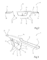
- Figure 2 shows a tool 17 for disassembling and assembling an inlet stage 6.
- Tool 17 comprises a reinforcement element 18, in particular a plate adapted to be coupled to inlet stage 6 to increase the stiffness of inlet stage 6, and a holding element 19, in particular a crossbar rigidly connected to plate 18.
- plate 18 has a substantially semicircular shape and is adapted to be coupled to one of inner half rings 11a, 11b of inlet stage 6.
- Plate 18 has a peripheral edge 21 provided with four holes 22 for the housing of screws (not shown) for the attachment of one of inner half rings 11a, 11b of inlet stage 6 and has a front face 23 and a back face 24.
- Crossbar 19 is adapted to be arranged in abutment against the ends of one of inner half rings 11a, 11b and of one of outer half rings 12a, 12b.
- Crossbar 19 has a central portion 26 which is rigidly connected to plate 18 and two end portions 27, each of which is provided with a hole 28 for housing a screw and a bolt provided with an eyelet coupled to a ring (not shown in the accompanying figures).
- Plate 18 is arranged substantially orthogonal with respect to cross bar 19.
- tool 17 comprises three support elements 29, in particular three support wings of support plate 18, which are connected to back face 24 of plate 18 and to crossbar 19 and are adapted to give greater structural stiffness to plate 18.
- Tool 17 is mainly used during the maintenance operations of a compressor 1 of a gas turbine unit.
- the maintenance method of compressor 1 substantially comprises disassembling inlet stage 6, performing the required maintenance and renewal operations of inlet stage 6 and reassembling inlet stage 6.
- the step of disassembling inlet stage 6 substantially comprises separating half shells 5a, 5b defining outer cylindrical casing 4, separating inner half rings 11a, 11b and separating outer half rings 12a, 12b, so that first half 14 of inlet stage 6 is housed in half shell 5a.
- the step of disassembling inlet stage 6 comprises removing half shell 5a of outer cylindrical casing 4, comprising first half 14 of inlet stage 6, and positioning it somewhere dedicated in a substantially vertical position.
- the step of disassembling inlet stage 6 comprises disassembling first half 14 of inlet stage 6 coupled to half shell 5a and subsequently disassembling second half 15 of inlet stage 6 coupled to half shell 5b.
- step of disassembling first half 14 of inlet stage 6 comprises:
- the step of disassembling second half 15 of inlet stage 6 comprises:
- the torque is applied by exerting a tractive force to an end portion 27 of crossbar 19, for instance by means of at least one tie-rod fixed to the ring of the nut connected to end portion 27, and pushing end portion 27 opposite to crossbar 19, for instance manually.
- first and second halves 14, 15 of inlet stage 6 are displaced in respective positions in which the maintenance and reconditioning operations are performed.
- the displacement of first and second halves 14, 15 of inlet stage 6 is performed by using tie-rods, connected to end portions 27 of crossbar 19 and to outer half ring 12a, 12b, and displaced by appropriate machines for lifting and displacing materials (for instance a bridge-crane).
- inlet stage 6 is reassembled.
- the method for assembling the inlet stage substantially comprises coupling inlet stage 6 to plate 18; and housing outer ring 8 of inlet stage 6 of compressor 1 in annular guide 13 of outer cylindrical casing 4.
- the method for assembling comprises:
- the torque is applied by exerting a tractive force to an end portion 27 of crossbar 19, for instance by means of at least one tie-rod fixed to the ring of the nut connected to end portion 27, and pushing end portion 27 opposite to crossbar 19, for instance manually.
Landscapes
- Engineering & Computer Science (AREA)
- Mechanical Engineering (AREA)
- General Engineering & Computer Science (AREA)
- Structures Of Non-Positive Displacement Pumps (AREA)
Abstract
A tool for assembling and disassembling an inlet stage (6) of a compressor (1) of a gas turbine unit is provided with a reinforcement element (18) adapted to be coupled to the inlet stage (6) to increase the stiffness of the inlet stage (6) and with a holding element (19) rigidly connected to the reinforcement element (18).
Description
- The present invention relates to a tool for assembling and disassembling an inlet stage of a compressor of a gas turbine unit, to a method for disassembling and to a method for assembling said stage.
- After a first life cycle, the electric power plants comprising gas turbine units are generally subjected to service and maintenance operations.
- During these operations the compressor must often be disassembled in order to carry out an inspection of the state of the parts of the compressor and, if necessary, perform maintenance or reconditioning operations of some parts of the compressor.
- The disassembly of the compressor and the subsequent assembly upon completion of the maintenance operations are particularly complex manoeuvres, during which there is a very high risk of damaging parts of the compressor.
- In particular, the most critical manoeuvres are the disassembly and the assembly of compressor inlet stage. The compressor inlet stage comprises an inner ring, an outer ring and an array of orientable vanes, more commonly designated as IGVs (Inlet Guide Vanes), which are arranged radially between the inner ring and the outer ring. The presence of orientable vanes considerably reduces the structural stiffness of the inlet stage with respect to the remaining stages of the compressor in which the vanes are fixed. Therefore, the handling of the compressor inlet stage is very difficult as the poor stiffness of the inlet stage increases the risk of compromising the structural integrity of the inlet stage itself. Moreover, the inlet stage of the compressor comprises fine handling mechanisms for the orientable vanes, which easily suffer damages during the assembly and disassembly manoeuvres.
- The known methods for disassembling and assembling the inlet stage of the compressor require the intervention of operators during all of the assembly and disassembly manoeuvres with a significant waste of time.
- It is an object of the present invention to provide a tool for disassembling and assembling an inlet stage of a compressor of a gas turbine unit allowing to simplify the disassembly and assembly operations of the inlet stage.
- According to this object, the present invention relates to a tool for assembling and disassembling an inlet stage of a compressor of a gas turbine unit; the inlet stage comprising an inner ring, defined by two coupled inner half-rings, an outer ring, defined by two coupled outer half rings, and an array of orientable vanes arranged radially between the inner ring and the outer ring; the tool being characterised by comprising a reinforcement element adapted to be coupled to the inlet stage in order to increase the stiffness of the inlet stage, and a holding element rigidly connected to the reinforcement element.
- It is a further object of the invention to provide a fast and cost-effective method for disassembling an inlet stage of a compressor of a gas turbine unit.
- According to this object, the present invention relates to a method for disassembling an inlet stage of a compressor of a gas turbine unit characterised by comprising the steps of:
- coupling at least one reinforcement element adapted to increase the stiffness of the inlet stage to the inlet stage; and removing the inlet stage.
- It is a further object of the invention to provide a fast and cost-effective method for assembling an inlet stage of a compressor of a gas turbine unit.
- According to this object, the present invention relates to a method for assembling an inlet stage of a compressor of a gas turbine unit; the inlet stage comprising an inner ring, an outer ring and an array of orientable vanes arranged radially between the inner ring and the outer ring; the method being characterized in that it comprises the steps of:
- coupling at least one reinforcement element adapted to increase the stiffness of the inlet stage to the inlet stage; and
- housing the outer ring of the inlet stage of the compressor in an annular guide of an outer cylindrical casing of the compressor defined by two coupled half shells.
- Further features and advantages of the present invention will be apparent from the following disclosure of a non-limitative embodiment thereof, with reference to the figures of the accompanying drawings, in which:
-
Figure 1 is a front view, with parts in section and parts removed for clarity, of a compressor of a gas turbine unit; -
Figure 2 is a front perspective view of a tool for assembling and disassembling an inlet stage of a compressor according to the present invention; -
figure 3 is a back perspective view of the tool offigure 2 ; -
Figure 4 is a perspective view, with parts in section and parts removed for clarity, of the tool offigure 2 in a first operative position; and -
Figure 5 is a perspective view, with parts in section and parts removed for clarity, of the tool offigure 2 in a second operative position. -
Figure 1 shows a compressor 1 of the multistage axial type of a gas turbine unit (not shown in the accompanying figures) which comprises ashaft 2, extending along a longitudinal axis A, an inner cylindrical casing 3, which extends about a portion ofshaft 2, and an outercylindrical casing 4, which extends aboutshaft 2 and is defined by twohalf shells - Compressor 1 comprises a plurality of stages (not shown in the accompanying figures) and an
inlet stage 6, which comprises aninner ring 7, anouter ring 8 and an array oforientable vanes 9, which are commonly designated as IGVs (Inlet Guide Vanes). -
Inner ring 7 is defined by twoinner half rings outer ring 8 is defined by twoouter half rings annular guide 13 of outercylindrical casing 4. In particular,outer half rings first portion 13a ofannular guide 13 defined inhalf shell 5a and in asecond portion 13b ofannular guide 13 defined inhalf shell 5b. -
Inlet stage 6 may therefore be separated into afirst half 14 and asecond half 15.First half 14 comprises aninner half ring 11a, anouter half ring 12a andorientable vanes 9 comprised betweeninner half ring 11a andouter half ring 12a.Second half 15 comprises aninner half ring 11b, anouter half ring 12b andorientable vanes 9 comprised betweeninner half ring 11b andouter half ring 12b. -
Figure 2 shows atool 17 for disassembling and assembling aninlet stage 6.Tool 17 comprises areinforcement element 18, in particular a plate adapted to be coupled toinlet stage 6 to increase the stiffness ofinlet stage 6, and aholding element 19, in particular a crossbar rigidly connected toplate 18. - In particular,
plate 18 has a substantially semicircular shape and is adapted to be coupled to one ofinner half rings inlet stage 6.Plate 18 has aperipheral edge 21 provided with fourholes 22 for the housing of screws (not shown) for the attachment of one ofinner half rings inlet stage 6 and has afront face 23 and aback face 24. - Crossbar 19 is adapted to be arranged in abutment against the ends of one of
inner half rings outer half rings - Crossbar 19 has a
central portion 26 which is rigidly connected toplate 18 and twoend portions 27, each of which is provided with ahole 28 for housing a screw and a bolt provided with an eyelet coupled to a ring (not shown in the accompanying figures). -
Plate 18 is arranged substantially orthogonal with respect tocross bar 19. - With reference to
figure 3 ,tool 17 comprises threesupport elements 29, in particular three support wings ofsupport plate 18, which are connected toback face 24 ofplate 18 and tocrossbar 19 and are adapted to give greater structural stiffness toplate 18. -
Tool 17 according to present invention is mainly used during the maintenance operations of a compressor 1 of a gas turbine unit. - The maintenance method of compressor 1 substantially comprises disassembling
inlet stage 6, performing the required maintenance and renewal operations ofinlet stage 6 and reassemblinginlet stage 6. - In particular, the step of disassembling
inlet stage 6 substantially comprises separatinghalf shells cylindrical casing 4, separatinginner half rings outer half rings first half 14 ofinlet stage 6 is housed inhalf shell 5a. Subsequently, the step of disassemblinginlet stage 6 comprises removinghalf shell 5a of outercylindrical casing 4, comprisingfirst half 14 ofinlet stage 6, and positioning it somewhere dedicated in a substantially vertical position. - At this point, the step of disassembling
inlet stage 6 comprises disassemblingfirst half 14 ofinlet stage 6 coupled tohalf shell 5a and subsequently disassemblingsecond half 15 ofinlet stage 6 coupled tohalf shell 5b. - In particular the step of disassembling
first half 14 ofinlet stage 6 comprises: -
coupling plate 18 oftool 17 to innerhalf ring 11a offirst half 14 of inlet stage 6 (seefigure 4 ); and - removing
first half 14 ofinlet stage 6 withplate 18 coupled, by applying a torque tocrossbar 19 to rotatetool 17 so as to extractouter half ring 12a offirst half 14 ofinlet stage 6 from respectivefirst portion 13a of annular guide 13 (seefigure 5 ). - The step of disassembling
second half 15 ofinlet stage 6 comprises: -
coupling plate 18 to innerhalf ring 11b ofsecond half 15 ofinlet stage 6; and - removing
second half 15 ofinlet stage 6 withplate 18 coupled, by applying a torque tocrossbar 19 to rotatetool 17 so as to extractouter half ring 12b ofsecond half 14 ofinlet stage 6 from respectivesecond portion 13b ofannular guide 13. - In particular, the torque is applied by exerting a tractive force to an
end portion 27 ofcrossbar 19, for instance by means of at least one tie-rod fixed to the ring of the nut connected toend portion 27, and pushingend portion 27 opposite to crossbar 19, for instance manually. - Once extracted, first and
second halves inlet stage 6 are displaced in respective positions in which the maintenance and reconditioning operations are performed. The displacement of first andsecond halves inlet stage 6 is performed by using tie-rods, connected toend portions 27 ofcrossbar 19 and toouter half ring - Once the maintenance operations are finished,
inlet stage 6 is reassembled. - The method for assembling the inlet stage substantially comprises
coupling inlet stage 6 toplate 18; and housingouter ring 8 ofinlet stage 6 of compressor 1 inannular guide 13 of outercylindrical casing 4. - In particular the method for assembling comprises:
- attaching
plate 18 to innerhalf ring 11a offirst half 14 ofinlet stage 6; - housing
outer half ring 12a offirst half 14 ofinlet stage 6 infirst portion 13a ofannular guide 13 by applying a torque tocrossbar 19 to rotatetool 17 so as to insertouter half ring 12a offirst half 14 ofinlet stage 6 in respectivefirst portion 13a ofannular guide 13 inhalf shell 5a; - attaching
plate 18 to innerhalf ring 11b ofsecond half 15 ofinlet stage 6; - housing
outer half ring 12b ofsecond half 15 ofinlet stage 6 by applying a torque tocrossbar 19 to rotatetool 17 so as to insertouter half ring 12b ofsecond half 15 ofinlet stage 6 in respectivesecond portion 13b ofannular guide 13. - Similarly to disassembling, the torque is applied by exerting a tractive force to an
end portion 27 ofcrossbar 19, for instance by means of at least one tie-rod fixed to the ring of the nut connected toend portion 27, and pushingend portion 27 opposite to crossbar 19, for instance manually. - It is finally apparent that modifications and variants may be made to
tool 17 for disassembling and assembling and to the methods for disassembling and assembling the inlet stage of a compressor disclosed herein, without departing from the scope of the appended claims.
Claims (20)
- A tool for assembling and disassembling an inlet stage (6) of a compressor (1) of a gas turbine unit; the inlet stage (6) comprising an inner ring (7), defined by two coupled inner half rings (11a, 11b), an outer ring (8), defined by two coupled outer half rings (12a, 12b), and an array of orientable vanes (9) arranged radially between the inner ring (7) and the outer ring (8); the tool (17) being characterised by comprising a reinforcement element (18) adapted to be coupled to the inlet stage (6) to increase the stiffness of the inlet stage (6), and a holding element (19) rigidly connected to the reinforcement element (18).
- The tool according to claim 1, characterised in that the reinforcement element (18) is a plate having a substantially semicircular shape that may be connected to one of the inner half rings (11a; 11b) of the inlet stage (6).
- The tool according to claim 1 or 2,
characterised in that the holding element (19) is a crossbar, which has a central portion (26) rigidly connected to the reinforcement element (18) and two end portions (27). - The tool according to claim 3, characterised in that the crossbar (19) is provided, at each end portion (27), with a hole (22) adapted to house a screw and a nut provided with an eyelet coupled to a ring for the connection to handling means.
- The tool according to claim 3 or 4,
characterised by comprising at least one support element (29) connected to the reinforcement element (18) and to the crossbar (19); the reinforcement element (18) being substantially orthogonal to the crossbar (19). - A method for disassembling an inlet stage (6) of a compressor (1) of a gas turbine unit characterised by comprising the steps of:coupling at least one reinforcement element (18) adapted to increase the stiffness of the inlet stage (6) to the inlet stage (6); andremoving the inlet stage (6).
- The method according to claim 6, characterised in that the inlet stage (6) comprises an inner ring (7), defined by two coupled inner half rings (11a, 11b), an outer ring (8), defined by two coupled outer half rings (12a, 12b), and an array of orientable vanes (9) radially arranged between the inner ring (7) and the outer ring (8); the outer ring (8) being housed in an annular guide (13) of an outer cylindrical casing (4) of the compressor (1), defined by two coupled half shells (5a, 5b); the method comprising the steps of separating the half shells (5a, 5b) defining the outer cylindrical casing (4), separating the inner half rings (11a, 11b) and separating the outer half rings (12a, 12b), so that a first half (14) of the inlet stage (6), comprising one of the inner half rings (11a) and one of the outer half rings (12a), is housed in a first one of the half shells (5a) with the respective outer half ring (12a) in a first portion (13a) of the annular guide (13) defined in the first half shell (5a), and a second half (15) of the inlet stage (6), comprising the other inner half ring (11b) and the other outer half ring (12b), is housed in a second one of the half shells (5b), with the respective outer half ring (12b) in a second portion (13b) of the annular guide (13) defined in the second half shell (5b).
- The method according to claim 7, characterised in that the step of coupling the reinforcement element (18) to the inlet stage (6) comprises the step of coupling the reinforcement element (18) to the first half (14) of the inlet stage (6) and in that the step of removing the inlet stage (6) comprises the step of removing the first half (14) of the inlet stage (6) with the reinforcement element (18) coupled to the first half (14) of the inlet stage (6).
- The method according to claim 8, characterised in that the step of coupling the reinforcement element (18) to the first half (14) of the inlet stage (6) comprises the step of attaching the reinforcement element (18) to the inner half ring (11a) of the first half (14) of the inlet stage (6).
- The method according to claim 8 or 9,
characterised in that the step of removing the first half (14) of the inlet stage (6) comprises applying a torque to the reinforcement element (18) to rotate the reinforcement element (18) so as to extract the outer half ring (12a) to the first half (14) of the inlet stage (6) from the respective first portion (13a) of annular guide (13). - The method according to one of claims 7 to 10, characterised in that the step of coupling the reinforcement element (18) to the inlet stage (6) comprises the step of coupling the reinforcement element (18) to the second half (15) of the inlet stage (6) and in that the step of removing the inlet stage (6) comprises the step of removing the second half (15) of the inlet stage (6) with the reinforcement element (18) coupled to the second half (15) of the inlet stage (6).
- The method according to claim 11, characterised in that the step of coupling the reinforcement element (18) to the second half (15) of the inlet stage (6) comprises the step of attaching the reinforcement element (18) to the inner half ring (11b) of the second half (15) of the inlet stage (6).
- The method according to claim 11 or 12,
characterised in that the step of removing the second half (15) of the inlet stage (6) comprises applying a torque to the reinforcement element (18) to rotate the reinforcement element (18) so as to extract the outer half ring (12b) to the second half (15) of the inlet stage (6) from the respective second portion (13b) of annular guide (13). - A method for assembling an inlet stage (6) of a compressor (1) of a gas turbine unit; the inlet stage (6) comprising an inner ring (7), an outer ring (8) and an array of orientable vanes (9) arranged radially between the inner ring (7) and the outer ring (8); the method being characterized by comprising the steps of:coupling at least one reinforcement element (18) adapted to increase the stiffness of the inlet stage (6) to the inlet stage (6); andhousing the outer ring (8) of the inlet stage (6) of the compressor (1) in an annular guide (13) of an outer cylindrical casing (4) of the compressor (1).
- The method according to claim 14, characterised in that the inner ring (7) is defined by two inner half rings (11a, 11b), the outer ring (8) is defined by two outer half rings (12a, 12b) and the outer cylindrical casing (4) is defined by two half shells (5a, 5b); and in that the step of coupling at least one reinforcement element (18) to the inlet stage (6) comprises the step of coupling the reinforcement element (18) to a first half (14) of the inlet stage (6), comprising one of the inner half rings (11a) and one of the outer half rings (12a), and in that the step of housing the outer ring (8) comprises housing the outer half ring (12a) of the first half (14) of the inlet stage (6) in a first portion (13a) of the annular guide (13) defined in the first half shell (5a).
- The method according to claim 15, characterised in that the step of coupling the reinforcement element (18) to the first half (14) of the inlet stage (6) comprises the step of attaching the reinforcement element (18) to the inner half ring (11a) of the first half (14) of the inlet stage (6).
- The method according to claim 15 or 16,
characterised in that the step of housing the outer half ring (12a) comprises the step of applying a torque to the reinforcement element (18) to rotate the reinforcement element (18) so as to insert the outer half ring (12a) of the first half (14) of the inlet stage (6) in the respective first portion (13a) of annular guide (13) defined in the second half shell (5b). - The method according to one of claims 14 to 17, characterised in that the inner ring (7) is defined by two inner half rings (11a, 11b), the outer ring (8) is defined by two outer half rings (12a, 12b) and the outer cylindrical casing (4) is defined by two half shells (5a, 5b); and in that the step of coupling the reinforcement element (18) to the inlet stage (6) comprises the step of coupling the reinforcement element (18) to a second half (15) of the inlet stage (6), comprising the other one of the inner half rings (11b) and the other one of the outer half rings (12b), and in that the step of housing the outer ring (8) comprises housing the outer half ring (12b) of the second half (15) of the inlet stage (6) in a second portion (13a) of the annular guide (13) defined in the second half shell (5b).
- The method according to claim 18, characterised in that the step of coupling the reinforcement element (18) to the second half (15) of the inlet stage (6) comprises the step of attaching the reinforcement element (18) to the inner half ring (11b) of the second half (15) of the inlet stage (6).
- The method according to claim 18 or 19,
characterised in that the step of housing the outer half ring (12b) of the second half (15) of the inlet stage (6) comprises the step of applying a torque to the reinforcement element (18) to rotate the reinforcement element (18) so as to insert the outer half ring (12b) of the second half (15) of the inlet stage (6) in the respective second portion (13b) of annular guide (13) defined in the second half shell (5b).
Applications Claiming Priority (1)
| Application Number | Priority Date | Filing Date | Title |
|---|---|---|---|
| ITMI20080540 ITMI20080540A1 (en) | 2008-03-28 | 2008-03-28 | TOOL FOR ASSEMBLY AND DISASSEMBLY OF AN ENTRY STAGE OF A COMPRESSOR OF A GAS TURBINE UNIT, DISASSEMBLY METHOD AND ASSEMBLY METHOD OF THIS STADIUM |
Publications (1)
| Publication Number | Publication Date |
|---|---|
| EP2105584A2 true EP2105584A2 (en) | 2009-09-30 |
Family
ID=40292995
Family Applications (1)
| Application Number | Title | Priority Date | Filing Date |
|---|---|---|---|
| EP20090156080 Withdrawn EP2105584A2 (en) | 2008-03-28 | 2009-03-24 | Tool for assembling and disassembling an inlet stage of a compressor of a gas turbine unit, method for disassembling and method for assembling said stage |
Country Status (2)
| Country | Link |
|---|---|
| EP (1) | EP2105584A2 (en) |
| IT (1) | ITMI20080540A1 (en) |
-
2008
- 2008-03-28 IT ITMI20080540 patent/ITMI20080540A1/en unknown
-
2009
- 2009-03-24 EP EP20090156080 patent/EP2105584A2/en not_active Withdrawn
Also Published As
| Publication number | Publication date |
|---|---|
| ITMI20080540A1 (en) | 2009-09-29 |
Similar Documents
| Publication | Publication Date | Title |
|---|---|---|
| EP1614856B1 (en) | Device for demounting of a turbine or compressor blade | |
| CN102232146B (en) | Wind turbine generator and maintenance method thereof | |
| US8056227B2 (en) | Turbine blade having material block and related method | |
| US6450763B1 (en) | Replaceable variable stator vane for gas turbines | |
| EP3023580A1 (en) | Gas turbine with plurality of tie rods and method of assembling the same | |
| KR101499406B1 (en) | Link mechanism, and variable stationary-blade driving device provided therewith | |
| CN104619954B (en) | Method for assembling or disassembling a rotor of an axially flowable turbomachine comprising a number of rotor components and such a rotor | |
| JP4315912B2 (en) | Machine stator and assembly and disassembly method | |
| US20190275575A1 (en) | Hydraulic extrusion tool with integrated induction device | |
| CN104246144B (en) | For dismantling method and the heater of turbofan engine | |
| US20150010395A1 (en) | Stator Blade Sector for an Axial Turbomachine with a Dual Means of Fixing | |
| US11215079B2 (en) | Turbomachine and method for disassembling such a turbomachine | |
| US9885386B2 (en) | Bearing assembly | |
| EP2105584A2 (en) | Tool for assembling and disassembling an inlet stage of a compressor of a gas turbine unit, method for disassembling and method for assembling said stage | |
| EP2033741A2 (en) | Tool for removing and assembling | |
| CN111511505B (en) | Tool for removing annular components of a turbine engine | |
| JP6678188B2 (en) | Assembling / disassembling apparatus for flanged mechanical device and assembling / disassembling method for flanged mechanical device | |
| JP2014037827A (en) | Balance weight installation system and related method | |
| RU71767U1 (en) | KEY FOR ASSEMBLY AND DISASSEMBLY OF HYDRAULIC BOTTOM ENGINES | |
| US10471553B2 (en) | Tool for extracting a metal piece | |
| CN222874486U (en) | Hydraulic Cartridge Valve Removal Tool | |
| JP5529059B2 (en) | Turbine blade connecting pin punching apparatus and turbine blade connecting pin punching method | |
| CN113374711B (en) | Axial flow fan | |
| EP3620258B1 (en) | Method for repairing a rotor of a multi-stage axial compressor of a gas turbine | |
| WO2025239221A1 (en) | Method for disassembling and assembling rotary machine, and insertion/removal jig for positioning pin |
Legal Events
| Date | Code | Title | Description |
|---|---|---|---|
| PUAI | Public reference made under article 153(3) epc to a published international application that has entered the european phase |
Free format text: ORIGINAL CODE: 0009012 |
|
| AK | Designated contracting states |
Kind code of ref document: A2 Designated state(s): AT BE BG CH CY CZ DE DK EE ES FI FR GB GR HR HU IE IS IT LI LT LU LV MC MK MT NL NO PL PT RO SE SI SK TR |
|
| AX | Request for extension of the european patent |
Extension state: AL BA RS |
|
| STAA | Information on the status of an ep patent application or granted ep patent |
Free format text: STATUS: THE APPLICATION IS DEEMED TO BE WITHDRAWN |
|
| 18D | Application deemed to be withdrawn |
Effective date: 20121002 |