EP2105537A1 - Panel and process for producing the same - Google Patents
Panel and process for producing the same Download PDFInfo
- Publication number
- EP2105537A1 EP2105537A1 EP07767548A EP07767548A EP2105537A1 EP 2105537 A1 EP2105537 A1 EP 2105537A1 EP 07767548 A EP07767548 A EP 07767548A EP 07767548 A EP07767548 A EP 07767548A EP 2105537 A1 EP2105537 A1 EP 2105537A1
- Authority
- EP
- European Patent Office
- Prior art keywords
- thin plate
- outer thin
- edge part
- foam material
- panel
- Prior art date
- Legal status (The legal status is an assumption and is not a legal conclusion. Google has not performed a legal analysis and makes no representation as to the accuracy of the status listed.)
- Granted
Links
Images


Classifications
-
- E—FIXED CONSTRUCTIONS
- E02—HYDRAULIC ENGINEERING; FOUNDATIONS; SOIL SHIFTING
- E02F—DREDGING; SOIL-SHIFTING
- E02F9/00—Component parts of dredgers or soil-shifting machines, not restricted to one of the kinds covered by groups E02F3/00 - E02F7/00
- E02F9/08—Superstructures; Supports for superstructures
- E02F9/0858—Arrangement of component parts installed on superstructures not otherwise provided for, e.g. electric components, fenders, air-conditioning units
- E02F9/0891—Lids or bonnets or doors or details thereof
-
- B—PERFORMING OPERATIONS; TRANSPORTING
- B62—LAND VEHICLES FOR TRAVELLING OTHERWISE THAN ON RAILS
- B62D—MOTOR VEHICLES; TRAILERS
- B62D25/00—Superstructure or monocoque structure sub-units; Parts or details thereof not otherwise provided for
- B62D25/08—Front or rear portions
- B62D25/10—Bonnets or lids, e.g. for trucks, tractors, busses, work vehicles
-
- B—PERFORMING OPERATIONS; TRANSPORTING
- B62—LAND VEHICLES FOR TRAVELLING OTHERWISE THAN ON RAILS
- B62D—MOTOR VEHICLES; TRAILERS
- B62D29/00—Superstructures, understructures, or sub-units thereof, characterised by the material thereof
- B62D29/001—Superstructures, understructures, or sub-units thereof, characterised by the material thereof characterised by combining metal and synthetic material
- B62D29/002—Superstructures, understructures, or sub-units thereof, characterised by the material thereof characterised by combining metal and synthetic material a foamable synthetic material or metal being added in situ
-
- Y—GENERAL TAGGING OF NEW TECHNOLOGICAL DEVELOPMENTS; GENERAL TAGGING OF CROSS-SECTIONAL TECHNOLOGIES SPANNING OVER SEVERAL SECTIONS OF THE IPC; TECHNICAL SUBJECTS COVERED BY FORMER USPC CROSS-REFERENCE ART COLLECTIONS [XRACs] AND DIGESTS
- Y10—TECHNICAL SUBJECTS COVERED BY FORMER USPC
- Y10T—TECHNICAL SUBJECTS COVERED BY FORMER US CLASSIFICATION
- Y10T428/00—Stock material or miscellaneous articles
- Y10T428/13—Hollow or container type article [e.g., tube, vase, etc.]
- Y10T428/1352—Polymer or resin containing [i.e., natural or synthetic]
- Y10T428/1376—Foam or porous material containing
-
- Y—GENERAL TAGGING OF NEW TECHNOLOGICAL DEVELOPMENTS; GENERAL TAGGING OF CROSS-SECTIONAL TECHNOLOGIES SPANNING OVER SEVERAL SECTIONS OF THE IPC; TECHNICAL SUBJECTS COVERED BY FORMER USPC CROSS-REFERENCE ART COLLECTIONS [XRACs] AND DIGESTS
- Y10—TECHNICAL SUBJECTS COVERED BY FORMER USPC
- Y10T—TECHNICAL SUBJECTS COVERED BY FORMER US CLASSIFICATION
- Y10T428/00—Stock material or miscellaneous articles
- Y10T428/24—Structurally defined web or sheet [e.g., overall dimension, etc.]
- Y10T428/24479—Structurally defined web or sheet [e.g., overall dimension, etc.] including variation in thickness
- Y10T428/24496—Foamed or cellular component
-
- Y—GENERAL TAGGING OF NEW TECHNOLOGICAL DEVELOPMENTS; GENERAL TAGGING OF CROSS-SECTIONAL TECHNOLOGIES SPANNING OVER SEVERAL SECTIONS OF THE IPC; TECHNICAL SUBJECTS COVERED BY FORMER USPC CROSS-REFERENCE ART COLLECTIONS [XRACs] AND DIGESTS
- Y10—TECHNICAL SUBJECTS COVERED BY FORMER USPC
- Y10T—TECHNICAL SUBJECTS COVERED BY FORMER US CLASSIFICATION
- Y10T428/00—Stock material or miscellaneous articles
- Y10T428/24—Structurally defined web or sheet [e.g., overall dimension, etc.]
- Y10T428/24628—Nonplanar uniform thickness material
- Y10T428/24661—Forming, or cooperating to form cells
-
- Y—GENERAL TAGGING OF NEW TECHNOLOGICAL DEVELOPMENTS; GENERAL TAGGING OF CROSS-SECTIONAL TECHNOLOGIES SPANNING OVER SEVERAL SECTIONS OF THE IPC; TECHNICAL SUBJECTS COVERED BY FORMER USPC CROSS-REFERENCE ART COLLECTIONS [XRACs] AND DIGESTS
- Y10—TECHNICAL SUBJECTS COVERED BY FORMER USPC
- Y10T—TECHNICAL SUBJECTS COVERED BY FORMER US CLASSIFICATION
- Y10T428/00—Stock material or miscellaneous articles
- Y10T428/249921—Web or sheet containing structurally defined element or component
- Y10T428/249953—Composite having voids in a component [e.g., porous, cellular, etc.]
-
- Y—GENERAL TAGGING OF NEW TECHNOLOGICAL DEVELOPMENTS; GENERAL TAGGING OF CROSS-SECTIONAL TECHNOLOGIES SPANNING OVER SEVERAL SECTIONS OF THE IPC; TECHNICAL SUBJECTS COVERED BY FORMER USPC CROSS-REFERENCE ART COLLECTIONS [XRACs] AND DIGESTS
- Y10—TECHNICAL SUBJECTS COVERED BY FORMER USPC
- Y10T—TECHNICAL SUBJECTS COVERED BY FORMER US CLASSIFICATION
- Y10T428/00—Stock material or miscellaneous articles
- Y10T428/249921—Web or sheet containing structurally defined element or component
- Y10T428/249953—Composite having voids in a component [e.g., porous, cellular, etc.]
- Y10T428/24996—With internal element bridging layers, nonplanar interface between layers, or intermediate layer of commingled adjacent foam layers
Definitions
- the present invention relates to a panel provided with a foam material and a method for manufacturing the same.
- Patent Reference 1 the cover body structure becomes heavy in order to obtain sufficient strength using the inner reinforcing plate, and welding traces tend to appear on the outside. Also, neither sound insulating performance nor sound absorbing performance is sufficient.
- the lining member such as the sound absorbing material is visible from the outside when opening the engine cover, creating an unattractive appearance and insufficient strength.
- the present invention has been made in consideration of the above-mentioned problems, and it is an object of the present invention to provide a panel capable of obtaining sufficient strength, weight reduction and sound absorbing performance, and a method for manufacturing the panel.
- the invention according to claim 1 provides a panel including:
- the invention according to claim 2 provides the panel according to claim 1, wherein the inner thin plate is bonded to the outer thin plate.
- the invention according to claim 3 provides the panel according to claim 1 or 2, wherein the outer thin plate has a turned-up edge part which is a turned-up perimetrical edge part crimped to and bonded to the inner thin plate.
- the invention according to claim 4 provides the panel according to any of claims 1 to 3, wherein a plurality of foam materials are arranged in one space.
- the invention according to claim 5 provides the panel according to any of claims 1 to 4, further including:
- the invention according to claim 6 provides a method for manufacturing a panel including the steps of:
- the invention according to claim 7 provides the method for manufacturing the panel according to claim 6, further including the steps of:
- the invention according to claim 8 provides the method for manufacturing the panel according to claim 6 or 7, further including the steps of:
- the invention according to claim 9 provides the method for manufacturing the panel according to any of claims 6 to 8, further including the steps of:
- a three-layer structure having the outer thin plate, the inner thin plate and the foam material filled in the space of the inner thin plate can provide sufficient strength and weight reduction and can provide sound absorbing performance by the foam material.
- the inner thin plate since the inner thin plate is bonded to the outer thin plate, the inner thin plate can be fixed more easily than welding, and the exposure of welding traces having a poor appearance on the outside can be prevented or reduced.
- the turned-up edge part formed by turning up the perimetrical edge part of the outer thin plate is crimped to and bonded to the inner thin plate, sufficient bonding strength between the outer thin plate and the inner thin plate can be secured by crimping strength and adhesive strength, and the sealing performance of a bonded part can be secured.
- the economical foaming shape corresponding to the shape of the space can be obtained by the plurality of foam materials.
- the fitting strength required for the hinge can be secured by welding the hinge to the end edge part of the outer thin plate via the fitting base member.
- the non-foam material of the foamable filler provided on the outer thin plate is foamed by the baking coating heating device to fill the foam material in the space of the inner thin plate, the non-foam material can be efficiently foamed in the baking coating. Thereby, the manufacturing efficiency can be enhanced and the baking coating heating device can be efficiently operated.
- thermosetting adhesive can be efficiently cured upon baking coating by the baking coating heating device, and the non-foam material can be efficiently foamed. Thereby, the manufacturing efficiency can be enhanced, and the baking coating heating device can be efficiently operated.
- air can be removed when the non-foam material of the foamable filler is foamed from the non-applied part of the adhesive by partially omitting the application of the adhesive when the adhesive is applied onto the perimetrical edge part of the outer thin plate, and a smooth foaming operation can be secured.
- the outer hole having any shape can be easily opened in the outer thin plate in the inner hole by laser processing by drilling the inner hole in the inner thin plate.
- a hydraulic backhoe 10 which is an operating machine, includes a lower travelling body 11 and an upper turning body 12 turnably provided on the lower travelling body 11.
- the engine 15 is covered with an engine hood 16, and the air filter and the radiator are covered with double swinging side door panels (hereinafter, simply referred to as panel) 17 and 18.
- Fig. 5 shows the air filter side panel 17.
- Fig. 6 shows the radiator side panel 18.
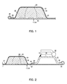
- Fig. 1 shows a partially expanded view of the panels 17 and 18.
- Each of the panels 17 and 18 is provided with an outer thin plate 21, an inner thin plate 23 fixed to the inner surface of the outer thin plate 21 and forming a space 22, and a foam material 24 filled in the space 22.
- the foam material 24 is preferably a highly foamable rubber sound absorbing material having a volume expansion coefficient of about 20 times.
- a perimetrical side part 25 and a perimetrical edge part 26 for forming the space 22, and a concave part 27 for enhancing the strength of a panel are drawn to the side of the outer thin plate 21.
- the bottom faces of the perimetrical edge part 26 and concave part 27 of the inner thin plate 23 are bonded to the outer thin plate 21 using a thermosetting adhesive.
- the perimetrical side part 25, perimetrical edge part 26 and concave part 27 projected to the side of the outer thin plate 21 are formed in the inner thin plate 23 by a drawing process.
- the space 22 is formed between the perimetrical side part 25 and the concave part 27 by bonding the bottom faces of the perimetrical edge part 26 and concave part 27 to the outer thin plate 21.
- the concave part 27 bonded to the outer thin plate 21 can enhance the strength of the panel and reduce the volume of the space 22 between the outer thin plate 21 and the inner thin plate 23 to reduce the amount of the required foam material 24.
- a turned-up edge part 28 formed by turning up the perimetrical edge part in the outer thin plate 21.
- the turned-up edge part 28 is crimped to the perimetrical edge part 26 of the inner thin plate 23, and is bonded by a thermosetting adhesive.
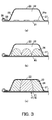
- a thick plate-like fitting base member 31 is fixed to the inner surface of the end edge part of the outer thin plate 21 by a thermosetting adhesive.
- a fitting plate 33 of one side of a hinge 32 is welded to the fitting base member 31. That is, the strength of the circumference of the hinge 32 is mostly required, and must be reinforced, so that one leg part 34 and the other leg part 35 of the fitting base member 31 are bonded along the hinge fitting edge part of the outer thin plate 21, and the fitting plate 33 of the hinge 32 is welded to a plane-like fitting face part 36.
- the turned-up edge part 28 formed by turning up a side end edge part of the outer thin plate 21 is crimped to one leg part 34 of the fitting base member 31, and bonded by a thermosetting adhesive.
- the perimetrical edge part 26 of the inner thin plate 23 is stacked on the other leg part 35 of the fitting base member 31, and is bonded by a thermosetting adhesive.
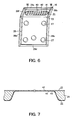
- non-foam materials 24a of the foamable filler are provided on the outer thin plate 21.
- the inner thin plate 23 forming the space 22 corresponding to the non-foam materials 24a is fixed to the outer thin plate 21.
- a thermosetting adhesive is supplied between contact surfaces of the outer thin plate 21 and inner thin plate 23.
- the non-foam materials 24a are stuck on the outer thin plate 21 so that a plurality of rubber sound absorbing materials are arranged at a proper interval in one space 22.
- the adhesive is cured by a baking coating heating device. Furthermore, as shown in Figs. 3(b) and 3(c) , the non-foam materials 24a are foamed by the baking coating heating device to fill the foam materials 24 in the space 22. Coating materials previously sprayed on the outer thin plate 21 and the inner thin plate 23 are baked by the baking coating heating device.
- thermosetting adhesive 38 is applied onto three perimetrical edge parts 28b, 28c, 28d, 28e and 28f of a right and left side edges and lower side edge among perimetrical edge parts 28a, 28b, 28c, 28d, 28e and 28f of the outer thin plate 21.
- the entire perimetrical edge parts 28a to 28f of the outer thin plate 21 are turned-up without applying the thermosetting adhesive 38 onto the perimetrical edge part 28a of the upper side edge, and the perimetrical edge parts 28a to 28f are fixed to the perimetrical edge part of the inner thin plate 23.
- the adhesive 38 may be intermittently applied in the form of perforations over the entire perimetrical edge part of the outer thin plate 21, or the adhesive 38 may be partially and intentionally removed. In short, when the adhesive 38 is applied onto the perimetrical edge part of the outer thin plate 21, the application of the adhesive 38 is partially omitted. On the other hand, the entire perimetrical edge part of the outer thin plate 21 is turned-up.
- the panel 18 shown in Figs. 6 and 7 is also similarly bent and bonded.
- two metal plates cannot be simultaneously laser-processed when forming a hole in the panel 18 prepared by stacking two metal plates.
- an inner hole 41 is drilled in the inner thin plate 23, and, a plurality of outer holes 42 are laser-processed and drilled in the outer thin plate 21 in the inner hole 41.
- Fig. 1 sufficient strength and weight reduction can be obtained by a three-layer structure of the outer thin plate 21, inner thin plate 23 and foam material 24 filled in the space 22 of the inner thin plate 23. That is, the foam material 24 is filled in the space 22 between the outer thin plate 21 and the inner thin plate 23, and they are wholly integrated. Thereby, the strength shortage of each of the outer thin plate 21 and inner thin plate 23 is compensated, and the strength can be enhanced as a whole.
- the sound absorbing performance can be obtained by the foam material 24, and the sound absorbing material bonded to the inner surface of the side door panel of the conventional engine cover can be removed.
- the inner thin plate 23 is bonded to the outer thin plate 21, the inner thin plate 23 is fixed more easily than welding, and the exposure of welding traces having a poor appearance on the outside can be prevented or reduced.
- the turned-up edge part 28 formed by turning up the perimetrical edge part of the outer thin plate 21 is crimped to and bonded to the perimetrical edge part 26 of the inner thin plate 23
- sufficient bond strength between the outer thin plate 21 and the inner thin plate 23 can be secured by crimping strength and adhesive strength, and the sealing performance of a bonded part can be secured.
- the economical foaming shape corresponding to the shape of the space 22 can be obtained by the plurality of foam materials 24.
- the fitting strength required for the hinge 32 can be secured by welding the hinge 32 to the end edge part of the outer thin plate 21 via the fitting base member 31.
- the non-foam material 24a of the foamable filler set on the outer thin plate 21 is foamed by the baking coating heating device to fill the foam material 24 in the space 22 of the inner thin plate 23, the non-foam material 24a can be efficiently foamed in the baking coating. Thereby, the manufacturing efficiency can be enhanced, and the baking coating heating device can be efficiently operated.
- thermosetting adhesive can be efficiently cured upon baking coating by the baking coating heating device, and the non-foam material 24a can be efficiently foamed. Thereby, the manufacturing efficiency can be enhanced, and the baking coating heating device can be efficiently operated.
- air can be removed when the non-foam material 24a of the foamable filler is foamed from the non-applied part of the adhesive 38 by intermittently applying the adhesive 38, and partially and intentionally removing the adhesive 38 to partially omit the application of the adhesive 38 when the adhesive 38 is applied onto the perimetrical edge part of the outer thin plate 21. Therefore, a smooth foaming operation can be secured, and the generation of problems of thin plate burst or the like in complete sealing can be prevented.
- the outer hole 42 having any shape can be easily opened in the outer thin plate 21 in the inner hole 41 by laser processing by drilling the inner hole 41 in the inner thin plate 23.
- a thick sheet metal having a thickness of 1.6 mm is further reinforced.
- the outer thin plate 21 a thin sheet metal having a thickness of 0.8 to 1.2 mm is used, and as the inner thin plate 23, a thin sheet metal having a thickness of about 0.35 to 0.6 mm is used.
- the thin plates 21 and 23 are laminated using an adhesive.
- the thin plates 21 and 23 are sealed by the perimetrical edge part 28 formed by turning up the perimetrical edge part of the outer thin plate 21.
- the non-foam material 24a of a foamable rubber sound absorbing material is laminated on the inner surface of the outer thin plate 21 facing the space 22 between the thin plates 21 and 23 before laminating them.
- This non-foam material 24a is foamed in a heat process in baking the coating so that the material is filled in a part or all of the space 22. Since the foam material 24 has reinforcing effect and sound absorbing performance, even a large-sized panel can suppress the weight to attain weight reduction and can enhance sound insulating performance and strength.
- the panel can strengthen the rigidity of a door, can substantially realize a reduction in noise of a standard door, and has excellent appearance.
- the present invention can be used for an opening/closing door panel, a non-opening/closing fixed panel, and a method for manufacturing the panels.
Landscapes
- Engineering & Computer Science (AREA)
- Structural Engineering (AREA)
- Combustion & Propulsion (AREA)
- Transportation (AREA)
- Mechanical Engineering (AREA)
- Chemical & Material Sciences (AREA)
- Civil Engineering (AREA)
- Mining & Mineral Resources (AREA)
- Architecture (AREA)
- General Engineering & Computer Science (AREA)
- Component Parts Of Construction Machinery (AREA)
- Soundproofing, Sound Blocking, And Sound Damping (AREA)
- Panels For Use In Building Construction (AREA)
- Diaphragms For Electromechanical Transducers (AREA)
- Laminated Bodies (AREA)
- Body Structure For Vehicles (AREA)
Abstract
Description
- The present invention relates to a panel provided with a foam material and a method for manufacturing the same.
- There has been a cover body structure obtained by welding an inner reinforcing plate having a concave part to an outer panel of construction machinery (for example, see Patent Reference 1).
- There has been an engine cover having a sound insulating material or a sound absorbing material as a lining member attached to the inner side of a cover body in construction machinery (for example, see Patent Reference 2).
- Patent Reference 1: Japanese Patent Application Laid-Open No.
09-228412 Fig. 7 ) - Patent Reference 2: Japanese patent Publication No.
3457804 Fig. 1 ) - In Patent Reference 1, the cover body structure becomes heavy in order to obtain sufficient strength using the inner reinforcing plate, and welding traces tend to appear on the outside. Also, neither sound insulating performance nor sound absorbing performance is sufficient.
- In Patent Document 2, the lining member such as the sound absorbing material is visible from the outside when opening the engine cover, creating an unattractive appearance and insufficient strength.
- The present invention has been made in consideration of the above-mentioned problems, and it is an object of the present invention to provide a panel capable of obtaining sufficient strength, weight reduction and sound absorbing performance, and a method for manufacturing the panel.
- The invention according to claim 1 provides a panel including:
- an outer thin plate;
- an inner thin plate fixed to an inner surface of the outer thin plate and forming a space; and
- a foam material filled in the space.
- The invention according to claim 2 provides the panel according to claim 1, wherein the inner thin plate is bonded to the outer thin plate.
- The invention according to claim 3 provides the panel according to claim 1 or 2, wherein the outer thin plate has a turned-up edge part which is a turned-up perimetrical edge part crimped to and bonded to the inner thin plate.
- The invention according to claim 4 provides the panel according to any of claims 1 to 3, wherein a plurality of foam materials are arranged in one space.
- The invention according to claim 5 provides the panel according to any of claims 1 to 4, further including:
- a fitting base member fixed to an inner surface of an end edge part of the outer thin plate; and
- a hinge welded to the fitting base member.
- The invention according to claim 6 provides a method for manufacturing a panel including the steps of:
- providing a non-foam material of a foamable filler on an outer thin plate;
- fixing an inner thin plate forming a space corresponding to the non-foam material to the outer thin plate;
- foaming the non-foam material by a baking coating heating device to fill the foam material in the space; and
- finishing at least the baking coating of the outer thin plate by the baking coating heating device.
- The invention according to claim 7 provides the method for manufacturing the panel according to claim 6, further including the steps of:
- supplying a thermosetting adhesive between the outer thin plate and the inner thin plate; and
- curing the adhesive by the baking coating heating device.
- The invention according to claim 8 provides the method for manufacturing the panel according to claim 6 or 7, further including the steps of:
- partially omitting the application of an adhesive when applying the adhesive onto a perimetrical edge part of the outer thin plate; and
- turning up the entire perimetrical edge part of the outer thin plate and fixing the perimetrical edge part to the perimetrical edge part of the inner thin plate.
- The invention according to claim 9 provides the method for manufacturing the panel according to any of claims 6 to 8, further including the steps of:
- drilling an inner hole in the inner thin plate; and
- laser processing an outer hole to the outer thin plate in the inner hole.
- According to the invention of claim 1, a three-layer structure having the outer thin plate, the inner thin plate and the foam material filled in the space of the inner thin plate can provide sufficient strength and weight reduction and can provide sound absorbing performance by the foam material.
- According to the invention of claim 2, since the inner thin plate is bonded to the outer thin plate, the inner thin plate can be fixed more easily than welding, and the exposure of welding traces having a poor appearance on the outside can be prevented or reduced.
- According to the invention of claim 3, since the turned-up edge part formed by turning up the perimetrical edge part of the outer thin plate is crimped to and bonded to the inner thin plate, sufficient bonding strength between the outer thin plate and the inner thin plate can be secured by crimping strength and adhesive strength, and the sealing performance of a bonded part can be secured.
- According to the invention of claim 4, the economical foaming shape corresponding to the shape of the space can be obtained by the plurality of foam materials.
- According to the invention of claim 5, the fitting strength required for the hinge can be secured by welding the hinge to the end edge part of the outer thin plate via the fitting base member.
- According to the invention of claim 6, since the non-foam material of the foamable filler provided on the outer thin plate is foamed by the baking coating heating device to fill the foam material in the space of the inner thin plate, the non-foam material can be efficiently foamed in the baking coating. Thereby, the manufacturing efficiency can be enhanced and the baking coating heating device can be efficiently operated.
- According to the invention of claim 7, the thermosetting adhesive can be efficiently cured upon baking coating by the baking coating heating device, and the non-foam material can be efficiently foamed. Thereby, the manufacturing efficiency can be enhanced, and the baking coating heating device can be efficiently operated.
- According to the invention of claim 8, air can be removed when the non-foam material of the foamable filler is foamed from the non-applied part of the adhesive by partially omitting the application of the adhesive when the adhesive is applied onto the perimetrical edge part of the outer thin plate, and a smooth foaming operation can be secured.
- According to the invention of claim 9, the outer hole having any shape can be easily opened in the outer thin plate in the inner hole by laser processing by drilling the inner hole in the inner thin plate.
-
-
Fig. 1 is a sectional view showing an embodiment of a panel according to the present invention; -
Fig. 2 is a sectional view of a hinge fitting part of the panel; -
Fig. 3 is a sectional view showing an example of a method for manufacturing the panel; Fig. (a) shows a state where a non-foam material is provided on an outer thin plate; Fig. (b) shows a state where a non-foam material is foaming; Fig. (c) shows a state where the foam formation of a foam material is completed; -
Fig. 4 is a perspective view of a hydraulic backhoe using the panel; -
Fig. 5 is a perspective view showing an assembly example of an outer thin plate and inner thin plate which constitute the panel; Fig. (a) shows a disassembly state thereof; Fig. (b) shows an assembly completion state thereof; -
Fig. 6 is a perspective view showing a hole processing example of the panel; and -
Fig. 7 is a cross section along the line VII-VII of Fig. - 6.
-
- 17, 18: panel
- 21: outer thin plate
- 22: space
- 23: inner thin plate
- 24: foam material
- 24a: non-foam material
- 28: turned-up edge part
- 28a to 28f: perimetrical edge part
- 31: fitting base member
- 32: hinge
- 38: adhesive
- 41: inner hole
- 42: outer hole
- Hereinafter, the present invention will be described in detail with reference to an embodiment shown in
Figs. 1 to 7 . - As shown in
Fig. 4 , ahydraulic backhoe 10, which is an operating machine, includes a lower travellingbody 11 and anupper turning body 12 turnably provided on the lower travellingbody 11. On theupper turning body 12, there is mounted acab 13, a workingdevice 14, anengine 15, and an air filter and a radiator which are related to theengine 15, or the like. Theengine 15 is covered with anengine hood 16, and the air filter and the radiator are covered with double swinging side door panels (hereinafter, simply referred to as panel) 17 and 18.Fig. 5 shows the airfilter side panel 17.Fig. 6 shows theradiator side panel 18. -
Fig. 1 shows a partially expanded view of thepanels panels thin plate 21, an innerthin plate 23 fixed to the inner surface of the outerthin plate 21 and forming aspace 22, and afoam material 24 filled in thespace 22. Thefoam material 24 is preferably a highly foamable rubber sound absorbing material having a volume expansion coefficient of about 20 times. - In the inner
thin plate 23, aperimetrical side part 25 and aperimetrical edge part 26 for forming thespace 22, and aconcave part 27 for enhancing the strength of a panel are drawn to the side of the outerthin plate 21. The bottom faces of theperimetrical edge part 26 andconcave part 27 of the innerthin plate 23 are bonded to the outerthin plate 21 using a thermosetting adhesive. - That is, the
perimetrical side part 25,perimetrical edge part 26 andconcave part 27 projected to the side of the outerthin plate 21 are formed in the innerthin plate 23 by a drawing process. Thereby, thespace 22 is formed between theperimetrical side part 25 and theconcave part 27 by bonding the bottom faces of theperimetrical edge part 26 andconcave part 27 to the outerthin plate 21. - The
concave part 27 bonded to the outerthin plate 21 can enhance the strength of the panel and reduce the volume of thespace 22 between the outerthin plate 21 and the innerthin plate 23 to reduce the amount of the requiredfoam material 24. - There is provided a turned-up
edge part 28 formed by turning up the perimetrical edge part in the outerthin plate 21. The turned-upedge part 28 is crimped to theperimetrical edge part 26 of the innerthin plate 23, and is bonded by a thermosetting adhesive. - As shown in
Fig. 2 , referring to thepanels fitting base member 31 is fixed to the inner surface of the end edge part of the outerthin plate 21 by a thermosetting adhesive. Afitting plate 33 of one side of a hinge 32 is welded to thefitting base member 31. That is, the strength of the circumference of the hinge 32 is mostly required, and must be reinforced, so that oneleg part 34 and theother leg part 35 of thefitting base member 31 are bonded along the hinge fitting edge part of the outerthin plate 21, and thefitting plate 33 of the hinge 32 is welded to a plane-like fitting facepart 36. The turned-upedge part 28 formed by turning up a side end edge part of the outerthin plate 21 is crimped to oneleg part 34 of thefitting base member 31, and bonded by a thermosetting adhesive. Theperimetrical edge part 26 of the innerthin plate 23 is stacked on theother leg part 35 of thefitting base member 31, and is bonded by a thermosetting adhesive. - Next, as shown in
Fig. 3(a) , referring to a method for manufacturing thepanels non-foam materials 24a of the foamable filler are provided on the outerthin plate 21. The innerthin plate 23 forming thespace 22 corresponding to thenon-foam materials 24a is fixed to the outerthin plate 21. At this time, a thermosetting adhesive is supplied between contact surfaces of the outerthin plate 21 and innerthin plate 23. Thenon-foam materials 24a are stuck on the outerthin plate 21 so that a plurality of rubber sound absorbing materials are arranged at a proper interval in onespace 22. - The adhesive is cured by a baking coating heating device. Furthermore, as shown in
Figs. 3(b) and 3(c) , thenon-foam materials 24a are foamed by the baking coating heating device to fill thefoam materials 24 in thespace 22. Coating materials previously sprayed on the outerthin plate 21 and the innerthin plate 23 are baked by the baking coating heating device. - For example, it is necessary to heat the adhesive at 150°C for 5 minutes in order to cure the adhesive; it is necessary to heat the
foam material 24 at 180°C for 20 minutes in order to complete the foam formation of thefoam material 24; and baking heating at 200°C for 20 minutes is required in order to complete the baking coating. Thereby, all the heatings can be performed by using the existing baking coating heating device. - In the manufacture of the
panel 17 shown inFig. 5(a) , athermosetting adhesive 38 is applied onto threeperimetrical edge parts perimetrical edge parts thin plate 21. As shown inFig. 5(b) , the entireperimetrical edge parts 28a to 28f of the outerthin plate 21 are turned-up without applying the thermosetting adhesive 38 onto theperimetrical edge part 28a of the upper side edge, and theperimetrical edge parts 28a to 28f are fixed to the perimetrical edge part of the innerthin plate 23. - That is, three side edges of the right and left side edges and lower side edge of the outer
thin plate 21 are bent and bonded. However, only the upper side edge is bent, and is not bonded. Alternatively, the adhesive 38 may be intermittently applied in the form of perforations over the entire perimetrical edge part of the outerthin plate 21, or the adhesive 38 may be partially and intentionally removed. In short, when the adhesive 38 is applied onto the perimetrical edge part of the outerthin plate 21, the application of the adhesive 38 is partially omitted. On the other hand, the entire perimetrical edge part of the outerthin plate 21 is turned-up. - The
panel 18 shown inFigs. 6 and 7 is also similarly bent and bonded. However, two metal plates cannot be simultaneously laser-processed when forming a hole in thepanel 18 prepared by stacking two metal plates. Thereby, aninner hole 41 is drilled in the innerthin plate 23, and, a plurality ofouter holes 42 are laser-processed and drilled in the outerthin plate 21 in theinner hole 41. - That is, it is technically difficult to form a hole in two layers of the outer
thin plate 21 and innerthin plate 23 simultaneously by laser processing. Thereby, when the hole is formed in such a two-layer panel, theinner hole 41 is previously formed in aconcave part 43 of the innerthin plate 23. The perimetrical edge part of theinner hole 41 is bonded to the outerthin plate 21, and theouter hole 42 having any shape is then opened in the outerthin plate 21 corresponding to an inner hollow part of theinner hole 41 by laser processing. - Next, the effects of the illustrated embodiment will be described.
- As shown in
Fig. 1 , sufficient strength and weight reduction can be obtained by a three-layer structure of the outerthin plate 21, innerthin plate 23 andfoam material 24 filled in thespace 22 of the innerthin plate 23. That is, thefoam material 24 is filled in thespace 22 between the outerthin plate 21 and the innerthin plate 23, and they are wholly integrated. Thereby, the strength shortage of each of the outerthin plate 21 and innerthin plate 23 is compensated, and the strength can be enhanced as a whole. - The sound absorbing performance can be obtained by the
foam material 24, and the sound absorbing material bonded to the inner surface of the side door panel of the conventional engine cover can be removed. - Since the inner
thin plate 23 is bonded to the outerthin plate 21, the innerthin plate 23 is fixed more easily than welding, and the exposure of welding traces having a poor appearance on the outside can be prevented or reduced. - Since the turned-up
edge part 28 formed by turning up the perimetrical edge part of the outerthin plate 21 is crimped to and bonded to theperimetrical edge part 26 of the innerthin plate 23, sufficient bond strength between the outerthin plate 21 and the innerthin plate 23 can be secured by crimping strength and adhesive strength, and the sealing performance of a bonded part can be secured. - The economical foaming shape corresponding to the shape of the
space 22 can be obtained by the plurality offoam materials 24. - As shown in
Fig. 2 , the fitting strength required for the hinge 32 can be secured by welding the hinge 32 to the end edge part of the outerthin plate 21 via thefitting base member 31. - As shown in
Fig. 3 , since thenon-foam material 24a of the foamable filler set on the outerthin plate 21 is foamed by the baking coating heating device to fill thefoam material 24 in thespace 22 of the innerthin plate 23, thenon-foam material 24a can be efficiently foamed in the baking coating. Thereby, the manufacturing efficiency can be enhanced, and the baking coating heating device can be efficiently operated. - Furthermore, the thermosetting adhesive can be efficiently cured upon baking coating by the baking coating heating device, and the
non-foam material 24a can be efficiently foamed. Thereby, the manufacturing efficiency can be enhanced, and the baking coating heating device can be efficiently operated. - As shown in
Fig. 5 , air can be removed when thenon-foam material 24a of the foamable filler is foamed from the non-applied part of the adhesive 38 by intermittently applying the adhesive 38, and partially and intentionally removing the adhesive 38 to partially omit the application of the adhesive 38 when the adhesive 38 is applied onto the perimetrical edge part of the outerthin plate 21. Therefore, a smooth foaming operation can be secured, and the generation of problems of thin plate burst or the like in complete sealing can be prevented. - As shown in
Figs. 6 and 7 , theouter hole 42 having any shape can be easily opened in the outerthin plate 21 in theinner hole 41 by laser processing by drilling theinner hole 41 in the innerthin plate 23. - In one example shown, referring to the side door panel used for a conventional hydraulic backhoe, a thick sheet metal having a thickness of 1.6 mm is further reinforced. On the other hand, as the outer
thin plate 21, a thin sheet metal having a thickness of 0.8 to 1.2 mm is used, and as the innerthin plate 23, a thin sheet metal having a thickness of about 0.35 to 0.6 mm is used. Thethin plates thin plates perimetrical edge part 28 formed by turning up the perimetrical edge part of the outerthin plate 21. Thenon-foam material 24a of a foamable rubber sound absorbing material is laminated on the inner surface of the outerthin plate 21 facing thespace 22 between thethin plates non-foam material 24a is foamed in a heat process in baking the coating so that the material is filled in a part or all of thespace 22. Since thefoam material 24 has reinforcing effect and sound absorbing performance, even a large-sized panel can suppress the weight to attain weight reduction and can enhance sound insulating performance and strength. The panel can strengthen the rigidity of a door, can substantially realize a reduction in noise of a standard door, and has excellent appearance. - The present invention can be used for an opening/closing door panel, a non-opening/closing fixed panel, and a method for manufacturing the panels.
Claims (9)
- A panel comprising:an outer thin plate;an inner thin plate fixed to an inner surface of the outer thin plate and forming a space; anda foam material filled in the space.
- The panel according to claim 1, wherein the inner thin plate is bonded to the outer thin plate.
- The panel according to claim 1 or 2, wherein the outer thin plate has a turned-up edge part which is a turned-up perimetrical edge part crimped to and bonded to the inner thin plate.
- The panel according to any of claims 1 to 3, wherein a plurality of foam materials are provided in one space.
- The panel according to any of claims 1 to 4, further comprising:a fitting base member fixed to an inner surface of an end edge part of the outer thin plate; anda hinge welded to the fitting base member.
- A method for manufacturing a panel comprising the steps of:providing a non-foam material of a foamable filler on an outer thin plate;fixing an inner thin plate forming a space corresponding to the non-foam material to the outer thin plate;foaming the non-foam material by a baking coating heating device to fill the foam material in the space; andfinishing at least the baking coating of the outer thin plate by the baking coating heating device.
- The method for manufacturing the panel according to claim 6, further comprising the steps of:supplying a thermosetting adhesive between the outer thin plate and the inner thin plate; andcuring the adhesive by the baking coating heating device.
- The method for manufacturing the panel according to claim 6 or 7, further comprising the steps of:partially omitting the application of an adhesive when applying the adhesive onto a perimetrical edge part of the outer thin plate; andturning up the entire perimetrical edge part of the outer thin plate and fixing the perimetrical edge part to the perimetrical edge part of the inner thin plate.
- The method for manufacturing the panel according to any of claims 6 to 8, further comprising the steps of:drilling an inner hole in the inner thin plate; andlaser processing an outer hole to the outer thin plate in the inner hole.
Applications Claiming Priority (2)
| Application Number | Priority Date | Filing Date | Title |
|---|---|---|---|
| JP2007005524A JP5350593B2 (en) | 2007-01-15 | 2007-01-15 | Panel manufacturing method |
| PCT/JP2007/062742 WO2008087755A1 (en) | 2007-01-15 | 2007-06-26 | Panel and process for producing the same |
Publications (3)
| Publication Number | Publication Date |
|---|---|
| EP2105537A1 true EP2105537A1 (en) | 2009-09-30 |
| EP2105537A4 EP2105537A4 (en) | 2010-01-13 |
| EP2105537B1 EP2105537B1 (en) | 2011-04-20 |
Family
ID=39635764
Family Applications (1)
| Application Number | Title | Priority Date | Filing Date |
|---|---|---|---|
| EP20070767548 Not-in-force EP2105537B1 (en) | 2007-01-15 | 2007-06-26 | Method for manufacturing a panel |
Country Status (7)
| Country | Link |
|---|---|
| US (1) | US8163211B2 (en) |
| EP (1) | EP2105537B1 (en) |
| JP (1) | JP5350593B2 (en) |
| CN (1) | CN101360865B (en) |
| AT (1) | ATE506493T1 (en) |
| DE (1) | DE602007014107D1 (en) |
| WO (1) | WO2008087755A1 (en) |
Families Citing this family (10)
| Publication number | Priority date | Publication date | Assignee | Title |
|---|---|---|---|---|
| JP4925138B2 (en) * | 2008-08-21 | 2012-04-25 | キャタピラー エス エー アール エル | Door panel |
| JP5294317B2 (en) * | 2009-01-07 | 2013-09-18 | キャタピラー エス エー アール エル | Hinge and door equipment |
| CN101861440B (en) | 2008-09-02 | 2012-07-18 | 卡特彼勒Sarl公司 | Hinge and door device |
| CN106245705A (en) * | 2016-08-24 | 2016-12-21 | 宁波东电电力设备制造有限公司 | A kind of mining machinery forklift side apron |
| AU2017279786B2 (en) | 2016-12-27 | 2023-04-13 | Stryker Corporation | Variable speed patient transfer apparatus |
| US12478524B2 (en) | 2019-12-30 | 2025-11-25 | Stryker Corporation | Patient transport apparatus for traversing stairs |
| US11679045B2 (en) | 2019-12-30 | 2023-06-20 | Stryker Corporation | Patient transport apparatus user interface |
| US11938068B2 (en) | 2019-12-30 | 2024-03-26 | Stryker Corporation | Patient transport apparatus drive systems |
| US11963916B2 (en) | 2019-12-30 | 2024-04-23 | Stryker Corporation | Track assembly for patient transport apparatus |
| WO2026083787A1 (en) * | 2024-10-15 | 2026-04-23 | 株式会社クボタ | Work machine |
Family Cites Families (18)
| Publication number | Priority date | Publication date | Assignee | Title |
|---|---|---|---|---|
| JPS57151361A (en) * | 1981-03-16 | 1982-09-18 | Nissan Motor | Reinforcing material and reinforcing panel |
| JPS5943067A (en) * | 1982-09-03 | 1984-03-09 | Nippon Paint Co Ltd | Coating resin composition containing alicyclic acid modified amphoteric polyester resin with controlled terminal acid groups |
| JPS61191954A (en) * | 1985-02-20 | 1986-08-26 | Osaka Gas Co Ltd | Metal oxide thin film gas sensor element |
| JPS61191954U (en) * | 1985-05-23 | 1986-11-29 | ||
| US4857698A (en) * | 1987-06-20 | 1989-08-15 | Mcdonnell Douglas Corporation | Laser perforating process and article produced therein |
| JPS6418622A (en) * | 1987-07-14 | 1989-01-23 | Kasai Kogyo Kk | Manufacture of interior trim for automobile |
| US4916284A (en) * | 1989-05-08 | 1990-04-10 | General Motors Corporation | Method of making hemmed joints utilizing laser welding |
| JP3073673B2 (en) * | 1995-08-24 | 2000-08-07 | 株式会社ネオックスラボ | Mounting structure of foamable material in hollow structure |
| JP3409561B2 (en) * | 1996-02-19 | 2003-05-26 | 東海ゴム工業株式会社 | Method for manufacturing vehicle structure |
| JP3197812B2 (en) * | 1996-02-22 | 2001-08-13 | 新キャタピラー三菱株式会社 | Cover structure for construction machinery |
| JP3457804B2 (en) | 1996-05-15 | 2003-10-20 | 日立建機株式会社 | Engine covers for construction machinery |
| JP3493929B2 (en) * | 1997-01-17 | 2004-02-03 | 三菱自動車工業株式会社 | Method and structure for joining vehicle body panels |
| JP4327961B2 (en) * | 1999-10-26 | 2009-09-09 | 株式会社神戸製鋼所 | Method for producing panel structure for transport aircraft excellent in soundproofing |
| JP4476427B2 (en) * | 2000-04-21 | 2010-06-09 | 富士重工業株式会社 | Automotive panel parts and manufacturing method thereof |
| US6923499B2 (en) * | 2002-08-06 | 2005-08-02 | L & L Products | Multiple material assembly for noise reduction |
| US6988757B2 (en) * | 2002-08-28 | 2006-01-24 | Dow Global Technologies Inc. | Composite panel and method of forming the same |
| CN1478651B (en) * | 2002-08-30 | 2011-11-09 | 冷鹭浩 | New type composite board and its processing technology |
| JP4051052B2 (en) * | 2004-07-09 | 2008-02-20 | 本田技研工業株式会社 | Vehicle hood structure |
-
2007
- 2007-01-15 JP JP2007005524A patent/JP5350593B2/en active Active
- 2007-06-26 WO PCT/JP2007/062742 patent/WO2008087755A1/en not_active Ceased
- 2007-06-26 US US11/997,335 patent/US8163211B2/en active Active
- 2007-06-26 EP EP20070767548 patent/EP2105537B1/en not_active Not-in-force
- 2007-06-26 AT AT07767548T patent/ATE506493T1/en not_active IP Right Cessation
- 2007-06-26 CN CN2007800006862A patent/CN101360865B/en not_active Expired - Fee Related
- 2007-06-26 DE DE200760014107 patent/DE602007014107D1/en active Active
Also Published As
| Publication number | Publication date |
|---|---|
| US20100104818A1 (en) | 2010-04-29 |
| EP2105537A4 (en) | 2010-01-13 |
| WO2008087755A1 (en) | 2008-07-24 |
| ATE506493T1 (en) | 2011-05-15 |
| CN101360865A (en) | 2009-02-04 |
| US8163211B2 (en) | 2012-04-24 |
| JP5350593B2 (en) | 2013-11-27 |
| JP2008169662A (en) | 2008-07-24 |
| DE602007014107D1 (en) | 2011-06-01 |
| CN101360865B (en) | 2011-08-17 |
| EP2105537B1 (en) | 2011-04-20 |
Similar Documents
| Publication | Publication Date | Title |
|---|---|---|
| EP2105537A1 (en) | Panel and process for producing the same | |
| CN103561948B (en) | Manufacture the method for sound attenuation panel | |
| JP2009084844A (en) | Door panel | |
| US10882569B2 (en) | Vehicle body reinforcing structure and manufacturing method of vehicle body reinforcing structure | |
| CN101548061B (en) | Door panel | |
| JP2013075451A (en) | Hollow panel | |
| JP5120891B2 (en) | Door panel | |
| JP5037940B2 (en) | Laminate with filler layer | |
| JP2010043484A (en) | Door panel | |
| JP6020080B2 (en) | Film-like sealing material, hemming method, and vehicle door | |
| JP2010162980A (en) | Vehicle body skeleton structure | |
| KR101139541B1 (en) | Method for manufacturing panel | |
| CN101558205A (en) | Door panel | |
| JP2009108540A (en) | Door panel | |
| JP2009097322A (en) | Method of manufacturing door panel | |
| JP2009084843A (en) | Door panel manufacturing method | |
| JP4925138B2 (en) | Door panel | |
| JP5105414B2 (en) | Door panel | |
| CN107878566A (en) | Vehicle body plant-on component sealing structure and its preparation and body side wall lower-edge beam and vehicle | |
| JP2010047965A (en) | Method of manufacturing door device | |
| JP5000444B2 (en) | Door panel | |
| JP4968795B2 (en) | Door panel and manufacturing method thereof | |
| JP4925126B2 (en) | Door panel and manufacturing method thereof | |
| JP2002172725A (en) | Body components | |
| JP2009133111A (en) | Door panel |
Legal Events
| Date | Code | Title | Description |
|---|---|---|---|
| PUAI | Public reference made under article 153(3) epc to a published international application that has entered the european phase |
Free format text: ORIGINAL CODE: 0009012 |
|
| 17P | Request for examination filed |
Effective date: 20090814 |
|
| AK | Designated contracting states |
Kind code of ref document: A1 Designated state(s): AT BE BG CH CY CZ DE DK EE ES FI FR GB GR HU IE IS IT LI LT LU LV MC MT NL PL PT RO SE SI SK TR |
|
| RBV | Designated contracting states (corrected) |
Designated state(s): AT BE BG CH CY CZ DE DK EE ES FI FR GB GR HU IE IS IT LI LT LU LV MC MT NL PL PT RO SE SI SK TR |
|
| RBV | Designated contracting states (corrected) |
Designated state(s): AT BE BG CH CY CZ DE DK EE ES FI FR GB GR HU IE IS IT LI LT LU LV MC MT NL PL PT RO SE SI SK TR |
|
| A4 | Supplementary search report drawn up and despatched |
Effective date: 20091215 |
|
| 17Q | First examination report despatched |
Effective date: 20080222 |
|
| DAX | Request for extension of the european patent (deleted) | ||
| RAP1 | Party data changed (applicant data changed or rights of an application transferred) |
Owner name: CATERPILLAR SARL |
|
| GRAP | Despatch of communication of intention to grant a patent |
Free format text: ORIGINAL CODE: EPIDOSNIGR1 |
|
| RIC1 | Information provided on ipc code assigned before grant |
Ipc: B62D 25/10 20060101ALI20101014BHEP Ipc: E02F 9/00 20060101AFI20101014BHEP |
|
| RTI1 | Title (correction) |
Free format text: METHOD FOR MANUFACTURING A PANEL |
|
| GRAS | Grant fee paid |
Free format text: ORIGINAL CODE: EPIDOSNIGR3 |
|
| GRAA | (expected) grant |
Free format text: ORIGINAL CODE: 0009210 |
|
| AK | Designated contracting states |
Kind code of ref document: B1 Designated state(s): AT BE BG CH CY CZ DE DK EE ES FI FR GB GR HU IE IS IT LI LT LU LV MC MT NL PL PT RO SE SI SK TR |
|
| REG | Reference to a national code |
Ref country code: GB Ref legal event code: FG4D |
|
| REG | Reference to a national code |
Ref country code: CH Ref legal event code: EP |
|
| REG | Reference to a national code |
Ref country code: IE Ref legal event code: FG4D |
|
| REF | Corresponds to: |
Ref document number: 602007014107 Country of ref document: DE Date of ref document: 20110601 Kind code of ref document: P |
|
| REG | Reference to a national code |
Ref country code: DE Ref legal event code: R096 Ref document number: 602007014107 Country of ref document: DE Effective date: 20110601 |
|
| REG | Reference to a national code |
Ref country code: NL Ref legal event code: VDEP Effective date: 20110420 |
|
| LTIE | Lt: invalidation of european patent or patent extension |
Effective date: 20110420 |
|
| PG25 | Lapsed in a contracting state [announced via postgrant information from national office to epo] |
Ref country code: PT Free format text: LAPSE BECAUSE OF FAILURE TO SUBMIT A TRANSLATION OF THE DESCRIPTION OR TO PAY THE FEE WITHIN THE PRESCRIBED TIME-LIMIT Effective date: 20110822 Ref country code: LT Free format text: LAPSE BECAUSE OF FAILURE TO SUBMIT A TRANSLATION OF THE DESCRIPTION OR TO PAY THE FEE WITHIN THE PRESCRIBED TIME-LIMIT Effective date: 20110420 Ref country code: SE Free format text: LAPSE BECAUSE OF FAILURE TO SUBMIT A TRANSLATION OF THE DESCRIPTION OR TO PAY THE FEE WITHIN THE PRESCRIBED TIME-LIMIT Effective date: 20110420 |
|
| PG25 | Lapsed in a contracting state [announced via postgrant information from national office to epo] |
Ref country code: GR Free format text: LAPSE BECAUSE OF FAILURE TO SUBMIT A TRANSLATION OF THE DESCRIPTION OR TO PAY THE FEE WITHIN THE PRESCRIBED TIME-LIMIT Effective date: 20110721 Ref country code: FI Free format text: LAPSE BECAUSE OF FAILURE TO SUBMIT A TRANSLATION OF THE DESCRIPTION OR TO PAY THE FEE WITHIN THE PRESCRIBED TIME-LIMIT Effective date: 20110420 Ref country code: BE Free format text: LAPSE BECAUSE OF FAILURE TO SUBMIT A TRANSLATION OF THE DESCRIPTION OR TO PAY THE FEE WITHIN THE PRESCRIBED TIME-LIMIT Effective date: 20110420 Ref country code: ES Free format text: LAPSE BECAUSE OF FAILURE TO SUBMIT A TRANSLATION OF THE DESCRIPTION OR TO PAY THE FEE WITHIN THE PRESCRIBED TIME-LIMIT Effective date: 20110731 Ref country code: CY Free format text: LAPSE BECAUSE OF FAILURE TO SUBMIT A TRANSLATION OF THE DESCRIPTION OR TO PAY THE FEE WITHIN THE PRESCRIBED TIME-LIMIT Effective date: 20110420 Ref country code: SI Free format text: LAPSE BECAUSE OF FAILURE TO SUBMIT A TRANSLATION OF THE DESCRIPTION OR TO PAY THE FEE WITHIN THE PRESCRIBED TIME-LIMIT Effective date: 20110420 Ref country code: LV Free format text: LAPSE BECAUSE OF FAILURE TO SUBMIT A TRANSLATION OF THE DESCRIPTION OR TO PAY THE FEE WITHIN THE PRESCRIBED TIME-LIMIT Effective date: 20110420 Ref country code: AT Free format text: LAPSE BECAUSE OF FAILURE TO SUBMIT A TRANSLATION OF THE DESCRIPTION OR TO PAY THE FEE WITHIN THE PRESCRIBED TIME-LIMIT Effective date: 20110420 Ref country code: IS Free format text: LAPSE BECAUSE OF FAILURE TO SUBMIT A TRANSLATION OF THE DESCRIPTION OR TO PAY THE FEE WITHIN THE PRESCRIBED TIME-LIMIT Effective date: 20110820 |
|
| PG25 | Lapsed in a contracting state [announced via postgrant information from national office to epo] |
Ref country code: MT Free format text: LAPSE BECAUSE OF FAILURE TO SUBMIT A TRANSLATION OF THE DESCRIPTION OR TO PAY THE FEE WITHIN THE PRESCRIBED TIME-LIMIT Effective date: 20110420 Ref country code: NL Free format text: LAPSE BECAUSE OF FAILURE TO SUBMIT A TRANSLATION OF THE DESCRIPTION OR TO PAY THE FEE WITHIN THE PRESCRIBED TIME-LIMIT Effective date: 20110420 |
|
| PG25 | Lapsed in a contracting state [announced via postgrant information from national office to epo] |
Ref country code: EE Free format text: LAPSE BECAUSE OF FAILURE TO SUBMIT A TRANSLATION OF THE DESCRIPTION OR TO PAY THE FEE WITHIN THE PRESCRIBED TIME-LIMIT Effective date: 20110420 Ref country code: CZ Free format text: LAPSE BECAUSE OF FAILURE TO SUBMIT A TRANSLATION OF THE DESCRIPTION OR TO PAY THE FEE WITHIN THE PRESCRIBED TIME-LIMIT Effective date: 20110420 |
|
| REG | Reference to a national code |
Ref country code: CH Ref legal event code: PL |
|
| PLBE | No opposition filed within time limit |
Free format text: ORIGINAL CODE: 0009261 |
|
| STAA | Information on the status of an ep patent application or granted ep patent |
Free format text: STATUS: NO OPPOSITION FILED WITHIN TIME LIMIT |
|
| PG25 | Lapsed in a contracting state [announced via postgrant information from national office to epo] |
Ref country code: PL Free format text: LAPSE BECAUSE OF FAILURE TO SUBMIT A TRANSLATION OF THE DESCRIPTION OR TO PAY THE FEE WITHIN THE PRESCRIBED TIME-LIMIT Effective date: 20110420 Ref country code: DK Free format text: LAPSE BECAUSE OF FAILURE TO SUBMIT A TRANSLATION OF THE DESCRIPTION OR TO PAY THE FEE WITHIN THE PRESCRIBED TIME-LIMIT Effective date: 20110420 Ref country code: SK Free format text: LAPSE BECAUSE OF FAILURE TO SUBMIT A TRANSLATION OF THE DESCRIPTION OR TO PAY THE FEE WITHIN THE PRESCRIBED TIME-LIMIT Effective date: 20110420 Ref country code: RO Free format text: LAPSE BECAUSE OF FAILURE TO SUBMIT A TRANSLATION OF THE DESCRIPTION OR TO PAY THE FEE WITHIN THE PRESCRIBED TIME-LIMIT Effective date: 20110420 |
|
| REG | Reference to a national code |
Ref country code: FR Ref legal event code: ST Effective date: 20120229 |
|
| 26N | No opposition filed |
Effective date: 20120123 |
|
| GBPC | Gb: european patent ceased through non-payment of renewal fee |
Effective date: 20110720 |
|
| REG | Reference to a national code |
Ref country code: IE Ref legal event code: MM4A |
|
| PG25 | Lapsed in a contracting state [announced via postgrant information from national office to epo] |
Ref country code: CH Free format text: LAPSE BECAUSE OF NON-PAYMENT OF DUE FEES Effective date: 20110630 Ref country code: LI Free format text: LAPSE BECAUSE OF NON-PAYMENT OF DUE FEES Effective date: 20110630 Ref country code: FR Free format text: LAPSE BECAUSE OF NON-PAYMENT OF DUE FEES Effective date: 20110630 Ref country code: IE Free format text: LAPSE BECAUSE OF NON-PAYMENT OF DUE FEES Effective date: 20110626 |
|
| REG | Reference to a national code |
Ref country code: DE Ref legal event code: R097 Ref document number: 602007014107 Country of ref document: DE Effective date: 20120123 |
|
| PG25 | Lapsed in a contracting state [announced via postgrant information from national office to epo] |
Ref country code: IT Free format text: LAPSE BECAUSE OF FAILURE TO SUBMIT A TRANSLATION OF THE DESCRIPTION OR TO PAY THE FEE WITHIN THE PRESCRIBED TIME-LIMIT Effective date: 20110420 |
|
| PG25 | Lapsed in a contracting state [announced via postgrant information from national office to epo] |
Ref country code: GB Free format text: LAPSE BECAUSE OF NON-PAYMENT OF DUE FEES Effective date: 20110720 |
|
| PG25 | Lapsed in a contracting state [announced via postgrant information from national office to epo] |
Ref country code: MC Free format text: LAPSE BECAUSE OF NON-PAYMENT OF DUE FEES Effective date: 20110630 |
|
| PG25 | Lapsed in a contracting state [announced via postgrant information from national office to epo] |
Ref country code: LU Free format text: LAPSE BECAUSE OF NON-PAYMENT OF DUE FEES Effective date: 20110626 |
|
| PG25 | Lapsed in a contracting state [announced via postgrant information from national office to epo] |
Ref country code: BG Free format text: LAPSE BECAUSE OF FAILURE TO SUBMIT A TRANSLATION OF THE DESCRIPTION OR TO PAY THE FEE WITHIN THE PRESCRIBED TIME-LIMIT Effective date: 20110720 |
|
| PG25 | Lapsed in a contracting state [announced via postgrant information from national office to epo] |
Ref country code: TR Free format text: LAPSE BECAUSE OF FAILURE TO SUBMIT A TRANSLATION OF THE DESCRIPTION OR TO PAY THE FEE WITHIN THE PRESCRIBED TIME-LIMIT Effective date: 20110420 |
|
| PG25 | Lapsed in a contracting state [announced via postgrant information from national office to epo] |
Ref country code: HU Free format text: LAPSE BECAUSE OF FAILURE TO SUBMIT A TRANSLATION OF THE DESCRIPTION OR TO PAY THE FEE WITHIN THE PRESCRIBED TIME-LIMIT Effective date: 20110420 |
|
| PGFP | Annual fee paid to national office [announced via postgrant information from national office to epo] |
Ref country code: DE Payment date: 20190515 Year of fee payment: 13 |
|
| REG | Reference to a national code |
Ref country code: DE Ref legal event code: R119 Ref document number: 602007014107 Country of ref document: DE |
|
| PG25 | Lapsed in a contracting state [announced via postgrant information from national office to epo] |
Ref country code: DE Free format text: LAPSE BECAUSE OF NON-PAYMENT OF DUE FEES Effective date: 20210101 |