EP2105324A1 - Rotatable wheel support - Google Patents
Rotatable wheel support Download PDFInfo
- Publication number
- EP2105324A1 EP2105324A1 EP09156107A EP09156107A EP2105324A1 EP 2105324 A1 EP2105324 A1 EP 2105324A1 EP 09156107 A EP09156107 A EP 09156107A EP 09156107 A EP09156107 A EP 09156107A EP 2105324 A1 EP2105324 A1 EP 2105324A1
- Authority
- EP
- European Patent Office
- Prior art keywords
- support
- nut
- wheel
- spring
- ring
- Prior art date
- Legal status (The legal status is an assumption and is not a legal conclusion. Google has not performed a legal analysis and makes no representation as to the accuracy of the status listed.)
- Granted
Links
Images


Classifications
-
- B—PERFORMING OPERATIONS; TRANSPORTING
- B60—VEHICLES IN GENERAL
- B60B—VEHICLE WHEELS; CASTORS; AXLES FOR WHEELS OR CASTORS; INCREASING WHEEL ADHESION
- B60B33/00—Castors in general; Anti-clogging castors
- B60B33/02—Castors in general; Anti-clogging castors with disengageable swivel action, i.e. comprising a swivel locking mechanism
- B60B33/025—Castors in general; Anti-clogging castors with disengageable swivel action, i.e. comprising a swivel locking mechanism by using form-fit, e.g. front teeth
-
- A—HUMAN NECESSITIES
- A61—MEDICAL OR VETERINARY SCIENCE; HYGIENE
- A61G—TRANSPORT, PERSONAL CONVEYANCES, OR ACCOMMODATION SPECIALLY ADAPTED FOR PATIENTS OR DISABLED PERSONS; OPERATING TABLES OR CHAIRS; CHAIRS FOR DENTISTRY; FUNERAL DEVICES
- A61G1/00—Stretchers
- A61G1/02—Stretchers with wheels
- A61G1/0206—Stretchers with wheels characterised by the number of supporting wheels if stretcher is extended
- A61G1/0212—2 pairs having wheels within a pair on the same position in longitudinal direction, e.g. on the same axis
-
- A—HUMAN NECESSITIES
- A61—MEDICAL OR VETERINARY SCIENCE; HYGIENE
- A61G—TRANSPORT, PERSONAL CONVEYANCES, OR ACCOMMODATION SPECIALLY ADAPTED FOR PATIENTS OR DISABLED PERSONS; OPERATING TABLES OR CHAIRS; CHAIRS FOR DENTISTRY; FUNERAL DEVICES
- A61G1/00—Stretchers
- A61G1/02—Stretchers with wheels
- A61G1/0237—Stretchers with wheels having at least one swivelling wheel, e.g. castors
-
- A—HUMAN NECESSITIES
- A61—MEDICAL OR VETERINARY SCIENCE; HYGIENE
- A61G—TRANSPORT, PERSONAL CONVEYANCES, OR ACCOMMODATION SPECIALLY ADAPTED FOR PATIENTS OR DISABLED PERSONS; OPERATING TABLES OR CHAIRS; CHAIRS FOR DENTISTRY; FUNERAL DEVICES
- A61G1/00—Stretchers
- A61G1/02—Stretchers with wheels
- A61G1/025—Stretchers with wheels having auxiliary wheels, e.g. wheels not touching the ground in extended position
- A61G1/0256—Stretchers with wheels having auxiliary wheels, e.g. wheels not touching the ground in extended position having wheels which support exclusively if stretcher is in low position, e.g. on the folded legs
-
- A—HUMAN NECESSITIES
- A61—MEDICAL OR VETERINARY SCIENCE; HYGIENE
- A61G—TRANSPORT, PERSONAL CONVEYANCES, OR ACCOMMODATION SPECIALLY ADAPTED FOR PATIENTS OR DISABLED PERSONS; OPERATING TABLES OR CHAIRS; CHAIRS FOR DENTISTRY; FUNERAL DEVICES
- A61G1/00—Stretchers
- A61G1/02—Stretchers with wheels
- A61G1/025—Stretchers with wheels having auxiliary wheels, e.g. wheels not touching the ground in extended position
- A61G1/0262—Stretchers with wheels having auxiliary wheels, e.g. wheels not touching the ground in extended position having loading wheels situated in the front during loading
-
- A—HUMAN NECESSITIES
- A61—MEDICAL OR VETERINARY SCIENCE; HYGIENE
- A61G—TRANSPORT, PERSONAL CONVEYANCES, OR ACCOMMODATION SPECIALLY ADAPTED FOR PATIENTS OR DISABLED PERSONS; OPERATING TABLES OR CHAIRS; CHAIRS FOR DENTISTRY; FUNERAL DEVICES
- A61G1/00—Stretchers
- A61G1/02—Stretchers with wheels
- A61G1/0293—Stretchers with wheels stretcher supports with wheels, e.g. used for stretchers without wheels
-
- A—HUMAN NECESSITIES
- A61—MEDICAL OR VETERINARY SCIENCE; HYGIENE
- A61G—TRANSPORT, PERSONAL CONVEYANCES, OR ACCOMMODATION SPECIALLY ADAPTED FOR PATIENTS OR DISABLED PERSONS; OPERATING TABLES OR CHAIRS; CHAIRS FOR DENTISTRY; FUNERAL DEVICES
- A61G7/00—Beds specially adapted for nursing; Devices for lifting patients or disabled persons
- A61G7/05—Parts, details or accessories of beds
- A61G7/0528—Steering or braking devices for castor wheels
-
- B—PERFORMING OPERATIONS; TRANSPORTING
- B60—VEHICLES IN GENERAL
- B60B—VEHICLE WHEELS; CASTORS; AXLES FOR WHEELS OR CASTORS; INCREASING WHEEL ADHESION
- B60B1/00—Spoked wheels; Spokes thereof
- B60B1/006—Spoked wheels; Spokes thereof specially adapted for light-weight wheels, e.g. of strollers or wheel-chairs
-
- B—PERFORMING OPERATIONS; TRANSPORTING
- B60—VEHICLES IN GENERAL
- B60B—VEHICLE WHEELS; CASTORS; AXLES FOR WHEELS OR CASTORS; INCREASING WHEEL ADHESION
- B60B33/00—Castors in general; Anti-clogging castors
- B60B33/0002—Castors in general; Anti-clogging castors assembling to the object, e.g. furniture
- B60B33/0015—Castors in general; Anti-clogging castors assembling to the object, e.g. furniture characterised by adaptations made to castor
- B60B33/0021—Castors in general; Anti-clogging castors assembling to the object, e.g. furniture characterised by adaptations made to castor in the form of a mounting pin
-
- B—PERFORMING OPERATIONS; TRANSPORTING
- B60—VEHICLES IN GENERAL
- B60B—VEHICLE WHEELS; CASTORS; AXLES FOR WHEELS OR CASTORS; INCREASING WHEEL ADHESION
- B60B33/00—Castors in general; Anti-clogging castors
- B60B33/0036—Castors in general; Anti-clogging castors characterised by type of wheels
- B60B33/0039—Single wheels
-
- B—PERFORMING OPERATIONS; TRANSPORTING
- B60—VEHICLES IN GENERAL
- B60B—VEHICLE WHEELS; CASTORS; AXLES FOR WHEELS OR CASTORS; INCREASING WHEEL ADHESION
- B60B33/00—Castors in general; Anti-clogging castors
- B60B33/0047—Castors in general; Anti-clogging castors characterised by details of the rolling axle
- B60B33/0049—Castors in general; Anti-clogging castors characterised by details of the rolling axle the rolling axle being horizontal
-
- B—PERFORMING OPERATIONS; TRANSPORTING
- B60—VEHICLES IN GENERAL
- B60B—VEHICLE WHEELS; CASTORS; AXLES FOR WHEELS OR CASTORS; INCREASING WHEEL ADHESION
- B60B33/00—Castors in general; Anti-clogging castors
- B60B33/0047—Castors in general; Anti-clogging castors characterised by details of the rolling axle
- B60B33/0057—Castors in general; Anti-clogging castors characterised by details of the rolling axle the rolling axle being offset from swivel axis
-
- B—PERFORMING OPERATIONS; TRANSPORTING
- B60—VEHICLES IN GENERAL
- B60B—VEHICLE WHEELS; CASTORS; AXLES FOR WHEELS OR CASTORS; INCREASING WHEEL ADHESION
- B60B33/00—Castors in general; Anti-clogging castors
- B60B33/006—Castors in general; Anti-clogging castors characterised by details of the swivel mechanism
- B60B33/0065—Castors in general; Anti-clogging castors characterised by details of the swivel mechanism characterised by details of the swivel axis
- B60B33/0068—Castors in general; Anti-clogging castors characterised by details of the swivel mechanism characterised by details of the swivel axis the swivel axis being vertical
-
- B—PERFORMING OPERATIONS; TRANSPORTING
- B60—VEHICLES IN GENERAL
- B60B—VEHICLE WHEELS; CASTORS; AXLES FOR WHEELS OR CASTORS; INCREASING WHEEL ADHESION
- B60B33/00—Castors in general; Anti-clogging castors
- B60B33/006—Castors in general; Anti-clogging castors characterised by details of the swivel mechanism
- B60B33/0065—Castors in general; Anti-clogging castors characterised by details of the swivel mechanism characterised by details of the swivel axis
- B60B33/0073—Castors in general; Anti-clogging castors characterised by details of the swivel mechanism characterised by details of the swivel axis the swivel axis being symmetrical to wheel or wheels
-
- B—PERFORMING OPERATIONS; TRANSPORTING
- B62—LAND VEHICLES FOR TRAVELLING OTHERWISE THAN ON RAILS
- B62B—HAND-PROPELLED VEHICLES, e.g. HAND CARTS OR PERAMBULATORS; SLEDGES
- B62B2301/00—Wheel arrangements; Steering; Stability; Wheel suspension
- B62B2301/04—Wheel arrangements; Steering; Stability; Wheel suspension comprising a wheel pivotable about a substantially vertical axis, e.g. swivelling castors
- B62B2301/046—Wheel arrangements; Steering; Stability; Wheel suspension comprising a wheel pivotable about a substantially vertical axis, e.g. swivelling castors with means restricting the rotation about that axis
- B62B2301/0465—Wheel arrangements; Steering; Stability; Wheel suspension comprising a wheel pivotable about a substantially vertical axis, e.g. swivelling castors with means restricting the rotation about that axis by urging the wheel into a position, e.g. into a straight forward position
Definitions
- the present invention relates to a rotatable wheel support particularly adapted to obtain infinite positions throughout 360° relative to the fixed vertical axis of rotation of said support.
- Another object of the invention is to provide a stabilizer device for an omnidirectional wheel, which is adapted to cause the wheel to rotate upon exertion of lateral stresses or thrusts of sufficient intensity to release the stabilization system.
- the advantages of the present invention particularly include self-positioning of the wheel, which will be automatically directed as desired, by adjusting the locking nut, which has an end of an elastic return means, namely a spring-loaded rope, attached thereto.
- the three-dimensional wheels may assume undesired positions.
- numeral 10 generally designates a front view of a support for swivel wheels according to the present invention, of the type used for transferring carriages, stretchers, chairs, etc.
- the wheel support is composed of a fork 3 with downward lateral prongs 3B for holding a wheel 5 that rotates about a substantially horizontal axis of rotation AA, parallel to the transfer plane.
- the upper part of the fork 3C is integral with a corresponding support arm 6 according to prior art methods, and rotates freely about the corresponding vertical axis BB for the wheel 5 to rotate, still relative to the axis BB, at a desired angle, for better maneuverability of the carriage or stretcher or chair associated therewith.
- a ring 7 is located under the cross member 3C of the support 3, and is designed to be tightened to a corresponding bearing 8, which is in turn integrated with the arm 6 via the sleeve 9; namely, the ring 7 and the bearing 8 are fastened together by a fixed nut 2.
- a fixed block or pin P extends downwards from said nut 2 and is offset from the central point C of the nut 2.
- the fixed block or pin P being angularly adjustable using the nut 2 or the ring 7.
- the vertical axis of rotation BB of the wheel 5, about which the support 3 also rotates, also extends through said point C.
- the support 3 comprises a rod 1 and a rope that is capable of being extended by the provision of a return spring M.
- Such rod 1 is integrated by a first end 1B to the swinging part, whereas the other end 1C is coupled to the fixed part, namely the offset pin P.
- end 1B is attached to the rear of the fork 3, i.e. the swinging part of the support 10, which is designated by R in the drawing of Figure 3 .
- Both attached ends 1B and 1C allow rotation relative to the corresponding means, i.e. the pin P and the support 3.
- Figure 2 is, for instance, a maximum stability configuration, in that the spring M is not stretched and the wheel 5 may be maintained in alignment with the arm 6.
- the nut 2 may be also used to adjust the relative position of the pin P, said position being adjusted to obtain infinite positions throughout 360° relative to the fixed axis BB, in which the wheel 5 and the support 3 are arranged in a stability configuration.
- a stretcher 15 is loaded on an ambulance floor 16, with the rear wheel support 20 having no omnidirection system of the present invention, i.e. having a traditional support system.
- the wheel axle is likely to be perpendicular to the floor with the wheel facing downwards, which has no effect in terms of operation and safety of the device, whereas in the views of Figures 10, 11 and 12 , the wheel axle may be still perpendicular to the floor, but with the wheel 20 facing upwards, which may cause problems in terms of operation of the device and especially user safety (difficult use and possible upper limb injury).
- Figures 13 and 14 show the result of the use of the swivel wheel support of the invention, with the wheel 5 reaching the best position to avoid the above mentioned problems: in other words, the omnidirectional rotatable support holds the wheel at 45-50° relative to the fixed axis.
- This angle may be obviously varied according to the use of the system.
- numeral 10 still designates the wheel which generally also comprises a lock means 55, engaging into a corresponding seat 2A, in this example formed on the nut 2 that supports the pin P and the spring M. While the seat is shown as being formed in the nut, such seat and the stabilizer device 55 may be also located in other positions, as long as they are able to operate on a corresponding means/enclosure coaxial with the axis of rotation BB.
- the lock means is returned in position, i.e. against the nut and/or the seat 2A by a spring 15 integral with the fork at 51B.
- FIG. 18 shows the operation in detail.
- the lock means 55 (also known as stabilizer) is integral with a pin 54 that may be rotated about its axis 54A by a lever control 54B and said spring 51.
- the lock means 55 is accommodated in the seat 2A of the nut 2; in this state the wheel 5 is locked.
- the wheel 5 is unlocked by exerting a lateral rotation stress of such intensity as to impart a rotation F1 that is large enough to disengage the means 55 from the seat 2A in a disengagement direction, designated by D in Figure 7 .
- the means 55 will be released as it will abut against the circular profile of the nut 2 which will possibly prevent any locking thereof - because the seat 2A will be located at such means 55.
- the lock means 55 and its seat 2A may also be located in positions other than that illustrated herein, as long as they are able to operate coaxial with the axis of rotation BB.
Abstract
Description
- The present invention relates to a rotatable wheel support particularly adapted to obtain infinite positions throughout 360° relative to the fixed vertical axis of rotation of said support.
- This is achieved by means of at least one spring-loaded return means, connected at one end to the fixed support and at the other to an offset lock on the nut for fastening said support.
- Another object of the invention is to provide a stabilizer device for an omnidirectional wheel, which is adapted to cause the wheel to rotate upon exertion of lateral stresses or thrusts of sufficient intensity to release the stabilization system.
- The advantages of the present invention particularly include self-positioning of the wheel, which will be automatically directed as desired, by adjusting the locking nut, which has an end of an elastic return means, namely a spring-loaded rope, attached thereto.
- The above advantage is particularly useful, for instance, in ambulance stretcher applications; here, the three-dimensional wheels may assume undesired positions.
- Advantageously, with this invention, as soon as the wheels are lifted from the ground, they will automatically assume a favorable position, which does not hinder loading.
- The rotatable wheel support of the present invention is characterized by the contents of the annexed claims, which will be more clearly explained in the following description of a few embodiments, which are shown by way of example and without limitation in the accompanying drawings, in which:
-
Figure 1 is a front view of the swivel wheel support of this invention, in one aligned configuration; -
Figure 2 is a bottom view ofFigure 1 , in which the swivel wheel is omitted, -
Figure 3 is a perspective view ofFigure 1 , -
Figure 4 is a bottom view of the support in a rotated position in which the swivel wheel is omitted, -
Figure 5 is a perspective view of the support ofFigure 4 , -
Figure 6 is a bottom view of the support of the invention in a rotated front position, in which the swivel wheel is omitted, -
Figure 7 is a perspective view ofFigure 6 , -
Figure 8 shows a prior art stretcher, having no support for omnidirectional swivel wheels according to the present invention, -
Figure 9 shows the detail A ofFigure 8 , -
Figure 10 shows a prior art stretcher, having no support for omnidirectional swivel wheels according to the present invention, with the wheel disposed in the front position, -
Figure 11 shows the detail A ofFigure 10 , -
Figure 12 is a rear view of the stretcher ofFigure 10 , -
Figure 13 shows an embodiment of the swivel wheel support of this invention, namely in combination with a stretcher; -
Figure 14 shows the detail A ofFigure 13 , -
Figure 15 is a rear view of the stretcher ofFigure 13 , -
Figure 16 is view of a second variant embodiment of the inventive wheel support, with a direction stabilizing system, -
Figure 17 shows three exploded views A, B, C of the wheel according to the variant ofFigure 16 , -
Figure 18 is a broken away and perspective detail view of the stabilizer mechanism, -
Figure 19 shows the stabilizer mechanism in its released position with the wheel rotated, -
Figure 20 shows the stabilizer mechanism engaged in its locking seat, with the wheel aligned. - Referring to
Figures 1, 2 and 3 ,numeral 10 generally designates a front view of a support for swivel wheels according to the present invention, of the type used for transferring carriages, stretchers, chairs, etc. - Namely, the wheel support is composed of a
fork 3 with downwardlateral prongs 3B for holding awheel 5 that rotates about a substantially horizontal axis of rotation AA, parallel to the transfer plane. - The upper part of the
fork 3C is integral with acorresponding support arm 6 according to prior art methods, and rotates freely about the corresponding vertical axis BB for thewheel 5 to rotate, still relative to the axis BB, at a desired angle, for better maneuverability of the carriage or stretcher or chair associated therewith. - A
ring 7 is located under thecross member 3C of thesupport 3, and is designed to be tightened to acorresponding bearing 8, which is in turn integrated with thearm 6 via thesleeve 9; namely, thering 7 and thebearing 8 are fastened together by afixed nut 2. - Particularly referring to
Figures 1, 2 and4 , a fixed block or pin P extends downwards fromsaid nut 2 and is offset from the central point C of thenut 2. - The fixed block or pin P being angularly adjustable using the
nut 2 or thering 7. - The vertical axis of rotation BB of the
wheel 5, about which thesupport 3 also rotates, also extends through said point C. - The
support 3 comprises arod 1 and a rope that is capable of being extended by the provision of a return spring M. -
Such rod 1 is integrated by afirst end 1B to the swinging part, whereas theother end 1C is coupled to the fixed part, namely the offset pin P. - More particularly, the
end 1B is attached to the rear of thefork 3, i.e. the swinging part of thesupport 10, which is designated by R in the drawing ofFigure 3 . - Both attached
ends support 3. - The configuration of
Figure 2 is, for instance, a maximum stability configuration, in that the spring M is not stretched and thewheel 5 may be maintained in alignment with thearm 6. - Nevertheless, with the above configuration, if the
support 3 and itswheel 5 are at an angle α relative to the axis BB, then the action of therope 1 with the spring M will afford an effective and convenient return of the wheel to alignment in the maximum stability configuration, as described above and shown inFigure 2 . - The above is shown in
Figures 6 and 7 . - Also, in accordance with the present invention, the
nut 2 may be also used to adjust the relative position of the pin P, said position being adjusted to obtain infinite positions throughout 360° relative to the fixed axis BB, in which thewheel 5 and thesupport 3 are arranged in a stability configuration. - Therefore, by proper adjustment of the
nut 2, the configuration ofFigures 4 and 5 , which has been adjusted to an instable condition, with the spring M stretched, will be returned to a stable condition, if the pin P is moved to a position in which it neutralizes the extension of the spring M. - An embodiment of the support for swivel wheels having an omnidirectional rotation system will be now described.
- Particularly referring to
Figures 8, 9, 10, 11, 12 , astretcher 15 is loaded on anambulance floor 16, with therear wheel support 20 having no omnidirection system of the present invention, i.e. having a traditional support system. - In the views of
Figures 8 and 9 , the wheel axle is likely to be perpendicular to the floor with the wheel facing downwards, which has no effect in terms of operation and safety of the device, whereas in the views ofFigures 10, 11 and 12 , the wheel axle may be still perpendicular to the floor, but with thewheel 20 facing upwards, which may cause problems in terms of operation of the device and especially user safety (difficult use and possible upper limb injury). -
Figures 13 and 14 show the result of the use of the swivel wheel support of the invention, with thewheel 5 reaching the best position to avoid the above mentioned problems: in other words, the omnidirectional rotatable support holds the wheel at 45-50° relative to the fixed axis. - This angle may be obviously varied according to the use of the system.
- Referring to
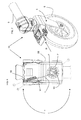
Figures 16 ,17 ,18 ,19 ,20 , an additional variant embodiment of the inventive wheel will be described, which comprises a directional stabilizer system or mechanism. - Particularly referring to
Figures 16 and17 ,numeral 10 still designates the wheel which generally also comprises a lock means 55, engaging into acorresponding seat 2A, in this example formed on thenut 2 that supports the pin P and the spring M. While the seat is shown as being formed in the nut, such seat and thestabilizer device 55 may be also located in other positions, as long as they are able to operate on a corresponding means/enclosure coaxial with the axis of rotation BB. - The lock means is returned in position, i.e. against the nut and/or the
seat 2A by aspring 15 integral with the fork at 51B. -
Figure 18 shows the operation in detail. - The lock means 55 (also known as stabilizer) is integral with a
pin 54 that may be rotated about itsaxis 54A by alever control 54B and saidspring 51. - In a given configuration, preferably having a rectilinear extension, the lock means 55 is accommodated in the
seat 2A of thenut 2; in this state thewheel 5 is locked. - The
wheel 5 is unlocked by exerting a lateral rotation stress of such intensity as to impart a rotation F1 that is large enough to disengage themeans 55 from theseat 2A in a disengagement direction, designated by D inFigure 7 . - The
means 55 will be released as it will abut against the circular profile of thenut 2 which will possibly prevent any locking thereof - because theseat 2A will be located atsuch means 55. - These two limit states are shown in the annexed
Figures 19 and20 , which show the wheel in the locked condition (lock 55 engaged in theseat 2A) and in the unlocked condition (lock 55 disengaged from theseat 2A). - Upon realignment with the
seat 2A, the action of thespring 51 will return thelock 55 into saidseat 2A and will generally provide stabilization of the rotatable support. - According to a further variant, not shown, the lock means 55 and its
seat 2A may also be located in positions other than that illustrated herein, as long as they are able to operate coaxial with the axis of rotation BB. - For instance, while the figure shows the means retained in the
support 3 of thewheel 5, in this variant embodiment, it may operate external thereto and particularly above the fork, between thefork 3 and thearm 6 or above thearm 6.
Claims (6)
- A rotatable wheel support (10), used for transferring carriages, stretchers, chairs, etc., of the type comprising a fork (3), freely rotating about a corresponding fixed vertical axis (BB), with downward lateral prongs (3B) for holding a wheel (5) that rotates about an axis of rotation (AA) parallel to the transfer plane, whereas the upper part (3C) is integral with a corresponding bearing (8) via a ring (7), through a nut (2); said bearing (8) being un turn integral with the corresponding support arm (6) via the sleeve (9), characterized in that it comprises a rod (1) which is capable of being extended by means of a return spring (M) secured between the rear swinging part (R) of the fork (3) and a fixed offset block (P) located on the nut (2) or the ring (7) of the fork (3);a. if the support (10) and the axis (BB) form an angle (. other than that of the maximum stability condition, with the spring (M) unstretched, the action of the rope (1) with the spring (M) returns said support (10) to alignment, in the above determined maximum stability configuration;b. by changing the position of the offset fixed block (P), the extension of the return spring (M) may be neutralized throughout the various angles (α) of rotation of the support (10) relative to the fixed axis (BB), to obtain infinite maximum stability positions.
- A support (10) as claimed in claim 1, characterized in that the rod (1) is capable of being extended by means of the return spring (M).
- A support (10) as claimed in claim 1, characterized in that said fixed block (P) extends downwards from the nut (2) or the ring (7) and is offset from the central point (C) of said nut (2) and/or ring (7).
- A support (10) as claimed in claim 1, characterized in that said fixed block (P) is angularly adjustable using the nut (2) or the ring (7).
- A support (10) as claimed in claim 1, characterized in that a seat (2A) is formed on the profile of said nut (2) for receiving a lock means (55) which is adapted to stabilize the wheel (5) in position; said stabilization state being maintained until exertion of one or more lateral stresses of such an intensity as to impart a rotation large enough as to disengage the means (55) from the seat (2A).
- A support (10) as claimed in claim 5, characterized in that said means (55) is returned into the corresponding seat (2A) by a spring (51) integral with the fork.
Applications Claiming Priority (1)
| Application Number | Priority Date | Filing Date | Title |
|---|---|---|---|
| IT000021A ITPR20080021A1 (en) | 2008-03-28 | 2008-03-28 | SWIVEL SUPPORT FOR WHEELS |
Publications (2)
| Publication Number | Publication Date |
|---|---|
| EP2105324A1 true EP2105324A1 (en) | 2009-09-30 |
| EP2105324B1 EP2105324B1 (en) | 2011-06-22 |
Family
ID=40293135
Family Applications (1)
| Application Number | Title | Priority Date | Filing Date |
|---|---|---|---|
| EP09156107A Active EP2105324B1 (en) | 2008-03-28 | 2009-03-25 | Rotatable wheel support |
Country Status (4)
| Country | Link |
|---|---|
| EP (1) | EP2105324B1 (en) |
| AT (1) | ATE513697T1 (en) |
| ES (1) | ES2368701T3 (en) |
| IT (1) | ITPR20080021A1 (en) |
Cited By (1)
| Publication number | Priority date | Publication date | Assignee | Title |
|---|---|---|---|---|
| WO2019166693A1 (en) * | 2018-03-01 | 2019-09-06 | K. Hartwall Oy Ab | Dolly |
Citations (5)
| Publication number | Priority date | Publication date | Assignee | Title |
|---|---|---|---|---|
| US2709829A (en) * | 1954-03-26 | 1955-06-07 | Marvin Landplane Company | Stabilized caster |
| FR2759049A1 (en) * | 1997-02-05 | 1998-08-07 | Leorat Roland | Shopping trolley |
| WO1998035841A1 (en) * | 1997-02-14 | 1998-08-20 | R & D Marine Limited | Improvements in or relating to castor wheels |
| GB2327916A (en) * | 1997-08-06 | 1999-02-10 | Ivan Dias | Trolley with locking wheels |
| WO2005005166A1 (en) * | 2003-07-09 | 2005-01-20 | Michael Stokes | Steering assembly for a trolley |
-
2008
- 2008-03-28 IT IT000021A patent/ITPR20080021A1/en unknown
-
2009
- 2009-03-25 ES ES09156107T patent/ES2368701T3/en active Active
- 2009-03-25 EP EP09156107A patent/EP2105324B1/en active Active
- 2009-03-25 AT AT09156107T patent/ATE513697T1/en not_active IP Right Cessation
Patent Citations (5)
| Publication number | Priority date | Publication date | Assignee | Title |
|---|---|---|---|---|
| US2709829A (en) * | 1954-03-26 | 1955-06-07 | Marvin Landplane Company | Stabilized caster |
| FR2759049A1 (en) * | 1997-02-05 | 1998-08-07 | Leorat Roland | Shopping trolley |
| WO1998035841A1 (en) * | 1997-02-14 | 1998-08-20 | R & D Marine Limited | Improvements in or relating to castor wheels |
| GB2327916A (en) * | 1997-08-06 | 1999-02-10 | Ivan Dias | Trolley with locking wheels |
| WO2005005166A1 (en) * | 2003-07-09 | 2005-01-20 | Michael Stokes | Steering assembly for a trolley |
Cited By (2)
| Publication number | Priority date | Publication date | Assignee | Title |
|---|---|---|---|---|
| WO2019166693A1 (en) * | 2018-03-01 | 2019-09-06 | K. Hartwall Oy Ab | Dolly |
| EP3759006A4 (en) * | 2018-03-01 | 2021-12-08 | K. Hartwall Oy AB | Dolly |
Also Published As
| Publication number | Publication date |
|---|---|
| ITPR20080021A1 (en) | 2009-09-29 |
| ES2368701T3 (en) | 2011-11-21 |
| EP2105324B1 (en) | 2011-06-22 |
| ATE513697T1 (en) | 2011-07-15 |
Similar Documents
| Publication | Publication Date | Title |
|---|---|---|
| US8128103B1 (en) | Deployable side seat for a baby stroller | |
| CN109661328B (en) | Bicycle support mounted by hanging means | |
| US8407861B1 (en) | Adjustable extension for handles | |
| US6105594A (en) | Adjustable umbrella support apparatus for use with wheel chairs, golf carts, and the like | |
| US6435538B2 (en) | Stair chair | |
| US10787188B2 (en) | Baby carriage | |
| US11313509B2 (en) | Telescoping lock mechanism | |
| AU2018223026B2 (en) | A Postural Support Bracket | |
| RU2732159C2 (en) | Scooter having a hinged or hingedly connected element | |
| JPH03501935A (en) | foldable rotating walker | |
| US7476189B2 (en) | Foldable exercise machine | |
| US9126455B1 (en) | Directional lock with release for a pivoting caster | |
| CA3015692A1 (en) | Mid-wheel tilt-in-space manual wheelchair with constant shoulder position | |
| WO2016168084A1 (en) | Stroller-attachable skateboard apparatus | |
| EP2105324A1 (en) | Rotatable wheel support | |
| US8388016B1 (en) | Stroller device for transporting lounge chairs | |
| US10966896B2 (en) | Rollator braking system | |
| JP6532431B2 (en) | Coupling device for wheeled stands for wheelchairs | |
| CN105578866B (en) | Alternating plough gauge wheel equipment | |
| US8919808B2 (en) | Stroller, especially rehab stroller | |
| US11389351B2 (en) | Wheelchair footrest assembly | |
| US20160107672A1 (en) | Anti-tipping stroller device | |
| US20100289254A1 (en) | Pushchairs | |
| US11927297B1 (en) | Canopy tilt adjustor for swing | |
| EP3501470B1 (en) | Leg rest release mechanism and wheelchair comprising the same |
Legal Events
| Date | Code | Title | Description |
|---|---|---|---|
| PUAI | Public reference made under article 153(3) epc to a published international application that has entered the european phase |
Free format text: ORIGINAL CODE: 0009012 |
|
| AK | Designated contracting states |
Kind code of ref document: A1 Designated state(s): AT BE BG CH CY CZ DE DK EE ES FI FR GB GR HR HU IE IS IT LI LT LU LV MC MK MT NL NO PL PT RO SE SI SK TR |
|
| AX | Request for extension of the european patent |
Extension state: AL BA RS |
|
| 17P | Request for examination filed |
Effective date: 20100310 |
|
| 17Q | First examination report despatched |
Effective date: 20100401 |
|
| AKX | Designation fees paid |
Designated state(s): AT BE BG CH CY CZ DE DK EE ES FI FR GB GR HR HU IE IS IT LI LT LU LV MC MK MT NL NO PL PT RO SE SI SK TR |
|
| GRAP | Despatch of communication of intention to grant a patent |
Free format text: ORIGINAL CODE: EPIDOSNIGR1 |
|
| GRAS | Grant fee paid |
Free format text: ORIGINAL CODE: EPIDOSNIGR3 |
|
| GRAA | (expected) grant |
Free format text: ORIGINAL CODE: 0009210 |
|
| AK | Designated contracting states |
Kind code of ref document: B1 Designated state(s): AT BE BG CH CY CZ DE DK EE ES FI FR GB GR HR HU IE IS IT LI LT LU LV MC MK MT NL NO PL PT RO SE SI SK TR |
|
| REG | Reference to a national code |
Ref country code: GB Ref legal event code: FG4D |
|
| REG | Reference to a national code |
Ref country code: CH Ref legal event code: EP |
|
| REG | Reference to a national code |
Ref country code: IE Ref legal event code: FG4D |
|
| REG | Reference to a national code |
Ref country code: DE Ref legal event code: R096 Ref document number: 602009001588 Country of ref document: DE Effective date: 20110804 |
|
| REG | Reference to a national code |
Ref country code: NL Ref legal event code: VDEP Effective date: 20110622 |
|
| PG25 | Lapsed in a contracting state [announced via postgrant information from national office to epo] |
Ref country code: HR Free format text: LAPSE BECAUSE OF FAILURE TO SUBMIT A TRANSLATION OF THE DESCRIPTION OR TO PAY THE FEE WITHIN THE PRESCRIBED TIME-LIMIT Effective date: 20110622 Ref country code: NO Free format text: LAPSE BECAUSE OF FAILURE TO SUBMIT A TRANSLATION OF THE DESCRIPTION OR TO PAY THE FEE WITHIN THE PRESCRIBED TIME-LIMIT Effective date: 20110922 Ref country code: LT Free format text: LAPSE BECAUSE OF FAILURE TO SUBMIT A TRANSLATION OF THE DESCRIPTION OR TO PAY THE FEE WITHIN THE PRESCRIBED TIME-LIMIT Effective date: 20110622 Ref country code: SE Free format text: LAPSE BECAUSE OF FAILURE TO SUBMIT A TRANSLATION OF THE DESCRIPTION OR TO PAY THE FEE WITHIN THE PRESCRIBED TIME-LIMIT Effective date: 20110622 |
|
| REG | Reference to a national code |
Ref country code: ES Ref legal event code: FG2A Ref document number: 2368701 Country of ref document: ES Kind code of ref document: T3 Effective date: 20111121 |
|
| PG25 | Lapsed in a contracting state [announced via postgrant information from national office to epo] |
Ref country code: GR Free format text: LAPSE BECAUSE OF FAILURE TO SUBMIT A TRANSLATION OF THE DESCRIPTION OR TO PAY THE FEE WITHIN THE PRESCRIBED TIME-LIMIT Effective date: 20110923 Ref country code: SI Free format text: LAPSE BECAUSE OF FAILURE TO SUBMIT A TRANSLATION OF THE DESCRIPTION OR TO PAY THE FEE WITHIN THE PRESCRIBED TIME-LIMIT Effective date: 20110622 Ref country code: CY Free format text: LAPSE BECAUSE OF FAILURE TO SUBMIT A TRANSLATION OF THE DESCRIPTION OR TO PAY THE FEE WITHIN THE PRESCRIBED TIME-LIMIT Effective date: 20110622 Ref country code: AT Free format text: LAPSE BECAUSE OF FAILURE TO SUBMIT A TRANSLATION OF THE DESCRIPTION OR TO PAY THE FEE WITHIN THE PRESCRIBED TIME-LIMIT Effective date: 20110622 Ref country code: LV Free format text: LAPSE BECAUSE OF FAILURE TO SUBMIT A TRANSLATION OF THE DESCRIPTION OR TO PAY THE FEE WITHIN THE PRESCRIBED TIME-LIMIT Effective date: 20110622 Ref country code: FI Free format text: LAPSE BECAUSE OF FAILURE TO SUBMIT A TRANSLATION OF THE DESCRIPTION OR TO PAY THE FEE WITHIN THE PRESCRIBED TIME-LIMIT Effective date: 20110622 |
|
| PG25 | Lapsed in a contracting state [announced via postgrant information from national office to epo] |
Ref country code: NL Free format text: LAPSE BECAUSE OF FAILURE TO SUBMIT A TRANSLATION OF THE DESCRIPTION OR TO PAY THE FEE WITHIN THE PRESCRIBED TIME-LIMIT Effective date: 20110622 Ref country code: BE Free format text: LAPSE BECAUSE OF FAILURE TO SUBMIT A TRANSLATION OF THE DESCRIPTION OR TO PAY THE FEE WITHIN THE PRESCRIBED TIME-LIMIT Effective date: 20110622 |
|
| PG25 | Lapsed in a contracting state [announced via postgrant information from national office to epo] |
Ref country code: PT Free format text: LAPSE BECAUSE OF FAILURE TO SUBMIT A TRANSLATION OF THE DESCRIPTION OR TO PAY THE FEE WITHIN THE PRESCRIBED TIME-LIMIT Effective date: 20111024 Ref country code: EE Free format text: LAPSE BECAUSE OF FAILURE TO SUBMIT A TRANSLATION OF THE DESCRIPTION OR TO PAY THE FEE WITHIN THE PRESCRIBED TIME-LIMIT Effective date: 20110622 Ref country code: IS Free format text: LAPSE BECAUSE OF FAILURE TO SUBMIT A TRANSLATION OF THE DESCRIPTION OR TO PAY THE FEE WITHIN THE PRESCRIBED TIME-LIMIT Effective date: 20111022 Ref country code: CZ Free format text: LAPSE BECAUSE OF FAILURE TO SUBMIT A TRANSLATION OF THE DESCRIPTION OR TO PAY THE FEE WITHIN THE PRESCRIBED TIME-LIMIT Effective date: 20110622 |
|
| PG25 | Lapsed in a contracting state [announced via postgrant information from national office to epo] |
Ref country code: PL Free format text: LAPSE BECAUSE OF FAILURE TO SUBMIT A TRANSLATION OF THE DESCRIPTION OR TO PAY THE FEE WITHIN THE PRESCRIBED TIME-LIMIT Effective date: 20110622 Ref country code: SK Free format text: LAPSE BECAUSE OF FAILURE TO SUBMIT A TRANSLATION OF THE DESCRIPTION OR TO PAY THE FEE WITHIN THE PRESCRIBED TIME-LIMIT Effective date: 20110622 |
|
| PLBE | No opposition filed within time limit |
Free format text: ORIGINAL CODE: 0009261 |
|
| STAA | Information on the status of an ep patent application or granted ep patent |
Free format text: STATUS: NO OPPOSITION FILED WITHIN TIME LIMIT |
|
| 26N | No opposition filed |
Effective date: 20120323 |
|
| PG25 | Lapsed in a contracting state [announced via postgrant information from national office to epo] |
Ref country code: DK Free format text: LAPSE BECAUSE OF FAILURE TO SUBMIT A TRANSLATION OF THE DESCRIPTION OR TO PAY THE FEE WITHIN THE PRESCRIBED TIME-LIMIT Effective date: 20110622 |
|
| REG | Reference to a national code |
Ref country code: DE Ref legal event code: R097 Ref document number: 602009001588 Country of ref document: DE Effective date: 20120323 |
|
| PG25 | Lapsed in a contracting state [announced via postgrant information from national office to epo] |
Ref country code: MC Free format text: LAPSE BECAUSE OF NON-PAYMENT OF DUE FEES Effective date: 20120331 |
|
| REG | Reference to a national code |
Ref country code: IE Ref legal event code: MM4A |
|
| PG25 | Lapsed in a contracting state [announced via postgrant information from national office to epo] |
Ref country code: IE Free format text: LAPSE BECAUSE OF NON-PAYMENT OF DUE FEES Effective date: 20120325 |
|
| PG25 | Lapsed in a contracting state [announced via postgrant information from national office to epo] |
Ref country code: MK Free format text: LAPSE BECAUSE OF FAILURE TO SUBMIT A TRANSLATION OF THE DESCRIPTION OR TO PAY THE FEE WITHIN THE PRESCRIBED TIME-LIMIT Effective date: 20110622 |
|
| PG25 | Lapsed in a contracting state [announced via postgrant information from national office to epo] |
Ref country code: BG Free format text: LAPSE BECAUSE OF FAILURE TO SUBMIT A TRANSLATION OF THE DESCRIPTION OR TO PAY THE FEE WITHIN THE PRESCRIBED TIME-LIMIT Effective date: 20110922 |
|
| PG25 | Lapsed in a contracting state [announced via postgrant information from national office to epo] |
Ref country code: MT Free format text: LAPSE BECAUSE OF FAILURE TO SUBMIT A TRANSLATION OF THE DESCRIPTION OR TO PAY THE FEE WITHIN THE PRESCRIBED TIME-LIMIT Effective date: 20110622 |
|
| REG | Reference to a national code |
Ref country code: CH Ref legal event code: PL |
|
| PG25 | Lapsed in a contracting state [announced via postgrant information from national office to epo] |
Ref country code: CH Free format text: LAPSE BECAUSE OF NON-PAYMENT OF DUE FEES Effective date: 20130331 Ref country code: LI Free format text: LAPSE BECAUSE OF NON-PAYMENT OF DUE FEES Effective date: 20130331 |
|
| PG25 | Lapsed in a contracting state [announced via postgrant information from national office to epo] |
Ref country code: TR Free format text: LAPSE BECAUSE OF FAILURE TO SUBMIT A TRANSLATION OF THE DESCRIPTION OR TO PAY THE FEE WITHIN THE PRESCRIBED TIME-LIMIT Effective date: 20110622 |
|
| PG25 | Lapsed in a contracting state [announced via postgrant information from national office to epo] |
Ref country code: LU Free format text: LAPSE BECAUSE OF NON-PAYMENT OF DUE FEES Effective date: 20120325 |
|
| PG25 | Lapsed in a contracting state [announced via postgrant information from national office to epo] |
Ref country code: HU Free format text: LAPSE BECAUSE OF FAILURE TO SUBMIT A TRANSLATION OF THE DESCRIPTION OR TO PAY THE FEE WITHIN THE PRESCRIBED TIME-LIMIT Effective date: 20090325 |
|
| REG | Reference to a national code |
Ref country code: FR Ref legal event code: PLFP Year of fee payment: 8 |
|
| REG | Reference to a national code |
Ref country code: FR Ref legal event code: PLFP Year of fee payment: 9 |
|
| PGFP | Annual fee paid to national office [announced via postgrant information from national office to epo] |
Ref country code: DE Payment date: 20170322 Year of fee payment: 9 |
|
| PGFP | Annual fee paid to national office [announced via postgrant information from national office to epo] |
Ref country code: GB Payment date: 20170322 Year of fee payment: 9 |
|
| REG | Reference to a national code |
Ref country code: FR Ref legal event code: PLFP Year of fee payment: 10 |
|
| REG | Reference to a national code |
Ref country code: DE Ref legal event code: R119 Ref document number: 602009001588 Country of ref document: DE |
|
| GBPC | Gb: european patent ceased through non-payment of renewal fee |
Effective date: 20180325 |
|
| PG25 | Lapsed in a contracting state [announced via postgrant information from national office to epo] |
Ref country code: DE Free format text: LAPSE BECAUSE OF NON-PAYMENT OF DUE FEES Effective date: 20181002 |
|
| PG25 | Lapsed in a contracting state [announced via postgrant information from national office to epo] |
Ref country code: GB Free format text: LAPSE BECAUSE OF NON-PAYMENT OF DUE FEES Effective date: 20180325 |
|
| PGFP | Annual fee paid to national office [announced via postgrant information from national office to epo] |
Ref country code: FR Payment date: 20210330 Year of fee payment: 13 Ref country code: IT Payment date: 20210330 Year of fee payment: 13 |
|
| PGFP | Annual fee paid to national office [announced via postgrant information from national office to epo] |
Ref country code: ES Payment date: 20210525 Year of fee payment: 13 |
|
| PG25 | Lapsed in a contracting state [announced via postgrant information from national office to epo] |
Ref country code: FR Free format text: LAPSE BECAUSE OF NON-PAYMENT OF DUE FEES Effective date: 20220331 |
|
| REG | Reference to a national code |
Ref country code: ES Ref legal event code: FD2A Effective date: 20230508 |
|
| PG25 | Lapsed in a contracting state [announced via postgrant information from national office to epo] |
Ref country code: IT Free format text: LAPSE BECAUSE OF NON-PAYMENT OF DUE FEES Effective date: 20220325 |
|
| PG25 | Lapsed in a contracting state [announced via postgrant information from national office to epo] |
Ref country code: ES Free format text: LAPSE BECAUSE OF NON-PAYMENT OF DUE FEES Effective date: 20220326 |