EP2105230A1 - Insert clamping wedge and insert-detachable type cutter - Google Patents
Insert clamping wedge and insert-detachable type cutter Download PDFInfo
- Publication number
- EP2105230A1 EP2105230A1 EP09156280A EP09156280A EP2105230A1 EP 2105230 A1 EP2105230 A1 EP 2105230A1 EP 09156280 A EP09156280 A EP 09156280A EP 09156280 A EP09156280 A EP 09156280A EP 2105230 A1 EP2105230 A1 EP 2105230A1
- Authority
- EP
- European Patent Office
- Prior art keywords
- insert
- wedge
- clamp
- recessed
- recessed portion
- Prior art date
- Legal status (The legal status is an assumption and is not a legal conclusion. Google has not performed a legal analysis and makes no representation as to the accuracy of the status listed.)
- Granted
Links
Images




Classifications
-
- B—PERFORMING OPERATIONS; TRANSPORTING
- B23—MACHINE TOOLS; METAL-WORKING NOT OTHERWISE PROVIDED FOR
- B23C—MILLING
- B23C5/00—Milling-cutters
- B23C5/16—Milling-cutters characterised by physical features other than shape
- B23C5/20—Milling-cutters characterised by physical features other than shape with removable cutter bits or teeth or cutting inserts
- B23C5/22—Securing arrangements for bits or teeth or cutting inserts
- B23C5/2265—Securing arrangements for bits or teeth or cutting inserts by means of a wedge
- B23C5/2269—Securing arrangements for bits or teeth or cutting inserts by means of a wedge for plate-like cutting inserts
-
- B—PERFORMING OPERATIONS; TRANSPORTING
- B23—MACHINE TOOLS; METAL-WORKING NOT OTHERWISE PROVIDED FOR
- B23C—MILLING
- B23C2210/00—Details of milling cutters
- B23C2210/20—Number of cutting edges
- B23C2210/206—Number of cutting edges seven
-
- Y—GENERAL TAGGING OF NEW TECHNOLOGICAL DEVELOPMENTS; GENERAL TAGGING OF CROSS-SECTIONAL TECHNOLOGIES SPANNING OVER SEVERAL SECTIONS OF THE IPC; TECHNICAL SUBJECTS COVERED BY FORMER USPC CROSS-REFERENCE ART COLLECTIONS [XRACs] AND DIGESTS
- Y10—TECHNICAL SUBJECTS COVERED BY FORMER USPC
- Y10T—TECHNICAL SUBJECTS COVERED BY FORMER US CLASSIFICATION
- Y10T407/00—Cutters, for shaping
- Y10T407/19—Rotary cutting tool
- Y10T407/1906—Rotary cutting tool including holder [i.e., head] having seat for inserted tool
-
- Y—GENERAL TAGGING OF NEW TECHNOLOGICAL DEVELOPMENTS; GENERAL TAGGING OF CROSS-SECTIONAL TECHNOLOGIES SPANNING OVER SEVERAL SECTIONS OF THE IPC; TECHNICAL SUBJECTS COVERED BY FORMER USPC CROSS-REFERENCE ART COLLECTIONS [XRACs] AND DIGESTS
- Y10—TECHNICAL SUBJECTS COVERED BY FORMER USPC
- Y10T—TECHNICAL SUBJECTS COVERED BY FORMER US CLASSIFICATION
- Y10T407/00—Cutters, for shaping
- Y10T407/19—Rotary cutting tool
- Y10T407/1906—Rotary cutting tool including holder [i.e., head] having seat for inserted tool
- Y10T407/1908—Face or end mill
- Y10T407/192—Face or end mill with separate means to fasten tool to holder
- Y10T407/1922—Wedge clamp element
-
- Y—GENERAL TAGGING OF NEW TECHNOLOGICAL DEVELOPMENTS; GENERAL TAGGING OF CROSS-SECTIONAL TECHNOLOGIES SPANNING OVER SEVERAL SECTIONS OF THE IPC; TECHNICAL SUBJECTS COVERED BY FORMER USPC CROSS-REFERENCE ART COLLECTIONS [XRACs] AND DIGESTS
- Y10—TECHNICAL SUBJECTS COVERED BY FORMER USPC
- Y10T—TECHNICAL SUBJECTS COVERED BY FORMER US CLASSIFICATION
- Y10T407/00—Cutters, for shaping
- Y10T407/19—Rotary cutting tool
- Y10T407/1906—Rotary cutting tool including holder [i.e., head] having seat for inserted tool
- Y10T407/1908—Face or end mill
- Y10T407/1924—Specified tool shape
-
- Y—GENERAL TAGGING OF NEW TECHNOLOGICAL DEVELOPMENTS; GENERAL TAGGING OF CROSS-SECTIONAL TECHNOLOGIES SPANNING OVER SEVERAL SECTIONS OF THE IPC; TECHNICAL SUBJECTS COVERED BY FORMER USPC CROSS-REFERENCE ART COLLECTIONS [XRACs] AND DIGESTS
- Y10—TECHNICAL SUBJECTS COVERED BY FORMER USPC
- Y10T—TECHNICAL SUBJECTS COVERED BY FORMER US CLASSIFICATION
- Y10T407/00—Cutters, for shaping
- Y10T407/19—Rotary cutting tool
- Y10T407/1906—Rotary cutting tool including holder [i.e., head] having seat for inserted tool
- Y10T407/1934—Rotary cutting tool including holder [i.e., head] having seat for inserted tool with separate means to fasten tool to holder
- Y10T407/1938—Wedge clamp element
-
- Y—GENERAL TAGGING OF NEW TECHNOLOGICAL DEVELOPMENTS; GENERAL TAGGING OF CROSS-SECTIONAL TECHNOLOGIES SPANNING OVER SEVERAL SECTIONS OF THE IPC; TECHNICAL SUBJECTS COVERED BY FORMER USPC CROSS-REFERENCE ART COLLECTIONS [XRACs] AND DIGESTS
- Y10—TECHNICAL SUBJECTS COVERED BY FORMER USPC
- Y10T—TECHNICAL SUBJECTS COVERED BY FORMER US CLASSIFICATION
- Y10T407/00—Cutters, for shaping
- Y10T407/22—Cutters, for shaping including holder having seat for inserted tool
- Y10T407/2222—Tool adjustable relative to holder
- Y10T407/2252—Rectilinearly
- Y10T407/2256—Rectilinearly including wedge clamp element
-
- Y—GENERAL TAGGING OF NEW TECHNOLOGICAL DEVELOPMENTS; GENERAL TAGGING OF CROSS-SECTIONAL TECHNOLOGIES SPANNING OVER SEVERAL SECTIONS OF THE IPC; TECHNICAL SUBJECTS COVERED BY FORMER USPC CROSS-REFERENCE ART COLLECTIONS [XRACs] AND DIGESTS
- Y10—TECHNICAL SUBJECTS COVERED BY FORMER USPC
- Y10T—TECHNICAL SUBJECTS COVERED BY FORMER US CLASSIFICATION
- Y10T407/00—Cutters, for shaping
- Y10T407/22—Cutters, for shaping including holder having seat for inserted tool
- Y10T407/2272—Cutters, for shaping including holder having seat for inserted tool with separate means to fasten tool to holder
- Y10T407/2282—Cutters, for shaping including holder having seat for inserted tool with separate means to fasten tool to holder including tool holding clamp and clamp actuator
- Y10T407/2284—Wedge clamp element
Definitions
- the present invention relates to an insert clamping wedge (hereinafter, referred to as a clamp wedge) which is used to detachably clamp-fix a cutting insert to an insert attachment seat of a cutter body in an insert-detachable type cutter such as a face mill and also relates to an insert-detachable type cutter which is mounted with the clamp wedge so as to attach the cutting insert thereto.
- a clamp wedge an insert clamping wedge which is used to detachably clamp-fix a cutting insert to an insert attachment seat of a cutter body in an insert-detachable type cutter such as a face mill
- an insert-detachable type cutter which is mounted with the clamp wedge so as to attach the cutting insert thereto.
- the insert-detachable type cutter includes a cutter body, a cutting insert, and a clamp wedge which is used to fix the cutting insert to the cutter body.
- the cutter body is provided with an insert attachment seat and a recessed portion which communicates with the insert attachment seat.
- the cutting insert is seated in the insert attachment seat.
- the clamp wedge is inserted into the recessed portion.
- the clamp wedge is pressed by a pressing member such as a clamp screw so as to be inserted into the cutter body along a wedge surface of the clamp wedge.
- a pressing member such as a clamp screw
- the cutting insert having a polygonal flat plate shape seated in the insert attachment seat is pressed into the insert attachment seat in a thickness direction so as to be clamp-fixed thereto by means of a clamp surface of the clamp wedge.
- the surface of the clamp wedge is inclined so that the distance between the wedge surface and the surface of the clamp wedge becomes smaller in a press-insertion direction.
- a section perpendicular to the press-insertion direction is formed such that the clamp surface is formed in a square shape and the wedge surface is formed in a semicircular are shape which has the same width as that of the square shape and is smoothly connected to the square shape. That is, the clamp wedge is formed in a semicircular arc shape (barrel roof shape or vault shape). Accordingly, when the width of the clamp surface in the section increases in order to increase the area of the clamp surface, the radius of the semicircular arc shape of the wedge surface increases. That is, when the area of the clamp surface increases, the wedge body simply increases in size.
- the recessed portion of the cutter body mounted with the clamp wedge increases in size.
- the distance between the recessed portion and the outer peripheral surface of the cutter body becomes smaller. Accordingly, when the clamp wedge is pressed so as to clamp the insert, the clamping strength may deteriorate or the thinned portion may be deformed or damaged.
- an object of the present invention is to provide a clamp wedge and an insert-detachable type cutter capable of preventing a sectional area of a wedge body and a recessed portion perpendicular to a press-insertion direction of a wedge body from excessively increasing, of maintaining the thickness of a cutter body, and of ensuring a large area of a clamp surface by enlarging the width of the clamp surface.
- a clamp wedge according to the present invention has the following characteristic configuration.
- the clamp wedge according to the present invention is an insert clamping wedge which clamp-fixes a cutting insert, seated in an insert attachment seat formed in a cutter body, to the insert attachment seat.
- a wedge body pressed into the cutter body is provided with a clamp surface which comes into close contact with the cutting insert and a wedge surface of which the gap between the wedge surface and the clamp surface becomes smaller in a press-insertion direction of the wedge body.
- An external shape of the wedge surface in a section perpendicular to the press-insertion direction of the wedge body includes a protruded curve portion and recessed curve portions of which the distance therebetween becomes larger in a direction from both ends of the protruded curve portion toward the clamp surface. That is, the section from the wedge surface to the clamp surface is formed in a bell shape.
- the clamp wedge is mounted to the recessed portion, formed in the cutter body so as to communicate with the insert attachment seat, in such a manner that the wedge surface is pressed by a pressing member so as to come into slidable contact with an inner wall surface of the recessed portion.
- the sectional shape perpendicular to the press-insertion direction of the wedge body is formed in a bell shape- That is, in the wedge surface of the wedge body, both ends of the protruded curve form a recessed curve to thereby form a narrowed shape. Accordingly, even when the width of the clamp surface increases to ensure a large area, it is possible to prevent the sectional area of the wedge body and the recessed portion perpendicular to the press-insertion direction from excessively increasing. As a result, it is possible to cope with an increase in the number of cutting blades by using the clamp wedge according to the present invention.
- the clamp wedge according to the present invention is used. Accordingly, even when the member of cutting blades increases, it is possible to prevent the cutter body from being deformed or damaged by maintaining the thickness in the periphery of the recessed portion of the cutter body and to strongly fix the cutting insert by improving the clamping strength.
- the wedge surface of the wedge body of the clamp wedge is formed by a region from the protruded curve portion to at least the recessed curve portions in both ends thereof. That is, the gap between the wedge surface and the clamp surface becomes smaller in the press-insertion direction of the wedge body.
- the cutter body may have the following configuration That is, in a section perpendicular to the press-insertion direction, each of opening peripheries of the recessed portion of the cutter body are formed in a recessed surface which rises up in a direction opposite to the press-insertion direction as the distance from the clamping wedge in a diameter direction of the cutter body becomes greater. Accordingly, even when the gap between the insert attachment seat and the recessed portion is limited due to the increase in the number of cutting blades, it is possible to ensure a large thickness in both ends of the periphery of the recessed portion of the cutter body in the press-insertion direction. As a result, it is possible to improve the clamping strength by ensuring the rigidity of the periphery of the recessed portion of the cutter body.
- the opening periphery of the recessed portion when the recessed portion is located on the side of the rake face of the cutting insert fixed to the insert attachment seat, the opening periphery of the recessed portion, of which rises up to be formed in a recessed surface shape, may be formed in a recessed curve shape.
- the present invention it is possible to maintain the small thickness of the cutter body by preventing the sectional area of the wedge body or the recessed portion from increasing even in the insert-detachable type cutter having a plural of blades. Accordingly, according to the present invention, it is possible to prevent a deformation or damage of the cutter body and to improve the clamping strength. In addition, since it is possible to obtain the clamp surface having a large area by enlarging the width of a clamp surface of the clamp wedge, the cutting insert can be strongly fixed. As a result, it is possible to efficiently and highly precisely carry out a cutting process in a stable manner.
- FIGS. 1 to 14 are views showing a clamp wedge and an insert-detachable type cutter according to an embodiment of the present invention.
- a cutter body 1 is formed of steel or the like so as to have a substantially disc shape as shown in FIG. 1 .
- the rear end side (the upper side of FIG. 1 ) of the cutter body 1 in a central axial direction is formed as an attachment portion 2 which is attached to a main shaft of a machine tool.
- the from end side (the lower side of FIG. 1 ) of the cutter body 1 is formed as a blade portion 3 having a diameter larger than that of the attachment portion 2 by one level.
- the cutter body 1 is configured to rotate about the central axis in a cutter rotation direction T so as to be used in which a workpiece is cut.
- the front-end outer peripheral side of the blade portion 3 is provided with an insert attachment seat 4 which is formed by cutting the rear-end inner peripheral side of the blade portion 3 so as to fix a cutting insert 21 thereto in a seated state as described below. Also, the front-end outer peripheral side thereof is provided with a chip pocket 5 and a recessed portion 6 which communicate with each other in the insert attachment seat 4 in the cutter rotation direction T. Plural groups each including the insert attachment seat 4, the chip pocket 5, and the recessed portion 6 are arranged in a circumferential direction of the blade portion 3 so as to have a predetermined interval therebetween.
- a clamp wedge 10 according to this embodiment is inserted into the recessed portion 6 so as to be pressed toward the rear-end inner peripheral side of the cutter body 1 by means of a clamp screw 11 (pressing member 11) of which both ends are provided with a male screw portion. Accordingly, the cutting insert 21 is pressed into the insert attachment seat 4 so as to be clamp-fixed thereto.
- FIGS. 11 and 14 show the insert-detachable type cutter in which each cutting insert 21 is accommodated in each insert attachment seat 4 and is pressed by each clamp wedge 10 so as to be clamped thereto.
- the cutting insert attached to the insert-detachable type cutter is formed of a hard material such as hard metal so as to have a regular polygonal (for example, a regular heptagonal) flat plate shape.
- An example of the cutting insert is shown in FIG 15 .
- the cutting insert 21 having a flat plate shape shown in this example has a configuration in which both side surfaces are formed parallel to each other in a substantially regular heptagonal shape, one side surface is formed as a rake face 23, and then the other side surface is formed as a seat surface 22 facing the insert attachment seat 4.
- a cutting blade is formed in a side ridge of the rake face.
- the cutting insert 21 is formed as a hollow insert in which a circular hole is formed in the center of the rake face in a sectional view, and the rake face is formed as a surface having a hole formed therethrough.
- the insert attachment seat 4, on which the hollow cutting insert 21 is seated includes a flat bottom surface 4A facing the cutter rotation direction T and a pair of wall surfaces 4B uprightly formed from the side ridges on the inner peripheral side and the rear end side of the cutter body 1 of the bottom surface 4A.
- Two side surfaces of the hollow insert 21 respectively come into contact with the wall surfaces 4B so as to allow the rake face 23 to face the cutter rotation direction T
- the seat surface 22 of the hollow insert comes into close contact with the bottom surface 4A, and the hollow insert is seated in the insert attachment seat 4.
- the insert-detachable type cutter is a face mill
- one of seven cutting blades of the cutting insert 21 is located on one plane perpendicular to the central axis of the face mill.
- the chip pocket 5 is formed to be widened toward the outer peripheral side of the cutter body 1 (the upper side of FIG. 4 ) in the cutter rotation direction T.
- the recessed portion 6 is opened at the center portion of the bottom surface 5A of the chip pocket 5 facing the outer peripheral side of the cutter body 1 so as to have a gap with respect to the peripheral surface of the cutter body 1. Also, the recessed portion 6 extends to the rear-end inner peripheral side of the cutter body 1 so as to communicate with the insert attachment seat 4.
- the recessed portion 6 includes a bottom surface 6A which is located on the rear-end inner peripheral side of the cutter body 1 and an inner wall surface 6B which extends from the bottom surface 5A of the chip pocket 5 toward the bottom surface 6A and the rear-end inner peripheral side of the cutter body 1.
- the bottom surface 6A is provided with a screw hole 6C into which the male screw portion of one end of the clamp screw 11 is threaded.
- the screw hole 6C faces the rear-end inner peripheral side of the cutter body 1 and the bottom surface 4A of the insert attachment seat 4 so as to extend in a direction in which the pair of wall surfaces 4B intersects each other.
- the inner wall surface 6B extends in parallel 10 the central axis of the screw hole 6C.
- the direction facing the inside (rear-end inner peripheral side) of the cutter body 1 along the central axis of the screw hole 6C corresponds to the direction in which the clamp wedge 10 according to this embodiment is pressed.
- the recessed portion 6 is formed in a complementary shape with respect to the shape of the clamp wedge 10.
- a wedge body 12 is formed of steel or the like. As shown in FIGS. 5 and 6A to 6C , the clamp wedge 10 is formed in a hollow piece shape. The hollow portion is formed as a screw hole 13 into which the male screw portion of the other end of the clamp screw 11 is threaded.
- the wedge body 12 is inserted into the recessed portion 6 in such a manner that one end surface 12A faces the front-end outer peripheral side (front side) of the cutter body 1 and the other end surface 12B faces the bottom surface 6A of the recessed portion 6.
- the clamp wedge 10 is pressed into the recessed portion 6 in a direction toward the rear-end inner peripheral side of the cutter body 1 by respectively threading the male screw portions of both ends of the clamp screw 11 into the screw hole 13 of the clamp wedge 10 and the screw hole 6C. Accordingly, in the clamp wedge 10, the direction from the end surface 12A to the end surface 12B along the central axis C of the screw hole 13 corresponds to the press-insertion direction.
- One of side surfaces extending between both end surfaces 12A and 12B of the wedge body 12 is formed as a clamp surface 14 which comes into close contact with the rake face of the hollow insert in a direction toward the insert attachment seat 4 when the clamp wedge 10 is pressed into the recessed portion 6.
- a protrusion 15 is formed at the center of the clamp surface 14.
- a recessed groove portion 14A is formed so as to be slightly recessed from the clamp surface 14.
- the whole surface of the clamp surface 14 except for the protrusion 15 and the recessed groove portion 14A is formed in an inclined plane shape in which the inclined plane becomes closer to the central axis C of the screw hole 13 in a direction toward the end surface 12A at an inclined angle formed between the central axis of the screw hole 6C and the bottom surface 4A of the insert attachment seat 4.
- the inclined plane shape is formed so as to surround the protrusion 15 and the recessed groove portion 14A.
- the surface of the protrusion 15 is formed in a spherical shape.
- the section taken along the clamp surface 14 and the section parallel to the clamp surface 14 are formed in a circular shape.
- the protrusion height of the protrusion 15 from the clamp surface 14 is set to be sufficiently smaller than the radius of the circle formed by the protrusion 15 in the section taken along the clamp surface 14.
- the radius of the circle in the section is set to be smaller than the radius of the circle formed by the opening of the rake face of the hollow insert. That is, the protrusion 15 is configured to be accommodated in the hole of the rake face of the hollow insert when the clamp wedge 10 is pressed into the recessed portion 6 so that the clamp surface 14 comes into close contact with the perforated surface of the hollow insert.
- the side surface of the wedge body 12 facing the opposite side of the clamp surface 14 is formed as a wedge surface 16.
- the wedge surface 16 is formed as a surface (a contact surface in a movable state) which comes into slidable contact with the inner wall surface 6B when the clamp wedge 10 is pressed into the recessed portion 6 of the cutter body 1.
- the wedge surface 16 extends in a direction parallel to the central axis C between both end surfaces 12A and 12B so that the section perpendicular to the central axis C, that is, the section perpendicular to the press-insertion direction is uniform.
- Aside surface is farmed between the wedge surface 16 and the clamp surface 14 so as to be perpendicular to the clamp surface 14 and to be parallel to the central axis C, and the clamp surface 14 is inclined with respect to the central axis C. Accordingly, the width of the side surface becomes narrow in a direction toward the end surface 12B.
- a protruded curve portion 16A and recessed curve portions 16B are formed in a section of the wedge surface 16 which is perpendicular to the press-insertion direction.
- the protruded curve portion 16A is a protruded curve portion (barrel roof shape parts or vault shape parts) which forms a protruded curve having a semicircular arc shape (a half of a circular arc) with respect to the central axis C.
- Each recessed curve portion 16B is a recessed curve portion which faces the clamp surface 14 and is formed in a recessed curve such as a recessed circular arc which smoothly connects both ends of the protruded curve portion 16A to the protruded curve portion 16A.
- the recessed curve portions 16B widen toward the clamp surface 14 in a direction in which the clamp surface 14 extends in the section. (a vertical direction of FIG. 6A and a horizontal direction of FIG 6C ) and is connected to the side surface. Accordingly, in this embodiment, the shape perpendicular to the press-insertion direction of the wedge body 12 is a bell shape shown in FIG. 6A .
- a ratio between the width of the clamp surface ( ⁇ of FIG. 6A ) and the diameter ( ⁇ of FIG. 6A ) of the semicircular are about the central axis C of the protruded curve portion 16A is not limited, but is desirably equal to or more than 60 % and less than 100 %, and more desirably equal to or more than 70 % and equal to or less than 80 %.
- the sectional shape of the inner wall surface 6B of the recessed portion 6 of the cutter body has a ressed-protruded shape opposite to a recessed-protruded shape of the wedge surface 16, the inner wall surface 6B being configured to come into contact with the wedge surface 16 when the clamp wedge 10 is pressed into the recessed portion 6.
- the sectional shape of the inner wall surface 6B includes a recessed curve portion which forms a recessed curve having a semicircular arc shape (a half of a circular arc) about the central axis of the screw hole 6C and a protruded curve portion which forms a protruded curve such as a protruded circular arc smoothly connecting both ends of the recessed curve portion to the recessed curve portion so as to be widened in a direction toward the insert attachment seat 6.
- the bottom surface 5A of the chip pocket 5 of the cutter body 1 is formed in a shape (a recessed surface shape or a bowl shape) which rises up in a direction opposite to the press-insertion direction, the bottom surface 5A corresponding to the periphery of the opening where the recessed portion 6 is opened. That is, in the section perpendicular to the press-insertion direction, that is, the section perpendicular to the central axis of the screw hole 6C, the bottom surface 5A is formed in a recessed surface shape which rises up in a direction (the front side of FIGS.
- the recessed surface formed by the bottom surface 5A is formed in a recessed curve surface shape. That is, the bottom surface 5A on the side of the recessed portion 6 is formed in a recessed curve shape in the section including the central axis of the screw hole 6C and perpendicular to the bottom surface 4A of the insert attachment seat 4.
- the bottom surface 5A is formed in a recessed curve surface shape which rises up to the front-end outer peripheral side of the cutter body 1 so as to be connected to the peripheral surface of the cutter body 1 as the bottom surface 5A becomes closer to the rear-end outer peripheral side and the front-end inner peripheral side of the cutter body 1 in a direction perpendicular to the plane forming the section (see FIG. 4 ).
- the hollow insert is attached to the insert-detachable type cutter having the above-described configuration, First, the wedge surface 16 comes into slidable contact with the inner wall surface 6B so as to insert the clamp wedge 10 into the recessed portion 6. Subsequently, the clamp screw 11 is threaded into the screw hole 13 of the wedge body 12 and the screw hole 6C of the recessed portion 6 so as to temporarily fix the clamp wedge 10 to the cutter body 1. Subsequently, the hollow insert is seated in the insert attachment seat 4 as described above. Subsequently, the clamp screw 11 is threaded again so as to press the clamp wedge 10 into the recessed portion 6.
- the protrusion 15 of the clamp wedge 10 is accommodated in the hole of the hollow insert, and the clamp surface 14 comes into close contact with the perforated surface so as to press the hollow insert into the bottom surface 4A of the insert attachment seat 4. Accordingly, the hollow insert is fixed in a clamped state.
- the protrusion 15 may come into contact with the opening peripheral edge of the hole so as to draw the hollow insert in a direction in which the pair of wall surfaces 4B intersects each other.
- the clamp wedge 10 which clamps the hollow insert is formed in a bell shape. That is, the section perpendicular to the press-insertion direction of the wedge body 12 is formed in a bell shape including the protruded curve portion 16A in which the wedge surface 16 on the opposite side of the clamp surface 14 forms a protruded curve having a semicircular arc shape and the pair of recessed curve portions 16B which forms a recessed curve shape from both ends thereof so that the width therebetween becomes large.
- the sectional area being perpendicular to the press-insertion direction.
- each recessed curve portion 16B is inclined in a direction from the end surface 12A of the wedge body 12 to the end surface 12B, that is, the press-insertion direction so that a gap between itself and the clamp surface 14 becomes small. Accordingly, it is possible to reliably apply the pressing force to both widened side portions of the clamp surface 14 on the under side of the recessed curve portion 16B. Accordingly, it is possible to further strongly clamp-fix the cutting insert, and thus to highly precisely carry out the cutting process in a stabler manner.
- the bottom surface 5A of the chip pocket 5 is formed in a recessed surface shape, the bottom surface 5A corresponding to the periphery of the opening where the recessed portion 6 of the cutter body 1 is opened. That is, in a section perpendicular to the press-insertion, direction, the bottom surface 5A is formed in a recessed surface shape which rises up in a direction opposite to the press-insertion direction as the distance from the clamping wedge 10 in a diameter direction of the cutter body becomes greater.
- the chip pocket 5, and the recessed portion 6 is limited to be small due to an increase in the number of blades, it is possible to ensure a large thickness of the cutter body 1 in the periphery of the recessed portion 6. Accordingly, it is possible to improve the rigidity in the periphery of the recessed portion 6. As a result, it is possible to strongly carry out the insert attaching operation in a stable manner by reliably ensuring the clamping strength.
- a section perpendicular to the plane including the central axis of the screw hole 6C and perpendicular to the bottom surface 4A of the insert attachment seat 4 may be formed in a V-shape.
- the bottom surface 5A on the side of the recessed portion 6 forms the most recessed curve so as to rises up in a direction opposite to the press-insertion diction as the distance from the clamping wedge (10, 20, 30) in a diameter direction of the cutter body becomes greater, that is, toward the rear-end outer peripheral side and the front-end inner peripheral side of the cutter body 1.
- the clamp surface 14 is provided with the protrusion 15 which is accommodated in the hole of the hollow insert.
- the clamp screw 11 is slightly loosened so as to release the pressed stale of the hollow insert.
- the clamp wedge 10 and the hollow insert are drawn out to the rear side in the press-insertion direction so as to deviate from each other.
- the hollow insert engages with the protrusion 5 so as to be rotatable about the protrusion 15 while being prevented from separating from the insert attachment seat 4.
- the hollow insert is rotated so that the cutting blade to be used faces a predetemimed direction. Subsequently, the insert is seated again in the insert attachment seat 4, and is clamped by threading the clamp screw 11 thereinto. Accordingly, for example, even when the insert-detachable type cutter is a face mill or the like and is mounted to a main shaft of a machine tool so that the insert attachment seat 4 faces downward, it is possible to carry out the corner change operation without dropping the hollow insert.
- the protrusion 15 is formed in a spherical shape, the protrusion 15 is not crushed even when the corner change operation is repeated.
- the protrusion 15 may be formed in a shape in which the corner change operation can be carried out by blowing the hollow insert to be rotatable about the protrusion 15 when the clamp wedge 10 and the hollow insert are drawn out to the rear side in the press-insertion direction in a range that the engagement between the protrusion 15 and the hole is maintained.
- the protrusion 15 may be formed in a conical shape or a conical trapezoid shape.
- the hollow insert may not be formed in a regular polygonal flat plate shape so long as the side ridge of the surface having a hole formed therethrough is provided with plural cutting blades of which the corners can be changed.
- the hollow insert may be as a disc-shaped hollow insert.
- the hole of the hollow insert may be a perforation hole which is formed through the surface having the hole and the opposite surface thereof. Alternatively, the hole may not be a perforation hole.
- the periphery of the protrusion 15 is surrounded by the clamp surface 14 via the recessed groove portion 14A.
- the recessed groove portion 14A may extend to the edge of the clamp surface 14 so as to be opened from the edge.
- the same reference numerals are given to the same parts as those of the clamp wedge 10 according to the above-described embodiment, and the description thereof will be omitted.
- the clamp surface 14 is formed in a U-shape as shown in FIG. 9C . Accordingly, it is possible to carry out a finishing process in such a manner that a finishing tool such as a grinding tool or a finishing end mill used upon smoothly finishing the clamp surface 14 moves once along the U-shape without a locus overlap. That is, in a portion where the finishing tool advances to the clamp surface 14 and a portion where the finishing tool recedes from the clamp surface 14, the finishing surfaces thereof do not overlap with each other. Accordingly, it is possible to reliably allow the clamp surface 14 to come into close contact with the perforated surface of the hollow insert without a minute step formed between, the finishing surfaces in the overlapping portions.
- a finishing tool such as a grinding tool or a finishing end mill used upon smoothly finishing the clamp surface 14 moves once along the U-shape without a locus overlap. That is, in a portion where the finishing tool advances to the clamp surface 14 and a portion where the finishing tool recedes from the clamp surface 14, the finishing surfaces thereof do not overlap with each
- the protrusion 15 or the recessed groove portion 14A may not be formed in the clamp surface 14. That is, like the clamp wedge 30 according to another modified example shown in FIG. 10 , the whole clamp surface 14 may be formed in a plane shape in which a gap between the clamp surface 14 and the wedge surface 16 becomes small in the press-insertion direction. According to the clamp wedge 30, it is possible to carry out the clamping operation in a stable manner by further enlarging the contact area between the clamp surface 14 and the cutting insert, and to clamp the cutting insert without a hole instead of the hollow insert.
- the protruded curve portion 16A of the wedge surface 16 has a semicircular shape in a cross section perpendicular to the central axis C.
- the protruded curve portion 16A may be formed a arc shape having a central angle less than 180° with respect to the central axis C, for example, the central angle may be 45°or the like.
- the protruded curve need not be formed the are shape, the protruded curve may have an elliptical-shaped cross section.
Landscapes
- Engineering & Computer Science (AREA)
- Mechanical Engineering (AREA)
- Milling Processes (AREA)
- Cutting Tools, Boring Holders, And Turrets (AREA)
Abstract
Description
- The present invention relates to an insert clamping wedge (hereinafter, referred to as a clamp wedge) which is used to detachably clamp-fix a cutting insert to an insert attachment seat of a cutter body in an insert-detachable type cutter such as a face mill and also relates to an insert-detachable type cutter which is mounted with the clamp wedge so as to attach the cutting insert thereto.
Priority is claimed on Japanese Patent Application No.2008-88334, filed March 28, 2008 - An insert-detachable type cutter using a clamp wedge is disclosed in, for example, Japanese Examined Patent Application Publication, Second Publication No.
H01-44443 H01-295709 PCT International Publication No. WO 2008/023361 . The insert-detachable type cutter includes a cutter body, a cutting insert, and a clamp wedge which is used to fix the cutting insert to the cutter body. The cutter body is provided with an insert attachment seat and a recessed portion which communicates with the insert attachment seat. The cutting insert is seated in the insert attachment seat. The clamp wedge is inserted into the recessed portion. The clamp wedge is pressed by a pressing member such as a clamp screw so as to be inserted into the cutter body along a wedge surface of the clamp wedge. At this time, the cutting insert having a polygonal flat plate shape seated in the insert attachment seat is pressed into the insert attachment seat in a thickness direction so as to be clamp-fixed thereto by means of a clamp surface of the clamp wedge. Here, the surface of the clamp wedge is inclined so that the distance between the wedge surface and the surface of the clamp wedge becomes smaller in a press-insertion direction. - In order to reliably fix the cutting insert by means of the clamp wedge, it is necessary to ensure a large area of the clamp surface. However, in he clamp wedge disclosed in Japanese Examined Patent Application Publication, Second Publication No.
H01-44443 H01-295709 PCT International Publication No. WO 2008/023361 , a section perpendicular to the press-insertion direction is formed such that the clamp surface is formed in a square shape and the wedge surface is formed in a semicircular are shape which has the same width as that of the square shape and is smoothly connected to the square shape. That is, the clamp wedge is formed in a semicircular arc shape (barrel roof shape or vault shape). Accordingly, when the width of the clamp surface in the section increases in order to increase the area of the clamp surface, the radius of the semicircular arc shape of the wedge surface increases. That is, when the area of the clamp surface increases, the wedge body simply increases in size. - When the wedge body increases in size, the recessed portion of the cutter body mounted with the clamp wedge increases in size. On the other hand, the distance between the recessed portion and the outer peripheral surface of the cutter body becomes smaller. Accordingly, when the clamp wedge is pressed so as to clamp the insert, the clamping strength may deteriorate or the thinned portion may be deformed or damaged.
- Recently, in such an insert-detachable type cutter, a so-called increase in the number of blades is required so as to realize the high efficiency of processing by increasing the number of blades provided in the cutter body. Accordingly, the number of the cutting inserts and the clamp wedges for fixing the same tends to increase. However, in the case where the number of cutting blades increases, the gap between the insert attachment seat and the recessed portion is limited. As a result, it is difficult to form the recessed portion having a large area described above.
- The present invention is contrived in consideration of the above-described circumstance. That is, an object of the present invention is to provide a clamp wedge and an insert-detachable type cutter capable of preventing a sectional area of a wedge body and a recessed portion perpendicular to a press-insertion direction of a wedge body from excessively increasing, of maintaining the thickness of a cutter body, and of ensuring a large area of a clamp surface by enlarging the width of the clamp surface.
- In order to solve the above-described problems and to achieve the above-described object, a clamp wedge according to the present invention has the following characteristic configuration. The clamp wedge according to the present invention is an insert clamping wedge which clamp-fixes a cutting insert, seated in an insert attachment seat formed in a cutter body, to the insert attachment seat. A wedge body pressed into the cutter body is provided with a clamp surface which comes into close contact with the cutting insert and a wedge surface of which the gap between the wedge surface and the clamp surface becomes smaller in a press-insertion direction of the wedge body. An external shape of the wedge surface in a section perpendicular to the press-insertion direction of the wedge body includes a protruded curve portion and recessed curve portions of which the distance therebetween becomes larger in a direction from both ends of the protruded curve portion toward the clamp surface. That is, the section from the wedge surface to the clamp surface is formed in a bell shape.
- In an insert-detachable type cutter according to the present invention, the clamp wedge is mounted to the recessed portion, formed in the cutter body so as to communicate with the insert attachment seat, in such a manner that the wedge surface is pressed by a pressing member so as to come into slidable contact with an inner wall surface of the recessed portion.
- In the clamp wedge and the insert-detachable type cutter according to the present invention, the sectional shape perpendicular to the press-insertion direction of the wedge body is formed in a bell shape- That is, in the wedge surface of the wedge body, both ends of the protruded curve form a recessed curve to thereby form a narrowed shape. Accordingly, even when the width of the clamp surface increases to ensure a large area, it is possible to prevent the sectional area of the wedge body and the recessed portion perpendicular to the press-insertion direction from excessively increasing. As a result, it is possible to cope with an increase in the number of cutting blades by using the clamp wedge according to the present invention. Also, in the insert-detachable type cutter according to the present invention, the clamp wedge according to the present invention is used. Accordingly, even when the member of cutting blades increases, it is possible to prevent the cutter body from being deformed or damaged by maintaining the thickness in the periphery of the recessed portion of the cutter body and to strongly fix the cutting insert by improving the clamping strength.
- Further, in the section perpendicular to the press-insertion direction, the wedge surface of the wedge body of the clamp wedge is formed by a region from the protruded curve portion to at least the recessed curve portions in both ends thereof. That is, the gap between the wedge surface and the clamp surface becomes smaller in the press-insertion direction of the wedge body. With such a configuration, it is possible to reliably apply the pressing force from both ends of the wedge surface to the opposite-side clamp surface by pressing the wedge body. Accordingly, in the clamp wedge according to the present invention, it is possible to strongly fix the cutting insert in a stabler manner.
- Meanwhile, in order to prevent deterioration of the clamping strength described above in the circular cutter body of the insert-detachable type cutter, the cutter body may have the following configuration That is, in a section perpendicular to the press-insertion direction, each of opening peripheries of the recessed portion of the cutter body are formed in a recessed surface which rises up in a direction opposite to the press-insertion direction as the distance from the clamping wedge in a diameter direction of the cutter body becomes greater. Accordingly, even when the gap between the insert attachment seat and the recessed portion is limited due to the increase in the number of cutting blades, it is possible to ensure a large thickness in both ends of the periphery of the recessed portion of the cutter body in the press-insertion direction. As a result, it is possible to improve the clamping strength by ensuring the rigidity of the periphery of the recessed portion of the cutter body.
- In addition, when the recessed portion is located on the side of the rake face of the cutting insert fixed to the insert attachment seat, the opening periphery of the recessed portion, of which rises up to be formed in a recessed surface shape, may be formed in a recessed curve shape. With such a configuration, it is possible to increase the capacity of the chip pocket formed by the opening periphery and the wedge body by ensuring the rigidity of the cutter body as described above. Accordingly, it is possible to smoothly discharge small fragments produced by the cutting blade of the cutting insert and the abrading the rake face.
- As described above, according to the present invention, it is possible to maintain the small thickness of the cutter body by preventing the sectional area of the wedge body or the recessed portion from increasing even in the insert-detachable type cutter having a plural of blades. Accordingly, according to the present invention, it is possible to prevent a deformation or damage of the cutter body and to improve the clamping strength. In addition, since it is possible to obtain the clamp surface having a large area by enlarging the width of a clamp surface of the clamp wedge, the cutting insert can be strongly fixed. As a result, it is possible to efficiently and highly precisely carry out a cutting process in a stable manner.
-
-
FIG. 1 is a perspective view showing an insert-detachable type cutter according to an embodiment of the present invention when viewed from the front-end outer peripheral side of acutter body 1. -
FIG. 2 is an enlarged perspective view showing a front-end outer peripheral portion of thecutter body 1 according to the embodiment shown inFIG. 1 when viewed from the front end side thereof. -
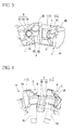
FIG. 3 is an enlarged view showing the periphery of aninsert attachment seat 4, achip pocket 5, and arecessed portion 6 according to the embodiment shown inFIG. 1 when viewed along the central axis of ascrew hole 6C. -
FIG. 4 is an enlarged view showing the periphery of theinsert attachment seat 4, thechip pocket 5, and therecessed portion 6 according to the embodiment shown inFIG. 1 when viewed in a direction parallel to abottom surface 4A of theinsert attachment seat 4 and perpendicular to the central axis of thescrew hole 6C. -
FIG. 5 is a perspective view showing aclamp wedge 10 according to the embodiment of the present invention. -
FIG. 6A is a view showing theclamp wedge 10 according to the embodiment shown inFIG 5 when viewed along the central axis C of ascrew hole 13 in anend surface 12A. -
FIG. 6B is a view showing theclamp wedge 10 according to the embodiment shown inFIG. 5 when viewed in a direction parallel to aclamp surface 14 and perpendicular to the central axis C. -
FIG. 6C is a view showing theclamp wedge 10 according to the embodiment shown inFIG. 5 when viewed in a direction perpendicular to the central axis C and facing theclamp surface 14. -
FIG. 7 is a view showing theclamp wedge 10 according to the embodiment is inserted into the recessedportion 6 shown inFIG. 4 . -
FIG. 8 is a view showing theclamp wedge 10 according to the embodiment is inserted into the recessedportion 6 shown inFIG 3 . -
FIG. 9A is a view showing aclamp wedge 20 according to a modified example of the embodiment shown inFIG. 5 when viewed along the central axis C of thescrew hole 13 in asection 12A. -
FIG. 9B is a view showing theclamp wedge 20 according to the modified example of the embodiment shown inFIG. 5 when viewed in a direction parallel to theclamp surface 14 and perpendicular to the central axis C. -
FIG. 9C is a view showing theclamp wedge 20 according to the modified example of the embodiment shown inFIG 5 when viewed in a direction perpendicular to the central axis C and facing theclamp surface 14. -
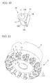
FIG. 10 is a perspective view showing aclamp wedge 30 according to another modified example of the embodiment shown inFIG. 5 . -
FIG. 11 is a perspective view showing the insert-detachable type cutter according to the embodiment of the present invention attached with the cutting insert when viewed from the front-end outer peripheral side of thecutter body 1. -
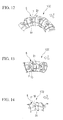
FIG 12 is an enlarged perspective view showing the front-end outer peripheral portion of thecutter body 1 according to the embodiment shown inFIG. 11 when viewed from the front end side thereof. -
FIG. 13 is an enlarged view showing the periphery of achip pocket 5, aclamp wedge 10, aclamp screw 11, and a cuttinginsert 21 according to the embodiment shown inFIG. 11 when viewed along the central axis of theclamp screw 11. -
FIG. 14 is an enlarged view showing the periphery of thechip pocket 5, theclamp wedge 10, theclamp screw 11, and the cuttinginsert 21 according to the embodiment shown inFIG. 11 when viewed in a direction perpendicular to the central axis of theclamp screw 11. -
FIG. 15 is a perspective view showing the cutting insert attached to thecutter body 1 according to the embodiment shown inFIG. 11 . -
FIGS. 1 to 14 are views showing a clamp wedge and an insert-detachable type cutter according to an embodiment of the present invention. In the insert-detachable type cutter according to this embodiment, acutter body 1 is formed of steel or the like so as to have a substantially disc shape as shown inFIG. 1 . The rear end side (the upper side ofFIG. 1 ) of thecutter body 1 in a central axial direction is formed as anattachment portion 2 which is attached to a main shaft of a machine tool. The from end side (the lower side ofFIG. 1 ) of thecutter body 1 is formed as ablade portion 3 having a diameter larger than that of theattachment portion 2 by one level. Thecutter body 1 is configured to rotate about the central axis in a cutter rotation direction T so as to be used in which a workpiece is cut. - The front-end outer peripheral side of the
blade portion 3 is provided with aninsert attachment seat 4 which is formed by cutting the rear-end inner peripheral side of theblade portion 3 so as to fix a cuttinginsert 21 thereto in a seated state as described below. Also, the front-end outer peripheral side thereof is provided with achip pocket 5 and a recessedportion 6 which communicate with each other in theinsert attachment seat 4 in the cutter rotation direction T. Plural groups each including theinsert attachment seat 4, thechip pocket 5, and the recessedportion 6 are arranged in a circumferential direction of theblade portion 3 so as to have a predetermined interval therebetween. Aclamp wedge 10 according to this embodiment is inserted into the recessedportion 6 so as to be pressed toward the rear-end inner peripheral side of thecutter body 1 by means of a clamp screw 11 (pressing member 11) of which both ends are provided with a male screw portion. Accordingly, the cuttinginsert 21 is pressed into theinsert attachment seat 4 so as to be clamp-fixed thereto. -
FIGS. 11 and14 show the insert-detachable type cutter in which each cuttinginsert 21 is accommodated in eachinsert attachment seat 4 and is pressed by eachclamp wedge 10 so as to be clamped thereto. - The cutting insert attached to the insert-detachable type cutter according to this embodiment is formed of a hard material such as hard metal so as to have a regular polygonal (for example, a regular heptagonal) flat plate shape. An example of the cutting insert is shown in
FIG 15 . The cuttinginsert 21 having a flat plate shape shown in this example has a configuration in which both side surfaces are formed parallel to each other in a substantially regular heptagonal shape, one side surface is formed as arake face 23, and then the other side surface is formed as aseat surface 22 facing theinsert attachment seat 4. A cutting blade is formed in a side ridge of the rake face. The cuttinginsert 21 is formed as a hollow insert in which a circular hole is formed in the center of the rake face in a sectional view, and the rake face is formed as a surface having a hole formed therethrough. - The
insert attachment seat 4, on which thehollow cutting insert 21 is seated, includes aflat bottom surface 4A facing the cutter rotation direction T and a pair ofwall surfaces 4B uprightly formed from the side ridges on the inner peripheral side and the rear end side of thecutter body 1 of thebottom surface 4A. Two side surfaces of thehollow insert 21 respectively come into contact with the wall surfaces 4B so as to allow therake face 23 to face the cutter rotation direction T At the same time, theseat surface 22 of the hollow insert comes into close contact with thebottom surface 4A, and the hollow insert is seated in theinsert attachment seat 4. At this time, for example, in the case where the insert-detachable type cutter is a face mill, one of seven cutting blades of the cuttinginsert 21 is located on one plane perpendicular to the central axis of the face mill. - As shown in
FIG. 4 , thechip pocket 5 is formed to be widened toward the outer peripheral side of the cutter body 1 (the upper side ofFIG. 4 ) in the cutter rotation direction T. The recessedportion 6 is opened at the center portion of thebottom surface 5A of thechip pocket 5 facing the outer peripheral side of thecutter body 1 so as to have a gap with respect to the peripheral surface of thecutter body 1. Also, the recessedportion 6 extends to the rear-end inner peripheral side of thecutter body 1 so as to communicate with theinsert attachment seat 4. - The recessed
portion 6 includes abottom surface 6A which is located on the rear-end inner peripheral side of thecutter body 1 and aninner wall surface 6B which extends from thebottom surface 5A of thechip pocket 5 toward thebottom surface 6A and the rear-end inner peripheral side of thecutter body 1. Thebottom surface 6A is provided with ascrew hole 6C into which the male screw portion of one end of theclamp screw 11 is threaded. Thescrew hole 6C faces the rear-end inner peripheral side of thecutter body 1 and thebottom surface 4A of theinsert attachment seat 4 so as to extend in a direction in which the pair ofwall surfaces 4B intersects each other. Theinner wall surface 6B extends in parallel 10 the central axis of thescrew hole 6C. The direction facing the inside (rear-end inner peripheral side) of thecutter body 1 along the central axis of thescrew hole 6C corresponds to the direction in which theclamp wedge 10 according to this embodiment is pressed. The recessedportion 6 is formed in a complementary shape with respect to the shape of theclamp wedge 10. - In the
clamp wedge 10 inserted and pressed into the recessedportion 6, awedge body 12 is formed of steel or the like. As shown inFIGS. 5 and 6A to 6C , theclamp wedge 10 is formed in a hollow piece shape. The hollow portion is formed as ascrew hole 13 into which the male screw portion of the other end of theclamp screw 11 is threaded. Thewedge body 12 is inserted into the recessedportion 6 in such a manner that oneend surface 12A faces the front-end outer peripheral side (front side) of thecutter body 1 and theother end surface 12B faces thebottom surface 6A of the recessedportion 6. Then, theclamp wedge 10 is pressed into the recessedportion 6 in a direction toward the rear-end inner peripheral side of thecutter body 1 by respectively threading the male screw portions of both ends of theclamp screw 11 into thescrew hole 13 of theclamp wedge 10 and thescrew hole 6C. Accordingly, in theclamp wedge 10, the direction from theend surface 12A to theend surface 12B along the central axis C of thescrew hole 13 corresponds to the press-insertion direction. - One of side surfaces extending between both
end surfaces wedge body 12 is formed as aclamp surface 14 which comes into close contact with the rake face of the hollow insert in a direction toward theinsert attachment seat 4 when theclamp wedge 10 is pressed into the recessedportion 6. In this embodiment, aprotrusion 15 is formed at the center of theclamp surface 14. At the boundary between theprotrusion 15 and theclamp surface 14, a recessedgroove portion 14A is formed so as to be slightly recessed from theclamp surface 14. In this embodiment, the whole surface of theclamp surface 14 except for theprotrusion 15 and the recessedgroove portion 14A is formed in an inclined plane shape in which the inclined plane becomes closer to the central axis C of thescrew hole 13 in a direction toward theend surface 12A at an inclined angle formed between the central axis of thescrew hole 6C and thebottom surface 4A of theinsert attachment seat 4. The inclined plane shape is formed so as to surround theprotrusion 15 and the recessedgroove portion 14A. - In addition, in this embodiment, the surface of the
protrusion 15 is formed in a spherical shape. The section taken along theclamp surface 14 and the section parallel to theclamp surface 14 are formed in a circular shape. Here, as shown inFIG. 6 , the protrusion height of theprotrusion 15 from theclamp surface 14 is set to be sufficiently smaller than the radius of the circle formed by theprotrusion 15 in the section taken along theclamp surface 14. At the same time, the radius of the circle in the section is set to be smaller than the radius of the circle formed by the opening of the rake face of the hollow insert. That is, theprotrusion 15 is configured to be accommodated in the hole of the rake face of the hollow insert when theclamp wedge 10 is pressed into the recessedportion 6 so that theclamp surface 14 comes into close contact with the perforated surface of the hollow insert. - On the other hand, the side surface of the
wedge body 12 facing the opposite side of theclamp surface 14 is formed as awedge surface 16. Thewedge surface 16 is formed as a surface (a contact surface in a movable state) which comes into slidable contact with theinner wall surface 6B when theclamp wedge 10 is pressed into the recessedportion 6 of thecutter body 1. Thewedge surface 16 extends in a direction parallel to the central axis C between bothend surfaces wedge surface 16 and theclamp surface 14 so as to be perpendicular to theclamp surface 14 and to be parallel to the central axis C, and theclamp surface 14 is inclined with respect to the central axis C. Accordingly, the width of the side surface becomes narrow in a direction toward theend surface 12B. - In addition, a
protruded curve portion 16A and recessedcurve portions 16B are formed in a section of thewedge surface 16 which is perpendicular to the press-insertion direction. The protrudedcurve portion 16A is a protruded curve portion (barrel roof shape parts or vault shape parts) which forms a protruded curve having a semicircular arc shape (a half of a circular arc) with respect to the central axis C. Each recessedcurve portion 16B is a recessed curve portion which faces theclamp surface 14 and is formed in a recessed curve such as a recessed circular arc which smoothly connects both ends of the protrudedcurve portion 16A to the protrudedcurve portion 16A. The recessedcurve portions 16B widen toward theclamp surface 14 in a direction in which theclamp surface 14 extends in the section. (a vertical direction ofFIG. 6A and a horizontal direction ofFIG 6C ) and is connected to the side surface. Accordingly, in this embodiment, the shape perpendicular to the press-insertion direction of thewedge body 12 is a bell shape shown inFIG. 6A . - In the
clamp wedge 10 according to the present invention, a ratio between the width of the clamp surface (β ofFIG. 6A ) and the diameter (α ofFIG. 6A ) of the semicircular are about the central axis C of the protrudedcurve portion 16A is not limited, but is desirably equal to or more than 60 % and less than 100 %, and more desirably equal to or more than 70 % and equal to or less than 80 %. - The sectional shape of the
inner wall surface 6B of the recessedportion 6 of the cutter body has a ressed-protruded shape opposite to a recessed-protruded shape of thewedge surface 16, theinner wall surface 6B being configured to come into contact with thewedge surface 16 when theclamp wedge 10 is pressed into the recessedportion 6. That is, the sectional shape of theinner wall surface 6B includes a recessed curve portion which forms a recessed curve having a semicircular arc shape (a half of a circular arc) about the central axis of thescrew hole 6C and a protruded curve portion which forms a protruded curve such as a protruded circular arc smoothly connecting both ends of the recessed curve portion to the recessed curve portion so as to be widened in a direction toward theinsert attachment seat 6. - The
bottom surface 5A of thechip pocket 5 of thecutter body 1 is formed in a shape (a recessed surface shape or a bowl shape) which rises up in a direction opposite to the press-insertion direction, thebottom surface 5A corresponding to the periphery of the opening where the recessedportion 6 is opened. That is, in the section perpendicular to the press-insertion direction, that is, the section perpendicular to the central axis of thescrew hole 6C, thebottom surface 5A is formed in a recessed surface shape which rises up in a direction (the front side ofFIGS. 3 and8 ) opposite to the press-insertion direction as the distance from the clampingwedge 10 in a diameter direction of the cutter body becomes greater, that is, thebottom surface 5A toward both ends in an extension direction of theclamp surface 14 of theclamp wedge 10 pressed into the recessedportion 6, or direction toward both sides of thebottom surface 4A of theinsert attachment seat 4 extending in the same section (a vertical direction ofFIGS. 3 and8 ). - In this embodiment, the recessed surface formed by the
bottom surface 5A is formed in a recessed curve surface shape. That is, thebottom surface 5A on the side of the recessedportion 6 is formed in a recessed curve shape in the section including the central axis of thescrew hole 6C and perpendicular to thebottom surface 4A of theinsert attachment seat 4. At the same time, thebottom surface 5A is formed in a recessed curve surface shape which rises up to the front-end outer peripheral side of thecutter body 1 so as to be connected to the peripheral surface of thecutter body 1 as thebottom surface 5A becomes closer to the rear-end outer peripheral side and the front-end inner peripheral side of thecutter body 1 in a direction perpendicular to the plane forming the section (seeFIG. 4 ). - The hollow insert is attached to the insert-detachable type cutter having the above-described configuration, First, the
wedge surface 16 comes into slidable contact with theinner wall surface 6B so as to insert theclamp wedge 10 into the recessedportion 6. Subsequently, theclamp screw 11 is threaded into thescrew hole 13 of thewedge body 12 and thescrew hole 6C of the recessedportion 6 so as to temporarily fix theclamp wedge 10 to thecutter body 1. Subsequently, the hollow insert is seated in theinsert attachment seat 4 as described above. Subsequently, theclamp screw 11 is threaded again so as to press theclamp wedge 10 into the recessedportion 6. At this time, theprotrusion 15 of theclamp wedge 10 is accommodated in the hole of the hollow insert, and theclamp surface 14 comes into close contact with the perforated surface so as to press the hollow insert into thebottom surface 4A of theinsert attachment seat 4. Accordingly, the hollow insert is fixed in a clamped state. In addition, at this time, theprotrusion 15 may come into contact with the opening peripheral edge of the hole so as to draw the hollow insert in a direction in which the pair ofwall surfaces 4B intersects each other. - The
clamp wedge 10 which clamps the hollow insert is formed in a bell shape. That is, the section perpendicular to the press-insertion direction of thewedge body 12 is formed in a bell shape including the protrudedcurve portion 16A in which thewedge surface 16 on the opposite side of theclamp surface 14 forms a protruded curve having a semicircular arc shape and the pair of recessedcurve portions 16B which forms a recessed curve shape from both ends thereof so that the width therebetween becomes large. With such a configuration, it is possible to ensure a large area of theclamp surface 14 without excessively increasing a sectional area of thewedge body 12 and the recessedportion 6 of thecutter body 1, the sectional area being perpendicular to the press-insertion direction. - In the case where such a clamp wedge is used, it is possible to clamp the cutting insert in the larger area. At the same time, it is possible to improve the attaching rigidity of the
clamp wedge 10 by enlarging the distance between the surface of thecutter body 1 and theinner wall surface 6B of the recessedportion 6. Accordingly, it is possible to improve the clamping strength of the hollow insert and thus to highly precisely carry out the cutting process in a stable manner. In addition, since the sectional area of the recessedportion 6 does not excessively increases, it is possible to cope with an increase in the number of blades of thecutter body 1. Accordingly, since deformation or damage does not occur in thecutter body 1 during a clamping operation even when the number of blades increases, it is possible to reliably carry out the efficient cutting process by means of plural blades. - Particularly, in this embodiment, the region from the protruded
curve portion 16A to the recessedcurve portions 6B of both ends thereof is formed as thewedge surface 16 as described above. In addition, each recessedcurve portion 16B is inclined in a direction from theend surface 12A of thewedge body 12 to theend surface 12B, that is, the press-insertion direction so that a gap between itself and theclamp surface 14 becomes small. Accordingly, it is possible to reliably apply the pressing force to both widened side portions of theclamp surface 14 on the under side of the recessedcurve portion 16B. Accordingly, it is possible to further strongly clamp-fix the cutting insert, and thus to highly precisely carry out the cutting process in a stabler manner. - Meanwhile, in the insert-detachable type cutter according to this embodiment, the
bottom surface 5A of thechip pocket 5 is formed in a recessed surface shape, thebottom surface 5A corresponding to the periphery of the opening where the recessedportion 6 of thecutter body 1 is opened. That is, in a section perpendicular to the press-insertion, direction, thebottom surface 5A is formed in a recessed surface shape which rises up in a direction opposite to the press-insertion direction as the distance from the clampingwedge 10 in a diameter direction of the cutter body becomes greater. For this reason, even when the gap between groups each having theinsert attachment seat 4, thechip pocket 5, and the recessedportion 6 is limited to be small due to an increase in the number of blades, it is possible to ensure a large thickness of thecutter body 1 in the periphery of the recessedportion 6. Accordingly, it is possible to improve the rigidity in the periphery of the recessedportion 6. As a result, it is possible to strongly carry out the insert attaching operation in a stable manner by reliably ensuring the clamping strength. - In the recessed surface formed by the
bottom surface 5A of thechip pocket 5, for example, a section perpendicular to the plane including the central axis of thescrew hole 6C and perpendicular to thebottom surface 4A of theinsert attachment seat 4 may be formed in a V-shape. In this embodiment, in the same section, thebottom surface 5A on the side of the recessedportion 6 forms the most recessed curve so as to rises up in a direction opposite to the press-insertion diction as the distance from the clamping wedge (10, 20, 30) in a diameter direction of the cutter body becomes greater, that is, toward the rear-end outer peripheral side and the front-end inner peripheral side of thecutter body 1. With such a configuration, it is possible to increase the capacity of thechip pocket 5 compared with the case where the section is formed in a V-shape as described above. Accordingly, in the insert-detachable type cutter according to this embodiment, it is possible to reliably accommodate small fragments produced by the cutting blade of the cutting insert in thechip pocket 5 and to smoothly discharge the small fragments. That is, in the insext-detachable type cutter according to this embodiment, it is possible to efficiently carry out the cutting process in a mare stable manner. - Further in the
clamp wedge 10 according to this embodiment, theclamp surface 14 is provided with theprotrusion 15 which is accommodated in the hole of the hollow insert. Upon performing a corner change operation of the insert due to the abrasion of the cutting blade after the clamped hollow insert is used for a cutting process, first, theclamp screw 11 is slightly loosened so as to release the pressed stale of the hollow insert. Subsequently, in the range that theprotrusion 15 is accommodated in the hole of thehollow insert 21 so as to maintain the engagement therebetween, theclamp wedge 10 and the hollow insert are drawn out to the rear side in the press-insertion direction so as to deviate from each other. At this time, the hollow insert engages with theprotrusion 5 so as to be rotatable about theprotrusion 15 while being prevented from separating from theinsert attachment seat 4. - Subsequently, in this state, the hollow insert is rotated so that the cutting blade to be used faces a predetemimed direction. Subsequently, the insert is seated again in the
insert attachment seat 4, and is clamped by threading theclamp screw 11 thereinto. Accordingly, for example, even when the insert-detachable type cutter is a face mill or the like and is mounted to a main shaft of a machine tool so that theinsert attachment seat 4 faces downward, it is possible to carry out the corner change operation without dropping the hollow insert. For this reason, in theclamp wedge 10 and the insert-detachable type cutter according to this embodiment, an operator does not have to rotate the inserts individually while pressing the insert by hand so as not to be dropped or an operator does not have to separate thecutter body 1 from the main shaft so as to carry out the corner change operation. Accordingly. even when the cutter bas a plural of blades, inserts, and clampwedges 10, it is possible to easily carry out the corner change operation in a short amount of time and to promptly resume the cutting process. As a result it is possible to improve the working efficiency or the economical efficiency by shortening the overall processing time. - In addition, in this embodiment, since the
protrusion 15 is formed in a spherical shape, theprotrusion 15 is not crushed even when the corner change operation is repeated. At the same time, in this embodiment, it is possible to ensure a large gap between the hole and the protrusion in such a manner that theclamp wedge 10 is made to recede along theinner wall surface 6B of the recessedportion 6 as described above so as to have a slight gap between theclamp surface 14 and the perforated surface of the hollow insert. Accordingly, since the insert is easily rotated, it is further possible to simply carry out the corner change operation. - The
protrusion 15 may be formed in a shape in which the corner change operation can be carried out by blowing the hollow insert to be rotatable about theprotrusion 15 when theclamp wedge 10 and the hollow insert are drawn out to the rear side in the press-insertion direction in a range that the engagement between theprotrusion 15 and the hole is maintained. For example, theprotrusion 15 may be formed in a conical shape or a conical trapezoid shape. In addiction, the hollow insert may not be formed in a regular polygonal flat plate shape so long as the side ridge of the surface having a hole formed therethrough is provided with plural cutting blades of which the corners can be changed. For example, the hollow insert may be as a disc-shaped hollow insert. In addition, the hole of the hollow insert may be a perforation hole which is formed through the surface having the hole and the opposite surface thereof. Alternatively, the hole may not be a perforation hole. - Incidentally, in the
clamp wedge 10 according to this embodiment, the periphery of theprotrusion 15 is surrounded by theclamp surface 14 via the recessedgroove portion 14A. For example, like aclamp wedge 20 according to a modified example shown inFIG. 9 , the recessedgroove portion 14A may extend to the edge of theclamp surface 14 so as to be opened from the edge. In addiction, in the modified example shown inFIG. 9 or another modified example shown inFIG. 10 described below, the same reference numerals are given to the same parts as those of theclamp wedge 10 according to the above-described embodiment, and the description thereof will be omitted. - In the case where the recessed
groove portion 14A is formed like a modified example shown in FTG. 9, theclamp surface 14 is formed in a U-shape as shown inFIG. 9C . Accordingly, it is possible to carry out a finishing process in such a manner that a finishing tool such as a grinding tool or a finishing end mill used upon smoothly finishing theclamp surface 14 moves once along the U-shape without a locus overlap. That is, in a portion where the finishing tool advances to theclamp surface 14 and a portion where the finishing tool recedes from theclamp surface 14, the finishing surfaces thereof do not overlap with each other. Accordingly, it is possible to reliably allow theclamp surface 14 to come into close contact with the perforated surface of the hollow insert without a minute step formed between, the finishing surfaces in the overlapping portions. - However, in the clamp wedge and the insert-detachable type cutter according to the invention, the
protrusion 15 or the recessedgroove portion 14A may not be formed in theclamp surface 14. That is, like theclamp wedge 30 according to another modified example shown inFIG. 10 , thewhole clamp surface 14 may be formed in a plane shape in which a gap between theclamp surface 14 and thewedge surface 16 becomes small in the press-insertion direction. According to theclamp wedge 30, it is possible to carry out the clamping operation in a stable manner by further enlarging the contact area between theclamp surface 14 and the cutting insert, and to clamp the cutting insert without a hole instead of the hollow insert.
In theclamp wedge 10 of the above embodiments, the protrudedcurve portion 16A of thewedge surface 16 has a semicircular shape in a cross section perpendicular to the central axis C. The protrudedcurve portion 16A may be formed a arc shape having a central angle less than 180° with respect to the central axis C, for example, the central angle may be 45°or the like. In addition, the protruded curve need not be formed the are shape, the protruded curve may have an elliptical-shaped cross section. - While preferred embodiment of the present invention have been described and illustrated above, it should he understood that these are exemplary of the present invention and are not to be considered as limiting. Additions, omissions, substitutions, and other modifications can be made without departing from the spirit or scope of the present invention. Accordingly, the present invention is not to be considered as being limited by the foregoing description, and is only limited by the scope of the appended claims.
Claims (5)
- An insert clamping wedge (10, 20, 30) for clamp-fixing a cutting insert (21), seated in an insert attachment seat (4) formed in a cutter body (1), to a recessed portion (6) formed in the insert attachment seat (4), the insert clamping wedge (10, 20, 30) comprising;a wedge body (12),wherein the insert clamping wedge (10, 20, 30) is pressed into the cutter body (1),wherein the wedge body (12) includes a clamp surface (14) which comes into close contact with the cutting insert (21) and a wedge surface (16) of which a gap between the wedge surface (16) and the clamp surface (14) becomes smaller in a press-insertion direction of the wedge body (12), andwherein an external shape of the wedge surface in a section perpendicular to the press-insertion direction of the wedge body (12) includes a protruded curve portion (16A) and a distance between recessed curve portions (16B) of which a width becomes larger in a direction from both ends of the protruded curve portion toward the clamp surface, the section from the wedge surface (14) to the clamp surface being formed in a bell shape.
- The insert clamping wedge according to Claim 1, wherein in the section perpendicular to the press-insertion direction of the wedge body (12), the wedge surface (16) is formed by a region from the protruded curve portion (16A) to at least the recessed curve portions (16B) in both ends thereof.
- An insert-detachable type cutter comprising:a circular cutter body (1) provided with recessed insert attachment seats (4) which are formed in a circumferential direction at a predetermined interval so as to respectively seat (4) cutting inserts therein and a recessed portion (6) which, is formed adjacent to each insert attachment seat (4);an insert clamping wedge (10, 20, 30) which is accommodated in each recessed portion (6) and is pressed into a bottom of the recessed portion (6) so as to press-fix the cutting insert to the insert attachment seat (4); anda pressing member (11) which presses the insert clamping wedge (10, 20, 30) into the bottom of the recessed portion (6),wherein the insert clamping wedge (10, 20, 30) is the insert clamping wedge according to Claim 1 or 2, andwherein the recessed portion (6) is formed in a complementary shape with respect to the shape of the insert clamping wedge (10, 20, 30).
- The insert-detachable type cutter according to Claim 3, wherein in a section perpendicular to the press-insertion direction, each of opening peripheries of the recessed portion (6) of the cutter body (1) are formed in a recessed surface which rises up in a direction opposite to the press-insertion direction as the distance from the clamping wedge (10, 20, 3 0) in a diameter direction of the cutter body becomes greater.
- The insen-detachable type cutter according to Claim 4, wherein the opening periphery of the recessed portion (6) is formed in a recessed curve surface shape.
Applications Claiming Priority (1)
| Application Number | Priority Date | Filing Date | Title |
|---|---|---|---|
| JP2008088334 | 2008-03-28 |
Publications (2)
| Publication Number | Publication Date |
|---|---|
| EP2105230A1 true EP2105230A1 (en) | 2009-09-30 |
| EP2105230B1 EP2105230B1 (en) | 2014-01-15 |
Family
ID=40823326
Family Applications (1)
| Application Number | Title | Priority Date | Filing Date |
|---|---|---|---|
| EP09156280.1A Active EP2105230B1 (en) | 2008-03-28 | 2009-03-26 | Insert clamping wedge and insert-detachable type cutter |
Country Status (5)
| Country | Link |
|---|---|
| US (2) | US7909543B2 (en) |
| EP (1) | EP2105230B1 (en) |
| JP (1) | JP5338425B2 (en) |
| KR (1) | KR101520974B1 (en) |
| CN (1) | CN101543906B (en) |
Cited By (1)
| Publication number | Priority date | Publication date | Assignee | Title |
|---|---|---|---|---|
| DE102022213281A1 (en) * | 2022-12-08 | 2024-06-13 | Kennametal Inc. | Rotary tool, especially milling cutters |
Families Citing this family (9)
| Publication number | Priority date | Publication date | Assignee | Title |
|---|---|---|---|---|
| US9205499B2 (en) | 2013-09-11 | 2015-12-08 | Kennametal Inc. | Cutting insert with finishing and roughing cutting edges |
| US9211590B2 (en) * | 2013-09-20 | 2015-12-15 | Kennametal Inc. | Screw head wedge clamp assembly for cutting tool |
| US9211589B2 (en) | 2013-10-08 | 2015-12-15 | Kennametal Inc. | Double-sided, nonagon cutting insert |
| US9475138B2 (en) | 2014-01-22 | 2016-10-25 | Kennametal Inc. | Cutting tool having insert pocket with cantilevered member |
| US10357859B1 (en) | 2014-03-06 | 2019-07-23 | Daniel J Reed | Clamping system for securing a work piece to a fixture |
| EP3195971B1 (en) * | 2014-08-27 | 2024-04-03 | Kyocera Corporation | Cutting insert, cutting tool, and method for manufacturing cut product |
| ES2616111B1 (en) * | 2016-10-28 | 2018-01-19 | Herramientas Preziss, S.L. | INSERT ANCHORING SYSTEM FOR MACHINING OF PARTS |
| CN107199363B (en) * | 2017-07-12 | 2023-10-27 | 北京沃尔德金刚石工具股份有限公司 | A face milling cutter head and a face milling cutter using the same |
| DE102022104671A1 (en) * | 2022-02-28 | 2023-08-31 | Gühring KG | Clamping device for clamping a cutting tool in a tool carrier |
Citations (4)
| Publication number | Priority date | Publication date | Assignee | Title |
|---|---|---|---|---|
| JPH0144443B2 (en) | 1980-05-07 | 1989-09-27 | Kaaboroi Inc | |
| JPH01295709A (en) | 1988-03-11 | 1989-11-29 | Sandvik Ab | Milling cutter |
| US20070256287A1 (en) | 2006-05-03 | 2007-11-08 | Valenite Llc | Cutting tool with adjustable indexable cutting insert |
| WO2008023361A1 (en) | 2006-08-21 | 2008-02-28 | Iscar Ltd. | Cutting insert adjustment device |
Family Cites Families (15)
| Publication number | Priority date | Publication date | Assignee | Title |
|---|---|---|---|---|
| US3481015A (en) * | 1967-07-19 | 1969-12-02 | Gerald Q Bogner | Rotary cutting tool |
| US3566496A (en) * | 1968-06-03 | 1971-03-02 | Precision Industries | Form tool |
| US3660879A (en) * | 1970-01-19 | 1972-05-09 | Ingersoll Milling Machine Co | Cutter with nested indexable blade clamped by screw actuated wedge |
| US3624879A (en) * | 1970-01-19 | 1971-12-07 | Ingersoll Milling Machine Co | Cutter with nested indexable blade clamped by screw actuated wedge |
| US4311418A (en) * | 1980-06-24 | 1982-01-19 | General Electric Company | Adjustable axial and radial locating wedge assemblies for an indexable insert cutting tool |
| CN86203635U (en) * | 1986-06-05 | 1987-06-17 | 项斯璋 | Clip-on carbide cylindric milling cutter |
| JP2607746B2 (en) * | 1990-10-04 | 1997-05-07 | 住友電気工業株式会社 | Indexable cutter |
| DE4034345C1 (en) * | 1990-10-29 | 1991-08-29 | Mapal Fabrik Fuer Praezisionswerkzeuge Dr. Kress Kg, 7080 Aalen, De | |
| US5775854A (en) * | 1991-09-27 | 1998-07-07 | Iscar Ltd. | Metal cutting tool |
| JP3264540B2 (en) * | 1993-01-13 | 2002-03-11 | ダイジ▲ェ▼ット工業株式会社 | Rotary cutting tool |
| GB9304838D0 (en) * | 1993-03-09 | 1993-04-28 | Hydra Tools Int Plc | Rotary metal cutting tool |
| US5542794A (en) * | 1994-11-09 | 1996-08-06 | Kennametal Inc. | Multi-handed milling cutter having indexable wedges and inserts |
| SE9503867D0 (en) * | 1995-11-02 | 1995-11-02 | Sandvik Ab | Milling Tools |
| DE19725219C2 (en) * | 1997-06-15 | 1999-05-20 | Walter Ag | Milling tool with axial adjustment of the insert seat |
| CN200948512Y (en) * | 2006-09-25 | 2007-09-19 | 黄钲原 | Improved structure of side milling cutter |
-
2009
- 2009-03-26 JP JP2009077336A patent/JP5338425B2/en active Active
- 2009-03-26 US US12/411,508 patent/US7909543B2/en active Active
- 2009-03-26 EP EP09156280.1A patent/EP2105230B1/en active Active
- 2009-03-26 KR KR1020090025902A patent/KR101520974B1/en active Active
- 2009-03-30 CN CN2009101302826A patent/CN101543906B/en active Active
-
2011
- 2011-02-14 US US13/026,445 patent/US7997833B2/en active Active
Patent Citations (4)
| Publication number | Priority date | Publication date | Assignee | Title |
|---|---|---|---|---|
| JPH0144443B2 (en) | 1980-05-07 | 1989-09-27 | Kaaboroi Inc | |
| JPH01295709A (en) | 1988-03-11 | 1989-11-29 | Sandvik Ab | Milling cutter |
| US20070256287A1 (en) | 2006-05-03 | 2007-11-08 | Valenite Llc | Cutting tool with adjustable indexable cutting insert |
| WO2008023361A1 (en) | 2006-08-21 | 2008-02-28 | Iscar Ltd. | Cutting insert adjustment device |
Cited By (1)
| Publication number | Priority date | Publication date | Assignee | Title |
|---|---|---|---|---|
| DE102022213281A1 (en) * | 2022-12-08 | 2024-06-13 | Kennametal Inc. | Rotary tool, especially milling cutters |
Also Published As
| Publication number | Publication date |
|---|---|
| US7909543B2 (en) | 2011-03-22 |
| US20090245951A1 (en) | 2009-10-01 |
| CN101543906A (en) | 2009-09-30 |
| KR20090103794A (en) | 2009-10-01 |
| EP2105230B1 (en) | 2014-01-15 |
| KR101520974B1 (en) | 2015-05-15 |
| JP5338425B2 (en) | 2013-11-13 |
| CN101543906B (en) | 2012-11-14 |
| US20110135409A1 (en) | 2011-06-09 |
| JP2009255287A (en) | 2009-11-05 |
| US7997833B2 (en) | 2011-08-16 |
Similar Documents
| Publication | Publication Date | Title |
|---|---|---|
| US7997833B2 (en) | Insert clamping wedge and insert-detachable type cutter | |
| CN101977714B (en) | Radius end mill and cutting insert | |
| JP5357202B2 (en) | Cutting insert, milling tool equipped with the same, and cutting method using the same | |
| CN108602130B (en) | Face grooving tool body for metal cutting | |
| EP2298479B1 (en) | Method for temporal fixing of a tip to a cutting tool | |
| KR20110070802A (en) | Face mills for fine milling | |
| EP3241638B1 (en) | Cutting insert, tool body, and cutting tool | |
| US8943933B2 (en) | Cutting edge replacement type groove forming tool and end face groove forming method | |
| EP2567768A1 (en) | Cutting insert, and blade tip replacement type cutting tool | |
| CN101164726A (en) | Radius End Mills | |
| JP4729894B2 (en) | Insert and throw-away cutting tools | |
| WO2019235084A1 (en) | Cutting insert and cutting edge replacement type cutting tool | |
| JP6852258B2 (en) | Cutting inserts and cutting tools with replaceable cutting edges | |
| JP2022528089A (en) | Milling head and ball end mill | |
| CN111448021A (en) | High speed feed severing blade for narrow width severing operations | |
| JP5315749B2 (en) | Insert detachable cutter | |
| JP4952560B2 (en) | Throw-away face mill | |
| JP2007260788A (en) | Cutting insert and cutting tool | |
| JP2008100316A (en) | Cutting tools and finishing blade inserts | |
| JP5233362B2 (en) | Insert clamp wedge and insert detachable cutter | |
| JP2020116707A (en) | Indexable End Mill | |
| KR20210063501A (en) | End mill | |
| JP2002326115A (en) | Indexable end mills for secondary machining | |
| JP2012152868A (en) | Cutting insert and cutting edge change type cutting tool |
Legal Events
| Date | Code | Title | Description |
|---|---|---|---|
| PUAI | Public reference made under article 153(3) epc to a published international application that has entered the european phase |
Free format text: ORIGINAL CODE: 0009012 |
|
| AK | Designated contracting states |
Kind code of ref document: A1 Designated state(s): AT BE BG CH CY CZ DE DK EE ES FI FR GB GR HR HU IE IS IT LI LT LU LV MC MK MT NL NO PL PT RO SE SI SK TR |
|
| AX | Request for extension of the european patent |
Extension state: AL BA RS |
|
| 17P | Request for examination filed |
Effective date: 20100329 |
|
| AKX | Designation fees paid |
Designated state(s): AT BE BG CH CY CZ DE DK EE ES FI FR GB GR HR HU IE IS IT LI LT LU LV MC MK MT NL NO PL PT RO SE SI SK TR |
|
| 17Q | First examination report despatched |
Effective date: 20101210 |
|
| GRAP | Despatch of communication of intention to grant a patent |
Free format text: ORIGINAL CODE: EPIDOSNIGR1 |
|
| INTG | Intention to grant announced |
Effective date: 20130829 |
|
| GRAS | Grant fee paid |
Free format text: ORIGINAL CODE: EPIDOSNIGR3 |
|
| GRAA | (expected) grant |
Free format text: ORIGINAL CODE: 0009210 |
|
| AK | Designated contracting states |
Kind code of ref document: B1 Designated state(s): AT BE BG CH CY CZ DE DK EE ES FI FR GB GR HR HU IE IS IT LI LT LU LV MC MK MT NL NO PL PT RO SE SI SK TR |
|
| REG | Reference to a national code |
Ref country code: GB Ref legal event code: FG4D Ref country code: CH Ref legal event code: EP |
|
| REG | Reference to a national code |
Ref country code: AT Ref legal event code: REF Ref document number: 649563 Country of ref document: AT Kind code of ref document: T Effective date: 20140215 |
|
| REG | Reference to a national code |
Ref country code: IE Ref legal event code: FG4D |
|
| REG | Reference to a national code |
Ref country code: DE Ref legal event code: R096 Ref document number: 602009021428 Country of ref document: DE Effective date: 20140227 |
|
| REG | Reference to a national code |
Ref country code: SE Ref legal event code: TRGR |
|
| REG | Reference to a national code |
Ref country code: NL Ref legal event code: VDEP Effective date: 20140115 |
|
| REG | Reference to a national code |
Ref country code: AT Ref legal event code: MK05 Ref document number: 649563 Country of ref document: AT Kind code of ref document: T Effective date: 20140115 |
|
| REG | Reference to a national code |
Ref country code: LT Ref legal event code: MG4D |
|
| PG25 | Lapsed in a contracting state [announced via postgrant information from national office to epo] |
Ref country code: IS Free format text: LAPSE BECAUSE OF FAILURE TO SUBMIT A TRANSLATION OF THE DESCRIPTION OR TO PAY THE FEE WITHIN THE PRESCRIBED TIME-LIMIT Effective date: 20140515 Ref country code: LT Free format text: LAPSE BECAUSE OF FAILURE TO SUBMIT A TRANSLATION OF THE DESCRIPTION OR TO PAY THE FEE WITHIN THE PRESCRIBED TIME-LIMIT Effective date: 20140115 Ref country code: NO Free format text: LAPSE BECAUSE OF FAILURE TO SUBMIT A TRANSLATION OF THE DESCRIPTION OR TO PAY THE FEE WITHIN THE PRESCRIBED TIME-LIMIT Effective date: 20140415 |
|
| PG25 | Lapsed in a contracting state [announced via postgrant information from national office to epo] |
Ref country code: AT Free format text: LAPSE BECAUSE OF FAILURE TO SUBMIT A TRANSLATION OF THE DESCRIPTION OR TO PAY THE FEE WITHIN THE PRESCRIBED TIME-LIMIT Effective date: 20140115 Ref country code: FI Free format text: LAPSE BECAUSE OF FAILURE TO SUBMIT A TRANSLATION OF THE DESCRIPTION OR TO PAY THE FEE WITHIN THE PRESCRIBED TIME-LIMIT Effective date: 20140115 Ref country code: NL Free format text: LAPSE BECAUSE OF FAILURE TO SUBMIT A TRANSLATION OF THE DESCRIPTION OR TO PAY THE FEE WITHIN THE PRESCRIBED TIME-LIMIT Effective date: 20140115 Ref country code: ES Free format text: LAPSE BECAUSE OF FAILURE TO SUBMIT A TRANSLATION OF THE DESCRIPTION OR TO PAY THE FEE WITHIN THE PRESCRIBED TIME-LIMIT Effective date: 20140115 Ref country code: CY Free format text: LAPSE BECAUSE OF FAILURE TO SUBMIT A TRANSLATION OF THE DESCRIPTION OR TO PAY THE FEE WITHIN THE PRESCRIBED TIME-LIMIT Effective date: 20140115 Ref country code: PT Free format text: LAPSE BECAUSE OF FAILURE TO SUBMIT A TRANSLATION OF THE DESCRIPTION OR TO PAY THE FEE WITHIN THE PRESCRIBED TIME-LIMIT Effective date: 20140515 |
|
| PG25 | Lapsed in a contracting state [announced via postgrant information from national office to epo] |
Ref country code: HR Free format text: LAPSE BECAUSE OF FAILURE TO SUBMIT A TRANSLATION OF THE DESCRIPTION OR TO PAY THE FEE WITHIN THE PRESCRIBED TIME-LIMIT Effective date: 20140115 Ref country code: LV Free format text: LAPSE BECAUSE OF FAILURE TO SUBMIT A TRANSLATION OF THE DESCRIPTION OR TO PAY THE FEE WITHIN THE PRESCRIBED TIME-LIMIT Effective date: 20140115 Ref country code: BE Free format text: LAPSE BECAUSE OF FAILURE TO SUBMIT A TRANSLATION OF THE DESCRIPTION OR TO PAY THE FEE WITHIN THE PRESCRIBED TIME-LIMIT Effective date: 20140115 |
|
| REG | Reference to a national code |
Ref country code: DE Ref legal event code: R097 Ref document number: 602009021428 Country of ref document: DE |
|
| PG25 | Lapsed in a contracting state [announced via postgrant information from national office to epo] |
Ref country code: CZ Free format text: LAPSE BECAUSE OF FAILURE TO SUBMIT A TRANSLATION OF THE DESCRIPTION OR TO PAY THE FEE WITHIN THE PRESCRIBED TIME-LIMIT Effective date: 20140115 Ref country code: RO Free format text: LAPSE BECAUSE OF FAILURE TO SUBMIT A TRANSLATION OF THE DESCRIPTION OR TO PAY THE FEE WITHIN THE PRESCRIBED TIME-LIMIT Effective date: 20140115 Ref country code: EE Free format text: LAPSE BECAUSE OF FAILURE TO SUBMIT A TRANSLATION OF THE DESCRIPTION OR TO PAY THE FEE WITHIN THE PRESCRIBED TIME-LIMIT Effective date: 20140115 Ref country code: LU Free format text: LAPSE BECAUSE OF FAILURE TO SUBMIT A TRANSLATION OF THE DESCRIPTION OR TO PAY THE FEE WITHIN THE PRESCRIBED TIME-LIMIT Effective date: 20140326 Ref country code: DK Free format text: LAPSE BECAUSE OF FAILURE TO SUBMIT A TRANSLATION OF THE DESCRIPTION OR TO PAY THE FEE WITHIN THE PRESCRIBED TIME-LIMIT Effective date: 20140115 |
|
| REG | Reference to a national code |
Ref country code: CH Ref legal event code: PL |
|
| PLBE | No opposition filed within time limit |
Free format text: ORIGINAL CODE: 0009261 |
|
| STAA | Information on the status of an ep patent application or granted ep patent |
Free format text: STATUS: NO OPPOSITION FILED WITHIN TIME LIMIT |
|
| PG25 | Lapsed in a contracting state [announced via postgrant information from national office to epo] |
Ref country code: PL Free format text: LAPSE BECAUSE OF FAILURE TO SUBMIT A TRANSLATION OF THE DESCRIPTION OR TO PAY THE FEE WITHIN THE PRESCRIBED TIME-LIMIT Effective date: 20140115 Ref country code: SK Free format text: LAPSE BECAUSE OF FAILURE TO SUBMIT A TRANSLATION OF THE DESCRIPTION OR TO PAY THE FEE WITHIN THE PRESCRIBED TIME-LIMIT Effective date: 20140115 |
|
| 26N | No opposition filed |
Effective date: 20141016 |
|
| REG | Reference to a national code |
Ref country code: IE Ref legal event code: MM4A |
|
| PG25 | Lapsed in a contracting state [announced via postgrant information from national office to epo] |
Ref country code: CH Free format text: LAPSE BECAUSE OF NON-PAYMENT OF DUE FEES Effective date: 20140331 Ref country code: LI Free format text: LAPSE BECAUSE OF NON-PAYMENT OF DUE FEES Effective date: 20140331 Ref country code: IE Free format text: LAPSE BECAUSE OF NON-PAYMENT OF DUE FEES Effective date: 20140326 |
|
| REG | Reference to a national code |
Ref country code: DE Ref legal event code: R097 Ref document number: 602009021428 Country of ref document: DE Effective date: 20141016 |
|
| PG25 | Lapsed in a contracting state [announced via postgrant information from national office to epo] |
Ref country code: SI Free format text: LAPSE BECAUSE OF FAILURE TO SUBMIT A TRANSLATION OF THE DESCRIPTION OR TO PAY THE FEE WITHIN THE PRESCRIBED TIME-LIMIT Effective date: 20140115 |
|
| PG25 | Lapsed in a contracting state [announced via postgrant information from national office to epo] |
Ref country code: MT Free format text: LAPSE BECAUSE OF FAILURE TO SUBMIT A TRANSLATION OF THE DESCRIPTION OR TO PAY THE FEE WITHIN THE PRESCRIBED TIME-LIMIT Effective date: 20140115 |
|
| REG | Reference to a national code |
Ref country code: FR Ref legal event code: PLFP Year of fee payment: 8 |
|
| PG25 | Lapsed in a contracting state [announced via postgrant information from national office to epo] |
Ref country code: MC Free format text: LAPSE BECAUSE OF FAILURE TO SUBMIT A TRANSLATION OF THE DESCRIPTION OR TO PAY THE FEE WITHIN THE PRESCRIBED TIME-LIMIT Effective date: 20140115 |
|
| PG25 | Lapsed in a contracting state [announced via postgrant information from national office to epo] |
Ref country code: GR Free format text: LAPSE BECAUSE OF FAILURE TO SUBMIT A TRANSLATION OF THE DESCRIPTION OR TO PAY THE FEE WITHIN THE PRESCRIBED TIME-LIMIT Effective date: 20140416 Ref country code: BG Free format text: LAPSE BECAUSE OF FAILURE TO SUBMIT A TRANSLATION OF THE DESCRIPTION OR TO PAY THE FEE WITHIN THE PRESCRIBED TIME-LIMIT Effective date: 20140115 Ref country code: IT Free format text: LAPSE BECAUSE OF FAILURE TO SUBMIT A TRANSLATION OF THE DESCRIPTION OR TO PAY THE FEE WITHIN THE PRESCRIBED TIME-LIMIT Effective date: 20140115 |
|
| PG25 | Lapsed in a contracting state [announced via postgrant information from national office to epo] |
Ref country code: TR Free format text: LAPSE BECAUSE OF FAILURE TO SUBMIT A TRANSLATION OF THE DESCRIPTION OR TO PAY THE FEE WITHIN THE PRESCRIBED TIME-LIMIT Effective date: 20140115 Ref country code: HU Free format text: LAPSE BECAUSE OF FAILURE TO SUBMIT A TRANSLATION OF THE DESCRIPTION OR TO PAY THE FEE WITHIN THE PRESCRIBED TIME-LIMIT; INVALID AB INITIO Effective date: 20090326 |
|
| REG | Reference to a national code |
Ref country code: FR Ref legal event code: PLFP Year of fee payment: 9 |
|
| PGFP | Annual fee paid to national office [announced via postgrant information from national office to epo] |
Ref country code: FR Payment date: 20170322 Year of fee payment: 9 Ref country code: SE Payment date: 20170321 Year of fee payment: 9 |
|
| PGFP | Annual fee paid to national office [announced via postgrant information from national office to epo] |
Ref country code: GB Payment date: 20170322 Year of fee payment: 9 |
|
| PG25 | Lapsed in a contracting state [announced via postgrant information from national office to epo] |
Ref country code: MK Free format text: LAPSE BECAUSE OF FAILURE TO SUBMIT A TRANSLATION OF THE DESCRIPTION OR TO PAY THE FEE WITHIN THE PRESCRIBED TIME-LIMIT Effective date: 20140115 |
|
| PG25 | Lapsed in a contracting state [announced via postgrant information from national office to epo] |
Ref country code: SE Free format text: LAPSE BECAUSE OF NON-PAYMENT OF DUE FEES Effective date: 20180327 |
|
| GBPC | Gb: european patent ceased through non-payment of renewal fee |
Effective date: 20180326 |
|
| PG25 | Lapsed in a contracting state [announced via postgrant information from national office to epo] |
Ref country code: GB Free format text: LAPSE BECAUSE OF NON-PAYMENT OF DUE FEES Effective date: 20180326 |
|
| PG25 | Lapsed in a contracting state [announced via postgrant information from national office to epo] |
Ref country code: FR Free format text: LAPSE BECAUSE OF NON-PAYMENT OF DUE FEES Effective date: 20180331 |
|
| PGFP | Annual fee paid to national office [announced via postgrant information from national office to epo] |
Ref country code: DE Payment date: 20260319 Year of fee payment: 18 |