EP2104926B1 - Displaying elevation information from a digital map - Google Patents
Displaying elevation information from a digital map Download PDFInfo
- Publication number
- EP2104926B1 EP2104926B1 EP08701086A EP08701086A EP2104926B1 EP 2104926 B1 EP2104926 B1 EP 2104926B1 EP 08701086 A EP08701086 A EP 08701086A EP 08701086 A EP08701086 A EP 08701086A EP 2104926 B1 EP2104926 B1 EP 2104926B1
- Authority
- EP
- European Patent Office
- Prior art keywords
- shading
- elevation
- function
- information
- display
- Prior art date
- Legal status (The legal status is an assumption and is not a legal conclusion. Google has not performed a legal analysis and makes no representation as to the accuracy of the status listed.)
- Active
Links
- 238000000034 method Methods 0.000 claims abstract description 32
- 238000009877 rendering Methods 0.000 claims abstract description 16
- 230000006870 function Effects 0.000 claims description 57
- 238000004422 calculation algorithm Methods 0.000 claims description 12
- 238000004590 computer program Methods 0.000 claims 1
- 238000013459 approach Methods 0.000 description 6
- 238000012545 processing Methods 0.000 description 6
- 238000004364 calculation method Methods 0.000 description 4
- 230000008859 change Effects 0.000 description 4
- 230000007704 transition Effects 0.000 description 4
- 230000001419 dependent effect Effects 0.000 description 3
- 239000011159 matrix material Substances 0.000 description 3
- 238000012935 Averaging Methods 0.000 description 2
- 230000000694 effects Effects 0.000 description 2
- 230000003068 static effect Effects 0.000 description 2
- 230000003044 adaptive effect Effects 0.000 description 1
- 230000004075 alteration Effects 0.000 description 1
- 239000003086 colorant Substances 0.000 description 1
- 238000007796 conventional method Methods 0.000 description 1
- 230000003247 decreasing effect Effects 0.000 description 1
- 238000010586 diagram Methods 0.000 description 1
- 238000007620 mathematical function Methods 0.000 description 1
- 238000012986 modification Methods 0.000 description 1
- 230000004048 modification Effects 0.000 description 1
- 230000003287 optical effect Effects 0.000 description 1
- 230000008569 process Effects 0.000 description 1
- 238000005070 sampling Methods 0.000 description 1
- 239000004065 semiconductor Substances 0.000 description 1
Images


Classifications
-
- G—PHYSICS
- G06—COMPUTING; CALCULATING OR COUNTING
- G06T—IMAGE DATA PROCESSING OR GENERATION, IN GENERAL
- G06T17/00—Three dimensional [3D] modelling, e.g. data description of 3D objects
- G06T17/05—Geographic models
-
- G—PHYSICS
- G01—MEASURING; TESTING
- G01C—MEASURING DISTANCES, LEVELS OR BEARINGS; SURVEYING; NAVIGATION; GYROSCOPIC INSTRUMENTS; PHOTOGRAMMETRY OR VIDEOGRAMMETRY
- G01C21/00—Navigation; Navigational instruments not provided for in groups G01C1/00 - G01C19/00
- G01C21/26—Navigation; Navigational instruments not provided for in groups G01C1/00 - G01C19/00 specially adapted for navigation in a road network
- G01C21/34—Route searching; Route guidance
- G01C21/36—Input/output arrangements for on-board computers
- G01C21/3626—Details of the output of route guidance instructions
- G01C21/3635—Guidance using 3D or perspective road maps
-
- G—PHYSICS
- G06—COMPUTING; CALCULATING OR COUNTING
- G06T—IMAGE DATA PROCESSING OR GENERATION, IN GENERAL
- G06T11/00—2D [Two Dimensional] image generation
- G06T11/001—Texturing; Colouring; Generation of texture or colour
-
- G—PHYSICS
- G09—EDUCATION; CRYPTOGRAPHY; DISPLAY; ADVERTISING; SEALS
- G09B—EDUCATIONAL OR DEMONSTRATION APPLIANCES; APPLIANCES FOR TEACHING, OR COMMUNICATING WITH, THE BLIND, DEAF OR MUTE; MODELS; PLANETARIA; GLOBES; MAPS; DIAGRAMS
- G09B29/00—Maps; Plans; Charts; Diagrams, e.g. route diagram
- G09B29/10—Map spot or coordinate position indicators; Map reading aids
- G09B29/106—Map spot or coordinate position indicators; Map reading aids using electronic means
Definitions
- This invention relates to an apparatus and method for generating a display from a digital map, the display including a representation of elevation information.
- the invention is especially suitable for navigation devices, including portable navigation devices (so-called PNDs), but may find utility in any type of processing device for generating a display from digital map information.
- isolines also called contour lines
- shading of the map colour to represent elevation information.
- isolines may provide an accurate representation of elevation
- isolines can clutter the map display and are not intuitive to all users. Map clutter may be a particular problem when displaying the map on a relatively small electronic display device, or when it is also desired to display other map information such as navigation and location information.
- Shading can provide a more intuitive representation of elevation information without cluttering the display.
- shadeing means applying a darkening and/or lightening of the map colour, akin to a positive or negative shadow.
- a conventional technique for shading is to include the shading as a static feature of the map colour in the digital map.
- a digital map 12 is generated by processing map source information 10 that includes elevation data, to create the shading as a static template within the background colour in the digital map 12.
- a rendering process 14 is used to generate an image 18 including the fixed elevation shading template at a desired display scale represented by a display scale input 16.
- the shading is fixed as part of the digital map 12, and is not adaptive.
- the shading pattern also depends on the specific shading technique used when creating the digital map 12. Different shading techniques create different shading patterns based on the same elevation data. While a certain shading technique may be suited to displaying the map at a certain display scale, generating a display at other display scales can require interpolation or averaging of the shading pattern. This can create severe inaccuracies in the elevation shading. For example, as the display scale is varied, peaks and valleys in the elevation may appear to change shape and location as a result of averaging or interpolation inaccuracies.
- the present invention has been devised bearing the above problems in mind.
- a presently preferred embodiment of the present invention provides a method of rendering a display image generated from digital map information.
- the method includes the steps of:
- the shading value varies as a function of the elevation information and the display scale information, whereby the display is generated to represent elevation information by pixel shading that varies with display scale.
- the system may comprise an automomous device, such as a portable navigation device, a portable map viewer, a device including a positioning system (for example, a satellite based positioning system such as a Global Positioning System (GPS)), a portable digital assistant (PDA), a portable computer, or non-portable computer.
- a positioning system for example, a satellite based positioning system such as a Global Positioning System (GPS)
- PDA portable digital assistant
- the system may comprise a server storing the digital map, and a remote terminal or computer configured to generate a display of the digital map based on information received from the server over one or more networks, such as an internet or intranet.
- a remote terminal or computer configured to generate a display of the digital map based on information received from the server over one or more networks, such as an internet or intranet.
- One application for which provision of elevation information is especially useful is for a pedestrian and hiking navigation device or system.
- FIG. 2 illustrates schematically a technique for generating a map display including elevation shading in a preferred embodiment.
- a digital map 20 includes elevation information 20a indicative of elevation at different points in the digital map 20.
- the digital map 20 may be a database of map information stored in any suitable storage medium, for example but not limited to, an optical storage medium, non-volatile electronic memory, volatile electronic memory, a magnetic storage medium, or a magneto-optical storage medium.
- the elevation information 20a may represent a grid of values (a matrix of points). It makes no difference the way the data is stored.
- the surface of the Earth may be divided in some small patches of 3" in latitude and 3" in longitude.
- a map rendering module 22 dynamically renders a display image 24 based on (i) map information 26 received from the digital map 20, (ii) elevation information 26a also received from the digital map 20, and (iii) display scale information 28 indicating the display scale of the image 24, ie. the degree to which the map image is zoomed in towards, or zoomed out from, the map.
- the display scale is represented by a notional viewing (or zoom-out) height value "z" above the map.
- a relatively large display scale is represented by a respectively small value of z, and a relatively small display scale is respresented by a respectively large value of z.
- the map rendering module 22 may comprise dedicated graphics processor circuitry and/or rendering software executed by a general purpose processor.
- the map rendering module 22 is configured to render the map by applying a shading algorithm that darkens and/or lightens the map color to represent elevation in the map image 24.
- the output will be represented by the percentage of shading applied to each pixel on the screen.
- the screen is normally represented by a matrix of pixels, which gives the resolution of the screen.
- Each pixel has a colour associated with, in this case, the form of relief that it represents (for example, different colours for meadow, forest, built area, etc.), as represented by the map information 26.
- shadeing percentage is an indication of the extent that the colour should be darkened or made lighter (whitened). A negative shading percentage takes the colour closer to white, and a positive shading percentage takes the colour closer to black.
- the shading algorithm is a function of (i) the elevation information 20a/26a from the digital map 20, and (ii) the display scale information 28.
- the shading algorithm is configured to vary the shading style based on the same elevation information, as a varying function of the display scale information. In other words, as the display scale is varied, not just the magnification of the shading is varied, but also the style of shading. This enables the style of shading to be adapted to the display scale of the image 24.
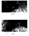
- a first shading style is to apply shading that depends on the absolute elevation of an individual point in the image.
- a typical shading pattern produced using predominantly this style is illustrated in Fig. 5f .
- Darker image shading represents points of higher elevation. For example, peaks 30 are indicated by areas of local maxima in darkness shading, whereas valleys 32 are indicated by areas of local minima in darkness (local maxima in lightness).
- This first type of shading style is suitable for relatively small display scales (high zoom out away from the map), in which there may be significant changes in absolute elevation in close proximity in the map image.
- the first shading style is less suitable for relatively large display scales (zoomed in towards the map), in which the elevation may be substantially the same across the entire display image, leading to almost constant shading that obscures local relief features.
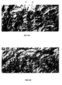
- a very different second shading style is based on elevation slope, namely the difference in elevation between adjacent points in the display image, taken in a certain sampling direction, for example, from North-West to South-East.
- a negative slope is rendered with one type of shading (e.g. with a lighter colour 34), and a positive slope with another type of shading (e.g. a darker colour 36). The steeper the slope the lighter or respective darker the colour that is used.
- a typical shading pattern produced using predominantly this style is illustrated in Fig. 5a .
- This second shading style is suited to large display scales (zoomed in towards the map), it is more responsive to local relief detail even though the absolute elevation may change only fractionally, and can generate intuitive shading for large display scale.
- the second shading style technique is less well suited to small display scale, where two display points on which the slope is calculated may be geographically remote, and so calculating an elevation slope between these points may not provide useful information. For example, if the two display points are of about the same elevation, but on opposite sides of a mountain peak, then the peak will not be represented by any shading using the second technique, because there is little difference between the elevations at the two display points, and important elevation features can easily be lost.
- the shading algorithm preferably combines first and second different shading functions or styles, each weighted by a respective coefficient indicating the respective strength of contribution of each shading function as a component of the shading algorithm.
- the coefficients vary as a function of the display scale information 28 (for example, the zoom out height "z"). More preferably, the coefficients vary as a substantially continuous function of the display scale information.
- a single coefficient l ( z ) may be used, where l ( z ) takes values between zero and 1, ( l ( z ) ⁇ [0,1]), with l ( z ) representing the weight of one shading function, and 1- l ( z ) representing the weight of the other shading function.
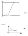
- the coefficient l ( z ) could vary linearly as a function of the display scale "z". However, referring to Fig. 3 , it is preferred that l ( z ) vary asymptotically between two limits as a function of the display scale. At large and medium display scales (small and medium “zoom-out” levels “z" away from the map), the predominant shading function is the slope based shading function (second shading function) and at small display scales (high “zoom-out” level "z"), the predominant shading function is the absolute elevation based function (first shading function). The value of l is big in the first case and small in the second.
- the function l (z) is preferably chosen to be composed by a sequence of two Bezier spline curve.
- the main idea behind this approach is to use a function which is "almost" asymptotic towards 0 when z approaches A and "almost” asymptotic towards 1 when z approaches E.
- the zoom value z in A as the lowest zoom level considered in this case and the value in E as the highest.
- Choosing a sequence of two Bezier splines can achieve the freedom to choose different convergence rates for the evolution up to the break even point C and for the one afterwards. It is essentially this type of evolution and the solution chosen which gives to the solution an optimal transition between the two criteria.
- the control points A, B, C, D, E can be tuned to achieve the optimal transition between the two shading criteria.
- the main formula also includes two sub-unitary, or secondary, weight functions for "tuning" the combined shading effect.
- the W 1 (sin( ⁇ )) component is a sub-unitary weight function which tries to attenuate the height values of the slope and has a descending hyperbolic graphic, which "almost” asymptotically approach a minimum value when sin( ⁇ ) approaches 1 (as illustrated in Fig. 4 ).
- W 2 (h) has the same type of evolution but this time as h approaches the conventional maximal value of the altitude.
- Fig. 5 illustrates a range of screenshots for different zoom out levels to illustrate the way the method works.
- the screenshots show how the shading algorithm works for a region in the Alps (around Alagna Valssesia in Italy) starting from the medium zoom levels to the higher ones.
- the elevation information 20a is provided as absolute elevation information for points in the digital map 20, and the rending module 22 performs all of the calculations necessary to calculate a shading percentage to apply to each display pixel.
- the elevation information 20a could, alternatively or additionally, include pre-calculated values (for example of one or more of h, ⁇ , P height ( h ), P slope ( ⁇ ) , and/or l ( z )), for use in the shading algorithm, to reduce the calculation burden within the rendering module.
- the elevation information 20a may be represented directly as the pre-calculated shading percentages according to the first and second different shading functions.
- the shading percentages may be pre-calculated in the digital map 20
- the provision of at least first and second different shading percentages for the same point can enable dynamic rending according to the display scale, by applying a weighted combination of the two pre-calculated percentages using the same principles as described above.
- Fig. 2 such additional elevation information is represented in the digital map 20 at 20b.
- the shading algorithm has been expressed as a mathematical function that may be calculated on demand by a suitable processor
- a function map containing pre-calculated values, for example, as a function of look-up coordinate variables ( ⁇ the angle of the elevation slope, h the current height (elevation), and z the zoom-out level (display scale)).
- ⁇ the angle of the elevation slope
- h the current height
- z the zoom-out level
- Such a pre-calculated function map could be provided within the map display apparatus, or it could be incorporated as an integral part of the data representing the digital map 20 (represented in Fig. 2 at 20c).
- Figs. 6, 7 and 8 represent different types of apparatus that may implement the techniques of the preferred embodiment.
- Fig. 6 illustrates a handheld PND 50
- Fig. 7 illustrates a PND 52 suitable for in-vehicle use.
- the PNDs 50 and 52 typically store the digital map 20 by using semiconductor and/or magnetic memory media.
- the PNDs 50 and 52 typically include a local processor, that implements the rendering module 22 by execution of software.
- Fig. 8 illustrates a networked computer system 60 comprising a server 62 communicating with one or more terminals 64 via a network 66.
- the network 66 may include a local intranet and/or a wider internet (such as the world-wide-web).
- the server 62 stores the digital map 20 and supplies map image generation information upon demand to a requesting terminal 64.
- the server 62 may perform the image calculation, including the function of the map rendering module 22, in order to provide an already-rendered image to the terminal 64 for display.
- the terminal 64 may perform the image calculation, including the function of the map rendering module 22, based on unrendered information received from the server 62.
- the function of the map rendering module 22 may be divided amongst both the server 62 and the terminal 64, to include both server processing and local terminal processing.
Abstract
Description
- This invention relates to an apparatus and method for generating a display from a digital map, the display including a representation of elevation information. The invention is especially suitable for navigation devices, including portable navigation devices (so-called PNDs), but may find utility in any type of processing device for generating a display from digital map information.
- Two methods are known for rendering elevation information in a display generated from an electronic map, namely (i) isolines (also called contour lines) representing points of the same elevation, and (ii) shading of the map colour to represent elevation information. While isolines may provide an accurate representation of elevation, isolines can clutter the map display and are not intuitive to all users. Map clutter may be a particular problem when displaying the map on a relatively small electronic display device, or when it is also desired to display other map information such as navigation and location information. Shading can provide a more intuitive representation of elevation information without cluttering the display. As used herein, the term "shading" means applying a darkening and/or lightening of the map colour, akin to a positive or negative shadow.
- Referring to
Fig. 1 , a conventional technique for shading is to include the shading as a static feature of the map colour in the digital map. Adigital map 12 is generated by processingmap source information 10 that includes elevation data, to create the shading as a static template within the background colour in thedigital map 12. To display thedigital map 12, arendering process 14 is used to generate animage 18 including the fixed elevation shading template at a desired display scale represented by adisplay scale input 16. - In devising the present invention, it has been appreciated that the above technique lacks considerable finesse in being able to adapt to displaying the map at different viewing scales or zoom levels. The shading is fixed as part of the
digital map 12, and is not adaptive. The shading pattern also depends on the specific shading technique used when creating thedigital map 12. Different shading techniques create different shading patterns based on the same elevation data. While a certain shading technique may be suited to displaying the map at a certain display scale, generating a display at other display scales can require interpolation or averaging of the shading pattern. This can create severe inaccuracies in the elevation shading. For example, as the display scale is varied, peaks and valleys in the elevation may appear to change shape and location as a result of averaging or interpolation inaccuracies. - Document
EP1498864, published on 19.01.2005 , discloses a method to display a digital map using different shading values for different elevation values of the points of the map, i.e. the shading values vary as a function of the elevation information. - The present invention has been devised bearing the above problems in mind.
- In pursuit of this aim, a presently preferred embodiment of the present invention provides a method of rendering a display image generated from digital map information. The method includes the steps of:
- determining elevation information from the digital map information;
- determining display scale information for the display image; and
- determining a shading value to apply to a pixel in the display image, and
- applying the shading value to the respective pixel in the display image, to generate a display that represents elevation information by pixel shading.
- The shading value varies as a function of the elevation information and the display scale information, whereby the display is generated to represent elevation information by pixel shading that varies with display scale.
- Features and advantages of the invention include: (i) ability to dynamically render a map image with elevation shading that is relevant to the display scale being used; (ii) ability to smoothly vary the elevation shading as the display scale is varied between two extremes; and (iii) avoiding the problems of a single fixed shading pattern used in the prior art.
- Various aspects of the teachings of the present invention, and arrangements embodying those teachings, will hereafter be described by way of illustrative example with reference to the accompanying drawings, in which:
-
Fig. 1 is a schematic illustration of a conventional application of shading during the creation of a digital map; -
Fig. 2 is a schematic illustration of processing in a preferred embodiment of the invention, using dynamic processing to render a map display using display scale information; -
Fig. 3 is a schematic illustration of a weighting function used in a shading algorithm of the preferred embodiment; -
Fig. 4 is a schematic illustration of a sub-weighting function used in the shading algorithm of the preferred embodiment; -
Figs. 5a - 5f are schematic illustrations of screenshots of a rendered map image at different display scales, decreasing in display scale (increasing in zoom out height) fromFig. 5a to Fig. 5f ; -
Fig. 6 is a schematic perspective view of a PND; -
Fig. 7 is a schematic perspective view of a PND for in-vehicle use; and -
Fig. 8 is a schematic block diagram of a network based map display system. - Preferred embodiments of the present invention are now described with reference to any system for generating a display using a digital map. The system may comprise an automomous device, such as a portable navigation device, a portable map viewer, a device including a positioning system (for example, a satellite based positioning system such as a Global Positioning System (GPS)), a portable digital assistant (PDA), a portable computer, or non-portable computer. Alternatively, the system may comprise a server storing the digital map, and a remote terminal or computer configured to generate a display of the digital map based on information received from the server over one or more networks, such as an internet or intranet. One application for which provision of elevation information is especially useful is for a pedestrian and hiking navigation device or system.
-
Fig. 2 illustrates schematically a technique for generating a map display including elevation shading in a preferred embodiment. Adigital map 20 includeselevation information 20a indicative of elevation at different points in thedigital map 20. Thedigital map 20 may be a database of map information stored in any suitable storage medium, for example but not limited to, an optical storage medium, non-volatile electronic memory, volatile electronic memory, a magnetic storage medium, or a magneto-optical storage medium. Theelevation information 20a may represent a grid of values (a matrix of points). It makes no difference the way the data is stored. As an example, the surface of the Earth may be divided in some small patches of 3" in latitude and 3" in longitude. This mean that the distance between two adjacent points in the data matrix on vertical will be of 3" (about 90m considering that the length of a degree of latitude is almost the same regardless of the position). On horizontal it will be also 3" (the values in meters will depend on the latitude in this case). - A
map rendering module 22 dynamically renders adisplay image 24 based on (i)map information 26 received from thedigital map 20, (ii)elevation information 26a also received from thedigital map 20, and (iii)display scale information 28 indicating the display scale of theimage 24, ie. the degree to which the map image is zoomed in towards, or zoomed out from, the map. In one form, the display scale is represented by a notional viewing (or zoom-out) height value "z" above the map. A relatively large display scale is represented by a respectively small value of z, and a relatively small display scale is respresented by a respectively large value of z. Themap rendering module 22 may comprise dedicated graphics processor circuitry and/or rendering software executed by a general purpose processor. - The
map rendering module 22 is configured to render the map by applying a shading algorithm that darkens and/or lightens the map color to represent elevation in themap image 24. The output will be represented by the percentage of shading applied to each pixel on the screen. The screen is normally represented by a matrix of pixels, which gives the resolution of the screen. Each pixel has a colour associated with, in this case, the form of relief that it represents (for example, different colours for meadow, forest, built area, etc.), as represented by themap information 26. The term "shading percentage" is an indication of the extent that the colour should be darkened or made lighter (whitened). A negative shading percentage takes the colour closer to white, and a positive shading percentage takes the colour closer to black. The shading algorithm is a function of (i) theelevation information 20a/26a from thedigital map 20, and (ii) thedisplay scale information 28. The shading algorithm is configured to vary the shading style based on the same elevation information, as a varying function of the display scale information. In other words, as the display scale is varied, not just the magnification of the shading is varied, but also the style of shading. This enables the style of shading to be adapted to the display scale of theimage 24. - Before the overall shading algorithm is explained, it is useful to illustrate how two different styles of shading produce different shading patterns suitable for different display scales.
- A first shading style is to apply shading that depends on the absolute elevation of an individual point in the image. A typical shading pattern produced using predominantly this style is illustrated in
Fig. 5f . Darker image shading represents points of higher elevation. For example, peaks 30 are indicated by areas of local maxima in darkness shading, whereasvalleys 32 are indicated by areas of local minima in darkness (local maxima in lightness). This first type of shading style is suitable for relatively small display scales (high zoom out away from the map), in which there may be significant changes in absolute elevation in close proximity in the map image. The first shading style is less suitable for relatively large display scales (zoomed in towards the map), in which the elevation may be substantially the same across the entire display image, leading to almost constant shading that obscures local relief features. - A very different second shading style is based on elevation slope, namely the difference in elevation between adjacent points in the display image, taken in a certain sampling direction, for example, from North-West to South-East. A negative slope is rendered with one type of shading (e.g. with a lighter colour 34), and a positive slope with another type of shading (e.g. a darker colour 36). The steeper the slope the lighter or respective darker the colour that is used. A typical shading pattern produced using predominantly this style is illustrated in
Fig. 5a . This second shading style is suited to large display scales (zoomed in towards the map), it is more responsive to local relief detail even though the absolute elevation may change only fractionally, and can generate intuitive shading for large display scale. However, the second shading style technique is less well suited to small display scale, where two display points on which the slope is calculated may be geographically remote, and so calculating an elevation slope between these points may not provide useful information. For example, if the two display points are of about the same elevation, but on opposite sides of a mountain peak, then the peak will not be represented by any shading using the second technique, because there is little difference between the elevations at the two display points, and important elevation features can easily be lost. - In the present embodiment, the shading algorithm preferably combines first and second different shading functions or styles, each weighted by a respective coefficient indicating the respective strength of contribution of each shading function as a component of the shading algorithm. Preferably, the coefficients vary as a function of the display scale information 28 (for example, the zoom out height "z"). More preferably, the coefficients vary as a substantially continuous function of the display scale information. When two shading functions are used, a single coefficient l(z) may be used, where l(z) takes values between zero and 1, (l(z) ∈ [0,1]), with l(z) representing the weight of one shading function, and 1-l(z) representing the weight of the other shading function.
- The coefficient l(z) could vary linearly as a function of the display scale "z". However, referring to
Fig. 3 , it is preferred that l(z) vary asymptotically between two limits as a function of the display scale. At large and medium display scales (small and medium "zoom-out" levels "z" away from the map), the predominant shading function is the slope based shading function (second shading function) and at small display scales (high "zoom-out" level "z"), the predominant shading function is the absolute elevation based function (first shading function). The value of l is big in the first case and small in the second. - In a preferred embodiment, and using the following variables:
- α the angle of the elevation slope,
- h the current height (elevation) and
- z the zoom-out level (display scale)
- As illustrated in
Fig. 3 , the function l(z) is preferably chosen to be composed by a sequence of two Bezier spline curve. The main idea behind this approach is to use a function which is "almost" asymptotic towards 0 when z approaches A and "almost" asymptotic towards 1 when z approaches E. We may see in this case the zoom value z in A as the lowest zoom level considered in this case and the value in E as the highest. Choosing a sequence of two Bezier splines (see ABC and CDE) can achieve the freedom to choose different convergence rates for the evolution up to the break even point C and for the one afterwards. It is essentially this type of evolution and the solution chosen which gives to the solution an optimal transition between the two criteria. The control points A, B, C, D, E can be tuned to achieve the optimal transition between the two shading criteria. - The two shading percentage functions presented above can be computed by using the following formulas:


- The main formula also includes two sub-unitary, or secondary, weight functions for "tuning" the combined shading effect. The W 1(sin(α)) component is a sub-unitary weight function which tries to attenuate the height values of the slope and has a descending hyperbolic graphic, which "almost" asymptotically approach a minimum value when sin(α) approaches 1 (as illustrated in
Fig. 4 ). W2(h)has the same type of evolution but this time as h approaches the conventional maximal value of the altitude. As a remark, W2(h)is dependent also on the altitude h but the main difference with respect of Pheight (h) is that in this case the height is only used to accentuate the globally computed percentage P with respect of the altitude to give a bulk view over the mountains missives but it doesn't change the nature of the rendering (the sign of the shading percentage doesn't change). At the same altitude two pixels with the same slope will have the same shading percentage. The only difference is that the same slope will be more visible at higher altitude than in the plains. These secondary weight functions provide useful tuning of the graphic effect in the display, but could be omitted if preferred. -
Fig. 5 illustrates a range of screenshots for different zoom out levels to illustrate the way the method works. The screenshots show how the shading algorithm works for a region in the Alps (around Alagna Valssesia in Italy) starting from the medium zoom levels to the higher ones. The zoom out levels are:Fig. 5a , z = 372 (weighting coefficient l(z)=0);Fig. 5b , z= 561 (weighting coefficient l(z) = 0.091);Fig. 5c , z = 846 (weighting coefficient l(z) = 0.201);Fig. 5d , z = 1134 (weighting coefficient l(z) = 0.355);Fig. 5e , z = 1520 (weighting coefficient l(z) = 0.595); andFig. 5f , z = 3073 (weighting coefficient l(z) = 0.743). The shading based on slope is done from North-West to South-East. InFig. 5 , it can be seen how, as the zoom-out level "z" increases (moving from large display scale to small display scale) the display smoothly shifts from one type of shading style rendering to another. The negative lighter slopes become darker but the overall image continues to give a correct image of the relief. In correlation withFig. 3 the following values for the zoom level thresholds may be used: - A point (start transition) - z = 500,
- C point (break even point) - z =1500,
- E point (end of transition) - z = 4500.
- In the present embodiment, the
elevation information 20a is provided as absolute elevation information for points in thedigital map 20, and the rendingmodule 22 performs all of the calculations necessary to calculate a shading percentage to apply to each display pixel. In an alternative form, theelevation information 20a could, alternatively or additionally, include pre-calculated values (for example of one or more of h, α, Pheight (h), Pslope (α), and/or l(z)), for use in the shading algorithm, to reduce the calculation burden within the rendering module. In one alternative, theelevation information 20a may be represented directly as the pre-calculated shading percentages according to the first and second different shading functions. Even though the shading percentages may be pre-calculated in thedigital map 20, the provision of at least first and second different shading percentages for the same point, can enable dynamic rending according to the display scale, by applying a weighted combination of the two pre-calculated percentages using the same principles as described above. InFig. 2 , such additional elevation information is represented in thedigital map 20 at 20b. - Although the shading algorithm has been expressed as a mathematical function that may be calculated on demand by a suitable processor, an alternative is to provide a function map containing pre-calculated values, for example, as a function of look-up coordinate variables (α the angle of the elevation slope, h the current height (elevation), and z the zoom-out level (display scale)). Such a pre-calculated function map could be provided within the map display apparatus, or it could be incorporated as an integral part of the data representing the digital map 20 (represented in
Fig. 2 at 20c). -
Figs. 6, 7 and 8 represent different types of apparatus that may implement the techniques of the preferred embodiment.Fig. 6 , illustrates ahandheld PND 50, andFig. 7 illustrates aPND 52 suitable for in-vehicle use. ThePNDs digital map 20 by using semiconductor and/or magnetic memory media. ThePNDs rendering module 22 by execution of software.Fig. 8 illustrates anetworked computer system 60 comprising aserver 62 communicating with one or more terminals 64 via anetwork 66. Thenetwork 66 may include a local intranet and/or a wider internet (such as the world-wide-web). Theserver 62 stores thedigital map 20 and supplies map image generation information upon demand to a requesting terminal 64. In one form, theserver 62 may perform the image calculation, including the function of themap rendering module 22, in order to provide an already-rendered image to the terminal 64 for display. In another form, the terminal 64 may perform the image calculation, including the function of themap rendering module 22, based on unrendered information received from theserver 62. Alternatively, the function of themap rendering module 22 may be divided amongst both theserver 62 and the terminal 64, to include both server processing and local terminal processing. - It will be appreciated that whilst various aspects and embodiments of the present invention have heretofore been described, the scope of the present invention is not limited to the particular arrangements set out herein and instead extends to encompass all arrangements, and modifications and alterations thereto, which fall within the scope of the appended claims.


Claims (14)
- A method of rendering a display image generated from digital map information, the method comprising: determining elevation information (20a) from the digital map information (20); determining display scale information (28) for the display image; and determining (22) a shading value to apply to a pixel in the display image, applying the shading value to the respective pixel in the display image, to generate a display (24) that represents elevation information by pixel shading; characterised in that the shading value varies as a function of the elevation information and the display scale information, whereby the display is generated to represent elevation information by pixel shading that varies with display scale.
- The method of claim 1 , wherein the step of determining (22) a shading value comprises combining first and second shading functions according to at least one weight coefficient that determines the relative contribution of each shading function.
- The method of claim 2, wherein the at least one weight coefficient varies dependently on the display scale information.
- The method of claim 2 or 3, wherein the first shading function is a function that generates a shading style suitable for a small display scale image.
- The method of claim 2, 3 or 4, wherein the first shading function is a function that varies dependently on absolute elevation.
- The method of any of claims 2 to 5, wherein the second shading function is a function that generates a shading style suitable for a large display scale.
- The method of any of claims 2 to 6, wherein the second shading function is a function that varies dependently on elevation slope.
- The method of any of claims 2 to 7, wherein the step of determining a shading value comprises using a shading algorithm represented by:

wherein:p is the shading value to apply to a pixel;z is a parameter depending on display scale;I(z) is a weight coefficient that varies in the interval [0, 1] with the display scale;α is the elevation slope;h is the absolute elevation;Pslope is a shading function that varies with elevation slope;Pheight is a shading function that varies with absolute elevation;W1 and W2 are constants. - The method of any of claims 2 to 8, wherein the at least one weight coefficient varies asymptotically between the values of 0 and 1, one of said values corresponding to a relatively large display scale, and the other of said values corresponding to a relatively small display scale.
- The method of any of claims 2 to 9, wherein the at least one weight coefficient varies as a continuous function of the display scale information.
- The method of any of claims 2 to 10, wherein the at least one weight coefficient varies as a function represented by a sequence of first and second Bezier spline curves.
- The method of any preceding claim wherein the elevation information comprises at least one item of information selected from: absolute elevation; elevation slope; first shading information representing a first elevation shading function; second shading information representing a second elevation shading function.
- A computer program which, when executed by a processor, configures the processor to perform any of the methods of claims 1-12.
- Apparatus for rendering a display image generated from digital map information, the apparatus being configured to perform the methods of any of claims 1-12.
Applications Claiming Priority (2)
| Application Number | Priority Date | Filing Date | Title |
|---|---|---|---|
| US87960707P | 2007-01-10 | 2007-01-10 | |
| PCT/EP2008/000182 WO2008083979A1 (en) | 2007-01-10 | 2008-01-09 | Displaying elevation information from a digital map |
Publications (2)
| Publication Number | Publication Date |
|---|---|
| EP2104926A1 EP2104926A1 (en) | 2009-09-30 |
| EP2104926B1 true EP2104926B1 (en) | 2012-07-25 |
Family
ID=39319614
Family Applications (1)
| Application Number | Title | Priority Date | Filing Date |
|---|---|---|---|
| EP08701086A Active EP2104926B1 (en) | 2007-01-10 | 2008-01-09 | Displaying elevation information from a digital map |
Country Status (9)
| Country | Link |
|---|---|
| US (1) | US8553946B2 (en) |
| EP (1) | EP2104926B1 (en) |
| JP (1) | JP2010515941A (en) |
| CN (1) | CN101578636A (en) |
| AR (1) | AR064840A1 (en) |
| AU (1) | AU2008204558A1 (en) |
| RU (1) | RU2009130385A (en) |
| TW (1) | TW200839188A (en) |
| WO (1) | WO2008083979A1 (en) |
Families Citing this family (10)
| Publication number | Priority date | Publication date | Assignee | Title |
|---|---|---|---|---|
| US8553946B2 (en) * | 2007-01-10 | 2013-10-08 | Tomtom International B.V. | Displaying elevation information from a digital map |
| EP2336724A3 (en) * | 2009-12-18 | 2012-01-11 | Navigon AG | Method for operating a navigation system |
| KR20130080163A (en) | 2012-01-04 | 2013-07-12 | 삼성전자주식회사 | Method for displaying digital map in client and apparatus thereof |
| TW201405098A (en) * | 2012-07-18 | 2014-02-01 | Tian-Min Gao | Map and method for searching on map |
| US9483846B2 (en) * | 2013-05-29 | 2016-11-01 | Microsoft Technology Licensing, Llc | Data interpolation and classification method for map data visualization |
| GB201405540D0 (en) * | 2014-03-27 | 2014-05-14 | Tomtom Int Bv | Map Generation |
| AU2014202959B2 (en) | 2014-05-30 | 2020-10-15 | Caterpillar Of Australia Pty Ltd | Illustrating elevations associated with a mine worksite |
| US10055885B2 (en) * | 2015-09-16 | 2018-08-21 | Raytheon Company | Systems and methods for digital elevation map filters for three dimensional point clouds |
| CN109472864B (en) * | 2017-09-07 | 2022-12-27 | 广州极飞科技股份有限公司 | Generation method and device of elevation tile map |
| CN109166307B (en) * | 2018-06-15 | 2021-11-05 | 中国地质大学(武汉) | Visual metaphor expression method and system for time-space accessibility of traffic network |
Family Cites Families (19)
| Publication number | Priority date | Publication date | Assignee | Title |
|---|---|---|---|---|
| GB2091526B (en) * | 1981-01-13 | 1985-10-02 | Harris Corp | Digital map generator and display system |
| US5542032A (en) * | 1993-10-04 | 1996-07-30 | Loral Federal Systems Company | Fast display of images of three-dimensional surfaces without aliasing |
| DE69408473T2 (en) * | 1993-10-15 | 1998-08-27 | Evans & Sutherland Computer Co | DIRECT RENDERING OF TEXTURED HEIGHT FIELDS |
| GB9717656D0 (en) * | 1997-08-20 | 1997-10-22 | Videologic Ltd | Shading three dimensional images |
| US6288721B1 (en) * | 1999-07-07 | 2001-09-11 | Litton Systems, Inc. | Rendering process and method for digital map illumination intensity shading |
| DE19963764A1 (en) * | 1999-12-30 | 2001-07-05 | Bosch Gmbh Robert | Method, control panel, navigation system and interface for displaying sections of a digital map base |
| CA2423114C (en) * | 2000-08-25 | 2009-11-17 | Limbic Systems, Inc. | Method for conducting analysis of two-dimensional images |
| US6600489B2 (en) * | 2000-12-14 | 2003-07-29 | Harris Corporation | System and method of processing digital terrain information |
| US6765584B1 (en) * | 2002-03-14 | 2004-07-20 | Nvidia Corporation | System and method for creating a vector map in a hardware graphics pipeline |
| JP4429737B2 (en) * | 2002-04-22 | 2010-03-10 | 株式会社デージーエス・コンピュータ | Method and apparatus for creating digital topographic map |
| TWI285852B (en) * | 2002-11-05 | 2007-08-21 | Asia Air Survey Co Ltd | System and method for visualization processing and recording medium with visualization processing program recorded therein |
| US7098809B2 (en) * | 2003-02-18 | 2006-08-29 | Honeywell International, Inc. | Display methodology for encoding simultaneous absolute and relative altitude terrain data |
| US7116806B2 (en) * | 2003-10-23 | 2006-10-03 | Lumeniq, Inc. | Systems and methods relating to AFIS recognition, extraction, and 3-D analysis strategies |
| US7107146B2 (en) * | 2003-12-10 | 2006-09-12 | Honeywell International Inc. | Methods and systems for generating a terrain elevation map in a cartesian format |
| US7242407B2 (en) * | 2004-05-28 | 2007-07-10 | Lockheed Martin Corporation | Reprojecting map images using graphical techniques |
| US7283654B2 (en) * | 2004-08-26 | 2007-10-16 | Lumeniq, Inc. | Dynamic contrast visualization (DCV) |
| US7612775B2 (en) * | 2005-07-28 | 2009-11-03 | The Boeing Company | Real-time conformal terrain rendering |
| US20070146364A1 (en) * | 2005-12-22 | 2007-06-28 | Aspen Sven D | Methods and systems for displaying shaded terrain maps |
| US8553946B2 (en) * | 2007-01-10 | 2013-10-08 | Tomtom International B.V. | Displaying elevation information from a digital map |
-
2008
- 2008-01-09 US US12/007,375 patent/US8553946B2/en active Active
- 2008-01-09 WO PCT/EP2008/000182 patent/WO2008083979A1/en active Application Filing
- 2008-01-09 JP JP2009545145A patent/JP2010515941A/en not_active Withdrawn
- 2008-01-09 EP EP08701086A patent/EP2104926B1/en active Active
- 2008-01-09 AU AU2008204558A patent/AU2008204558A1/en not_active Abandoned
- 2008-01-09 RU RU2009130385/08A patent/RU2009130385A/en not_active Application Discontinuation
- 2008-01-09 CN CNA2008800018050A patent/CN101578636A/en active Pending
- 2008-01-10 AR ARP080100098A patent/AR064840A1/en unknown
- 2008-01-10 TW TW097101034A patent/TW200839188A/en unknown
Also Published As
| Publication number | Publication date |
|---|---|
| JP2010515941A (en) | 2010-05-13 |
| EP2104926A1 (en) | 2009-09-30 |
| CN101578636A (en) | 2009-11-11 |
| US8553946B2 (en) | 2013-10-08 |
| RU2009130385A (en) | 2011-02-20 |
| US20080212893A1 (en) | 2008-09-04 |
| TW200839188A (en) | 2008-10-01 |
| AR064840A1 (en) | 2009-04-29 |
| AU2008204558A1 (en) | 2008-07-17 |
| WO2008083979A1 (en) | 2008-07-17 |
Similar Documents
| Publication | Publication Date | Title |
|---|---|---|
| EP2104926B1 (en) | Displaying elevation information from a digital map | |
| AU2014227060B2 (en) | Image processing device, method for image processing, and image processing program | |
| US8274524B1 (en) | Map rendering using interpolation of style parameters across zoom levels | |
| US6339747B1 (en) | Weather tracking and display system and method | |
| USRE40466E1 (en) | Method for organizing and compressing spatial data | |
| US20060206264A1 (en) | Combined map scale and measuring tool | |
| US8731305B1 (en) | Updating map data using satellite imagery | |
| WO2009027788A2 (en) | Chart display device and method for displaying chart | |
| CN105022731B (en) | A kind of method of map vector tile caching | |
| WO2007078709A2 (en) | Methods and systems for displaying shaded terrain maps | |
| CN109086286B (en) | Method for producing and publishing color topographic map | |
| US20060285764A1 (en) | Model-based line width control | |
| US8224098B2 (en) | Façade rendering system | |
| Gil et al. | DEM shading method for the correction of pseudoscopic effect on multi-platform satellite imagery | |
| US20050146524A1 (en) | System and method for determining a spatial hierarchy for polygonal data by using cube-root scaling | |
| US20160078651A1 (en) | Proximity-Base Detail Reduction of Geographic Data | |
| CN104346771B (en) | A kind of electronic map tiered management approach | |
| Clemson et al. | Observational constraints on thawing quintessence models | |
| US10546418B2 (en) | Visualization of positional geospatial uncertainty | |
| US9275481B2 (en) | Viewport-based contrast adjustment for map features | |
| CN116188587A (en) | Positioning method and device and vehicle | |
| JP6995912B2 (en) | Topographic map output device, topographic map output method and program | |
| CN111429542A (en) | Vector contour line speckle pattern generation method and device and storage medium | |
| US7598955B1 (en) | Hinted stem placement on high-resolution pixel grid | |
| US11056079B2 (en) | Display system and program |
Legal Events
| Date | Code | Title | Description |
|---|---|---|---|
| PUAI | Public reference made under article 153(3) epc to a published international application that has entered the european phase |
Free format text: ORIGINAL CODE: 0009012 |
|
| 17P | Request for examination filed |
Effective date: 20090610 |
|
| AK | Designated contracting states |
Kind code of ref document: A1 Designated state(s): AT BE BG CH CY CZ DE DK EE ES FI FR GB GR HR HU IE IS IT LI LT LU LV MC MT NL NO PL PT RO SE SI SK TR |
|
| DAX | Request for extension of the european patent (deleted) | ||
| RAP1 | Party data changed (applicant data changed or rights of an application transferred) |
Owner name: TOMTOM INTERNATIONAL B.V. |
|
| REG | Reference to a national code |
Ref country code: DE Ref legal event code: R079 Ref document number: 602008017391 Country of ref document: DE Free format text: PREVIOUS MAIN CLASS: G06T0017500000 Ipc: G06T0017050000 |
|
| RIC1 | Information provided on ipc code assigned before grant |
Ipc: G06T 17/05 20110101AFI20120213BHEP |
|
| GRAP | Despatch of communication of intention to grant a patent |
Free format text: ORIGINAL CODE: EPIDOSNIGR1 |
|
| GRAS | Grant fee paid |
Free format text: ORIGINAL CODE: EPIDOSNIGR3 |
|
| GRAA | (expected) grant |
Free format text: ORIGINAL CODE: 0009210 |
|
| AK | Designated contracting states |
Kind code of ref document: B1 Designated state(s): AT BE BG CH CY CZ DE DK EE ES FI FR GB GR HR HU IE IS IT LI LT LU LV MC MT NL NO PL PT RO SE SI SK TR |
|
| REG | Reference to a national code |
Ref country code: GB Ref legal event code: FG4D |
|
| REG | Reference to a national code |
Ref country code: CH Ref legal event code: EP |
|
| REG | Reference to a national code |
Ref country code: AT Ref legal event code: REF Ref document number: 567968 Country of ref document: AT Kind code of ref document: T Effective date: 20120815 Ref country code: IE Ref legal event code: FG4D |
|
| REG | Reference to a national code |
Ref country code: NL Ref legal event code: T3 |
|
| REG | Reference to a national code |
Ref country code: DE Ref legal event code: R096 Ref document number: 602008017391 Country of ref document: DE Effective date: 20120920 |
|
| REG | Reference to a national code |
Ref country code: AT Ref legal event code: MK05 Ref document number: 567968 Country of ref document: AT Kind code of ref document: T Effective date: 20120725 |
|
| REG | Reference to a national code |
Ref country code: LT Ref legal event code: MG4D Effective date: 20120725 |
|
| PG25 | Lapsed in a contracting state [announced via postgrant information from national office to epo] |
Ref country code: FI Free format text: LAPSE BECAUSE OF FAILURE TO SUBMIT A TRANSLATION OF THE DESCRIPTION OR TO PAY THE FEE WITHIN THE PRESCRIBED TIME-LIMIT Effective date: 20120725 Ref country code: IS Free format text: LAPSE BECAUSE OF FAILURE TO SUBMIT A TRANSLATION OF THE DESCRIPTION OR TO PAY THE FEE WITHIN THE PRESCRIBED TIME-LIMIT Effective date: 20121125 Ref country code: NO Free format text: LAPSE BECAUSE OF FAILURE TO SUBMIT A TRANSLATION OF THE DESCRIPTION OR TO PAY THE FEE WITHIN THE PRESCRIBED TIME-LIMIT Effective date: 20121025 Ref country code: AT Free format text: LAPSE BECAUSE OF FAILURE TO SUBMIT A TRANSLATION OF THE DESCRIPTION OR TO PAY THE FEE WITHIN THE PRESCRIBED TIME-LIMIT Effective date: 20120725 Ref country code: HR Free format text: LAPSE BECAUSE OF FAILURE TO SUBMIT A TRANSLATION OF THE DESCRIPTION OR TO PAY THE FEE WITHIN THE PRESCRIBED TIME-LIMIT Effective date: 20120725 Ref country code: BE Free format text: LAPSE BECAUSE OF FAILURE TO SUBMIT A TRANSLATION OF THE DESCRIPTION OR TO PAY THE FEE WITHIN THE PRESCRIBED TIME-LIMIT Effective date: 20120725 Ref country code: CY Free format text: LAPSE BECAUSE OF FAILURE TO SUBMIT A TRANSLATION OF THE DESCRIPTION OR TO PAY THE FEE WITHIN THE PRESCRIBED TIME-LIMIT Effective date: 20120725 Ref country code: LT Free format text: LAPSE BECAUSE OF FAILURE TO SUBMIT A TRANSLATION OF THE DESCRIPTION OR TO PAY THE FEE WITHIN THE PRESCRIBED TIME-LIMIT Effective date: 20120725 |
|
| PG25 | Lapsed in a contracting state [announced via postgrant information from national office to epo] |
Ref country code: GR Free format text: LAPSE BECAUSE OF FAILURE TO SUBMIT A TRANSLATION OF THE DESCRIPTION OR TO PAY THE FEE WITHIN THE PRESCRIBED TIME-LIMIT Effective date: 20121026 Ref country code: PL Free format text: LAPSE BECAUSE OF FAILURE TO SUBMIT A TRANSLATION OF THE DESCRIPTION OR TO PAY THE FEE WITHIN THE PRESCRIBED TIME-LIMIT Effective date: 20120725 Ref country code: LV Free format text: LAPSE BECAUSE OF FAILURE TO SUBMIT A TRANSLATION OF THE DESCRIPTION OR TO PAY THE FEE WITHIN THE PRESCRIBED TIME-LIMIT Effective date: 20120725 Ref country code: PT Free format text: LAPSE BECAUSE OF FAILURE TO SUBMIT A TRANSLATION OF THE DESCRIPTION OR TO PAY THE FEE WITHIN THE PRESCRIBED TIME-LIMIT Effective date: 20121126 Ref country code: SI Free format text: LAPSE BECAUSE OF FAILURE TO SUBMIT A TRANSLATION OF THE DESCRIPTION OR TO PAY THE FEE WITHIN THE PRESCRIBED TIME-LIMIT Effective date: 20120725 Ref country code: SE Free format text: LAPSE BECAUSE OF FAILURE TO SUBMIT A TRANSLATION OF THE DESCRIPTION OR TO PAY THE FEE WITHIN THE PRESCRIBED TIME-LIMIT Effective date: 20120725 |
|
| PG25 | Lapsed in a contracting state [announced via postgrant information from national office to epo] |
Ref country code: DK Free format text: LAPSE BECAUSE OF FAILURE TO SUBMIT A TRANSLATION OF THE DESCRIPTION OR TO PAY THE FEE WITHIN THE PRESCRIBED TIME-LIMIT Effective date: 20120725 Ref country code: EE Free format text: LAPSE BECAUSE OF FAILURE TO SUBMIT A TRANSLATION OF THE DESCRIPTION OR TO PAY THE FEE WITHIN THE PRESCRIBED TIME-LIMIT Effective date: 20120725 Ref country code: RO Free format text: LAPSE BECAUSE OF FAILURE TO SUBMIT A TRANSLATION OF THE DESCRIPTION OR TO PAY THE FEE WITHIN THE PRESCRIBED TIME-LIMIT Effective date: 20120725 Ref country code: CZ Free format text: LAPSE BECAUSE OF FAILURE TO SUBMIT A TRANSLATION OF THE DESCRIPTION OR TO PAY THE FEE WITHIN THE PRESCRIBED TIME-LIMIT Effective date: 20120725 |
|
| PG25 | Lapsed in a contracting state [announced via postgrant information from national office to epo] |
Ref country code: SK Free format text: LAPSE BECAUSE OF FAILURE TO SUBMIT A TRANSLATION OF THE DESCRIPTION OR TO PAY THE FEE WITHIN THE PRESCRIBED TIME-LIMIT Effective date: 20120725 Ref country code: IT Free format text: LAPSE BECAUSE OF FAILURE TO SUBMIT A TRANSLATION OF THE DESCRIPTION OR TO PAY THE FEE WITHIN THE PRESCRIBED TIME-LIMIT Effective date: 20120725 |
|
| PLBE | No opposition filed within time limit |
Free format text: ORIGINAL CODE: 0009261 |
|
| STAA | Information on the status of an ep patent application or granted ep patent |
Free format text: STATUS: NO OPPOSITION FILED WITHIN TIME LIMIT |
|
| 26N | No opposition filed |
Effective date: 20130426 |
|
| PG25 | Lapsed in a contracting state [announced via postgrant information from national office to epo] |
Ref country code: BG Free format text: LAPSE BECAUSE OF FAILURE TO SUBMIT A TRANSLATION OF THE DESCRIPTION OR TO PAY THE FEE WITHIN THE PRESCRIBED TIME-LIMIT Effective date: 20121025 |
|
| REG | Reference to a national code |
Ref country code: DE Ref legal event code: R097 Ref document number: 602008017391 Country of ref document: DE Effective date: 20130426 |
|
| PG25 | Lapsed in a contracting state [announced via postgrant information from national office to epo] |
Ref country code: MC Free format text: LAPSE BECAUSE OF NON-PAYMENT OF DUE FEES Effective date: 20130131 |
|
| REG | Reference to a national code |
Ref country code: CH Ref legal event code: PL |
|
| REG | Reference to a national code |
Ref country code: IE Ref legal event code: MM4A |
|
| PG25 | Lapsed in a contracting state [announced via postgrant information from national office to epo] |
Ref country code: ES Free format text: LAPSE BECAUSE OF FAILURE TO SUBMIT A TRANSLATION OF THE DESCRIPTION OR TO PAY THE FEE WITHIN THE PRESCRIBED TIME-LIMIT Effective date: 20121105 Ref country code: CH Free format text: LAPSE BECAUSE OF NON-PAYMENT OF DUE FEES Effective date: 20130131 Ref country code: LI Free format text: LAPSE BECAUSE OF NON-PAYMENT OF DUE FEES Effective date: 20130131 |
|
| PG25 | Lapsed in a contracting state [announced via postgrant information from national office to epo] |
Ref country code: IE Free format text: LAPSE BECAUSE OF NON-PAYMENT OF DUE FEES Effective date: 20130109 |
|
| PG25 | Lapsed in a contracting state [announced via postgrant information from national office to epo] |
Ref country code: MT Free format text: LAPSE BECAUSE OF FAILURE TO SUBMIT A TRANSLATION OF THE DESCRIPTION OR TO PAY THE FEE WITHIN THE PRESCRIBED TIME-LIMIT Effective date: 20120725 |
|
| PG25 | Lapsed in a contracting state [announced via postgrant information from national office to epo] |
Ref country code: TR Free format text: LAPSE BECAUSE OF FAILURE TO SUBMIT A TRANSLATION OF THE DESCRIPTION OR TO PAY THE FEE WITHIN THE PRESCRIBED TIME-LIMIT Effective date: 20120725 |
|
| PG25 | Lapsed in a contracting state [announced via postgrant information from national office to epo] |
Ref country code: HU Free format text: LAPSE BECAUSE OF FAILURE TO SUBMIT A TRANSLATION OF THE DESCRIPTION OR TO PAY THE FEE WITHIN THE PRESCRIBED TIME-LIMIT; INVALID AB INITIO Effective date: 20080109 Ref country code: LU Free format text: LAPSE BECAUSE OF NON-PAYMENT OF DUE FEES Effective date: 20130109 |
|
| REG | Reference to a national code |
Ref country code: FR Ref legal event code: PLFP Year of fee payment: 9 |
|
| REG | Reference to a national code |
Ref country code: FR Ref legal event code: PLFP Year of fee payment: 10 |
|
| REG | Reference to a national code |
Ref country code: FR Ref legal event code: PLFP Year of fee payment: 11 |
|
| REG | Reference to a national code |
Ref country code: DE Ref legal event code: R081 Ref document number: 602008017391 Country of ref document: DE Owner name: TOMTOM NAVIGATION B.V., NL Free format text: FORMER OWNER: TOMTOM INTERNATIONAL B.V., AMSTERDAM, NL |
|
| REG | Reference to a national code |
Ref country code: GB Ref legal event code: 732E Free format text: REGISTERED BETWEEN 20200227 AND 20200304 |
|
| REG | Reference to a national code |
Ref country code: NL Ref legal event code: PD Owner name: TOMTOM NAVIGATION B.V.; NL Free format text: DETAILS ASSIGNMENT: CHANGE OF OWNER(S), ASSIGNMENT; FORMER OWNER NAME: TOMTOM INTERNATIONAL B.V. Effective date: 20220720 |
|
| PGFP | Annual fee paid to national office [announced via postgrant information from national office to epo] |
Ref country code: DE Payment date: 20221207 Year of fee payment: 16 |
|
| P01 | Opt-out of the competence of the unified patent court (upc) registered |
Effective date: 20230520 |
|
| PGFP | Annual fee paid to national office [announced via postgrant information from national office to epo] |
Ref country code: GB Payment date: 20231207 Year of fee payment: 17 |
|
| PGFP | Annual fee paid to national office [announced via postgrant information from national office to epo] |
Ref country code: NL Payment date: 20231215 Year of fee payment: 17 Ref country code: FR Payment date: 20231222 Year of fee payment: 17 |