EP2104258A2 - Wireless communication apparatus, wireless transmission method and wireless reception method for encoding segmented data - Google Patents
Wireless communication apparatus, wireless transmission method and wireless reception method for encoding segmented data Download PDFInfo
- Publication number
- EP2104258A2 EP2104258A2 EP09154925A EP09154925A EP2104258A2 EP 2104258 A2 EP2104258 A2 EP 2104258A2 EP 09154925 A EP09154925 A EP 09154925A EP 09154925 A EP09154925 A EP 09154925A EP 2104258 A2 EP2104258 A2 EP 2104258A2
- Authority
- EP
- European Patent Office
- Prior art keywords
- data
- segment
- unit
- communication apparatus
- wireless
- Prior art date
- Legal status (The legal status is an assumption and is not a legal conclusion. Google has not performed a legal analysis and makes no representation as to the accuracy of the status listed.)
- Withdrawn
Links
Images









Classifications
-
- H—ELECTRICITY
- H04—ELECTRIC COMMUNICATION TECHNIQUE
- H04L—TRANSMISSION OF DIGITAL INFORMATION, e.g. TELEGRAPHIC COMMUNICATION
- H04L1/00—Arrangements for detecting or preventing errors in the information received
- H04L1/0078—Avoidance of errors by organising the transmitted data in a format specifically designed to deal with errors, e.g. location
- H04L1/0086—Unequal error protection
-
- H—ELECTRICITY
- H04—ELECTRIC COMMUNICATION TECHNIQUE
- H04L—TRANSMISSION OF DIGITAL INFORMATION, e.g. TELEGRAPHIC COMMUNICATION
- H04L1/00—Arrangements for detecting or preventing errors in the information received
- H04L1/0001—Systems modifying transmission characteristics according to link quality, e.g. power backoff
- H04L1/0002—Systems modifying transmission characteristics according to link quality, e.g. power backoff by adapting the transmission rate
- H04L1/0003—Systems modifying transmission characteristics according to link quality, e.g. power backoff by adapting the transmission rate by switching between different modulation schemes
-
- H—ELECTRICITY
- H04—ELECTRIC COMMUNICATION TECHNIQUE
- H04L—TRANSMISSION OF DIGITAL INFORMATION, e.g. TELEGRAPHIC COMMUNICATION
- H04L1/00—Arrangements for detecting or preventing errors in the information received
- H04L1/0001—Systems modifying transmission characteristics according to link quality, e.g. power backoff
- H04L1/0009—Systems modifying transmission characteristics according to link quality, e.g. power backoff by adapting the channel coding
-
- H—ELECTRICITY
- H04—ELECTRIC COMMUNICATION TECHNIQUE
- H04L—TRANSMISSION OF DIGITAL INFORMATION, e.g. TELEGRAPHIC COMMUNICATION
- H04L1/00—Arrangements for detecting or preventing errors in the information received
- H04L1/0078—Avoidance of errors by organising the transmitted data in a format specifically designed to deal with errors, e.g. location
- H04L1/0079—Formats for control data
-
- H—ELECTRICITY
- H04—ELECTRIC COMMUNICATION TECHNIQUE
- H04L—TRANSMISSION OF DIGITAL INFORMATION, e.g. TELEGRAPHIC COMMUNICATION
- H04L25/00—Baseband systems
- H04L25/02—Details ; arrangements for supplying electrical power along data transmission lines
- H04L25/0202—Channel estimation
- H04L25/0224—Channel estimation using sounding signals
- H04L25/0228—Channel estimation using sounding signals with direct estimation from sounding signals
- H04L25/023—Channel estimation using sounding signals with direct estimation from sounding signals with extension to other symbols
- H04L25/0236—Channel estimation using sounding signals with direct estimation from sounding signals with extension to other symbols using estimation of the other symbols
-
- H—ELECTRICITY
- H04—ELECTRIC COMMUNICATION TECHNIQUE
- H04L—TRANSMISSION OF DIGITAL INFORMATION, e.g. TELEGRAPHIC COMMUNICATION
- H04L5/00—Arrangements affording multiple use of the transmission path
- H04L5/003—Arrangements for allocating sub-channels of the transmission path
- H04L5/0044—Allocation of payload; Allocation of data channels, e.g. PDSCH or PUSCH
- H04L5/0046—Determination of the number of bits transmitted on different sub-channels
-
- H—ELECTRICITY
- H04—ELECTRIC COMMUNICATION TECHNIQUE
- H04L—TRANSMISSION OF DIGITAL INFORMATION, e.g. TELEGRAPHIC COMMUNICATION
- H04L5/00—Arrangements affording multiple use of the transmission path
- H04L5/003—Arrangements for allocating sub-channels of the transmission path
- H04L5/0058—Allocation criteria
-
- H—ELECTRICITY
- H04—ELECTRIC COMMUNICATION TECHNIQUE
- H04L—TRANSMISSION OF DIGITAL INFORMATION, e.g. TELEGRAPHIC COMMUNICATION
- H04L1/00—Arrangements for detecting or preventing errors in the information received
- H04L2001/0098—Unequal error protection
Definitions
- the present invention relates to a wireless communication apparatus that transmits a wireless signal and a wireless communication apparatus that receives a wireless signal.
- a transmission frame format consisted of a plurality of blocks is generally used.
- one frame of the transmission frame format includes an RS (Reference Signal), control information, a CRC (Cyclic Redundancy Check) of the control information, data, and a CRC of the data.
- RS Reference Signal
- CRC Cyclic Redundancy Check
- the improvement of the channel estimation accuracy remains a problem in wireless communication.
- the RSs are discretely arranged in the current 3GPP (3rd Generation Partnership Project). Therefore, the accuracy of the channel estimation of control information and data between RSs is improved by averaging the RSs or performing linear interpolation or other processes. However, even if such a method is used, the following capability is reduced when the channel fluctuation is fast, and the degradation of the channel estimation accuracy is inevitable.
- the control information can be regarded equivalent to the RS because the control information is known information. Therefore, the RS of the frame to be transmitted next and the known control information are used to artificially widen the width of the RS, thereby preventing the degradation of the channel estimation of data to be transmitted next.
- the control information or the like may not be artificially used as the RS. Therefore, the method may not function in a poor channel environment, and the throughput may be reduced. It is desirable to provide a wireless communication apparatus capable of maintaining the throughput even in a poor channel environment.
- a wireless communication apparatus transmits a wireless signal, the wireless communication apparatus including a dividing unit that divides data transmitted in a data area of a frame format of the wireless signal into a plurality of segments.
- the wireless communication apparatus includes an encoding unit that encodes the data segmented by the dividing unit segment by segment.
- FIG. 1 is a diagram for explaining an overview of a wireless communication apparatus.
- a wireless communication apparatus 1 illustrated in FIG. 1 is a wireless communication apparatus on the data transmitting side.
- a wireless communication apparatus 2 is a wireless communication apparatus on the data receiving side.
- FIG. 1 depicts a frame format of a wireless signal transmitted from the wireless communication apparatus 1 to the wireless communication apparatus 2.
- the wireless communication apparatus 1 includes dividing unit 1a and encoding unit 1b.
- the wireless communication apparatus 2 includes receiving unit 2a and decoding unit 2b.
- the dividing unit 1a of the wireless communication apparatus 1 divides data transmitted in a data area 3 of the frame format of the wireless signal into a plurality of segments.
- the encoding unit 1b encodes data 3a, 3b, ..., and 3n segmented by the dividing unit 1a, segment by segment.
- the receiving unit 2a of the wireless communication apparatus 2 receives the wireless signal in the frame format, in which data of the data area 3 is divided into a plurality of segments.
- the decoding unit 2b decodes data 3a, 3b, ..., and 3n of the wireless signal received by the receiving unit 2a, segment by segment. After segmenting and encoding the transmission data on the transmission side as described, the transmission rate of the data 3a, 3b, ..., and 3n can be varied segment by segment, for example. Specifically, the transmission rate of the data 3a of the segment near the RS can be set high, and the transmission rate of the data 3n of the segment far from the RS can be set low.
- the data 3n of the segment at a location away from the RS can also be appropriately decoded on the receiving side even in a poor channel environment because the transmission rate is low.
- segmenting and encoding of data enables maintaining throughput even in a poor channel environment.
- FIG. 2 is a diagram illustrating a configuration example of a wireless communication system according to the first embodiment.
- FIG. 2 illustrates a wireless base station 11 and a mobile terminal 12.
- the mobile terminal 12 is, for example, a cellular phone.
- the wireless base station 11 and the mobile terminal 12 can apply various communication systems, such as TDMA (Time Division Multiple Access), FDMA (Frequency Division Multiple Access), and CDMA (Code Division Multiple Access).
- TDMA Time Division Multiple Access
- FDMA Frequency Division Multiple Access
- CDMA Code Division Multiple Access
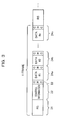
- FIG. 3 is a diagram illustrating an example of a frame format.
- the wireless base station 11 and the mobile terminal 12 transmit and receive data based on the frame format illustrated in FIG. 3 .
- an RS 21, control information 22, and a CRC 23 of the control information 22 are allocated to one frame.
- one frame is divided into a plurality of segments 24a, 24b, ..., 24n, and the data encoded in the unit of segments 24a, 24b, ..., and 24n and the CRC of the data are allocated.
- the data allocated to the segments 24a, 24b, ..., and 24n is decoded in the unit of segments 24a, 24b, ..., and 24n.
- the wireless base station 11 determines the transmission rate (modulation scheme and coding rate) of data transmitted in the unit of segments 24a, 24b, ..., and 24n according to the distance from the RS 21.
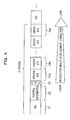
- FIG. 4 is a diagram illustrating an example of a frame format in which the transmission rate is variable between segments. As illustrated in FIG. 4 , the transmission rate of data is set high in the segment 24a near the RS 21. On the other hand, the transmission rate of data is set low in the segment 24n far from the RS 21.
- the difference between a channel estimation value obtained using the RS 21 and the actual channel estimation value in the segment 24a is small. Therefore, the decoding accuracy of data of the segment 24a is high, and data in high transmission rate (low redundancy) can be accurately decoded.
- the difference between a channel estimation value obtained using the RS 21 and the actual channel estimation value in the segment 24n is large. Therefore, the decoding accuracy of data of the segment 24n is low, and the data is transmitted and received in low transmission rate (high redundancy) to allow accurate decoding.
- the modulation scheme of the segment 24a at a location closest to the RS 21 is 16QAM (Quadrature Amplitude Modulation), and the coding rate is 0.6.
- the modulation scheme of the segment 24n at a location farthest from the RS 21 is QPSK (Quadrature Phase Shift Keying), and the coding rate is 0.5.
- FIG. 5 is a block diagram of a configuration of the wireless base station 11.
- the wireless base station 11 includes a data generating unit 31, a control information generating unit 32, an RS generating unit 33, a receiving unit 34, an uplink stream transmission frame demodulating/decoding unit 35, a scheduler 36, a data framing unit 37, modulating units 38 and 40, a control information framing unit 39, a multiplexing unit 41, and a transmitting unit 42.
- the data generating unit 31 generates data to be transmitted to the mobile terminal 12.
- the control information generating unit 32 generates control information to be transmitted to the mobile terminal 12.
- the RS generating unit 33 generates an RS to be transmitted to the mobile terminal 12.
- the receiving unit 34 receives a wireless signal wirelessly transmitted from the mobile terminal 12 through an antenna Rx.
- An MCS Modulation and Coding Scheme
- the MCS is information including a modulation scheme and a coding rate of an uplink stream wireless signal transmitted by the mobile terminal 12.
- the uplink stream transmission frame demodulating/decoding unit 35 demodulates and decodes an uplink stream wireless signal received by the receiving unit 34 based on the MCS informed from the scheduler 36.
- the data received from the mobile terminal 12 includes control information.
- the control information includes information such as ACK/NACK (Acknowledgement/Negative Acknowledgement) information indicating a retransmission request of data and CQI (Channel Quality Indicator) information.
- ACK/NACK Acknowledgement/Negative Acknowledgement
- CQI Channel Quality Indicator
- the scheduler 36 schedules downlink stream and uplink stream data.
- the scheduler 36 also determines the modulation scheme and the coding rate (MCS: Modulation and coding scheme) of the mobile terminal 12 when scheduling the uplink stream data and informs the modulation scheme and the coding rate to the uplink stream transmission frame demodulating/decoding unit 35.
- MCS Modulation and coding scheme
- the scheduler 36 further outputs the uplink stream modulation scheme and the coding rate as control information to the control information framing unit 39 to inform the uplink stream modulation scheme and the coding rate to the mobile terminal 12.
- the scheduler 36 determines rate instruction information of downlink stream data to be transmitted to the mobile terminal 12.
- the rate instruction information is information indicating the transmission rate of the segments 24a, 24b, ..., and 24n, and is information-such as the transmission rate of the segment 24a being 16QAM with a coding rate of 0.6, and the transmission rate of the segment 24b being 16QAM with a coding rate of 0.5.
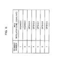
- FIG. 6 is a diagram illustrating a data configuration example of the rate instruction information.
- the rate instruction information includes a field of segment number and a field of MCS.
- the segment number corresponds to, for example, the segments 24a, 24b, ..., and 24n illustrated in FIG. 4 .
- the rate instruction information illustrated in FIG. 6 is stored in a storage device (storage unit)(not illustrated), and the scheduler 36 acquires the rate instruction information from the storage device. There are a plurality of patterns in the rate instruction information, and a plurality of pieces of information are stored in the storage device.
- the scheduler 36 refers to the storage device based on CQI information of the control information outputted from the uplink stream transmission frame demodulating/decoding unit 35 to acquire predetermined rate instruction information from among the plurality of pieces of the rate instruction information. Specifically, the scheduler 36 determines the rate instruction information according to the wireless quality, such as fading variation. The scheduler 36 outputs the determined rate instruction information to the data framing unit 37 and the modulating unit 38. The scheduler 36 also informs the determined rate instruction information as control information to the control information framing unit 39 to inform the rate instruction information to the mobile terminal 12.
- the scheduler 36 outputs the ACK/NACK information of the control information outputted from the uplink stream transmission frame demodulating/decoding unit 35 to the data generating unit 31, the control information generating unit 32, and the RS generating unit 33.
- the data generating unit 31, the control information generating unit 32, and the RS generating unit 33 generate retransmission data according to the ACK/NACK information.
- the scheduler 36 When the uplink stream data is not appropriately received, the scheduler 36 outputs the control information of that fact to the control information framing unit 39 to request the mobile terminal 12 for retransmission.
- the rate instruction information is inputted to the data framing unit 37 from the scheduler 36.
- the data framing unit 37 separates the data outputted from the data generating unit 31 into segments and encodes the data based on the segment numbers and the coding rates included in the rate instruction information. Examples of the encoding include Reed-Solomon encoding and turbo encoding.
- the rate instruction information is inputted to the modulating unit 38 from the scheduler 36.
- the modulating unit 38 modulates the data outputted from the data framing unit 37 segment by segment based on the segment numbers and the coding rates included in the rate instruction information.
- the control information framing unit 39 encodes the control information outputted from the control information generating unit 32 and the control information outputted from the scheduler 36.
- the modulating unit 40 modulates the control information outputted from the control information framing unit 39.
- the coding rate and the modulation scheme of the control information are generally fixed, the coding rate and the modulation scheme may be changed by an instruction from a higher-level apparatus, such as an RNC (Radio Network Control), of the wireless base station 11.
- RNC Radio Network Control
- the multiplexing unit 41 multiplexes the data outputted from the modulating unit 38, the control information outputted from the modulating unit 40, and the RS outputted from the RS generating unit 33, and outputs them to the transmitting unit 42.
- the multiplexing unit 41 outputs a frame format, as illustrated in FIG. 4 .
- the transmitting unit 42 converts the data outputted from the multiplexing unit 41 to a wireless signal and wirelessly transmits the signal to the mobile terminal 12 through the antenna Tx.
- FIG. 7 is a block diagram of a configuration of the terminal 12. As illustrated in FIG. 7 , the mobile terminal 12 includes a receiving unit 51, a separating unit 52, a channel estimating unit 53, demodulating units 54 and 56, a control information decoding unit 55, a data decoding unit 57, an error detecting unit 58, an uplink stream control information generating unit 59, an uplink stream transmission frame framing unit 60, and a transmitting unit 61.
- the receiving unit 51 receives the wireless signal wirelessly transmitted from the wireless base station 11 through the antenna Rx.
- the separating unit 52 separates the wireless signal received by the receiving unit 51 into an RS, control information, and data.
- the channel estimating unit 53 calculates a channel estimation value based on the RS separated by the separating unit 52.
- the demodulating unit 54 demodulates the control information based on the channel estimation value calculated by the channel estimating unit 53.
- the control information decoding unit 55 decodes the demodulated control information.
- the demodulating unit 56 demodulates the data separated by the separating unit 52 based on the channel estimation value calculated by the channel estimating unit 53 and the control information decoded by the control information decoding unit 55.
- the control information includes rate instruction information, and the demodulating unit 56 demodulates the segmented data according to the rate instruction information.
- the demodulating unit 56 demodulates the data segment by segment based on the rate instruction information.
- the data decoding unit 57 decodes the segmented data based on the rate instruction information included in the control information. Thus, the data decoding unit 57 decodes the data segment by segment based on the rate instruction information.
- the error detecting unit 58 detects an error of data based on the CRC of the decoded data.
- the uplink stream control information generating unit 59 generates uplink stream control information based on the control information decoded by the control information decoding unit 55.
- the uplink stream transmission frame framing unit 60 generates a frame to be transmitted to the wireless base station 11.
- An RS, control information, and data are inputted to the uplink stream transmission frame framing unit 60, and an uplink stream transmission frame is generated.
- the transmitting unit 61 converts the data outputted from the uplink stream transmission frame framing unit 60 to a wireless signal and wirelessly transmits the signal to the base station 11 through the antenna Tx.
- the wireless base station 11 segments and transmits the data in the description of FIGS. 5 and 7
- the mobile terminal 12 can also segment and transmit the data.
- the scheduler 36 of the wireless base station 11 also determines the rate instruction information of the mobile terminal 12. As in the description of FIG. 6 , the rate instruction information of the mobile terminal 12 is stored in the storage device, and the scheduler 36 determines the rate instruction information of the mobile terminal 12 with reference to the storage device.
- the wireless base station 11 inputs the determined rate instruction information of the mobile terminal 12 into the control information and transmits the information to the mobile terminal 12.
- the mobile terminal 12 segments the data based on the received rate instruction information, generates data in the frame format illustrated in FIG. 4 , and wirelessly transmits the data to the wireless base station 11.
- the uplink stream transmission frame framing unit 60 of FIG. 7 includes a data framing unit and a modulating unit similar to the data framing unit 37 and the modulating unit 38 of FIG. 5 .
- the data framing unit and the modulating unit segment, encode, and modulate the data based on the rate instruction information included in the control information decoded by the control information decoding unit 55.
- the wireless base station 11 and the mobile terminal 12 segment the data and make the transmission rate variable in each segmented data. This enables maintaining throughput even in a poor channel environment.
- the data is segmented, and the transmission rate of the segmented data is variable.
- the transmission power of the segmented data is variable.
- FIG. 8 is a diagram illustrating an example of a frame format according to the second embodiment.
- an RS 71, control information 72, and a CRC 73 of the control information 72 are allocated to one frame.
- one frame is divided into a plurality of segments 74a, 74b, ..., and 74n, and the data encoded in the unit of segments 74a, 74b, ..., and 74n and the CRC of the data (not illustrated) are allocated.
- the data allocated to the segments 74a, 74b, ..., and 74n is decoded in the unit of segments 74a, 74b, ..., and 74n.
- the difference between a channel estimation value obtained using the RS 71 and the actual channel estimation value in the segment 74a is small. Therefore, the decoding accuracy of data of the segment 74a is high, and data in low transmission power can be accurately decoded.
- the difference between a channel estimation value obtained using the RS 71 and the actual channel estimation value in the segment 74n is large. Therefore, the decoding accuracy of data of the segment 74a is low, and the data is transmitted in high transmission power to allow accurate decoding.
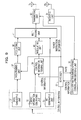
- FIG. 9 is a block diagram of a configuration of the wireless base station.
- the scheduler 81 determines power instruction information of data to be transmitted to the mobile terminal 12.
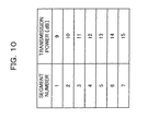
- the power instruction information is information indicating the transmission power of the segments 74a, 74b, ..., and 74n and is information of the transmission power, such as the segment 74a at 9 dB and the segment 74b at 10 dB.
- FIG. 10 is a diagram illustrating a data configuration example of the power instruction information.
- the power instruction information includes a field of segment number and a field of transmission power.
- the segment number corresponds to, for example, the segments 74a, 74b, ..., and 74n illustrated in FIG. 8 .
- the power instruction information illustrated in FIG. 10 is stored in a storage device, and the scheduler 81 acquires the power instruction information from the storage device. There are a plurality of patterns in the power instruction information, and a plurality of pieces of information are stored in the storage device (storage unit).
- the scheduler 81 refers to the storage device based on CQI information of the control information outputted from the uplink stream transmission frame demodulating/decoding unit 35 to acquire the power instruction information. Specifically, the scheduler 81 determines predetermined power instruction information according to the wireless quality, such as fading variation. The scheduler 81 outputs the determined power instruction information to the transmitting unit 82.
- the power instruction information is inputted to the data framing unit 37 from the scheduler 81.
- the data framing unit 37 segments and encodes the data based on the segment numbers included in the power instruction information.
- the power instruction information is inputted to the transmitting unit 82 from the scheduler 81.
- the transmitting unit 82 makes the power of data of the segments outputted from the multiplexing unit 41 variable based on the segment numbers and the transmission power included in the power instruction information.
- FIG. 9 Other processes of FIG. 9 are similar to those in FIG. 5 .
- the power instruction information is not included in the downlink stream control information to be transmitted to the mobile terminal 12. This is because the mobile terminal 12 can perform decoding and demodulation without the power instruction information.
- the block configuration of the mobile terminal 12 is the same as in FIG. 7 .
- the mobile terminal 12 can also segment and transmit the data.
- the scheduler 81 of the wireless base station 11 also determines the power instruction information of the mobile terminal 12.
- the power instruction information of the mobile terminal 12 is stored in the storage device, and the scheduler 81 determines the power instruction information of the mobile terminal 12 with reference to the storage device.
- the wireless base station 11 inputs the determined power instruction information of the mobile terminal 12 into the control information and transmits the information to the mobile terminal 12.
- the mobile terminal 12 segments the data based on the received power instruction information, generates data in the frame format illustrated in FIG. 8 , and wirelessly transmits the data to the wireless base station 11.
- the uplink stream transmission frame framing unit 60 of FIG. 7 includes the same functions as the data framing unit 37 of FIG. 9 and segments and encodes the data based on the power instruction information included in the control information decoded by the control information decoding unit 55.
- the transmitting unit 61 includes the same functions as the transmitting unit 82 of FIG. 9 and makes the transmission power of the segmented data variable based on the power instruction information included in the control information decoded by the control information decoding unit 55.
- the wireless base station 11 and the mobile terminal 12 segment the data and make the transmission power variable in each segmented data. This enables maintaining throughput even in a poor channel environment.
- the transmission rate of the segmented data can be varied so that the transmission rate becomes low.
- the transmission rate of the segmented data can be varied so that the transmission rate becomes high.
- a pseudo RS will be described first.
- FIG. 11 is a diagram for explaining the pseudo RS.
- FIG. 11 illustrates frames 91 and 92.
- the frame 92 follows the frame 91.
- the data of the frame 91 is already known when the wireless base station 11 or the mobile terminal 12 receives the frame 92 from a partner apparatus. Therefore, the wireless base station 11 or the mobile terminal 12 can artificially use part or all of the control information and data of the frame 91 as an RS of the frame 92.
- the wireless base station 11 or the mobile terminal 12 uses not only the RS of the frame 92, but also the known control information and the data of the frame 91, as a pseudo RS to perform the channel estimation of the frame 92.
- the known data or the like of the previously received frame is used as a pseudo RS to artificially extend the width of the RS, thereby preventing the degradation of the channel estimation.
- the control information and the data may not be used as a pseudo RS. In this case, the width of the pseudo RS is shortened, and the channel estimation is degraded.
- FIG. 12 is a diagram illustrating an example of a frame format according to a third embodiment.
- an RS 101, control information 102, and a CRC 103 of the control information 102 are allocated to one frame.
- one frame is divided into a plurality of segments 104a, 104b, ..., and 104n, and the data encoded in the unit of segments 104a, 104b, ..., and 104n and the CRC of the data (not illustrated) are allocated.
- the data allocated to the segments 104a, 104b, ..., and 104n is decoded in the unit of segments 104a, 104b, ..., and 104n.
- the transmission rate is set low so that reliable encoding is performed without error.
- the transmission rate is set high with increasing distance from the RS 101.
- the modulation scheme of the segment 104a closest to the RS 101 is QPSK, and the coding rate is 0.5.
- the modulation scheme of the segment 104n farthest from the RS 101 is 16QAM, and the coding rate is 0.6.
- the data of the segment near the RS 101 is reliably decoded by reducing the transmission rate of the segment near the RS 101.
- This enables reliably extending the width of the pseudo RS even in a poor channel environment, thereby preventing the degradation of the channel estimation and maintaining throughput.
- FIG. 13 is a diagram illustrating FIG. 12 with time-frequency axes.
- the horizontal axis of FIG. 13 denotes time, and the vertical axis denotes frequency.
- the transmission rate of the data of the segment near the RS is low.
- the transmission rate of the data of the segment at the location far from the RS is high. If there is no error in decoding of nearby data, the range of the areas of the RS illustrated in FIG. 13 spreads to the central part of the data in high transmission rate based on the pseudo RS. This enables preventing the degradation of the channel estimation of the part of the data in high transmission rate illustrated in FIG. 13 .
- FIG. 14 is a diagram illustrating a data configuration example of the rate instruction information. As illustrated in FIG. 14 , the rate instruction information includes a field of segment number and a field of MCS.
- the segment number corresponds to, for example, the segments 104a, 104b, ..., and 104n illustrated in FIG. 12 .
- the rate instruction information illustrated in FIG. 14 is stored in a storage device, and the scheduler 36 acquires the rate instruction information from the storage device. There are a plurality of patterns in the rate instruction information, and a plurality of pieces of information are stored in the storage device.
- FIG. 15 is a block diagram of a configuration of the mobile terminal.
- the mobile terminal 12 includes a pseudo-channel estimating unit 111 and a channel estimation value combining unit 112.
- the pseudo-channel estimating unit 111 sets the decoded control information and the data as a pseudo RS to calculate a pseudo-channel estimation value.
- the channel estimation value combining unit 112 combines the channel estimation value calculated by the channel estimating unit 53 and the pseudo-channel estimation value calculated by the pseudo-channel estimating unit 111 to calculate a channel estimation value.
- the channel estimating unit 53 calculates the channel estimation value based on the RS of the currently receiving frame.
- the pseudo-channel estimating unit 111 calculates the pseudo-channel estimation value based on the already known control information and data of the previous frame. For example, the channel estimating unit 53 uses the RS of the frame 92 illustrated in FIG. 11 to calculate the channel estimation value.
- the pseudo-channel estimating unit 111 uses the control information and the data of the frame 91 to calculate the pseudo-channel estimation value.
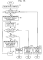
- FIG. 16 is a flow chart of a pseudo RS process of the mobile terminal.
- the mobile terminal 12 calculates the channel estimation value according to the following steps.
- step S1 the mobile terminal 12 decodes the control information.
- step S2 the mobile terminal 12 determines whether decoding of the control information has been performed without error. If the decoding has been performed without error, the process proceeds to step S3. If there is an error in decoding, the process proceeds to step S11.
- step S3 the mobile terminal 12 regards the control information of the frame as an RS and updates the pseudo-channel estimation value.
- step S4 the mobile terminal 12 decodes the n-th data of frame (n: positive integer between 1 to N, N: the number of segments).
- step S5 the mobile terminal 12 determines whether the n-th data block has been decoded without error. If the decoding has been performed without error, the process proceeds to step S6. If there is an error in decoding, the process proceeds to step S10.
- step S6 the mobile terminal 12 compares the values of n and N. If the value of n is smaller than N, the process proceeds to step S7. If the value of n is equal to or greater than N, the process proceeds to step S9. In step S7, the mobile terminal 12 also regards the information of the n-th data block as the RS and updates the pseudo-channel estimation value.
- the channel estimation value combining unit 112 combines the pseudo-channel estimation value with the channel estimation value calculated by the channel estimating unit 53.
- step S8 the mobile terminal 12 adds 1 to the value of n, and the process proceeds to step S4.
- step S9 the mobile terminal 12 returns the ACK to the transmission side (wireless base station 11).
- step S10 the mobile terminal 12 returns the NACK to the transmission side and requests retransmission of data.
- step S11 the mobile terminal 12 returns the NACK to the transmission side and requests retransmission of data.
- reducing the transmission rate of the segment near the RS and reliably decoding the data of the segment near the RS enable reliably extending the width of the pseudo RS, thereby preventing the degradation of the channel estimation and maintaining throughput.
- the wireless base station 11 may also include the pseudo RS.
- the uplink stream transmission frame demodulating/decoding unit 35 illustrated in FIG. 5 includes the channel estimating unit 53, the pseudo-channel estimating unit 111, and the channel estimation value combining unit 112 of FIG. 15 .
- the uplink stream transmission frame demodulating/decoding unit 35 calculates the pseudo-channel estimation value from the received control information and data and demodulates and decodes the data.
- the transmission rate of the segmented data can be varied so that the transmission rate becomes high.
- the transmission power of the segmented data can be varied so that the transmission power becomes low.
- FIG. 17 is a diagram illustrating an example of a frame format according to the fourth embodiment.
- an RS 121, control information 122, and a CRC 123 of the control information 122 are allocated to one frame.
- one frame is divided into a plurality of segments 124a, 124b, ..., and 124n, and the data encoded in the unit of segments 124a, 124b, ..., and 124n and the CRC of the data are allocated.
- the data allocated to the segments 124a, 124b, ..., and 124n is decoded in the unit of segments 124a, 124b, ..., and 124n.
- the transmission power is set high so that reliable encoding is performed without error.
- the transmission power is set low with increasing distance from the RS 121.
- the data of the segment near the RS 121 is reliably decoded by increasing the transmission power of the segment near the RS 121. This enables reliably extending the width of the pseudo RS even in the worst channel environment, thereby preventing the degradation of the channel estimation.
- FIG. 18 is a diagram illustrating FIG. 17 with time-frequency axes.
- the horizontal axis of FIG. 18 denotes time, and the vertical axis denotes frequency.
- the transmission power of the data of the segment near the RS is high.
- the transmission power of the data of the segment at a location far from the RS is low. If there is no error in decoding of nearby data, the range of the areas of the RS illustrated in FIG. 18 spreads to the central part of the data in low transmission power based on the pseudo RS. This enables preventing the degradation of the channel estimation of the part of the data in low transmission power illustrated in FIG. 18 .
- FIG. 19 is a diagram illustrating a data configuration example of the power instruction information. As illustrated in FIG. 19 , the power instruction information includes a field of segment number and a field of transmission power.
- the segment number corresponds to, for example, the segments 124a, 124b, ..., and 124n illustrated in FIG. 17 .
- the power instruction information illustrated in FIG. 19 is stored in a storage device, and the scheduler 81 acquires the power instruction information from the storage device. There are a plurality of patterns in the power instruction information, and a plurality of pieces of information are stored in the storage device.
- the configuration of the mobile terminal 12 is the same as in FIG. 15 .
- the wireless base station 11 may also include the pseudo RS.
- the uplink stream transmission frame demodulating/decoding unit 35 illustrated in FIG. 5 includes the channel estimating unit 53, the pseudo-channel estimating unit 111, and the channel estimation value combining unit 112 of FIG. 15 .
- the uplink stream transmission frame demodulating/decoding unit 35 calculates the pseudo-channel estimation value from the received control information and data and demodulates and decodes the data.
- the number of segments can be varied according to the wireless quality.
- the number of the segments 24a, 24b, ..., and 24n illustrated in FIG. 3 can be varied.
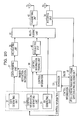
- FIG. 20 is a block diagram of a configuration of the wireless base station according to the fifth embodiment.
- a scheduler 131 outputs division instruction information to the data framing unit 37, the information including the number of segments to which data will be allocated.
- the data framing unit 37 divides the data into a predetermined number of pieces based on the number of segments of the division instruction information and encodes the data.
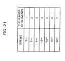
- FIG. 21 is a diagram illustrating a data configuration example of the division instruction information.
- the division instruction information includes a field of SIR (Signal to Interference Ratio) and a field of the number of segments. The number of segments increases as the value of the SIR decreases.
- the division instruction information is stored in a storage device.
- the scheduler 131 acquires the division instruction information from the storage device based on the wireless quality such as the SIR.
- the SIR is included in the CQI information from the uplink stream transmission frame demodulating/decoding unit 35.
- the scheduler 131 outputs the division instruction information acquired based on the SIR to the data framing unit 37.
- the scheduler 131 also outputs the acquired division instruction information to the control information framing unit 39 as control information.
- the mobile terminal 12 is the same as in FIG. 7 .
- the demodulating unit 56 and the data decoding unit 57 demodulate and decode the segmented data segment by segment based on the division instruction information included in the control information.
- the mobile terminal 12 can also make the number of segments of the data variable.
- the scheduler 131 of the wireless base station 11 also determines the division instruction information of the mobile terminal 12.
- the division instruction information of the mobile terminal 12 is stored in the storage device, and the scheduler refers to the storage device to determine the division instruction information of the mobile terminal 12.
- the wireless base station 11 inputs the determined division instruction information of the mobile terminal 12 into the control information and transmits the information to the mobile terminal 12.
- the mobile terminal 12 segments the data based on the division instruction information included in the received control information and wirelessly transmits the data to the wireless base station 11.
- making the number of segments variable enables improving the channel estimation accuracy by increasing the number of segments in a poor propagation channel environment.
- the number of segments is decreased to reduce the CRC bits, thereby ensuring throughput.
- the fifth embodiment can also be applied to the first to fourth embodiments.
- the transmission rate and the transmission power can be varied, and the number of segments can also be varied.
- the coding rate is calculated by formulas.
- the wireless base station 11 and the mobile terminal 12 include a block configuration similar to that in the first and third embodiments.
- the wireless base station 11 includes an AMC (Auto Modulation Control) and a transmission rate calculating unit.
- AMC Auto Modulation Control
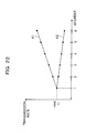
- FIG. 22 is a diagram illustrating a relationship between the segments and the transmission rate.
- the horizontal axis of FIG. 22 denotes numbers indicating locations of the segments.
- the segments 24a and 24b of FIG. 3 correspond to 1 and 2 on the horizontal axis of FIG. 22 .
- the vertical axis denotes the transmission rate.
- a straight line A1 of FIG. 22 illustrates an example in which the transmission rate becomes higher with increasing distance from the RS to the location of the segment.
- a straight line A2 illustrates an example in which the transmission rate becomes lower with increasing distance from the RS to the location of the segment.
- rate(1) denotes the transmission rate of the leading segment determined by the AMC.
- the calculation of the slopes of the straight lines A1 and A2 of the transmission rate calculating unit will be described.
- the number of bits of the data to be transmitted is the same as when the coding rate is not changed (normal data transmission).
- the coding rate in the n-th segment is defined as rate(n).
- the slope to be calculated is defined as r, the number of bits per segment is defined as T, the coding rate is defined as r0, and the number of segments is defined as N.
- rate n rate 1 + r ⁇ n - 1
- the slope r is obtained by assigning formula (2) to formula (1).
- the scheduler 36 informs the transmission rate calculated by the transmission rate calculating unit to the data framing unit 37 and the modulating unit 38. As a result, the coding rate can be determined segment by segment.
- the coding rate is changed only in the time direction in the description above, the same can also be obtained in the frequency direction. Two dimensional expansion of time and frequency is also possible. In this way, the transmission rate of segment can be determined by calculating the transmission rate by computation.
- the number of times of code multiplexing may also be variable in each segment in the CDMA system.
- Code sequences orthogonal to each other are prepared for each user in the CDMA system. After normal demodulation, the spreading codes are multiplied, and the pieces of the user data are combined. On the receiving side, multiplying (dispreading) the spreading codes that are independent for each user enables extracting data user by user.
- the number of times of multiplexing of users is called a number of times of code multiplexing.
- the various features may be implemented in hardware, or as software modules running on one or processors. Features of one aspect may be applied to any of the other aspects.
- the invention also provides a computer program or a computer program product for carrying out any of the methods described herein, and a computer readable medium having stored thereon a program for carrying out any of the methods described herein.
- a computer program embodying the invention may be stored on a computer-readable medium, or it could, for example, be in the form of a signal such as a downloadable data signal provided from an Internet website, or it could be in any other form.
Landscapes
- Engineering & Computer Science (AREA)
- Signal Processing (AREA)
- Computer Networks & Wireless Communication (AREA)
- Quality & Reliability (AREA)
- Power Engineering (AREA)
- Mobile Radio Communication Systems (AREA)
- Time-Division Multiplex Systems (AREA)
- Digital Transmission Methods That Use Modulated Carrier Waves (AREA)
- Detection And Prevention Of Errors In Transmission (AREA)
Abstract
Description
- The present invention relates to a wireless communication apparatus that transmits a wireless signal and a wireless communication apparatus that receives a wireless signal.
- In wireless communication, a transmission frame format consisted of a plurality of blocks is generally used. For example, one frame of the transmission frame format includes an RS (Reference Signal), control information, a CRC (Cyclic Redundancy Check) of the control information, data, and a CRC of the data.
- The improvement of the channel estimation accuracy remains a problem in wireless communication.
The RSs are discretely arranged in the current 3GPP (3rd Generation Partnership Project). Therefore, the accuracy of the channel estimation of control information and data between RSs is improved by averaging the RSs or performing linear interpolation or other processes. However, even if such a method is used, the following capability is reduced when the channel fluctuation is fast, and the degradation of the channel estimation accuracy is inevitable. - Consequently, an estimation method of propagation characteristics of received signals is known, in which part of properly decoded control information or data is regarded equivalent to an RS to decode sequentially transmitted data (see, for example, Japanese Laid-Open Patent Publication No.
2003-115783 - For example, assuming that the control information is properly decoded in a certain frame, the control information can be regarded equivalent to the RS because the control information is known information. Therefore, the RS of the frame to be transmitted next and the known control information are used to artificially widen the width of the RS, thereby preventing the degradation of the channel estimation of data to be transmitted next.
- However, in the conventional channel estimation method, if there is an error in decoding of the previous control information or the like, the control information or the like may not be artificially used as the RS. Therefore, the method may not function in a poor channel environment, and the throughput may be reduced.
It is desirable to provide a wireless communication apparatus capable of maintaining the throughput even in a poor channel environment. - According to an aspect of the embodiments, a wireless communication apparatus transmits a wireless signal, the wireless communication apparatus including a dividing unit that divides data transmitted in a data area of a frame format of the wireless signal into a plurality of segments. The wireless communication apparatus includes an encoding unit that encodes the data segmented by the dividing unit segment by segment.
Advantages of the embodiments may be realized and attained by means of the elements and combinations particularly pointed out in the claims.
It is to be understood that both the foregoing general description and the following detailed description are exemplary and explanatory only and are not restrictive of the invention, as claimed. -
-
FIG. 1 is a diagram for explaining an overview of a wireless communication apparatus; -
FIG. 2 is a diagram illustrating a configuration example of the wireless communication system according to a first embodiment; -
FIG. 3 is a diagram illustrating an example of a frame format; -
FIG. 4 is a diagram illustrating an example of a frame format in which the transmission rate is variable between segments; -
FIG. 5 is a block diagram of a configuration of a wireless base station; -
FIG. 6 is a diagram illustrating a data configuration example of rate instruction information; -
FIG. 7 is a block diagram of a configuration of a mobile terminal; -
FIG. 8 is a diagram illustrating an example of a frame format according to a second embodiment; -
FIG. 9 is a block diagram of a configuration of the wireless base station; -
FIG. 10 is a diagram illustrating a data configuration example of power instruction information; -
FIG. 11 is a diagram for explaining a pseudo RS; -
FIG. 12 is a diagram illustrating an example of a frame format according to a third embodiment; -
FIG. 13 is a diagram illustratingFIG. 12 with time-frequency axes; -
FIG. 14 is a diagram illustrating a data configuration example of rate instruction information; -
FIG. 15 is a block diagram of a configuration of the mobile terminal; -
FIG. 16 is a flow chart of a pseudo RS process of the mobile terminal; -
FIG. 17 is a diagram illustrating an example of a frame format according to a fourth embodiment; -
FIG. 18 is a diagram illustratingFIG. 17 with time-frequency axes; -
FIG. 19 is a diagram illustrating a data configuration example of power instruction information; -
FIG. 20 is a block diagram of a configuration of the wireless base station according to a fifth embodiment; -
FIG. 21 is a diagram illustrating a data configuration example of division instruction information; and -
FIG. 22 is a diagram illustrating the relationship between segments and transmission rate. -
FIG. 1 is a diagram for explaining an overview of a wireless communication apparatus. Awireless communication apparatus 1 illustrated inFIG. 1 is a wireless communication apparatus on the data transmitting side. Awireless communication apparatus 2 is a wireless communication apparatus on the data receiving side.FIG. 1 depicts a frame format of a wireless signal transmitted from thewireless communication apparatus 1 to thewireless communication apparatus 2. - The
wireless communication apparatus 1 includes dividingunit 1a andencoding unit 1b. Thewireless communication apparatus 2 includes receivingunit 2a anddecoding unit 2b.
The dividingunit 1a of thewireless communication apparatus 1 divides data transmitted in adata area 3 of the frame format of the wireless signal into a plurality of segments. - The
encoding unit 1b encodesdata unit 1a, segment by segment.
Thereceiving unit 2a of thewireless communication apparatus 2 receives the wireless signal in the frame format, in which data of thedata area 3 is divided into a plurality of segments. - The
decoding unit 2b decodesdata receiving unit 2a, segment by segment.
After segmenting and encoding the transmission data on the transmission side as described, the transmission rate of thedata data 3a of the segment near the RS can be set high, and the transmission rate of thedata 3n of the segment far from the RS can be set low. - As a result, the
data 3n of the segment at a location away from the RS can also be appropriately decoded on the receiving side even in a poor channel environment because the transmission rate is low.
In this way, segmenting and encoding of data enables maintaining throughput even in a poor channel environment. - A first embodiment will be described in detail with reference to the drawings.
FIG. 2 is a diagram illustrating a configuration example of a wireless communication system according to the first embodiment.FIG. 2 illustrates awireless base station 11 and amobile terminal 12. Themobile terminal 12 is, for example, a cellular phone. Thewireless base station 11 and themobile terminal 12 can apply various communication systems, such as TDMA (Time Division Multiple Access), FDMA (Frequency Division Multiple Access), and CDMA (Code Division Multiple Access). -
FIG. 3 is a diagram illustrating an example of a frame format. Thewireless base station 11 and themobile terminal 12 transmit and receive data based on the frame format illustrated inFIG. 3 .
As illustrated inFIG. 3 , anRS 21, controlinformation 22, and aCRC 23 of thecontrol information 22 are allocated to one frame. In a data area where data is allocated, one frame is divided into a plurality ofsegments segments segments segments - The
wireless base station 11 determines the transmission rate (modulation scheme and coding rate) of data transmitted in the unit ofsegments RS 21.
FIG. 4 is a diagram illustrating an example of a frame format in which the transmission rate is variable between segments. As illustrated inFIG. 4 , the transmission rate of data is set high in thesegment 24a near theRS 21. On the other hand, the transmission rate of data is set low in thesegment 24n far from theRS 21. - In the
segment 24a at a location near theRS 21, the difference between a channel estimation value obtained using theRS 21 and the actual channel estimation value in thesegment 24a is small. Therefore, the decoding accuracy of data of thesegment 24a is high, and data in high transmission rate (low redundancy) can be accurately decoded. - Meanwhile, in the
segment 24n at a location far from theRS 21, the difference between a channel estimation value obtained using theRS 21 and the actual channel estimation value in thesegment 24n is large. Therefore, the decoding accuracy of data of thesegment 24n is low, and the data is transmitted and received in low transmission rate (high redundancy) to allow accurate decoding. - In the example of
FIG. 4 , the modulation scheme of thesegment 24a at a location closest to theRS 21 is 16QAM (Quadrature Amplitude Modulation), and the coding rate is 0.6. The modulation scheme of thesegment 24n at a location farthest from theRS 21 is QPSK (Quadrature Phase Shift Keying), and the coding rate is 0.5. - Making the transmission rate of the
segments RS 21 enables maintaining throughput even in a poor channel environment. - Although both of the modulation multi-level number and the coding rate are variable in
Fig. 4 , one of them may be fixed while only the other is variable. InFIG. 4 , the CRC is not illustrated.
FIG. 5 is a block diagram of a configuration of thewireless base station 11. As illustrated inFIG. 5 , thewireless base station 11 includes adata generating unit 31, a controlinformation generating unit 32, anRS generating unit 33, a receivingunit 34, an uplink stream transmission frame demodulating/decoding unit 35, ascheduler 36, adata framing unit 37, modulatingunits information framing unit 39, a multiplexingunit 41, and a transmittingunit 42. - The
data generating unit 31 generates data to be transmitted to themobile terminal 12. The controlinformation generating unit 32 generates control information to be transmitted to themobile terminal 12. TheRS generating unit 33 generates an RS to be transmitted to themobile terminal 12. - The receiving
unit 34 receives a wireless signal wirelessly transmitted from themobile terminal 12 through an antenna Rx.
An MCS (Modulation and Coding Scheme) is inputted to the uplink stream transmission frame demodulating/decoding unit 35 from thescheduler 36. The MCS is information including a modulation scheme and a coding rate of an uplink stream wireless signal transmitted by themobile terminal 12. The uplink stream transmission frame demodulating/decoding unit 35 demodulates and decodes an uplink stream wireless signal received by the receivingunit 34 based on the MCS informed from thescheduler 36. - The data received from the
mobile terminal 12 includes control information. The control information includes information such as ACK/NACK (Acknowledgement/Negative Acknowledgement) information indicating a retransmission request of data and CQI (Channel Quality Indicator) information. The uplink stream transmission frame demodulating/decoding unit 35 outputs the demodulated control information to thescheduler 36. - The
scheduler 36 schedules downlink stream and uplink stream data. Thescheduler 36 also determines the modulation scheme and the coding rate (MCS: Modulation and coding scheme) of themobile terminal 12 when scheduling the uplink stream data and informs the modulation scheme and the coding rate to the uplink stream transmission frame demodulating/decoding unit 35. Thescheduler 36 further outputs the uplink stream modulation scheme and the coding rate as control information to the controlinformation framing unit 39 to inform the uplink stream modulation scheme and the coding rate to themobile terminal 12. - The
scheduler 36 determines rate instruction information of downlink stream data to be transmitted to themobile terminal 12. The rate instruction information is information indicating the transmission rate of thesegments segment 24a being 16QAM with a coding rate of 0.6, and the transmission rate of thesegment 24b being 16QAM with a coding rate of 0.5. -
FIG. 6 is a diagram illustrating a data configuration example of the rate instruction information. As illustrated inFIG. 6 , the rate instruction information includes a field of segment number and a field of MCS.
The segment number corresponds to, for example, thesegments FIG. 4 . The smaller the segment number, the closer is the corresponding segment to theRS 21, and the larger the number, the farther is the corresponding segment to theRS 21. Therefore, the smaller the segment number, the higher is the transmission rate, and the larger the segment number, the lower is the transmission rate. - The rate instruction information illustrated in
FIG. 6 is stored in a storage device (storage unit)(not illustrated), and thescheduler 36 acquires the rate instruction information from the storage device. There are a plurality of patterns in the rate instruction information, and a plurality of pieces of information are stored in the storage device. -
FIG. 5 will be further described. Thescheduler 36 refers to the storage device based on CQI information of the control information outputted from the uplink stream transmission frame demodulating/decoding unit 35 to acquire predetermined rate instruction information from among the plurality of pieces of the rate instruction information. Specifically, thescheduler 36 determines the rate instruction information according to the wireless quality, such as fading variation. Thescheduler 36 outputs the determined rate instruction information to thedata framing unit 37 and the modulatingunit 38. Thescheduler 36 also informs the determined rate instruction information as control information to the controlinformation framing unit 39 to inform the rate instruction information to themobile terminal 12. - The
scheduler 36 outputs the ACK/NACK information of the control information outputted from the uplink stream transmission frame demodulating/decoding unit 35 to thedata generating unit 31, the controlinformation generating unit 32, and theRS generating unit 33. Thedata generating unit 31, the controlinformation generating unit 32, and theRS generating unit 33 generate retransmission data according to the ACK/NACK information. - When the uplink stream data is not appropriately received, the
scheduler 36 outputs the control information of that fact to the controlinformation framing unit 39 to request themobile terminal 12 for retransmission.
The rate instruction information is inputted to thedata framing unit 37 from thescheduler 36. Thedata framing unit 37 separates the data outputted from thedata generating unit 31 into segments and encodes the data based on the segment numbers and the coding rates included in the rate instruction information. Examples of the encoding include Reed-Solomon encoding and turbo encoding. - The rate instruction information is inputted to the modulating
unit 38 from thescheduler 36. The modulatingunit 38 modulates the data outputted from thedata framing unit 37 segment by segment based on the segment numbers and the coding rates included in the rate instruction information. - The control
information framing unit 39 encodes the control information outputted from the controlinformation generating unit 32 and the control information outputted from thescheduler 36. The modulatingunit 40 modulates the control information outputted from the controlinformation framing unit 39. Although the coding rate and the modulation scheme of the control information are generally fixed, the coding rate and the modulation scheme may be changed by an instruction from a higher-level apparatus, such as an RNC (Radio Network Control), of thewireless base station 11. - The multiplexing
unit 41 multiplexes the data outputted from the modulatingunit 38, the control information outputted from the modulatingunit 40, and the RS outputted from theRS generating unit 33, and outputs them to the transmittingunit 42. The multiplexingunit 41 outputs a frame format, as illustrated inFIG. 4 . - The transmitting
unit 42 converts the data outputted from the multiplexingunit 41 to a wireless signal and wirelessly transmits the signal to themobile terminal 12 through the antenna Tx.
FIG. 7 is a block diagram of a configuration of the terminal 12. As illustrated inFIG. 7 , themobile terminal 12 includes a receivingunit 51, a separatingunit 52, achannel estimating unit 53,demodulating units information decoding unit 55, adata decoding unit 57, anerror detecting unit 58, an uplink stream controlinformation generating unit 59, an uplink stream transmissionframe framing unit 60, and a transmittingunit 61. - The receiving
unit 51 receives the wireless signal wirelessly transmitted from thewireless base station 11 through the antenna Rx.
The separatingunit 52 separates the wireless signal received by the receivingunit 51 into an RS, control information, and data. - The
channel estimating unit 53 calculates a channel estimation value based on the RS separated by the separatingunit 52.
Thedemodulating unit 54 demodulates the control information based on the channel estimation value calculated by thechannel estimating unit 53. The controlinformation decoding unit 55 decodes the demodulated control information. - The
demodulating unit 56 demodulates the data separated by the separatingunit 52 based on the channel estimation value calculated by thechannel estimating unit 53 and the control information decoded by the controlinformation decoding unit 55. The control information includes rate instruction information, and thedemodulating unit 56 demodulates the segmented data according to the rate instruction information. Thus, thedemodulating unit 56 demodulates the data segment by segment based on the rate instruction information. - The
data decoding unit 57 decodes the segmented data based on the rate instruction information included in the control information. Thus, thedata decoding unit 57 decodes the data segment by segment based on the rate instruction information. - The
error detecting unit 58 detects an error of data based on the CRC of the decoded data.
The uplink stream controlinformation generating unit 59 generates uplink stream control information based on the control information decoded by the controlinformation decoding unit 55. - The uplink stream transmission
frame framing unit 60 generates a frame to be transmitted to thewireless base station 11. An RS, control information, and data are inputted to the uplink stream transmissionframe framing unit 60, and an uplink stream transmission frame is generated. - The transmitting
unit 61 converts the data outputted from the uplink stream transmissionframe framing unit 60 to a wireless signal and wirelessly transmits the signal to thebase station 11 through the antenna Tx.
Although only thewireless base station 11 segments and transmits the data in the description ofFIGS. 5 and7 , themobile terminal 12 can also segment and transmit the data. In that case, thescheduler 36 of thewireless base station 11 also determines the rate instruction information of themobile terminal 12. As in the description ofFIG. 6 , the rate instruction information of themobile terminal 12 is stored in the storage device, and thescheduler 36 determines the rate instruction information of themobile terminal 12 with reference to the storage device. Thewireless base station 11 inputs the determined rate instruction information of themobile terminal 12 into the control information and transmits the information to themobile terminal 12. The mobile terminal 12 segments the data based on the received rate instruction information, generates data in the frame format illustrated inFIG. 4 , and wirelessly transmits the data to thewireless base station 11. Specifically, the uplink stream transmissionframe framing unit 60 ofFIG. 7 includes a data framing unit and a modulating unit similar to thedata framing unit 37 and the modulatingunit 38 ofFIG. 5 . The data framing unit and the modulating unit segment, encode, and modulate the data based on the rate instruction information included in the control information decoded by the controlinformation decoding unit 55. - In this way, the
wireless base station 11 and themobile terminal 12 segment the data and make the transmission rate variable in each segmented data. This enables maintaining throughput even in a poor channel environment. - A second embodiment will now be described. In the first embodiment, the data is segmented, and the transmission rate of the segmented data is variable. In the second embodiment, the transmission power of the segmented data is variable.
-
FIG. 8 is a diagram illustrating an example of a frame format according to the second embodiment. As illustrated inFIG. 8 , anRS 71, controlinformation 72, and aCRC 73 of thecontrol information 72 are allocated to one frame. In a data area where data is allocated, one frame is divided into a plurality ofsegments segments segments segments - In the
segment 74a at a location near theRS 71, the difference between a channel estimation value obtained using theRS 71 and the actual channel estimation value in thesegment 74a is small. Therefore, the decoding accuracy of data of thesegment 74a is high, and data in low transmission power can be accurately decoded. - Meanwhile, in the
segment 74n at a location far from theRS 71, the difference between a channel estimation value obtained using theRS 71 and the actual channel estimation value in thesegment 74n is large. Therefore, the decoding accuracy of data of thesegment 74a is low, and the data is transmitted in high transmission power to allow accurate decoding. - Making the transmission power of the
segments RS 71 enables maintaining throughput even in a poor channel environment. -
FIG. 9 is a block diagram of a configuration of the wireless base station. InFIG. 9 , the same components as inFIG. 5 are designated with the same reference numerals, and the description will not be repeated.
Thescheduler 81 determines power instruction information of data to be transmitted to themobile terminal 12. The power instruction information is information indicating the transmission power of thesegments segment 74a at 9 dB and thesegment 74b at 10 dB. -
FIG. 10 is a diagram illustrating a data configuration example of the power instruction information. As illustrated inFIG. 10 , the power instruction information includes a field of segment number and a field of transmission power.
The segment number corresponds to, for example, thesegments FIG. 8 . The smaller the segment number, the closer is the corresponding segment to theRS 21, and the larger the number, the farther is the corresponding segment to theRS 21. Therefore, the smaller the segment number, the lower is the transmission power, and the larger the segment number, the higher is the transmission power. - The power instruction information illustrated in
FIG. 10 is stored in a storage device, and thescheduler 81 acquires the power instruction information from the storage device. There are a plurality of patterns in the power instruction information, and a plurality of pieces of information are stored in the storage device (storage unit). -
FIG. 9 will be further described. Thescheduler 81 refers to the storage device based on CQI information of the control information outputted from the uplink stream transmission frame demodulating/decoding unit 35 to acquire the power instruction information. Specifically, thescheduler 81 determines predetermined power instruction information according to the wireless quality, such as fading variation. Thescheduler 81 outputs the determined power instruction information to the transmittingunit 82. - The power instruction information is inputted to the
data framing unit 37 from thescheduler 81. Thedata framing unit 37 segments and encodes the data based on the segment numbers included in the power instruction information. - The power instruction information is inputted to the transmitting
unit 82 from thescheduler 81. The transmittingunit 82 makes the power of data of the segments outputted from the multiplexingunit 41 variable based on the segment numbers and the transmission power included in the power instruction information. - Other processes of
FIG. 9 are similar to those inFIG. 5 . The power instruction information is not included in the downlink stream control information to be transmitted to themobile terminal 12. This is because themobile terminal 12 can perform decoding and demodulation without the power instruction information. The block configuration of themobile terminal 12 is the same as inFIG. 7 . - Although only the
wireless base station 11 segments and transmits the data in the above description, themobile terminal 12 can also segment and transmit the data. In that case, thescheduler 81 of thewireless base station 11 also determines the power instruction information of themobile terminal 12. As in the description ofFIG. 10 , the power instruction information of themobile terminal 12 is stored in the storage device, and thescheduler 81 determines the power instruction information of themobile terminal 12 with reference to the storage device. Thewireless base station 11 inputs the determined power instruction information of themobile terminal 12 into the control information and transmits the information to themobile terminal 12. The mobile terminal 12 segments the data based on the received power instruction information, generates data in the frame format illustrated inFIG. 8 , and wirelessly transmits the data to thewireless base station 11.
Specifically, the uplink stream transmissionframe framing unit 60 ofFIG. 7 includes the same functions as thedata framing unit 37 ofFIG. 9
and segments and encodes the data based on the power instruction information included in the control information decoded by the controlinformation decoding unit 55.
The transmittingunit 61 includes the same functions as the transmittingunit 82 ofFIG. 9 and makes the transmission power of the segmented data variable based on the power instruction information included in the control information decoded by the controlinformation decoding unit 55. - In this way, the
wireless base station 11 and themobile terminal 12 segment the data and make the transmission power variable in each segmented data. This enables maintaining throughput even in a poor channel environment. - A third embodiment will now be described. In the first embodiment, the transmission rate of the segmented data can be varied so that the transmission rate becomes low. In the third embodiment, the transmission rate of the segmented data can be varied so that the transmission rate becomes high. A pseudo RS will be described first.
-
FIG. 11 is a diagram for explaining the pseudo RS.FIG. 11 illustratesframes frame 92 follows theframe 91.
The data of theframe 91 is already known when thewireless base station 11 or themobile terminal 12 receives theframe 92 from a partner apparatus. Therefore, thewireless base station 11 or themobile terminal 12 can artificially use part or all of the control information and data of theframe 91 as an RS of theframe 92. - For example, the
wireless base station 11 or themobile terminal 12 uses not only the RS of theframe 92, but also the known control information and the data of theframe 91, as a pseudo RS to perform the channel estimation of theframe 92. - In this way, the known data or the like of the previously received frame is used as a pseudo RS to artificially extend the width of the RS, thereby preventing the degradation of the channel estimation.
Meanwhile, in the pseudo RS, if there is an error in the control information or in decoding of data, the control information and the data may not be used as a pseudo RS. In this case, the width of the pseudo RS is shortened, and the channel estimation is degraded. - Thus, the closer to the RS, the lower is the transmission rate set, thereby reducing the errors caused by decoding of data, and extending the width of the pseudo RS.
FIG. 12 is a diagram illustrating an example of a frame format according to a third embodiment. As illustrated inFIG. 12 , anRS 101, controlinformation 102, and aCRC 103 of thecontrol information 102 are allocated to one frame. In a data area where data is allocated, one frame is divided into a plurality ofsegments segments segments segments - In the
segment 104a at a location near theRS 101, the transmission rate is set low so that reliable encoding is performed without error. The transmission rate is set high with increasing distance from theRS 101. - In the example of
FIG. 12 , the modulation scheme of thesegment 104a closest to theRS 101 is QPSK, and the coding rate is 0.5. The modulation scheme of thesegment 104n farthest from theRS 101 is 16QAM, and the coding rate is 0.6. - In this way, the data of the segment near the
RS 101 is reliably decoded by reducing the transmission rate of the segment near theRS 101. This enables reliably extending the width of the pseudo RS even in a poor channel environment, thereby preventing the degradation of the channel estimation and maintaining throughput. -
FIG. 13 is a diagram illustratingFIG. 12 with time-frequency axes. The horizontal axis ofFIG. 13 denotes time, and the vertical axis denotes frequency.
As illustrated inFIG. 13 , the transmission rate of the data of the segment near the RS is low. The transmission rate of the data of the segment at the location far from the RS (central part of data in high transmission rate inFIG. 13 ) is high. If there is no error in decoding of nearby data, the range of the areas of the RS illustrated inFIG. 13 spreads to the central part of the data in high transmission rate based on the pseudo RS. This enables preventing the degradation of the channel estimation of the part of the data in high transmission rate illustrated inFIG. 13 . - The block configuration of the
wireless base station 11 is similar to that inFIG. 5 . However, the content of the rate instruction information is different.
FIG. 14 is a diagram illustrating a data configuration example of the rate instruction information. As illustrated inFIG. 14 , the rate instruction information includes a field of segment number and a field of MCS. - The segment number corresponds to, for example, the
segments FIG. 12 . The smaller the segment number, the closer is the corresponding segment to theRS 101, and the larger the number, the farther is the corresponding segment to theRS 101. Therefore, the smaller the segment number, the lower is the transmission rate, and the larger the segment number, the higher is the transmission rate. - The rate instruction information illustrated in
FIG. 14 is stored in a storage device, and thescheduler 36 acquires the rate instruction information from the storage device. There are a plurality of patterns in the rate instruction information, and a plurality of pieces of information are stored in the storage device. -
FIG. 15 is a block diagram of a configuration of the mobile terminal. InFIG. 15 , the same components as inFIG. 7 are designated with the same reference numerals, and the description will not be repeated.
As illustrated inFIG. 15 , themobile terminal 12 includes apseudo-channel estimating unit 111 and a channel estimationvalue combining unit 112. Thepseudo-channel estimating unit 111 sets the decoded control information and the data as a pseudo RS to calculate a pseudo-channel estimation value. - The channel estimation
value combining unit 112 combines the channel estimation value calculated by thechannel estimating unit 53 and the pseudo-channel estimation value calculated by thepseudo-channel estimating unit 111 to calculate a channel estimation value. - The
channel estimating unit 53 calculates the channel estimation value based on the RS of the currently receiving frame. Thepseudo-channel estimating unit 111 calculates the pseudo-channel estimation value based on the already known control information and data of the previous frame. For example, thechannel estimating unit 53 uses the RS of theframe 92 illustrated inFIG. 11 to calculate the channel estimation value. Thepseudo-channel estimating unit 111 uses the control information and the data of theframe 91 to calculate the pseudo-channel estimation value. -
FIG. 16 is a flow chart of a pseudo RS process of the mobile terminal. Themobile terminal 12 calculates the channel estimation value according to the following steps.
In step S1, themobile terminal 12 decodes the control information. - In step S2, the
mobile terminal 12 determines whether decoding of the control information has been performed without error. If the decoding has been performed without error, the process proceeds to step S3. If there is an error in decoding, the process proceeds to step S11. - In step S3, the mobile terminal 12 regards the control information of the frame as an RS and updates the pseudo-channel estimation value.
In step S4, themobile terminal 12 decodes the n-th data of frame (n: positive integer between 1 to N, N: the number of segments). - In step S5, the
mobile terminal 12 determines whether the n-th data block has been decoded without error. If the decoding has been performed without error, the process proceeds to step S6. If there is an error in decoding, the process proceeds to step S10. - In step S6, the
mobile terminal 12 compares the values of n and N. If the value of n is smaller than N, the process proceeds to step S7. If the value of n is equal to or greater than N, the process proceeds to step S9.
In step S7, themobile terminal 12 also regards the information of the n-th data block as the RS and updates the pseudo-channel estimation value. The channel estimationvalue combining unit 112 combines the pseudo-channel estimation value with the channel estimation value calculated by thechannel estimating unit 53. - In step S8, the
mobile terminal 12 adds 1 to the value of n, and the process proceeds to step S4.
In step S9, themobile terminal 12 returns the ACK to the transmission side (wireless base station 11).
In step S10, themobile terminal 12 returns the NACK to the transmission side and requests retransmission of data. - In step S11, the
mobile terminal 12 returns the NACK to the transmission side and requests retransmission of data.
In this way, reducing the transmission rate of the segment near the RS and reliably decoding the data of the segment near the RS enable reliably extending the width of the pseudo RS, thereby preventing the degradation of the channel estimation and maintaining throughput. - The
wireless base station 11 may also include the pseudo RS. In that case, the uplink stream transmission frame demodulating/decoding unit 35 illustrated inFIG. 5 includes thechannel estimating unit 53, thepseudo-channel estimating unit 111, and the channel estimationvalue combining unit 112 ofFIG. 15 . The uplink stream transmission frame demodulating/decoding unit 35 calculates the pseudo-channel estimation value from the received control information and data and demodulates and decodes the data. - A fourth embodiment will now be described. In the third embodiment, the transmission rate of the segmented data can be varied so that the transmission rate becomes high. In the fourth embodiment, the transmission power of the segmented data can be varied so that the transmission power becomes low.
-
FIG. 17 is a diagram illustrating an example of a frame format according to the fourth embodiment. As illustrated inFIG. 17 , anRS 121, controlinformation 122, and aCRC 123 of thecontrol information 122 are allocated to one frame. In a data area where data is allocated, one frame is divided into a plurality ofsegments segments segments segments - In the
segment 124a at a location near theRS 121, the transmission power is set high so that reliable encoding is performed without error. The transmission power is set low with increasing distance from theRS 121. - In this way, the data of the segment near the
RS 121 is reliably decoded by increasing the transmission power of the segment near theRS 121. This enables reliably extending the width of the pseudo RS even in the worst channel environment, thereby preventing the degradation of the channel estimation. -
FIG. 18 is a diagram illustratingFIG. 17 with time-frequency axes. The horizontal axis ofFIG. 18 denotes time, and the vertical axis denotes frequency. As illustrated inFIG. 18 , the transmission power of the data of the segment near the RS is high. The transmission power of the data of the segment at a location far from the RS (central part of data in low transmission power inFIG. 18 ) is low. If there is no error in decoding of nearby data, the range of the areas of the RS illustrated inFIG. 18 spreads to the central part of the data in low transmission power based on the pseudo RS. This enables preventing the degradation of the channel estimation of the part of the data in low transmission power illustrated inFIG. 18 . - The block configuration of the
wireless base station 11 is similar to that inFIG. 9 . However, the content of the power instruction information is different.
FIG. 19 is a diagram illustrating a data configuration example of the power instruction information. As illustrated inFIG. 19 , the power instruction information includes a field of segment number and a field of transmission power. - The segment number corresponds to, for example, the
segments FIG. 17 . The smaller the segment number, the closer is the corresponding segment to theRS 121, and the larger the number, the farther is the corresponding segment to theRS 121. Therefore, the smaller the segment number, the higher is the transmission power, and the larger the segment number, the lower is the transmission rate. - The power instruction information illustrated in
FIG. 19 is stored in a storage device, and thescheduler 81 acquires the power instruction information from the storage device. There are a plurality of patterns in the power instruction information, and a plurality of pieces of information are stored in the storage device. The configuration of themobile terminal 12 is the same as inFIG. 15 . - In this way, increasing the transmission power of the segment near the RS and reliably decoding the data of the segment near the RS enable reliably extending the width of the pseudo RS, thereby preventing the degradation of the channel estimation.
- The
wireless base station 11 may also include the pseudo RS. In that case, the uplink stream transmission frame demodulating/decoding unit 35 illustrated inFIG. 5 includes thechannel estimating unit 53, thepseudo-channel estimating unit 111, and the channel estimationvalue combining unit 112 ofFIG. 15 . The uplink stream transmission frame demodulating/decoding unit 35 calculates the pseudo-channel estimation value from the received control information and data and demodulates and decodes the data. - A fifth embodiment will now be described. In the fifth embodiment, the number of segments can be varied according to the wireless quality. For example, the number of the
segments FIG. 3 can be varied. -
FIG. 20 is a block diagram of a configuration of the wireless base station according to the fifth embodiment. InFIG. 20 , the same components as inFIG. 5 are designated with the same reference numerals, and the description will not be repeated.
Ascheduler 131 outputs division instruction information to thedata framing unit 37, the information including the number of segments to which data will be allocated. Thedata framing unit 37 divides the data into a predetermined number of pieces based on the number of segments of the division instruction information and encodes the data. -
FIG. 21 is a diagram illustrating a data configuration example of the division instruction information. As illustrated inFIG. 21 , the division instruction information includes a field of SIR (Signal to Interference Ratio) and a field of the number of segments. The number of segments increases as the value of the SIR decreases. The division instruction information is stored in a storage device. -
FIG. 20 will be further described. Thescheduler 131 acquires the division instruction information from the storage device based on the wireless quality such as the SIR. The SIR is included in the CQI information from the uplink stream transmission frame demodulating/decoding unit 35. Thescheduler 131 outputs the division instruction information acquired based on the SIR to thedata framing unit 37. Thescheduler 131 also outputs the acquired division instruction information to the controlinformation framing unit 39 as control information. - The
mobile terminal 12 is the same as inFIG. 7 . However, thedemodulating unit 56 and thedata decoding unit 57 demodulate and decode the segmented data segment by segment based on the division instruction information included in the control information. - The
mobile terminal 12 can also make the number of segments of the data variable. In that case, thescheduler 131 of thewireless base station 11 also determines the division instruction information of themobile terminal 12. The division instruction information of themobile terminal 12 is stored in the storage device, and the scheduler refers to the storage device to determine the division instruction information of themobile terminal 12. Thewireless base station 11 inputs the determined division instruction information of themobile terminal 12 into the control information and transmits the information to themobile terminal 12. The mobile terminal 12 segments the data based on the division instruction information included in the received control information and wirelessly transmits the data to thewireless base station 11. - In this way, making the number of segments variable enables improving the channel estimation accuracy by increasing the number of segments in a poor propagation channel environment. In a favorable propagation channel environment, the number of segments is decreased to reduce the CRC bits, thereby ensuring throughput.
- The fifth embodiment can also be applied to the first to fourth embodiments. Thus, the transmission rate and the transmission power can be varied, and the number of segments can also be varied.
- A sixth embodiment will now be described. In the sixth embodiment, the coding rate is calculated by formulas. In the sixth embodiment, the
wireless base station 11 and themobile terminal 12 include a block configuration similar to that in the first and third embodiments. However, thewireless base station 11 includes an AMC (Auto Modulation Control) and a transmission rate calculating unit. -
FIG. 22 is a diagram illustrating a relationship between the segments and the transmission rate. The horizontal axis ofFIG. 22 denotes numbers indicating locations of the segments. For example, thesegments FIG. 3 correspond to 1 and 2 on the horizontal axis ofFIG. 22 . The vertical axis denotes the transmission rate. - A straight line A1 of
FIG. 22 illustrates an example in which the transmission rate becomes higher with increasing distance from the RS to the location of the segment. A straight line A2 illustrates an example in which the transmission rate becomes lower with increasing distance from the RS to the location of the segment. InFIG. 22 , rate(1) denotes the transmission rate of the leading segment determined by the AMC. - The calculation of the slopes of the straight lines A1 and A2 of the transmission rate calculating unit will be described. The number of bits of the data to be transmitted is the same as when the coding rate is not changed (normal data transmission). The coding rate in the n-th segment is defined as rate(n). The slope to be calculated is defined as r, the number of bits per segment is defined as T, the coding rate is defined as r0, and the number of segments is defined as N.
- The following formula (1) is established to conform the transmission bits to the transmission bits during the normal data transmission.
-

- The following formula (2) is established to change the coding rate according to the slopes of the straight lines A1 and A2.
-

- The slope r is obtained by assigning formula (2) to formula (1).
-

- The
scheduler 36 informs the transmission rate calculated by the transmission rate calculating unit to thedata framing unit 37 and the modulatingunit 38. As a result, the coding rate can be determined segment by segment. - Although the coding rate is changed only in the time direction in the description above, the same can also be obtained in the frequency direction. Two dimensional expansion of time and frequency is also possible.
In this way, the transmission rate of segment can be determined by calculating the transmission rate by computation. - Although the transmission rate and the transmission power are variable in each segment in the first to sixth embodiments, the number of times of code multiplexing may also be variable in each segment in the CDMA system. Code sequences orthogonal to each other are prepared for each user in the CDMA system. After normal demodulation, the spreading codes are multiplied, and the pieces of the user data are combined. On the receiving side, multiplying (dispreading) the spreading codes that are independent for each user enables extracting data user by user. The number of times of multiplexing of users is called a number of times of code multiplexing.
- In the disclosed apparatus, throughput can be maintained even in a poor channel environment.
In any of the above aspects, the various features may be implemented in hardware, or as software modules running on one or processors. Features of one aspect may be applied to any of the other aspects.
The invention also provides a computer program or a computer program product for carrying out any of the methods described herein, and a computer readable medium having stored thereon a program for carrying out any of the methods described herein. A computer program embodying the invention may be stored on a computer-readable medium, or it could, for example, be in the form of a signal such as a downloadable data signal provided from an Internet website, or it could be in any other form.
All examples and conditional language recited herein are intended for pedagogical purposes to aid the reader in understanding the invention and the concepts contributed by the inventor to furthering the art, and are to be construed as being without limitation to such specifically recited examples and conditions, nor does the organization of such examples in the specification relate to an illustration of the superiority and inferiority of the invention. Although the embodiment(s) of the present inventions have been described in detail, it should be understood that various changes, substitutions, and alterations could be made hereto without departing from the spirit and scope of the invention.
Claims (15)
- A wireless communication apparatus that transmits a wireless signal, the wireless communication apparatus comprising:a dividing unit that divides data transmitted in a data area of a frame format of the wireless signal into a plurality of segments; andan encoding unit that encodes the data segmented by the dividing unit segment by segment.
- The wireless communication apparatus according to claim 1, further comprising a transmission rate variable unit varying a transmission rate of the encoded data segment by segment according to a distance from a reference signal of the frame format.
- The wireless communication apparatus according to claim 2, wherein
the transmission rate variable unit varies the transmission rate by changing a coding rate of the encoding unit or a modulation scheme of the segmented data. - The wireless communication apparatus according to claim 2, wherein
the transmission rate variable unit reduces the transmission rate of the segmented data as the distance from the reference signal of the frame format increases and increases the transmission rate as the distance from the reference signal of the frame format increases. - The wireless communication apparatus according to claim 1, further comprising
a transmission power variable unit varying a transmission power of the encoded data segment by segment according to a distance from the reference signal of the frame format. - The wireless communication apparatus according to claim 5, wherein
the transmission power variable unit increases the transmission power of the segmented data as the distance from the reference signal of the frame format increases and reduces the transmission power as the distance from the reference signal of the frame format increases. - The wireless communication apparatus according to any preceding claim, wherein
the dividing unit varies a number of segments according to wireless quality. - The wireless communication apparatus according to any preceding claim, further comprising a control information transmitting unit that transmits, from a control information area of the frame format, control information related to the segments and decoding.
- The wireless communication apparatus according to any preceding claim, further comprising a coding rate calculating unit that calculates a coding rate of the segmented data based on predetermined formulas.
- A wireless communication apparatus that receives a wireless signal, the wireless communication apparatus comprising:a receiving unit that receives the wireless signal in a frame format in which data of a data area is divided into a plurality of segments; anda decoding unit that decodes the data of the wireless signal received by the receiving unit segment by segment.
- The wireless communication apparatus according to claim 10, wherein
the decoding unit decodes the data in order from a segment closer to a reference signal of the frame format and uses a decoding result as the reference signal to decode the data. - The wireless communication apparatus according to claim 10 or 11, wherein
a transmission rate of the segmented data is variable according to a distance from a reference signal of the frame format. - The wireless communication apparatus according to claim 10, 11 or 12, wherein
a transmission power of the segmented data is variable according to a distance from a reference signal of the frame format. - A wireless transmission method of a wireless communication apparatus that transmits a wireless signal, the wireless transmission method comprising:dividing data transmitted in a data area of a frame format of the wireless signal into a plurality of segments; andencoding the segmented data segment by segment.
- A wireless reception method of a wireless communication apparatus that receives a wireless signal, the wireless reception method comprising:receiving the wireless signal in a frame format in which data of a data area is divided into a plurality of segments; anddecoding the data of the received wireless signal segment by segment.
Applications Claiming Priority (1)
| Application Number | Priority Date | Filing Date | Title |
|---|---|---|---|
| JP2008070167A JP2009225343A (en) | 2008-03-18 | 2008-03-18 | Wireless communication equipment |
Publications (2)
| Publication Number | Publication Date |
|---|---|
| EP2104258A2 true EP2104258A2 (en) | 2009-09-23 |
| EP2104258A3 EP2104258A3 (en) | 2009-12-02 |
Family
ID=40810462
Family Applications (1)
| Application Number | Title | Priority Date | Filing Date |
|---|---|---|---|
| EP09154925A Withdrawn EP2104258A3 (en) | 2008-03-18 | 2009-03-11 | Wireless communication apparatus, wireless transmission method and wireless reception method for encoding segmented data |
Country Status (3)
| Country | Link |
|---|---|
| US (1) | US20090238134A1 (en) |
| EP (1) | EP2104258A3 (en) |
| JP (1) | JP2009225343A (en) |
Cited By (4)
| Publication number | Priority date | Publication date | Assignee | Title |
|---|---|---|---|---|
| KR20160067862A (en) * | 2013-10-09 | 2016-06-14 | 퀄컴 인코포레이티드 | Data transmission scheme with unequal code block sizes |
| US9571226B2 (en) | 2011-05-31 | 2017-02-14 | Nec Corporation | Wireless transmission device, wireless transmission system, and method for controlling wireless transmission device |
| WO2017192072A1 (en) * | 2016-05-03 | 2017-11-09 | Telefonaktiebolaget Lm Ericsson (Publ) | Variable transport format parameters for fast acknowledgment feedback mechanism |
| US10382171B2 (en) | 2015-12-01 | 2019-08-13 | Telefonaktiebolaget Lm Ericsson (Publ) | Predictive acknowledgment feedback mechanism |
Families Citing this family (2)
| Publication number | Priority date | Publication date | Assignee | Title |
|---|---|---|---|---|
| KR20140106121A (en) * | 2013-02-26 | 2014-09-03 | 한국전자통신연구원 | Multilevel satellite broadcasting system of providing hierarchical satellite broadcasting and method of the same |
| CN111757118B (en) * | 2020-06-29 | 2023-04-21 | 北京百度网讯科技有限公司 | Video transcoding processing method, device, equipment and medium |
Citations (1)
| Publication number | Priority date | Publication date | Assignee | Title |
|---|---|---|---|---|
| JP2003115783A (en) | 2001-10-05 | 2003-04-18 | Matsushita Electric Ind Co Ltd | Method for estimating propagation path characteristics of received signal and CDMA receiver |
Family Cites Families (25)
| Publication number | Priority date | Publication date | Assignee | Title |
|---|---|---|---|---|
| JPH08116313A (en) * | 1994-10-17 | 1996-05-07 | Fujitsu Ltd | Wireless transmission system |
| EP1545026B8 (en) * | 1995-02-23 | 2012-07-18 | NTT DoCoMo, Inc. | Variable rate transmission method, transmitter and receiver using the same |
| JP3385299B2 (en) * | 1996-05-20 | 2003-03-10 | 三菱電機株式会社 | Spread spectrum communication equipment |
| JPH1041922A (en) * | 1996-07-25 | 1998-02-13 | Oki Electric Ind Co Ltd | Coding method, decoding method, coder and decoder |
| US6154499A (en) * | 1996-10-21 | 2000-11-28 | Comsat Corporation | Communication systems using nested coder and compatible channel coding |
| US6581032B1 (en) * | 1999-09-22 | 2003-06-17 | Conexant Systems, Inc. | Bitstream protocol for transmission of encoded voice signals |
| JP4511686B2 (en) * | 2000-05-26 | 2010-07-28 | パナソニック株式会社 | Wireless communication apparatus and wireless communication method |
| JP2002033719A (en) * | 2000-07-19 | 2002-01-31 | Matsushita Electric Works Ltd | Optical communication system |
| US6763064B1 (en) * | 2000-09-21 | 2004-07-13 | Rockwell Collins | Block decision directed equalization method and apparatus |
| US20020191676A1 (en) * | 2001-02-16 | 2002-12-19 | Kenneth O?Apos;Hagan | Parallel spread spectrum communication system and method |
| US6889056B2 (en) * | 2001-04-30 | 2005-05-03 | Ntt Docomo, Inc. | Transmission control scheme |
| JP3443113B2 (en) * | 2001-08-08 | 2003-09-02 | 松下電器産業株式会社 | Wireless receiving apparatus and wireless receiving method |
| JP3562502B2 (en) * | 2001-09-27 | 2004-09-08 | 日本電気株式会社 | CDMA receiver and channel estimation method for the same |
| US7634399B2 (en) * | 2003-01-30 | 2009-12-15 | Digital Voice Systems, Inc. | Voice transcoder |
| US20040179469A1 (en) * | 2003-03-13 | 2004-09-16 | Attar Rashid Ahmed | Method and system for a data transmission in a communication system |
| US7221680B2 (en) * | 2003-09-02 | 2007-05-22 | Qualcomm Incorporated | Multiplexing and transmission of multiple data streams in a wireless multi-carrier communication system |
| US7522679B2 (en) * | 2003-10-01 | 2009-04-21 | Paradyne Corporation | System and method for adapting to a change in constellation density while receiving a signal |
| KR100957415B1 (en) * | 2003-10-31 | 2010-05-11 | 삼성전자주식회사 | Apparatus and method for pilot signal transmission / reception for base station identification in communication system using orthogonal frequency division multiplexing |
| TWI249309B (en) * | 2004-08-09 | 2006-02-11 | Benq Corp | Soft adaptive Viterbi equalizing method and related apparatus thereof |
| JP4604796B2 (en) * | 2005-03-29 | 2011-01-05 | ソニー株式会社 | Wireless communication apparatus and wireless communication method |
| US7817667B2 (en) * | 2005-04-29 | 2010-10-19 | Nokia Corporation | Method, apparatus and computer program to dynamically adjust segmentation at a protocol layer, such as at the medium access control (MAC) layer |
| US20060291429A1 (en) * | 2005-06-24 | 2006-12-28 | Intel Corporation | Dynamic UMTS transport block size adjustment |
| JP4841330B2 (en) * | 2005-09-14 | 2011-12-21 | 三洋電機株式会社 | Radio apparatus and communication system |
| JP2007135021A (en) * | 2005-11-11 | 2007-05-31 | Hitachi Communication Technologies Ltd | Encoded signal arrangement method and communication apparatus in multicarrier communication |
| US7565584B2 (en) * | 2006-05-26 | 2009-07-21 | Intel Corporation | Setting transmission length based on estimated error rate |
-
2008
- 2008-03-18 JP JP2008070167A patent/JP2009225343A/en active Pending
-
2009
- 2009-03-11 EP EP09154925A patent/EP2104258A3/en not_active Withdrawn
- 2009-03-17 US US12/405,389 patent/US20090238134A1/en not_active Abandoned
Patent Citations (1)
| Publication number | Priority date | Publication date | Assignee | Title |
|---|---|---|---|---|
| JP2003115783A (en) | 2001-10-05 | 2003-04-18 | Matsushita Electric Ind Co Ltd | Method for estimating propagation path characteristics of received signal and CDMA receiver |
Cited By (9)
| Publication number | Priority date | Publication date | Assignee | Title |
|---|---|---|---|---|
| US9571226B2 (en) | 2011-05-31 | 2017-02-14 | Nec Corporation | Wireless transmission device, wireless transmission system, and method for controlling wireless transmission device |
| KR20160067862A (en) * | 2013-10-09 | 2016-06-14 | 퀄컴 인코포레이티드 | Data transmission scheme with unequal code block sizes |
| KR101988091B1 (en) | 2013-10-09 | 2019-06-11 | 퀄컴 인코포레이티드 | Data transmission scheme with unequal code block sizes |
| US10382171B2 (en) | 2015-12-01 | 2019-08-13 | Telefonaktiebolaget Lm Ericsson (Publ) | Predictive acknowledgment feedback mechanism |
| US11005603B2 (en) | 2015-12-01 | 2021-05-11 | Telefonaktiebolaget Lm Ericsson (Publ) | Predictive acknowledgment feedback mechanism |
| WO2017192072A1 (en) * | 2016-05-03 | 2017-11-09 | Telefonaktiebolaget Lm Ericsson (Publ) | Variable transport format parameters for fast acknowledgment feedback mechanism |
| CN109417434A (en) * | 2016-05-03 | 2019-03-01 | 瑞典爱立信有限公司 | Variable Transport Format Parameters for Fast Acknowledgement Feedback Mechanism |
| US10237019B2 (en) | 2016-05-03 | 2019-03-19 | Telefonaktiebolaget Lm Ericsson (Publ) | Variable transport format parameters for fast acknowledgment feedback mechanism |
| CN109417434B (en) * | 2016-05-03 | 2021-10-26 | 瑞典爱立信有限公司 | Variable transport format parameters for fast acknowledgment feedback mechanism |
Also Published As
| Publication number | Publication date |
|---|---|
| EP2104258A3 (en) | 2009-12-02 |
| JP2009225343A (en) | 2009-10-01 |
| US20090238134A1 (en) | 2009-09-24 |
Similar Documents
| Publication | Publication Date | Title |
|---|---|---|
| US8107547B2 (en) | Receivers for embedded ACK/NAK in CQI reference signals in wireless networks | |
| EP1408712B1 (en) | Method and Apparatus for selecting a modulation scheme. | |
| JP5142379B2 (en) | Mobile station apparatus, base station apparatus, and communication control method for radio communication system | |
| EP3295601B1 (en) | Control channel transmission and frequency error correction | |
| EP2258051B1 (en) | Rank dependent CQI back-off | |
| US7215930B2 (en) | Method and apparatus for providing uplink signal-to-noise ratio (SNR) estimation in a wireless communication | |
| CN111200875B (en) | User equipment and D2D communication method | |
| US7995615B2 (en) | Apparatus and method for receiving data in a communication system | |
| EP1764944A1 (en) | Mean square estimation of channel quality measure | |
| EP1463230A2 (en) | Radio communication system, base station, method of correcting radio link quality information employed therefor, and its program | |
| EP2214335A1 (en) | Mobile communication system, base station device, user device and method | |
| JP4915476B2 (en) | Frequency deviation estimation apparatus and method | |
| US7672685B2 (en) | Transmitter and transmission control method, and receiver and reception control method | |
| KR20100044778A (en) | User device, base station device, and channel state information communication method | |
| US20080101303A1 (en) | High speed shared control channel (hs-scch) communication apparatus and method in wideband code division multiple access (wcdma) communication system | |
| EP2104258A2 (en) | Wireless communication apparatus, wireless transmission method and wireless reception method for encoding segmented data | |
| US7853281B2 (en) | Methods and apparatus for tracking wireless terminal power information | |
| EP1658684A1 (en) | Method of power control of pilot channel and corresponding communication device | |
| CN113543332A (en) | Configuration method and device of frame structure, electronic equipment and readable storage medium | |
| CN101821982A (en) | Communication control method, mobile station, and base station | |
| RU2262195C2 (en) | Method and device for adjustment of power of controlling information transmission in mobile telecommunications system | |
| EP2502377B1 (en) | Method and base station for detecting a HARQ-ACK codeword | |
| EP3629656A1 (en) | Wireless communication method, base station and user equipment | |
| EP1575186B1 (en) | Method and apparatus for controlling uplink power to maintain desired frame error rate in a wireless communications system | |
| JP5366761B2 (en) | Wireless communication apparatus and wireless communication method |
Legal Events
| Date | Code | Title | Description |
|---|---|---|---|
| PUAI | Public reference made under article 153(3) epc to a published international application that has entered the european phase |
Free format text: ORIGINAL CODE: 0009012 |
|
| AK | Designated contracting states |
Kind code of ref document: A2 Designated state(s): AT BE BG CH CY CZ DE DK EE ES FI FR GB GR HR HU IE IS IT LI LT LU LV MC MK MT NL NO PL PT RO SE SI SK TR |
|
| AX | Request for extension of the european patent |
Extension state: AL BA RS |
|
| PUAL | Search report despatched |
Free format text: ORIGINAL CODE: 0009013 |
|
| AK | Designated contracting states |
Kind code of ref document: A3 Designated state(s): AT BE BG CH CY CZ DE DK EE ES FI FR GB GR HR HU IE IS IT LI LT LU LV MC MK MT NL NO PL PT RO SE SI SK TR |
|
| AX | Request for extension of the european patent |
Extension state: AL BA RS |
|
| RIC1 | Information provided on ipc code assigned before grant |
Ipc: H04L 25/02 20060101ALI20091029BHEP Ipc: H04W 52/00 20090101ALI20091029BHEP Ipc: H04L 1/08 20060101ALI20091029BHEP Ipc: H04L 5/00 20060101ALI20091029BHEP Ipc: H04L 1/00 20060101AFI20090708BHEP |
|
| 17P | Request for examination filed |
Effective date: 20100601 |
|
| 17Q | First examination report despatched |
Effective date: 20100702 |
|
| AKX | Designation fees paid |
Designated state(s): DE FR GB IT |
|
| STAA | Information on the status of an ep patent application or granted ep patent |
Free format text: STATUS: THE APPLICATION IS DEEMED TO BE WITHDRAWN |
|
| 18D | Application deemed to be withdrawn |
Effective date: 20101113 |