EP2104082B1 - Repräsentative Vorrichtung eines porösen Karbonatnetzes und Herstellungsverfahren - Google Patents
Repräsentative Vorrichtung eines porösen Karbonatnetzes und Herstellungsverfahren Download PDFInfo
- Publication number
- EP2104082B1 EP2104082B1 EP09290136.2A EP09290136A EP2104082B1 EP 2104082 B1 EP2104082 B1 EP 2104082B1 EP 09290136 A EP09290136 A EP 09290136A EP 2104082 B1 EP2104082 B1 EP 2104082B1
- Authority
- EP
- European Patent Office
- Prior art keywords
- network
- glass plate
- channels
- fluids
- porous
- Prior art date
- Legal status (The legal status is an assumption and is not a legal conclusion. Google has not performed a legal analysis and makes no representation as to the accuracy of the status listed.)
- Not-in-force
Links
Images



Classifications
-
- G—PHYSICS
- G09—EDUCATION; CRYPTOGRAPHY; DISPLAY; ADVERTISING; SEALS
- G09B—EDUCATIONAL OR DEMONSTRATION APPLIANCES; APPLIANCES FOR TEACHING, OR COMMUNICATING WITH, THE BLIND, DEAF OR MUTE; MODELS; PLANETARIA; GLOBES; MAPS; DIAGRAMS
- G09B23/00—Models for scientific, medical, or mathematical purposes, e.g. full-sized devices for demonstration purposes
- G09B23/06—Models for scientific, medical, or mathematical purposes, e.g. full-sized devices for demonstration purposes for physics
- G09B23/08—Models for scientific, medical, or mathematical purposes, e.g. full-sized devices for demonstration purposes for physics for statics or dynamics
-
- G—PHYSICS
- G01—MEASURING; TESTING
- G01N—INVESTIGATING OR ANALYSING MATERIALS BY DETERMINING THEIR CHEMICAL OR PHYSICAL PROPERTIES
- G01N11/00—Investigating flow properties of materials, e.g. viscosity, plasticity; Analysing materials by determining flow properties
- G01N11/02—Investigating flow properties of materials, e.g. viscosity, plasticity; Analysing materials by determining flow properties by measuring flow of the material
- G01N11/04—Investigating flow properties of materials, e.g. viscosity, plasticity; Analysing materials by determining flow properties by measuring flow of the material through a restricted passage, e.g. tube, aperture
-
- G—PHYSICS
- G01—MEASURING; TESTING
- G01N—INVESTIGATING OR ANALYSING MATERIALS BY DETERMINING THEIR CHEMICAL OR PHYSICAL PROPERTIES
- G01N13/00—Investigating surface or boundary effects, e.g. wetting power; Investigating diffusion effects; Analysing materials by determining surface, boundary, or diffusion effects
-
- G—PHYSICS
- G01—MEASURING; TESTING
- G01N—INVESTIGATING OR ANALYSING MATERIALS BY DETERMINING THEIR CHEMICAL OR PHYSICAL PROPERTIES
- G01N15/00—Investigating characteristics of particles; Investigating permeability, pore-volume or surface-area of porous materials
- G01N15/08—Investigating permeability, pore-volume, or surface area of porous materials
- G01N15/082—Investigating permeability by forcing a fluid through a sample
Definitions
- the present invention relates to the field of petrophysics, and more particularly to a device for the laboratory study of the displacement of multiphase fluids in a porous medium, such as an underground reservoir.
- the oil industry and more specifically the exploration and exploitation of oil fields, or the geological storage of CO2, require the acquisition of the best possible knowledge of underground geology to effectively provide an assessment of reserves. , production modeling, or farm management.
- the determination of the location of a production well or an injection well, the constitution of the drilling mud, the completion characteristics, the choice of a hydrocarbon recovery process (such as the injection of water for example) and the parameters necessary for the implementation of this process (such as the injection pressure, the production rate, etc.) require a good knowledge of the deposit.
- To know the deposit means to know the petrophysical properties of the subsoil in all points of space, and especially the mechanisms of hydrocarbons displacements in the underground deposits.
- An oil tank is made up of so-called rock, reservoir rock.
- This rock constitutes a porous medium, formed by a solid structure (or matrix) comprising cavities or pores interconnected by channels.
- the pores can be empty or saturated with one or more fluids.
- porous rocks such as sandstones or limestones containing fluids in the pores and in particular hydrocarbons.
- These reservoir rocks can be accurately characterized from their own physical magnitudes including porosity, permeability i.e. ability to circulate fluids from which it is saturated, wettability, geometry and connectivity of pores etc.
- the object of the invention relates to a glass micromodel for studying the displacement of multiphase fluid in a carbonated porous medium, comprising a network of pores coated with a calcium carbonate deposit.
- the invention also relates to a method for manufacturing such a micromodel, using the electrodeposition principle.
- the invention also relates to a method for the laboratory study of the displacement of multiphase fluid in a carbonated porous medium, such as an underground reservoir, using such a micromodel.
- An object of the invention relates to a device for the study of displacement of fluids in a carbonated porous medium, comprising at least one glass plate on which is engraved a set of channels forming a network.
- the channels of this device comprise a deposit of calcium carbonate.
- this channel network can have a determined geometry to allow similar flows in the network and the medium.
- the device may comprise a sealing means of the network, which may comprise a calcite coating.
- This sealing means may be a second glass plate, assembled on the etched face of the first glass plate, so as to close the network.
- This second glass plate may comprise a first orifice at one end, and a second orifice at another end, the orifices being arranged so as to be able to inject through one of the orifices fluids through the network of channels, and so to be able to extract the device through the second orifice, the fluids having circulated through the network.
- the electrically conductive coating may be a metal coating.
- the network can advantageously be closed tightly by assembling a closure means, such as a second glass plate, on the etched face of the glass plate.
- a closure means such as a second glass plate
- the channels of this micromodel comprise a deposit of calcium carbonate.
- the glass plates have a length denoted L, a width noted I, and a thickness denoted e .
- the orifices of the second plate have a diameter of 2.5 mm.
- the channel network, R has a length L r and a width I r .
- the vein length is noted L v .
- the vein is a small reservoir for the distribution of fluids (at the entrance), or the collection of fluids (at the exit of the porous medium).
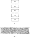
- the figure 3 illustrates the different steps of the process according to the invention, making it possible to construct a porous micromodel intended for the study of flows in a carbonated porous medium.
- the method utilizes an electroplating technique of depositing calcium carbonate on a metal electrode at a negative electric potential.
- An electric potential is one of the magnitudes defining the electrical state of a point of space. His unit is the volt. It may be defined as follows: for any point in an electrical circuit, energy equivalent to the work done to bring a positive charge unit from a zero potential reference point.
- the method consists of applying a mask on the glass plate, and to perform an attack of the glass, protected by the mask.
- the technique involves passing ink (V) through a perforated screen (ES), as illustrated by Figure 5C .
- This ink is deposited on the support by drawing the open forms of the screen.
- This screen (ES) consists of a wooden or aluminum frame, on which is applied a polyester mesh (MP) of different fineness depending on the work to be done.
- the screen is realized ( Figure 5A ) by coating the polyester with a photosensitive gelatin (GP), and then placing on it the mask (F) created in step A. By reacting the gelatin, covered by the positive mask (F), with the ultraviolet (UV) light, it changes and remains permeable only the unexposed parts (that is, those hidden by the printed parts of the mask).
- the ink (V) will only pass through these open parts of the screen.
- the Figure 5B illustrates the result, that is to say the screen screen (ES).
- This process of creating the screen is the preparatory phase of screen printing.
- the manipulator must then position the screen (ES) on the glass plate (support to be printed), then transfer the ink to the support ( Figure 5C ).
- ES screen
- Figure 5C support
- a squeegee he passes the ink on the screen to pass through the openwork parts of the frame.
- the ink is deposited on the support. This action is commonly called a passage.
- This ink (V) deposited by screen printing on the glass plate, is in fact a protective varnish. This varnish masks the parts of the plate that must not be engraved: the inside of the discs is protected.
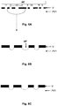
- the Figures 6A to 6C illustrate this step.
- the etching then consists of removing material in the regions not protected by the varnish, so as to engrave a set of intersecting channels forming a network whose nodes constitute pores.
- Wet etching with an acidic aqueous solution can be used. But we can also consider a gas phase attack.
- Hydrofluoric acid strongly and rapidly attacks all silicate surfaces. With some of its compounds, it is the only product capable of chemically attacking the glass in its thickness at a speed sufficient for its action to be practically usable. Hydrofluoric acid (HF molar mass 20.02 g / mol) is sold in expanded form at 40, 48 or 70%. The 40% form, the most common, is the most suitable for engraving on glass.
- etching is done by carefully applying hydrofluoric acid to the glass plate.
- the varnished parts being protected, the attack is made only on the virgin parts (transparent).
- the depth of the engraving varies with the duration of the contact, which is why it is important to control this duration of exposure to the acid, in order to have the hollows around the circles and the veins (bowls) of a depth as homogeneous as possible.
- the attack time is about 3 minutes with 40% acid.
- the desired depth is about 0.3 mm.
- the determination of this optimal attack time required several tests in 30-second increments.
- the etching is called isotropic: the glass is attacked equivalently in all directions of space.
- the plate then comprises a network of channels dimensioned so as to translate physical properties of the porous medium, that is to say that this network of channels has a geometry equivalent to the porous network of the medium, so that the flows are similar in both networks.
- An objective of the process is to construct a porous micromodel representative of porous carbonated media.
- CaCO3 calcium carbonate
- the idea is then to develop a technique to obtain a uniform calcite layer of known thickness in a transparent medium, in order to be able to observe and interpret the microscopic phenomena taking place in carbonate rocks.
- an electroplating technique is used.
- the principle consists in depositing calcium carbonate on a metal electrode brought to a negative electrical potential with respect to a reference electrode.
- the reduction of oxygen to hydroxide ions causes an increase in the pH at the surface of the concentration of carbonate ions, which lead to the formation of calcite.
- This process allows a fast and homogeneous deposition of calcite, and a strong encrustation of the crystal on the metal, due to the crossing of the Coulomb repulsion, and to the Van der Walls interactions.
- the thickness of the deposit is controlled by the intensity of the current. This decreases during scaling due to the limitations of ion diffusion through the deposited layer. Also, there is a clear decrease in the speed of the process after a thickness of a few micrometers. The time to obtain this critical thickness depends on the scaling power of the water but is of the order of only a few minutes. It is nevertheless possible to continue after this time of scaling to slightly increase the deposit with the aid of the residual current.
- the etching of the network generally consists of a hydrofluoric acid wet etching process. This acid attacks minerals but not metals.
- the closure of the micromodel with the upper glass plate by thermo welding at 635 ° C would be compromised. To properly stick, no impurity should be placed between the softened glasses, under penalty of losing the seal and the mechanical strength of the assembly.
- the surface treatment is therefore delicate, and requires post-treatment: the metal coating must be deposited after etching the glass plate, only inside the porous network, and not on the surface of the the glass plate.
- a thin metal deposit (M) is made on the already engraved glass plate, and on which the varnish is still in place. The metal is then deposited on the varnish and the bottom of the holes ( Fig. 7A ).
- the metal deposit can be made with indium tin oxide (or indium oxide doped with tin or ITO for the English name: Indium tin oxide). It is a mixture of indium (III) oxide (In2O3) and tin oxide (IV) (SnO2), in the typical mass proportion of 90% of the first and 10% of the second.
- ITO indium tin oxide
- the main characteristic of indium-tin oxide is its combination of electrical conductivity and optical transparency.
- the thin ITO layers are most often deposited on surfaces by electron beam evaporation, vapor phase physical deposition or other vapor deposition techniques.
- the precipitation reaction follows two different laws depending on the pH. At a pH below 10.3 at 25 ° C, the main reaction is as follows: Ca 2+ + 2 HCO 3 - ⁇ CaCO 3 + H 2 O + CO 2
- reaction For a higher pH, the reaction can be modeled by:
- the electroplating technique requires a potentially calcifying solution, ie rich in calcium ions and carbonate species (H 2 CO 3 , HCO 3 - , CO 3 2- ), in which the engraved glass plate is immersed.
- a potentially calcifying solution ie rich in calcium ions and carbonate species (H 2 CO 3 , HCO 3 - , CO 3 2- )
- TH ° F
- the electrically conductive coating is brought to a negative electric potential, so as to deposit calcium carbonate in the channels.
- the electrically conductive coating which acts as an electrode in the context of electroplating, at a negative electric potential of -1.2V relative to a reference electrode.
- the value chosen corresponds to the redox potential of the pair (02, OH-).
- the reduction of oxygen to hydroxide ions results in an increase in the pH at the surface and an increase in the concentration of carbonate ions, which leads to the formation of calcite.
- the gluing of the plates can then be done by thermo welding, in an oven whose temperature is raised to 635 ° C.
- the engraved plate is placed on a support made of refractory material; the surface of this material has been previously polished (smoothed) to avoid any trace on the glass plate, then, the network is closed by the pierced plate.
- the positioning of the two plates must be precise.
- Two refractory bricks are positioned on the assembly to keep the surfaces to stick well superimposed and to facilitate the bonding.
- the temperature rise is 5 degrees per minute up to 635 ° C. After one hour at this temperature, the heating is stopped. The temperature then drops very slowly in the oven that can be reopened as soon as the temperature reaches about 50 ° C. With heat, the glass softens slightly, without deformation, the plates are soldered. After gradual cooling, the lateral tightness of the micromodels is ensured.
- the process according to the invention is rapid and easily reproducible. It gives a layer of calcite of very good quality by its homogeneity and its regular thickness.
- the adhesion of the crystals is optimal: only a brushing provides the energy necessary for their tearing.
- the second glass plate constitutes a means for sealing the network of channels forming a porous space.
- this means is a transparent glass plate, so as to better visualize the movements of fluids within the network. But we can use other materials ensuring such a seal.
- the second plate can be covered with a calcite deposit, so as to obtain a porous network completely covered with calcite.
- a micromodel whose pores are covered with calcite, makes it possible to study in the laboratory the displacements of multiphase fluids in porous carbonated medium, such as an underground reservoir.
- the canal network must of course be constructed to be representative of the porous network of the underground reservoir.
- the micromodel is placed in a system adapted to apply a desired temperature and pressure.
- This makes it possible to be representative of the thermodynamic conditions of the porous medium studied. Indeed, in the context of an oil reservoir for example, the pressures and the temperatures are high, to the point of influencing considerably the displacements of fluids (modifications of viscosity, phase change, physicochemical reactions, ...) .
- a multiphase fluid is injected into the channel network of the micromodel, and the movement of the fluid, by transparency, through the transparent glass plates is studied.
- the fluids are injected into the micromodel and then recovered at the output before passing through a pressure regulator, which imposes the output pressure at a predetermined value.
- the injection line is thermostatically controlled by means of a heating resistor to maintain the thermodynamic conditions until the entry of the porous medium.
- the micromodel is made of glass and therefore can not withstand a high pressure differential between the inside and the outside. It is therefore contained in a cell of containment which maintains it under an external pressure of nitrogen.
- the overpressure with respect to the pore pressure is about 2 bar.
- the containment cell containing the micromodel is designed to work up to 200 bar. It is equipped with an integrated heating system (with heating candles) allowing experiments beyond 60 ° C. For clarity, two sapphire portholes, one above and one below the micromodel, provide illumination and visualization.
Landscapes
- General Physics & Mathematics (AREA)
- Physics & Mathematics (AREA)
- Engineering & Computer Science (AREA)
- Algebra (AREA)
- Mathematical Analysis (AREA)
- Biochemistry (AREA)
- General Health & Medical Sciences (AREA)
- Chemical & Material Sciences (AREA)
- Immunology (AREA)
- Pathology (AREA)
- Life Sciences & Earth Sciences (AREA)
- Computational Mathematics (AREA)
- Analytical Chemistry (AREA)
- Mathematical Optimization (AREA)
- Mathematical Physics (AREA)
- Pure & Applied Mathematics (AREA)
- Business, Economics & Management (AREA)
- Health & Medical Sciences (AREA)
- Educational Administration (AREA)
- Educational Technology (AREA)
- Theoretical Computer Science (AREA)
- Surface Treatment Of Glass (AREA)
Claims (10)
- Vorrichtung für die Untersuchung der Bewegung von Fluiden in porösem Karbonatmedium, umfassend mindestens eine Glasplatte (PV1), auf der eine Kanalanordnung (R) eingraviert ist, die ein Netz bildet, dadurch gekennzeichnet, dass die Kanäle eine Kalziumkarbonatablagerung umfassen.
- Vorrichtung nach Anspruch 1, wobei das Kanalnetz (R) eine bestimmte Geometrie aufweist, um ähnliche Strömungen in dem Netz (R) und dem Medium zu ermöglichen.
- Vorrichtung nach einem der vorhergehenden Ansprüche, dadurch gekennzeichnet, dass sie ein Mittel zum dichten Schließen des Netzes (R) umfasst.
- Vorrichtung nach einem der vorhergehenden Ansprüche, wobei das Mittel zum dichten Schließen einen Kalzitüberzug umfasst.
- Vorrichtung nach einem der Ansprüche 3 und 4, wobei das Mittel zum dichten Schließen eine zweite Glasplatte (PV2) ist, die auf der gravierten Seite der Glasplatte (PV1) befestigt wird, um das Netz (R) zu schließen.
- Vorrichtung nach Anspruch 5, wobei die zweite Glasplatte (PV2) eine erste Öffnung (EF) an einem Ende und eine zweite Öffnung {SF) an einem anderen Ende umfasst, wobei die Öffnungen derart angebracht sind, dass durch eine der Öffnungen Fluide durch das Kanalnetz injiziert werden können, und derart, dass aus der Vorrichtung durch die zweite Öffnung die Fluide, die durch das Netz (R) zirkulierten, extrahiert werden können.
- Verfahren zur Herstellung einer Vorrichtung zum Untersuchen der Bewegung von Fluiden in porösem Karbonatmedium, wobei auf eine Seite einer transparenten Glasplatte eine Anordnung von Kanälen, die ein Netz bilden (GRAV), graviert wird, dadurch gekennzeichnet, dass das Verfahren die folgenden Schritte umfasst:- Abscheiden eines elektrisch leitenden Überzugs im Innern der Kanäle (DEPM);- Eintauchen der ersten Glasplatte in eine kalkbildende Lösung (PSC); und- Anlegen eines elektrischen Potenzials an den elektrisch leitenden Überzug, um durch elektrisches Abscheiden (PN) eine Kalziumkarbonatablagerung in den Kanälen durchzuführen.
- Verfahren nach Anspruch 7, wobei es sich bei dem elektrisch leitenden Überzug um einen Metallüberzug (M) handelt.
- Verfahren nach einem der Ansprüche 7 und 8, wobei das Netz auf dichte Weise geschlossen wird, indem ein Verschlussmittel, wie beispielsweise eine zweite Glasplatte (PV2), auf der gravierten Seite der Glasplatte (PV1) befestigt wird.
- Verfahren zum Untersuchen im Labor der Bewegung von Fluiden in porösem Karbonatmedium, wie beispielsweise einer unterirdischen Lagerstätte, wobei:- die Vorrichtung nach einem der Ansprüche 1 bis 6 in einem System angeordnet wird, das geeignet ist, ausgewählte thermodynamische Bedingungen anzuwenden,- mindestens ein Fluid in das Kanalnetz injiziert wird, und- die Bewegung der Fluide durch die Glasplatte beobachtet wird.
Applications Claiming Priority (1)
| Application Number | Priority Date | Filing Date | Title |
|---|---|---|---|
| FR0801191A FR2928484B1 (fr) | 2008-03-04 | 2008-03-04 | Dispositif representatif d'un reseau poreux carbonate et procede de fabrication |
Publications (2)
| Publication Number | Publication Date |
|---|---|
| EP2104082A1 EP2104082A1 (de) | 2009-09-23 |
| EP2104082B1 true EP2104082B1 (de) | 2017-06-28 |
Family
ID=40091330
Family Applications (1)
| Application Number | Title | Priority Date | Filing Date |
|---|---|---|---|
| EP09290136.2A Not-in-force EP2104082B1 (de) | 2008-03-04 | 2009-02-26 | Repräsentative Vorrichtung eines porösen Karbonatnetzes und Herstellungsverfahren |
Country Status (2)
| Country | Link |
|---|---|
| EP (1) | EP2104082B1 (de) |
| FR (1) | FR2928484B1 (de) |
Cited By (1)
| Publication number | Priority date | Publication date | Assignee | Title |
|---|---|---|---|---|
| US12226774B2 (en) | 2020-09-29 | 2025-02-18 | Saudi Arabian Oil Company | Microfluidic device and direct measurement of reaction rate |
Families Citing this family (14)
| Publication number | Priority date | Publication date | Assignee | Title |
|---|---|---|---|---|
| CN102839968B (zh) * | 2012-09-13 | 2015-09-16 | 中国石油大学(北京) | 高压注气驱油全程可视实验装置和方法 |
| CN103345864A (zh) * | 2013-07-23 | 2013-10-09 | 湖州文思必得科教仪器有限公司 | 绳波演示器 |
| CN108564866B (zh) * | 2018-01-26 | 2024-05-10 | 中国地质大学(武汉) | 一种油气运移与成藏过程的模拟实验装置 |
| CA3133682A1 (en) | 2019-03-15 | 2020-09-24 | Saudi Arabian Oil Company | Bulk synthesis of janus nanomaterials |
| WO2021011755A1 (en) | 2019-07-16 | 2021-01-21 | Saudi Arabian Oil Company | Multipurpose microfluidics devices for rapid on-site optical chemical analysis |
| US11422285B2 (en) | 2020-06-17 | 2022-08-23 | Saudi Arabian Oil Company | Nanofluidic chips as micromodels for carbonate reservoirs |
| US11773715B2 (en) | 2020-09-03 | 2023-10-03 | Saudi Arabian Oil Company | Injecting multiple tracer tag fluids into a wellbore |
| US11610509B2 (en) | 2021-01-04 | 2023-03-21 | Saudi Arabian Oil Company | Fabrication of micromodels for carbonate reservoirs |
| US11660595B2 (en) | 2021-01-04 | 2023-05-30 | Saudi Arabian Oil Company | Microfluidic chip with multiple porosity regions for reservoir modeling |
| CN112927592A (zh) * | 2021-01-14 | 2021-06-08 | 中国石油天然气股份有限公司 | 一种可视化不同缝网形态的仿真物理模型及制作方法 |
| US11534759B2 (en) | 2021-01-22 | 2022-12-27 | Saudi Arabian Oil Company | Microfluidic chip with mixed porosities for reservoir modeling |
| CN114166719B (zh) * | 2021-11-27 | 2022-08-12 | 北京擎科生物科技有限公司 | 核酸合成载体筛选方法与装置 |
| US12253467B2 (en) | 2021-12-13 | 2025-03-18 | Saudi Arabian Oil Company | Determining partition coefficients of tracer analytes |
| US12000278B2 (en) | 2021-12-16 | 2024-06-04 | Saudi Arabian Oil Company | Determining oil and water production rates in multiple production zones from a single production well |
Family Cites Families (3)
| Publication number | Priority date | Publication date | Assignee | Title |
|---|---|---|---|---|
| US4882763A (en) * | 1984-12-31 | 1989-11-21 | The Standard Oil Company | Method of making a rock-pore micromodel involving generation of an accurate and reliable template image of an actual reservoir rock pore system |
| CA1250644A (en) | 1984-12-31 | 1989-02-28 | Robert Ehrlich | Method of making rock-pore micromodel involving generation of an accurate and reliable template image of an actual reservoir rock pore system |
| FR2756046B1 (fr) | 1996-11-18 | 1998-12-24 | Inst Francais Du Petrole | Methode pour modeliser la distribution des pores d'un echantillon poreux de porosite variable |
-
2008
- 2008-03-04 FR FR0801191A patent/FR2928484B1/fr active Active
-
2009
- 2009-02-26 EP EP09290136.2A patent/EP2104082B1/de not_active Not-in-force
Non-Patent Citations (1)
| Title |
|---|
| None * |
Cited By (1)
| Publication number | Priority date | Publication date | Assignee | Title |
|---|---|---|---|---|
| US12226774B2 (en) | 2020-09-29 | 2025-02-18 | Saudi Arabian Oil Company | Microfluidic device and direct measurement of reaction rate |
Also Published As
| Publication number | Publication date |
|---|---|
| FR2928484A1 (fr) | 2009-09-11 |
| FR2928484B1 (fr) | 2010-12-17 |
| EP2104082A1 (de) | 2009-09-23 |
Similar Documents
| Publication | Publication Date | Title |
|---|---|---|
| EP2104082B1 (de) | Repräsentative Vorrichtung eines porösen Karbonatnetzes und Herstellungsverfahren | |
| Meng et al. | High‐Resolution Erasable “Live” Patterns Based on Controllable Ink Diffusion on the 3D Blue‐Phase Liquid Crystal Networks | |
| Farhadi et al. | Experimental investigation on the dominating fluid-fluid and rock-fluid interactions during low salinity water flooding in water-wet and oil-wet calcites | |
| Zaeri et al. | Enhanced oil recovery from carbonate reservoirs by spontaneous imbibition of low salinity water | |
| Sato et al. | Structural color films with lotus effects, superhydrophilicity, and tunable stop-bands | |
| Karadimitriou et al. | A review of micromodels and their use in two-phase flow studies | |
| Singh et al. | Real rock-microfluidic flow cell: A test bed for real-time in situ analysis of flow, transport, and reaction in a subsurface reactive transport environment | |
| CN101392641B (zh) | 一种实时观察真实岩心原油驱替过程的方法 | |
| EP2699353A1 (de) | Mikrofluidisches system zur regelung der konzentration von molekülen zur stimulierung eines ziels | |
| FR2798697A1 (fr) | Procede pour reduire la permeabilite relative a l'eau dans des formations petroliferes | |
| Chalbaud et al. | Wettability impact on CO2 storage in aquifers: visualisation and quantification using micromodel tests, pore network model and reservoir simulations | |
| Liu et al. | Nanoimprinted ultrafine line and space nanogratings for liquid crystal alignment | |
| AlOmier et al. | Experimental investigation of the impact of mixed wettability on pore-scale fluid displacement: A microfluidic study | |
| Javadpour et al. | Nanotechnology-based micromodels and new image analysis to study transport in porous media | |
| Rao et al. | Mineral interfaces and oil recovery: a microscopic view on surface reconstruction, organic modification, and wettability alteration of carbonates | |
| US11660595B2 (en) | Microfluidic chip with multiple porosity regions for reservoir modeling | |
| Shoukry et al. | Pore-scale experimental investigation of capillary desaturation in fractured porous media | |
| Jin et al. | Visually invisible multimode anti-counterfeiting based on highly transparent superamphiphobic/superhydrophilic pattern | |
| Ding et al. | Downward fingering accompanies upward tube growth in a chemical garden grown in a vertical confined geometry | |
| Fadili et al. | Injectivity decline by nanoparticles transport in high permeable rock | |
| Gao et al. | Combined microfluidics–confocal Raman microscopy platform for studying enhanced oil recovery mechanisms | |
| Zhang et al. | Pore-scale mechanisms of salt precipitation in heterogeneous media under geological carbon storage conditions | |
| Gouet-Kaplan et al. | Measurements of interactions between resident and infiltrating water in a lattice micromodel | |
| Jamaloei et al. | Effect of monovalent and divalent ions on macroscopic behaviour of surfactant flooding | |
| Omran et al. | Screening of nanoparticles with considering the pore structure and initial oil connectivity effects |
Legal Events
| Date | Code | Title | Description |
|---|---|---|---|
| PUAI | Public reference made under article 153(3) epc to a published international application that has entered the european phase |
Free format text: ORIGINAL CODE: 0009012 |
|
| AK | Designated contracting states |
Kind code of ref document: A1 Designated state(s): AT BE BG CH CY CZ DE DK EE ES FI FR GB GR HR HU IE IS IT LI LT LU LV MC MK MT NL NO PL PT RO SE SI SK TR |
|
| AX | Request for extension of the european patent |
Extension state: AL BA RS |
|
| 17P | Request for examination filed |
Effective date: 20100323 |
|
| 17Q | First examination report despatched |
Effective date: 20100415 |
|
| AKX | Designation fees paid |
Designated state(s): AT BE BG CH CY CZ DE DK EE ES FI FR GB GR HR HU IE IS IT LI LT LU LV MC MK MT NL NO PL PT RO SE SI SK TR |
|
| RAP1 | Party data changed (applicant data changed or rights of an application transferred) |
Owner name: IFP ENERGIES NOUVELLES |
|
| GRAP | Despatch of communication of intention to grant a patent |
Free format text: ORIGINAL CODE: EPIDOSNIGR1 |
|
| INTG | Intention to grant announced |
Effective date: 20170215 |
|
| GRAS | Grant fee paid |
Free format text: ORIGINAL CODE: EPIDOSNIGR3 |
|
| GRAA | (expected) grant |
Free format text: ORIGINAL CODE: 0009210 |
|
| AK | Designated contracting states |
Kind code of ref document: B1 Designated state(s): AT BE BG CH CY CZ DE DK EE ES FI FR GB GR HR HU IE IS IT LI LT LU LV MC MK MT NL NO PL PT RO SE SI SK TR |
|
| REG | Reference to a national code |
Ref country code: GB Ref legal event code: FG4D Free format text: NOT ENGLISH |
|
| REG | Reference to a national code |
Ref country code: CH Ref legal event code: EP |
|
| REG | Reference to a national code |
Ref country code: AT Ref legal event code: REF Ref document number: 905486 Country of ref document: AT Kind code of ref document: T Effective date: 20170715 |
|
| REG | Reference to a national code |
Ref country code: IE Ref legal event code: FG4D Free format text: LANGUAGE OF EP DOCUMENT: FRENCH |
|
| REG | Reference to a national code |
Ref country code: DE Ref legal event code: R096 Ref document number: 602009046835 Country of ref document: DE |
|
| REG | Reference to a national code |
Ref country code: NL Ref legal event code: FP |
|
| PG25 | Lapsed in a contracting state [announced via postgrant information from national office to epo] |
Ref country code: GR Free format text: LAPSE BECAUSE OF FAILURE TO SUBMIT A TRANSLATION OF THE DESCRIPTION OR TO PAY THE FEE WITHIN THE PRESCRIBED TIME-LIMIT Effective date: 20170929 Ref country code: HR Free format text: LAPSE BECAUSE OF FAILURE TO SUBMIT A TRANSLATION OF THE DESCRIPTION OR TO PAY THE FEE WITHIN THE PRESCRIBED TIME-LIMIT Effective date: 20170628 Ref country code: FI Free format text: LAPSE BECAUSE OF FAILURE TO SUBMIT A TRANSLATION OF THE DESCRIPTION OR TO PAY THE FEE WITHIN THE PRESCRIBED TIME-LIMIT Effective date: 20170628 Ref country code: LT Free format text: LAPSE BECAUSE OF FAILURE TO SUBMIT A TRANSLATION OF THE DESCRIPTION OR TO PAY THE FEE WITHIN THE PRESCRIBED TIME-LIMIT Effective date: 20170628 |
|
| RAP2 | Party data changed (patent owner data changed or rights of a patent transferred) |
Owner name: IFP ENERGIES NOUVELLES |
|
| REG | Reference to a national code |
Ref country code: LT Ref legal event code: MG4D |
|
| REG | Reference to a national code |
Ref country code: AT Ref legal event code: MK05 Ref document number: 905486 Country of ref document: AT Kind code of ref document: T Effective date: 20170628 |
|
| PG25 | Lapsed in a contracting state [announced via postgrant information from national office to epo] |
Ref country code: LV Free format text: LAPSE BECAUSE OF FAILURE TO SUBMIT A TRANSLATION OF THE DESCRIPTION OR TO PAY THE FEE WITHIN THE PRESCRIBED TIME-LIMIT Effective date: 20170628 Ref country code: SE Free format text: LAPSE BECAUSE OF FAILURE TO SUBMIT A TRANSLATION OF THE DESCRIPTION OR TO PAY THE FEE WITHIN THE PRESCRIBED TIME-LIMIT Effective date: 20170628 Ref country code: BG Free format text: LAPSE BECAUSE OF FAILURE TO SUBMIT A TRANSLATION OF THE DESCRIPTION OR TO PAY THE FEE WITHIN THE PRESCRIBED TIME-LIMIT Effective date: 20170928 |
|
| REG | Reference to a national code |
Ref country code: NO Ref legal event code: T2 Effective date: 20170628 |
|
| PG25 | Lapsed in a contracting state [announced via postgrant information from national office to epo] |
Ref country code: SK Free format text: LAPSE BECAUSE OF FAILURE TO SUBMIT A TRANSLATION OF THE DESCRIPTION OR TO PAY THE FEE WITHIN THE PRESCRIBED TIME-LIMIT Effective date: 20170628 Ref country code: EE Free format text: LAPSE BECAUSE OF FAILURE TO SUBMIT A TRANSLATION OF THE DESCRIPTION OR TO PAY THE FEE WITHIN THE PRESCRIBED TIME-LIMIT Effective date: 20170628 Ref country code: CZ Free format text: LAPSE BECAUSE OF FAILURE TO SUBMIT A TRANSLATION OF THE DESCRIPTION OR TO PAY THE FEE WITHIN THE PRESCRIBED TIME-LIMIT Effective date: 20170628 Ref country code: AT Free format text: LAPSE BECAUSE OF FAILURE TO SUBMIT A TRANSLATION OF THE DESCRIPTION OR TO PAY THE FEE WITHIN THE PRESCRIBED TIME-LIMIT Effective date: 20170628 Ref country code: RO Free format text: LAPSE BECAUSE OF FAILURE TO SUBMIT A TRANSLATION OF THE DESCRIPTION OR TO PAY THE FEE WITHIN THE PRESCRIBED TIME-LIMIT Effective date: 20170628 |
|
| PG25 | Lapsed in a contracting state [announced via postgrant information from national office to epo] |
Ref country code: ES Free format text: LAPSE BECAUSE OF FAILURE TO SUBMIT A TRANSLATION OF THE DESCRIPTION OR TO PAY THE FEE WITHIN THE PRESCRIBED TIME-LIMIT Effective date: 20170628 Ref country code: IS Free format text: LAPSE BECAUSE OF FAILURE TO SUBMIT A TRANSLATION OF THE DESCRIPTION OR TO PAY THE FEE WITHIN THE PRESCRIBED TIME-LIMIT Effective date: 20171028 Ref country code: PL Free format text: LAPSE BECAUSE OF FAILURE TO SUBMIT A TRANSLATION OF THE DESCRIPTION OR TO PAY THE FEE WITHIN THE PRESCRIBED TIME-LIMIT Effective date: 20170628 Ref country code: IT Free format text: LAPSE BECAUSE OF FAILURE TO SUBMIT A TRANSLATION OF THE DESCRIPTION OR TO PAY THE FEE WITHIN THE PRESCRIBED TIME-LIMIT Effective date: 20170628 |
|
| REG | Reference to a national code |
Ref country code: DE Ref legal event code: R097 Ref document number: 602009046835 Country of ref document: DE |
|
| PG25 | Lapsed in a contracting state [announced via postgrant information from national office to epo] |
Ref country code: DK Free format text: LAPSE BECAUSE OF FAILURE TO SUBMIT A TRANSLATION OF THE DESCRIPTION OR TO PAY THE FEE WITHIN THE PRESCRIBED TIME-LIMIT Effective date: 20170628 |
|
| PLBE | No opposition filed within time limit |
Free format text: ORIGINAL CODE: 0009261 |
|
| STAA | Information on the status of an ep patent application or granted ep patent |
Free format text: STATUS: NO OPPOSITION FILED WITHIN TIME LIMIT |
|
| 26N | No opposition filed |
Effective date: 20180329 |
|
| PG25 | Lapsed in a contracting state [announced via postgrant information from national office to epo] |
Ref country code: SI Free format text: LAPSE BECAUSE OF FAILURE TO SUBMIT A TRANSLATION OF THE DESCRIPTION OR TO PAY THE FEE WITHIN THE PRESCRIBED TIME-LIMIT Effective date: 20170628 |
|
| REG | Reference to a national code |
Ref country code: DE Ref legal event code: R119 Ref document number: 602009046835 Country of ref document: DE |
|
| REG | Reference to a national code |
Ref country code: CH Ref legal event code: PL |
|
| REG | Reference to a national code |
Ref country code: NO Ref legal event code: MMEP |
|
| PG25 | Lapsed in a contracting state [announced via postgrant information from national office to epo] |
Ref country code: MC Free format text: LAPSE BECAUSE OF FAILURE TO SUBMIT A TRANSLATION OF THE DESCRIPTION OR TO PAY THE FEE WITHIN THE PRESCRIBED TIME-LIMIT Effective date: 20170628 Ref country code: MT Free format text: LAPSE BECAUSE OF FAILURE TO SUBMIT A TRANSLATION OF THE DESCRIPTION OR TO PAY THE FEE WITHIN THE PRESCRIBED TIME-LIMIT Effective date: 20170628 |
|
| REG | Reference to a national code |
Ref country code: NL Ref legal event code: MM Effective date: 20180301 |
|
| GBPC | Gb: european patent ceased through non-payment of renewal fee |
Effective date: 20180226 |
|
| PG25 | Lapsed in a contracting state [announced via postgrant information from national office to epo] |
Ref country code: NO Free format text: LAPSE BECAUSE OF NON-PAYMENT OF DUE FEES Effective date: 20180228 |
|
| REG | Reference to a national code |
Ref country code: IE Ref legal event code: MM4A |
|
| REG | Reference to a national code |
Ref country code: BE Ref legal event code: MM Effective date: 20180228 |
|
| PG25 | Lapsed in a contracting state [announced via postgrant information from national office to epo] |
Ref country code: LU Free format text: LAPSE BECAUSE OF NON-PAYMENT OF DUE FEES Effective date: 20180226 Ref country code: LI Free format text: LAPSE BECAUSE OF NON-PAYMENT OF DUE FEES Effective date: 20180228 Ref country code: CH Free format text: LAPSE BECAUSE OF NON-PAYMENT OF DUE FEES Effective date: 20180228 |
|
| REG | Reference to a national code |
Ref country code: FR Ref legal event code: ST Effective date: 20181031 |
|
| PG25 | Lapsed in a contracting state [announced via postgrant information from national office to epo] |
Ref country code: NL Free format text: LAPSE BECAUSE OF NON-PAYMENT OF DUE FEES Effective date: 20180301 |
|
| PG25 | Lapsed in a contracting state [announced via postgrant information from national office to epo] |
Ref country code: IE Free format text: LAPSE BECAUSE OF NON-PAYMENT OF DUE FEES Effective date: 20180226 Ref country code: DE Free format text: LAPSE BECAUSE OF NON-PAYMENT OF DUE FEES Effective date: 20180901 |
|
| PG25 | Lapsed in a contracting state [announced via postgrant information from national office to epo] |
Ref country code: GB Free format text: LAPSE BECAUSE OF NON-PAYMENT OF DUE FEES Effective date: 20180226 Ref country code: BE Free format text: LAPSE BECAUSE OF NON-PAYMENT OF DUE FEES Effective date: 20180228 Ref country code: FR Free format text: LAPSE BECAUSE OF NON-PAYMENT OF DUE FEES Effective date: 20180228 |
|
| PG25 | Lapsed in a contracting state [announced via postgrant information from national office to epo] |
Ref country code: TR Free format text: LAPSE BECAUSE OF FAILURE TO SUBMIT A TRANSLATION OF THE DESCRIPTION OR TO PAY THE FEE WITHIN THE PRESCRIBED TIME-LIMIT Effective date: 20170628 |
|
| PG25 | Lapsed in a contracting state [announced via postgrant information from national office to epo] |
Ref country code: HU Free format text: LAPSE BECAUSE OF FAILURE TO SUBMIT A TRANSLATION OF THE DESCRIPTION OR TO PAY THE FEE WITHIN THE PRESCRIBED TIME-LIMIT; INVALID AB INITIO Effective date: 20090226 Ref country code: PT Free format text: LAPSE BECAUSE OF FAILURE TO SUBMIT A TRANSLATION OF THE DESCRIPTION OR TO PAY THE FEE WITHIN THE PRESCRIBED TIME-LIMIT Effective date: 20170628 |
|
| PG25 | Lapsed in a contracting state [announced via postgrant information from national office to epo] |
Ref country code: CY Free format text: LAPSE BECAUSE OF FAILURE TO SUBMIT A TRANSLATION OF THE DESCRIPTION OR TO PAY THE FEE WITHIN THE PRESCRIBED TIME-LIMIT Effective date: 20170628 Ref country code: MK Free format text: LAPSE BECAUSE OF NON-PAYMENT OF DUE FEES Effective date: 20170628 |