EP2104016B1 - Electric heating device comprising an infrared sensor - Google Patents
Electric heating device comprising an infrared sensor Download PDFInfo
- Publication number
- EP2104016B1 EP2104016B1 EP09305076A EP09305076A EP2104016B1 EP 2104016 B1 EP2104016 B1 EP 2104016B1 EP 09305076 A EP09305076 A EP 09305076A EP 09305076 A EP09305076 A EP 09305076A EP 2104016 B1 EP2104016 B1 EP 2104016B1
- Authority
- EP
- European Patent Office
- Prior art keywords
- temperature
- electric heating
- fact
- infrared sensor
- heating appliance
- Prior art date
- Legal status (The legal status is an assumption and is not a legal conclusion. Google has not performed a legal analysis and makes no representation as to the accuracy of the status listed.)
- Not-in-force
Links
- 238000005485 electric heating Methods 0.000 title claims description 13
- 238000010438 heat treatment Methods 0.000 claims description 12
- 230000005855 radiation Effects 0.000 claims description 4
- 239000003570 air Substances 0.000 description 5
- 239000000523 sample Substances 0.000 description 5
- 238000004519 manufacturing process Methods 0.000 description 2
- 241000276498 Pollachius virens Species 0.000 description 1
- 239000012080 ambient air Substances 0.000 description 1
- 230000003321 amplification Effects 0.000 description 1
- 238000009529 body temperature measurement Methods 0.000 description 1
- 239000003990 capacitor Substances 0.000 description 1
- 238000004891 communication Methods 0.000 description 1
- 238000005516 engineering process Methods 0.000 description 1
- 238000009434 installation Methods 0.000 description 1
- 230000010354 integration Effects 0.000 description 1
- 238000003199 nucleic acid amplification method Methods 0.000 description 1
- 230000001681 protective effect Effects 0.000 description 1
- 238000000926 separation method Methods 0.000 description 1
Images
Classifications
-
- G—PHYSICS
- G05—CONTROLLING; REGULATING
- G05D—SYSTEMS FOR CONTROLLING OR REGULATING NON-ELECTRIC VARIABLES
- G05D23/00—Control of temperature
- G05D23/19—Control of temperature characterised by the use of electric means
- G05D23/27—Control of temperature characterised by the use of electric means with sensing element responsive to radiation
-
- F—MECHANICAL ENGINEERING; LIGHTING; HEATING; WEAPONS; BLASTING
- F24—HEATING; RANGES; VENTILATING
- F24H—FLUID HEATERS, e.g. WATER OR AIR HEATERS, HAVING HEAT-GENERATING MEANS, e.g. HEAT PUMPS, IN GENERAL
- F24H15/00—Control of fluid heaters
- F24H15/10—Control of fluid heaters characterised by the purpose of the control
- F24H15/176—Improving or maintaining comfort of users
-
- F—MECHANICAL ENGINEERING; LIGHTING; HEATING; WEAPONS; BLASTING
- F24—HEATING; RANGES; VENTILATING
- F24H—FLUID HEATERS, e.g. WATER OR AIR HEATERS, HAVING HEAT-GENERATING MEANS, e.g. HEAT PUMPS, IN GENERAL
- F24H15/00—Control of fluid heaters
- F24H15/20—Control of fluid heaters characterised by control inputs
- F24H15/254—Room temperature
-
- F—MECHANICAL ENGINEERING; LIGHTING; HEATING; WEAPONS; BLASTING
- F24—HEATING; RANGES; VENTILATING
- F24H—FLUID HEATERS, e.g. WATER OR AIR HEATERS, HAVING HEAT-GENERATING MEANS, e.g. HEAT PUMPS, IN GENERAL
- F24H15/00—Control of fluid heaters
- F24H15/30—Control of fluid heaters characterised by control outputs; characterised by the components to be controlled
- F24H15/355—Control of heat-generating means in heaters
- F24H15/37—Control of heat-generating means in heaters of electric heaters
-
- F—MECHANICAL ENGINEERING; LIGHTING; HEATING; WEAPONS; BLASTING
- F24—HEATING; RANGES; VENTILATING
- F24H—FLUID HEATERS, e.g. WATER OR AIR HEATERS, HAVING HEAT-GENERATING MEANS, e.g. HEAT PUMPS, IN GENERAL
- F24H15/00—Control of fluid heaters
- F24H15/40—Control of fluid heaters characterised by the type of controllers
- F24H15/414—Control of fluid heaters characterised by the type of controllers using electronic processing, e.g. computer-based
-
- F—MECHANICAL ENGINEERING; LIGHTING; HEATING; WEAPONS; BLASTING
- F24—HEATING; RANGES; VENTILATING
- F24H—FLUID HEATERS, e.g. WATER OR AIR HEATERS, HAVING HEAT-GENERATING MEANS, e.g. HEAT PUMPS, IN GENERAL
- F24H9/00—Details
- F24H9/20—Arrangement or mounting of control or safety devices
- F24H9/2064—Arrangement or mounting of control or safety devices for air heaters
- F24H9/2071—Arrangement or mounting of control or safety devices for air heaters using electrical energy supply
-
- F—MECHANICAL ENGINEERING; LIGHTING; HEATING; WEAPONS; BLASTING
- F24—HEATING; RANGES; VENTILATING
- F24H—FLUID HEATERS, e.g. WATER OR AIR HEATERS, HAVING HEAT-GENERATING MEANS, e.g. HEAT PUMPS, IN GENERAL
- F24H15/00—Control of fluid heaters
- F24H15/30—Control of fluid heaters characterised by control outputs; characterised by the components to be controlled
- F24H15/395—Information to users, e.g. alarms
Definitions
- the invention relates to an electric heater comprising at least one heating element, of the type comprising a housing carrying control and regulation members connected to an electronic card receiving a signal representative of a temperature transmitted by a corresponding sensor.
- control thermostat For heating homes, offices or other inhabited premises, electric heaters are used with a control thermostat connected to a sensor measuring an air temperature. This sensor is usually placed at the bottom of the electric heater, and thus measures the ambient air temperature at ground level before it is heated by the heating element of the electric heater.
- the control thermostat has a control box with control and control elements, such as the on / off switch, temperature control knob, operating mode switch, etc. This control unit is ergonomically placed in the upper part, at the top of the electric heater.
- the bottom temperature probe sensor must be connected to the control box in the upper part by a communication means consisting of a double insulated electrical cable, called "probe cable”.
- the sensor or temperature sensor must also, in practice, be protected by a small housing or internal separation to the electric heater.
- the air temperature measured by the sensor or temperature sensor is not representative of the thermal environment of the heated room; on the other hand, the requirement of a connection "probe cable” and a small protective housing of the probe or temperature sensor increases the manufacturing and complicates the installation of an electric heater.
- the document DE 4135086 (INTERCONTROL KOEHLER HERMANN) describes a thermostat-free wall-mounted thermostat housing with an infrared temperature sensor aimed at a nearby intermediate target, to reduce noise that easily disrupts the sensor's low-level signals.
- a first object of the invention is to improve the regulation of an electric heater, by measuring an average ambient temperature representative of the ambient comfort.
- a second object of the invention is to allow a direct connection between the temperature sensor and the control box, by eliminating the probe cable connecting the control box to the temperature sensor.
- a third object of the invention is to provide a thermostat by integration on an electronic card, so as to achieve an economic manufacture and assembly of a device according to the invention.
- a fourth object of the invention is to measure an average physical value representative of the air temperature, but also the temperature radiated by a target wall of the dwelling such as wall or ceiling, so as to integrate the concept cold wall radiance.
- the subject of the invention is an electric heating apparatus comprising at least one heating element, of the type comprising a housing carrying control and regulation elements connected to an electronic card receiving a signal representative of a temperature transmitted by a corresponding sensor, characterized by the fact that the temperature sensor is an infrared sensor mounted directly on the electronic board of the apparatus and oriented towards a window or opening of capture of the ambient infrared radiation, made in the housing, to enable the infrared temperature sensor to measure an average ambient temperature representative of the ambient comfort and the fact that the infrared radiation capture opening is oriented towards a wall or an extensive surface.
- the electric heater comprising at least one heating element according to the invention is advantageously of the type whose operation is controlled by a thermostat.
- this thermostat is mounted in the upper upper part of the heater.
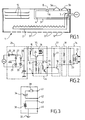
- an electric heating apparatus 1 comprises at least one heating element 2 adapted to be powered by the mains power supply and a device according to the invention forming a regulation thermostat.
- the device according to the invention comprises a housing 3 containing an electronic card 4 including all the means of comparison, amplification, and programming or calculation for the regulation of electric heating.
- the electronic card 4 can in particular carry a temperature control means 5a, an operating mode switching means 5b and a means 7 for switching the power supply of the heating element 2.
- the electronic card 4 carries an infrared sensor 6 mounted and assembled directly to the electronic card 4.
- the infrared sensor 6 is oriented towards a window or opening 8 made in the housing 3, to measure the average ambient temperature representative of the ambient comfort.
- the window 8 is preferably oriented towards a wall such as a wall or other extended surface making it possible to obtain a stable average of the temperature measurements.
- the electrical apparatus comprises, in the lower part, openings 9 for admitting cold air to be heated, and fins 10 for diffusing heated air towards the top and towards the front of the electric heater. according to the invention.
- a simple and economical embodiment of the device according to the invention comprises an electronic circuit built around an infrared temperature sensor 6 with four outputs.
- the electronic circuit is designed to perform an output function "all or nothing with hysteresis", to perform a simple and economical temperature control.
- the sensor 6 comprises a first terminal 11 connected to ground, a second output 12 connected to the block 35 composed of the elements 15,16,24 to provide a stabilized power supply available on a third terminal 13 and a fourth output 14 connected to a resistor 17 and a transistor 18 for driving an indication block 19 and the control block 34 of the heating element.
- the indication block 19 comprises a light-emitting diode 20 and a resistor 22.
- the control unit 34 consists of a diode 23 and a relay 21 of electrical power, to supply or not the heating element 2 of the electric heating apparatus according to the invention.
- a block 33 comprising the resistor 17 and the transistor 18 serves to amplify between the sensor 6 and the indication output 19 and control 33 blocks.
- the circuit 26 transforms the AC voltage into a DC voltage. It comprises a bridge consisting of two diodes 27 and 28 and two Zener diodes 29 and 30, a resistor 31 and a capacitor 32.
- an infrared temperature sensor for a device according to the invention is produced in the form of an integrated circuit, comprising a photocell 38 and a resistor 39 connected in series on a circuit connecting the connection terminals 41 and 42 and comprising a PTC thermistor 36 (with positive temperature coefficient) on a circuit connecting the connection terminal 43 to the connection terminal 44 connected to ground 37.
- the infrared temperature sensors for a device according to the invention can also act as programmable components to several output functions, including the output function "all or nothing with hysteresis" described with reference to the figure 2 .
- an infrared temperature sensor for a device comprises a "target and target temperature serial bus” output function, as well as a PWM output function of "targeted and ambient temperature pulse width modulation” , these functions allowing cooperation with a microcontroller not shown on the electronic card, to perform programming of the temperature control.
- control thermostat forms a complete assembly integrating the temperature sensor and can be mounted in any desired position of the electric heater, preferably in the up position, but also laterally, or possibly in the low position. .
Description
L'invention est relative à un appareil de chauffage électrique comportant au moins un élément chauffant, du type comportant un boîtier portant des organes de commande et de régulation reliées à une carte électronique recevant un signal représentatif d'une température transmis par un capteur correspondant.The invention relates to an electric heater comprising at least one heating element, of the type comprising a housing carrying control and regulation members connected to an electronic card receiving a signal representative of a temperature transmitted by a corresponding sensor.
Pour le chauffage des logements, bureaux ou autres locaux habités, on utilise des appareils de chauffage électrique comportant un thermostat de régulation relié à un capteur mesurant une température d'air. Ce capteur est habituellement placé en partie basse de l'appareil de chauffage électrique, et mesure de ce fait la température de l'air ambiant au niveau du sol avant son réchauffement par l'élément chauffant de l'appareil de chauffage électrique. Le thermostat de régulation comporte un boîtier de commande portant des organes de régulation et de commande, du genre interrupteur marche/arrêt, molette de réglage de température, commutateur de modes de fonctionnement... Ce boîtier de commande est placé, de manière ergonomique, dans la partie supérieure, en haut de l'appareil de chauffage électrique.For heating homes, offices or other inhabited premises, electric heaters are used with a control thermostat connected to a sensor measuring an air temperature. This sensor is usually placed at the bottom of the electric heater, and thus measures the ambient air temperature at ground level before it is heated by the heating element of the electric heater. The control thermostat has a control box with control and control elements, such as the on / off switch, temperature control knob, operating mode switch, etc. This control unit is ergonomically placed in the upper part, at the top of the electric heater.
Dans ce cas, le capteur de sonde de température en partie basse doit être relié au boîtier de commande en partie haute par un moyen de communication constitué par un câble électrique à double isolation, appelé "câble de sonde".In this case, the bottom temperature probe sensor must be connected to the control box in the upper part by a communication means consisting of a double insulated electrical cable, called "probe cable".
Le capteur ou sonde de température doit également, en pratique, être protégé par un petit boîtier ou une séparation interne à l'appareil de chauffage électrique.The sensor or temperature sensor must also, in practice, be protected by a small housing or internal separation to the electric heater.
Cependant, cette technologie connue présente plusieurs inconvénients : d'une part, la température d'air mesurée par le capteur ou sonde de température n'est pas représentative de l'ambiance thermique du local chauffé ; d'autre part, l'exigence d'une liaison par "câble de sonde" et d'un petit boîtier de protection de la sonde ou capteur de température renchérit la fabrication et complique le montage d'un appareil de chauffage électrique.However, this known technology has several disadvantages: firstly, the air temperature measured by the sensor or temperature sensor is not representative of the thermal environment of the heated room; on the other hand, the requirement of a connection "probe cable" and a small protective housing of the probe or temperature sensor increases the manufacturing and complicates the installation of an electric heater.
Le document
Un premier but de l'invention est d'améliorer la régulation d'un appareil de chauffage électrique, en mesurant une température ambiante moyenne représentative du confort ambiant.A first object of the invention is to improve the regulation of an electric heater, by measuring an average ambient temperature representative of the ambient comfort.
Un deuxième but de l'invention est de permettre une liaison directe entre capteur de température et boîtier de commande, en éliminant le câble de sonde reliant le boîtier de commande au capteur de température.A second object of the invention is to allow a direct connection between the temperature sensor and the control box, by eliminating the probe cable connecting the control box to the temperature sensor.
Un troisième but de l'invention est de réaliser un thermostat par intégration sur une carte électronique, de manière à réaliser une fabrication et un montage économiques d'un dispositif selon l'invention.A third object of the invention is to provide a thermostat by integration on an electronic card, so as to achieve an economic manufacture and assembly of a device according to the invention.
Un quatrième but de l'invention est de mesurer une valeur physique moyenne représentative de la température de l'air, mais aussi de la température rayonnée par une paroi visée de l'habitation telle que mur ou plafond, de manière à intégrer ainsi la notion de radiance de paroi froide.A fourth object of the invention is to measure an average physical value representative of the air temperature, but also the temperature radiated by a target wall of the dwelling such as wall or ceiling, so as to integrate the concept cold wall radiance.
L'invention a pour objet un appareil de chauffage électrique comportant au moins un élément chauffant, du type comportant un boîtier portant des organes de commande et de régulation reliées à une carte électronique recevant un signal représentatif d'une température transmis par un capteur correspondant, caractérisé par le fait que le capteur de température est un capteur infrarouge monté directement sur la carte électronique de l'appareil et orienté vers une fenêtre ou ouverture de saisie du rayonnement infrarouge ambiant, pratiquée dans le boîtier, pour permettre au capteur infrarouge de température de mesurer une température ambiante moyenne représentative du confort ambiant et par le fait que l'ouverture de saisie du rayonnement infrarouge est orientée en direction d'une paroi ou d'une surface étendue.The subject of the invention is an electric heating apparatus comprising at least one heating element, of the type comprising a housing carrying control and regulation elements connected to an electronic card receiving a signal representative of a temperature transmitted by a corresponding sensor, characterized by the fact that the temperature sensor is an infrared sensor mounted directly on the electronic board of the apparatus and oriented towards a window or opening of capture of the ambient infrared radiation, made in the housing, to enable the infrared temperature sensor to measure an average ambient temperature representative of the ambient comfort and the fact that the infrared radiation capture opening is oriented towards a wall or an extensive surface.
Selon d'autres caractéristiques alternatives de l'invention :
- le capteur infrarouge de température est un composant programmable à plusieurs fonctions de sortie ;
- le capteur infrarouge de température comporte une fonction de sortie "tout ou rien à hystérésis", pour effectuer une régulation de température simple et économique ;
- le capteur infrarouge de température comporte une fonction de sortie PWM des températures visée et ambiante ;
- le capteur infrarouge de température comporte une fonction de sortie «bus série» des températures visée et ambiante" ;
- le capteur de température infrarouge est relié à un microcontrôleur de la carte électronique, pour effectuer une programmation de la régulation de température.
- the infrared temperature sensor is a programmable component with several output functions;
- the infrared temperature sensor has an output function "all or nothing hysteresis" to perform a simple and economical temperature control;
- the infrared temperature sensor has a PWM output function of the target and ambient temperatures;
- the infrared temperature sensor has a "serial bus" output function of the target and ambient temperatures ";
- the infrared temperature sensor is connected to a microcontroller of the electronic card, to perform programming of the temperature control.
L'appareil de chauffage électrique comportant au moins un élément chauffant selon l'invention est avantageusement du type dont la marche est commandée par un thermostat. De préférence, ce thermostat est monté dans la partie supérieure haute de l'appareil de chauffage.The electric heater comprising at least one heating element according to the invention is advantageously of the type whose operation is controlled by a thermostat. Preferably, this thermostat is mounted in the upper upper part of the heater.
L'invention sera mieux comprise grâce à la description qui va suivre donnée à titre d'exemple non limitatif en référence aux dessins annexés dans lesquels :
- La
figure 1 représente schématiquement un appareil de chauffage électrique selon l'invention ; - La
figure 2 représente schématiquement un circuit électronique pour dispositif selon l'invention ; - La
figure 3 représente schématiquement un circuit intégré constituant un capteur de température pour dispositif selon l'invention.
- The
figure 1 schematically represents an electric heater according to the invention; - The
figure 2 schematically represents an electronic circuit for a device according to the invention; - The
figure 3 schematically represents an integrated circuit constituting a device temperature sensor according to the invention.
Sur la
Le dispositif selon l'invention comporte un boîtier 3 contenant une carte électronique 4 regroupant l'ensemble des moyens de comparaison, d'amplification, et de programmation ou de calcul pour la régulation du chauffage électrique.The device according to the invention comprises a
La carte électronique 4 peut notamment porter un moyen 5a de réglage de température, un moyen 5b de commutation de modes de fonctionnement et un moyen 7 de commutation de l'alimentation électrique de l'élément chauffant 2.The electronic card 4 can in particular carry a temperature control means 5a, an operating mode switching means 5b and a means 7 for switching the power supply of the
Selon l'invention, la carte électronique 4 porte un capteur infrarouge 6 monté et assemblé directement à la carte électronique 4.According to the invention, the electronic card 4 carries an infrared sensor 6 mounted and assembled directly to the electronic card 4.
Le capteur infrarouge 6 est orienté en direction d'une fenêtre ou ouverture 8 pratiquée dans le boîtier 3, pour permettre de mesurer la température ambiante moyenne représentative du confort ambiant.The infrared sensor 6 is oriented towards a window or opening 8 made in the
La fenêtre 8 est orientée de préférence vers une paroi telle qu'un mur ou une autre surface étendue permettant d'obtenir une moyenne stable des mesures de température.The
L'appareil électrique selon l'invention comporte en partie basse des ouvertures 9 d'admission d'air froid à réchauffer, et des ailettes 10 de diffusion d'air réchauffé vers le haut et vers l'avant de l'appareil de chauffage électrique selon l'invention.The electrical apparatus according to the invention comprises, in the lower part,
Sur la
Le montage électronique est conçu pour réaliser une fonction de sortie "tout ou rien avec hystérésis", pour effectuer une régulation de température simple et économique.The electronic circuit is designed to perform an output function "all or nothing with hysteresis", to perform a simple and economical temperature control.
Le capteur 6 comporte une première borne 11 reliée à la masse, une deuxième sortie 12 reliée au bloc 35 composé des elements 15,16,24 pour réaliser une alimentation stabilisée disponible sur une troisième borne 13 et une quatrième sortie 14 reliée à une résistance 17 et à un transistor 18 pour piloter un bloc d'indication 19 et le bloc 34 de commande de l'élément chauffant .The sensor 6 comprises a
Le bloc d'indication 19 comporte une diode électroluminescente 20 et une résistance 22.The
Le bloc de commande 34 est constitué d'une diode 23 et d'un relais 21 de puissance électrique, pour alimenter ou non l'élément chauffant 2 de l'appareil de chauffage électrique selon l'invention.The
Un bloc 33 comportant la résistance 17 et le transistor 18 sert d'amplification entre le capteur 6 et les blocs de sorties d'indication 19 et de commande 33.Le circuit 26 assure la transformation de la tension secteur alternative en une tension continue. Il comporte un pont constitué par deux diodes 27 et 28 et deux diodes Zener 29 et 30, une résistance 31 et une capacité 32 .A
Sur la
Les capteurs infrarouges de température pour dispositif selon l'invention, de préférence réalisée sous forme intégrée, peuvent également jouer le rôle de composants programmables à plusieurs fonctions de sortie, notamment la fonction de sortie "tout ou rien avec hystérésis" décrite en référence à la
Avantageusement, un capteur infrarouge de température pour dispositif selon l'invention comporte une fonction de sortie "bus série des températures visée et ambiante", ainsi qu'une fonction de sortie PWM de "modulation de largeur d'impulsion des températures visée et ambiante", ces fonctions permettant la coopération avec un microcontrôleur non représenté de la carte électronique, pour effectuer une programmation de la régulation de température.Advantageously, an infrared temperature sensor for a device according to the invention comprises a "target and target temperature serial bus" output function, as well as a PWM output function of "targeted and ambient temperature pulse width modulation" , these functions allowing cooperation with a microcontroller not shown on the electronic card, to perform programming of the temperature control.
Grâce à l'invention, le thermostat de régulation forme un ensemble complet intégrant le capteur de température et peut être monté en toute position désirée de l'appareil de chauffage électrique, de préférence en position haute, mais également latéralement, ou éventuellement en position basse.Thanks to the invention, the control thermostat forms a complete assembly integrating the temperature sensor and can be mounted in any desired position of the electric heater, preferably in the up position, but also laterally, or possibly in the low position. .
Claims (8)
- An electric heating appliance (1) including at least one heating element (2) of the type including a casing (3) bearing control and regulation units (5a, 5b) connected to an electronic board (4) receiving a signal representative of a temperature, transmitted by a corresponding sensor, characterized as a combination by the fact that the temperature sensor is an infrared sensor (6) directly mounted on the electronic board (4) of the appliance and oriented towards a window (8) or aperture for capturing ambient infrared radiation, made in the casing (3), in order to allow the temperature infrared sensor (6) to measure an average ambient temperature representative of ambient comfort, and by the fact that the window or aperture (8) for capturing infrared radiation is oriented in the direction of the a wall or an extensive surface.
- The electric heating appliance according to claim 1, characterized by the fact that the temperature infrared sensor (6) is a programmable component with several output functions.
- The electric heating appliance according to claim 1, characterized by the fact that the temperature infrared sensor (6) includes an "on/off" output function with hysteresis, for carrying out simple and economical temperature regulation.
- The electric heating appliance according to claim 1, characterized by the fact that the temperature infrared sensor (6) includes a function for PWM output of the targeted and ambient temperatures.
- The electric heating appliance according to claim 1, characterized by the fact that the temperature infrared sensor (6) includes a function for "serial bus" output of the targeted and ambient temperatures.
- The electric heating appliance according to claim 1, characterized by the fact that the temperature infrared sensor (6) is connected to a microcontroller of the electronic card (4), in order to carry out the programming of the temperature regulation.
- The electric heating appliance according to claim 1, including at least one heating element (2), the operation of which is controlled by a thermostat.
- The electric heating appliance (1) according to claim 7, characterized by the fact that the thermostat is mounted in the upper portion of the heating appliance.
Applications Claiming Priority (1)
| Application Number | Priority Date | Filing Date | Title |
|---|---|---|---|
| FR0801582A FR2929020B1 (en) | 2008-03-21 | 2008-03-21 | DEVICE FORMING CONTROL THERMOSTAT |
Publications (2)
| Publication Number | Publication Date |
|---|---|
| EP2104016A1 EP2104016A1 (en) | 2009-09-23 |
| EP2104016B1 true EP2104016B1 (en) | 2012-05-16 |
Family
ID=39865250
Family Applications (1)
| Application Number | Title | Priority Date | Filing Date |
|---|---|---|---|
| EP09305076A Not-in-force EP2104016B1 (en) | 2008-03-21 | 2009-01-28 | Electric heating device comprising an infrared sensor |
Country Status (3)
| Country | Link |
|---|---|
| EP (1) | EP2104016B1 (en) |
| ES (1) | ES2385537T3 (en) |
| FR (1) | FR2929020B1 (en) |
Families Citing this family (3)
| Publication number | Priority date | Publication date | Assignee | Title |
|---|---|---|---|---|
| CN104391528B (en) * | 2014-11-24 | 2016-09-21 | 嘉兴巴玛电气有限公司 | Embedded warmer intelligent temperature control equipment |
| FR3045786B1 (en) * | 2015-12-21 | 2017-12-29 | Atlantic Industrie Sas | METHOD OF CONTROLLING A HEATING APPARATUS BASED ON ITS DISTANCE TO AN OBSTACLE, AND ASSOCIATED HEATING APPARATUS |
| FR3104240A1 (en) * | 2019-12-05 | 2021-06-11 | Valeo Systemes Thermiques | Fluid heating device, in particular intended for a vehicle |
Citations (1)
| Publication number | Priority date | Publication date | Assignee | Title |
|---|---|---|---|---|
| FR2592945A1 (en) * | 1986-01-14 | 1987-07-17 | Noirot Mt Sa | Removable casing for controlling and programming in particular an electric heating apparatus |
Family Cites Families (4)
| Publication number | Priority date | Publication date | Assignee | Title |
|---|---|---|---|---|
| DE3733294A1 (en) * | 1987-10-02 | 1989-04-20 | Telefunken Electronic Gmbh | Circuit for controlling the electric power for a load (consumer) |
| DE4135086C2 (en) * | 1991-10-16 | 1995-03-23 | Inter Control Koehler Hermann | Room temperature controller |
| FR2845532B1 (en) * | 2002-10-03 | 2005-06-24 | Atlantic Industrie Sas | POWER SUPPLY DEVICE, IN PARTICULAR POWER SUPPLY POWER SWITCH |
| FR2870362B1 (en) * | 2004-05-17 | 2006-07-21 | Atlantic Ind Soc Par Actions S | ELECTRONIC THERMOSTAT DEVICE COMPRISING A MICROCONTROLLER |
-
2008
- 2008-03-21 FR FR0801582A patent/FR2929020B1/en not_active Expired - Fee Related
-
2009
- 2009-01-28 ES ES09305076T patent/ES2385537T3/en active Active
- 2009-01-28 EP EP09305076A patent/EP2104016B1/en not_active Not-in-force
Patent Citations (1)
| Publication number | Priority date | Publication date | Assignee | Title |
|---|---|---|---|---|
| FR2592945A1 (en) * | 1986-01-14 | 1987-07-17 | Noirot Mt Sa | Removable casing for controlling and programming in particular an electric heating apparatus |
Also Published As
| Publication number | Publication date |
|---|---|
| ES2385537T3 (en) | 2012-07-26 |
| FR2929020B1 (en) | 2010-11-05 |
| EP2104016A1 (en) | 2009-09-23 |
| FR2929020A1 (en) | 2009-09-25 |
Similar Documents
| Publication | Publication Date | Title |
|---|---|---|
| EP0931496B1 (en) | Kitchen utensil comprising a temperature sensor for measuring its temperature | |
| US6470696B1 (en) | Devices and methods for sensing condensation conditions and for removing condensation from surfaces | |
| CA1294326C (en) | Electronic controller powered during the inactive periods in the mains switching | |
| FR3062601B1 (en) | ELECTRICAL HEATING DEVICE, HEATING CIRCUIT, AND CORRESPONDING TEMPERATURE MANAGEMENT METHOD | |
| EP2104016B1 (en) | Electric heating device comprising an infrared sensor | |
| EP2776802A1 (en) | Infrared presence detector for detecting a presence of an object in a surveillance area | |
| FR2923604A1 (en) | METHOD AND SYSTEM FOR OPEN LOOP CORRECTION OF THE VERTICAL GRADIENT OF A DRY WELL CALIBRATION OVEN | |
| EP3210806B1 (en) | Heating and/or air conditioning system for a motor vehicle comprising a device for lighting the passenger compartment | |
| FR2891635A1 (en) | SYSTEM FOR CONTROLLING THE TEMPERATURE IN A LOCAL, USING A RADIATOR, ESPECIALLY ELECTRICAL. | |
| CA3044435A1 (en) | Electric radiator heating device having at least one radiant heater including two screened elements with resistive bodies operating under alternating current and direct current | |
| GB2472084A (en) | Radiator control apparatus | |
| RU52226U1 (en) | MONITORING DEVICE | |
| KR20080100606A (en) | System and method for home-network usnig the total sensor module | |
| US20170199086A1 (en) | Cooking Appliance Comprising An Electrical Adapter | |
| FR3015011A1 (en) | METHOD FOR CONTROLLING A COMBINED RADIATION AND CONVECTION HEATING APPARATUS | |
| FR2489958A1 (en) | TEMPERATURE PROBE WITH THERMOELECTRIC CONVERTER AND USE THEREOF | |
| FR3040092A1 (en) | ELECTRONIC DEVICE FOR CONTROLLING AN ELECTRICAL HEATING USING A TEMPERATURE SENSOR INFLUENCED BY THE HEATING ELEMENTS | |
| JP2002517747A (en) | Temperature sensor and home appliances equipped with the temperature sensor | |
| FR2904440A1 (en) | Premise heating device, has luminosity, movement and noise detection sensors that detect actual presence of person inside room to be heated, for adapting electric heating mode to comfort mode or economic mode | |
| EP1384978A1 (en) | Means for measuring surface temperature of heating or cooling surfaces | |
| BE507155A (en) | HEAT LOSS MEASUREMENT DEVICE FOR HEATING SYSTEMS | |
| FR2524970A1 (en) | Temperature regulator for central heating installation - uses temperature differences between ambient and external air and between exit and return of the working fluid | |
| US20170131729A1 (en) | Thermostat with thermal radiation detector | |
| BE1019925A5 (en) | DEVICE FOR DETECTING INPUT AIR FLOW IN DOMESTIC HEATING APPARATUS AND ASSOCIATED METHOD. | |
| FR2475345A1 (en) | Electric heater with integrated thermostat circuit - provides double insulation with one enclosure rather than two using relay to switch in electronic temp. control circuit |
Legal Events
| Date | Code | Title | Description |
|---|---|---|---|
| PUAI | Public reference made under article 153(3) epc to a published international application that has entered the european phase |
Free format text: ORIGINAL CODE: 0009012 |
|
| AK | Designated contracting states |
Kind code of ref document: A1 Designated state(s): AT BE BG CH CY CZ DE DK EE ES FI FR GB GR HR HU IE IS IT LI LT LU LV MC MK MT NL NO PL PT RO SE SI SK TR |
|
| AX | Request for extension of the european patent |
Extension state: AL BA RS |
|
| 17P | Request for examination filed |
Effective date: 20100222 |
|
| AKX | Designation fees paid |
Designated state(s): AT BE BG CH CY CZ DE DK EE ES FI FR GB GR HR HU IE IS IT LI LT LU LV MC MK MT NL NO PL PT RO SE SI SK TR |
|
| 17Q | First examination report despatched |
Effective date: 20110401 |
|
| GRAP | Despatch of communication of intention to grant a patent |
Free format text: ORIGINAL CODE: EPIDOSNIGR1 |
|
| RIN1 | Information on inventor provided before grant (corrected) |
Inventor name: BONY, YVES |
|
| GRAS | Grant fee paid |
Free format text: ORIGINAL CODE: EPIDOSNIGR3 |
|
| GRAA | (expected) grant |
Free format text: ORIGINAL CODE: 0009210 |
|
| AK | Designated contracting states |
Kind code of ref document: B1 Designated state(s): AT BE BG CH CY CZ DE DK EE ES FI FR GB GR HR HU IE IS IT LI LT LU LV MC MK MT NL NO PL PT RO SE SI SK TR |
|
| REG | Reference to a national code |
Ref country code: GB Ref legal event code: FG4D Free format text: NOT ENGLISH |
|
| REG | Reference to a national code |
Ref country code: CH Ref legal event code: EP |
|
| REG | Reference to a national code |
Ref country code: AT Ref legal event code: REF Ref document number: 558367 Country of ref document: AT Kind code of ref document: T Effective date: 20120615 |
|
| REG | Reference to a national code |
Ref country code: IE Ref legal event code: FG4D Free format text: LANGUAGE OF EP DOCUMENT: FRENCH |
|
| REG | Reference to a national code |
Ref country code: DE Ref legal event code: R096 Ref document number: 602009007014 Country of ref document: DE Effective date: 20120719 |
|
| REG | Reference to a national code |
Ref country code: ES Ref legal event code: FG2A Ref document number: 2385537 Country of ref document: ES Kind code of ref document: T3 Effective date: 20120726 |
|
| REG | Reference to a national code |
Ref country code: NL Ref legal event code: VDEP Effective date: 20120516 |
|
| REG | Reference to a national code |
Ref country code: LT Ref legal event code: MG4D Effective date: 20120516 |
|
| PG25 | Lapsed in a contracting state [announced via postgrant information from national office to epo] |
Ref country code: IS Free format text: LAPSE BECAUSE OF FAILURE TO SUBMIT A TRANSLATION OF THE DESCRIPTION OR TO PAY THE FEE WITHIN THE PRESCRIBED TIME-LIMIT Effective date: 20120916 Ref country code: SE Free format text: LAPSE BECAUSE OF FAILURE TO SUBMIT A TRANSLATION OF THE DESCRIPTION OR TO PAY THE FEE WITHIN THE PRESCRIBED TIME-LIMIT Effective date: 20120516 Ref country code: FI Free format text: LAPSE BECAUSE OF FAILURE TO SUBMIT A TRANSLATION OF THE DESCRIPTION OR TO PAY THE FEE WITHIN THE PRESCRIBED TIME-LIMIT Effective date: 20120516 Ref country code: CY Free format text: LAPSE BECAUSE OF FAILURE TO SUBMIT A TRANSLATION OF THE DESCRIPTION OR TO PAY THE FEE WITHIN THE PRESCRIBED TIME-LIMIT Effective date: 20120516 Ref country code: PL Free format text: LAPSE BECAUSE OF FAILURE TO SUBMIT A TRANSLATION OF THE DESCRIPTION OR TO PAY THE FEE WITHIN THE PRESCRIBED TIME-LIMIT Effective date: 20120516 Ref country code: LT Free format text: LAPSE BECAUSE OF FAILURE TO SUBMIT A TRANSLATION OF THE DESCRIPTION OR TO PAY THE FEE WITHIN THE PRESCRIBED TIME-LIMIT Effective date: 20120516 Ref country code: NO Free format text: LAPSE BECAUSE OF FAILURE TO SUBMIT A TRANSLATION OF THE DESCRIPTION OR TO PAY THE FEE WITHIN THE PRESCRIBED TIME-LIMIT Effective date: 20120816 |
|
| REG | Reference to a national code |
Ref country code: AT Ref legal event code: MK05 Ref document number: 558367 Country of ref document: AT Kind code of ref document: T Effective date: 20120516 |
|
| PG25 | Lapsed in a contracting state [announced via postgrant information from national office to epo] |
Ref country code: SI Free format text: LAPSE BECAUSE OF FAILURE TO SUBMIT A TRANSLATION OF THE DESCRIPTION OR TO PAY THE FEE WITHIN THE PRESCRIBED TIME-LIMIT Effective date: 20120516 Ref country code: HR Free format text: LAPSE BECAUSE OF FAILURE TO SUBMIT A TRANSLATION OF THE DESCRIPTION OR TO PAY THE FEE WITHIN THE PRESCRIBED TIME-LIMIT Effective date: 20120516 Ref country code: PT Free format text: LAPSE BECAUSE OF FAILURE TO SUBMIT A TRANSLATION OF THE DESCRIPTION OR TO PAY THE FEE WITHIN THE PRESCRIBED TIME-LIMIT Effective date: 20120917 Ref country code: LV Free format text: LAPSE BECAUSE OF FAILURE TO SUBMIT A TRANSLATION OF THE DESCRIPTION OR TO PAY THE FEE WITHIN THE PRESCRIBED TIME-LIMIT Effective date: 20120516 Ref country code: GR Free format text: LAPSE BECAUSE OF FAILURE TO SUBMIT A TRANSLATION OF THE DESCRIPTION OR TO PAY THE FEE WITHIN THE PRESCRIBED TIME-LIMIT Effective date: 20120817 |
|
| PG25 | Lapsed in a contracting state [announced via postgrant information from national office to epo] |
Ref country code: EE Free format text: LAPSE BECAUSE OF FAILURE TO SUBMIT A TRANSLATION OF THE DESCRIPTION OR TO PAY THE FEE WITHIN THE PRESCRIBED TIME-LIMIT Effective date: 20120516 Ref country code: CZ Free format text: LAPSE BECAUSE OF FAILURE TO SUBMIT A TRANSLATION OF THE DESCRIPTION OR TO PAY THE FEE WITHIN THE PRESCRIBED TIME-LIMIT Effective date: 20120516 Ref country code: RO Free format text: LAPSE BECAUSE OF FAILURE TO SUBMIT A TRANSLATION OF THE DESCRIPTION OR TO PAY THE FEE WITHIN THE PRESCRIBED TIME-LIMIT Effective date: 20120516 Ref country code: AT Free format text: LAPSE BECAUSE OF FAILURE TO SUBMIT A TRANSLATION OF THE DESCRIPTION OR TO PAY THE FEE WITHIN THE PRESCRIBED TIME-LIMIT Effective date: 20120516 Ref country code: DK Free format text: LAPSE BECAUSE OF FAILURE TO SUBMIT A TRANSLATION OF THE DESCRIPTION OR TO PAY THE FEE WITHIN THE PRESCRIBED TIME-LIMIT Effective date: 20120516 Ref country code: NL Free format text: LAPSE BECAUSE OF FAILURE TO SUBMIT A TRANSLATION OF THE DESCRIPTION OR TO PAY THE FEE WITHIN THE PRESCRIBED TIME-LIMIT Effective date: 20120516 Ref country code: SK Free format text: LAPSE BECAUSE OF FAILURE TO SUBMIT A TRANSLATION OF THE DESCRIPTION OR TO PAY THE FEE WITHIN THE PRESCRIBED TIME-LIMIT Effective date: 20120516 |
|
| PLBE | No opposition filed within time limit |
Free format text: ORIGINAL CODE: 0009261 |
|
| STAA | Information on the status of an ep patent application or granted ep patent |
Free format text: STATUS: NO OPPOSITION FILED WITHIN TIME LIMIT |
|
| 26N | No opposition filed |
Effective date: 20130219 |
|
| REG | Reference to a national code |
Ref country code: DE Ref legal event code: R097 Ref document number: 602009007014 Country of ref document: DE Effective date: 20130219 |
|
| BERE | Be: lapsed |
Owner name: ATLANTIC INDUSTRIE Effective date: 20130131 |
|
| PG25 | Lapsed in a contracting state [announced via postgrant information from national office to epo] |
Ref country code: BG Free format text: LAPSE BECAUSE OF FAILURE TO SUBMIT A TRANSLATION OF THE DESCRIPTION OR TO PAY THE FEE WITHIN THE PRESCRIBED TIME-LIMIT Effective date: 20120816 |
|
| PG25 | Lapsed in a contracting state [announced via postgrant information from national office to epo] |
Ref country code: MC Free format text: LAPSE BECAUSE OF NON-PAYMENT OF DUE FEES Effective date: 20130131 |
|
| REG | Reference to a national code |
Ref country code: CH Ref legal event code: PL |
|
| GBPC | Gb: european patent ceased through non-payment of renewal fee |
Effective date: 20130128 |
|
| REG | Reference to a national code |
Ref country code: IE Ref legal event code: MM4A |
|
| PG25 | Lapsed in a contracting state [announced via postgrant information from national office to epo] |
Ref country code: CH Free format text: LAPSE BECAUSE OF NON-PAYMENT OF DUE FEES Effective date: 20130131 Ref country code: LI Free format text: LAPSE BECAUSE OF NON-PAYMENT OF DUE FEES Effective date: 20130131 Ref country code: DE Free format text: LAPSE BECAUSE OF NON-PAYMENT OF DUE FEES Effective date: 20130801 Ref country code: BE Free format text: LAPSE BECAUSE OF NON-PAYMENT OF DUE FEES Effective date: 20130131 |
|
| REG | Reference to a national code |
Ref country code: DE Ref legal event code: R119 Ref document number: 602009007014 Country of ref document: DE Effective date: 20130801 |
|
| PG25 | Lapsed in a contracting state [announced via postgrant information from national office to epo] |
Ref country code: GB Free format text: LAPSE BECAUSE OF NON-PAYMENT OF DUE FEES Effective date: 20130128 |
|
| PG25 | Lapsed in a contracting state [announced via postgrant information from national office to epo] |
Ref country code: IE Free format text: LAPSE BECAUSE OF NON-PAYMENT OF DUE FEES Effective date: 20130128 |
|
| PGFP | Annual fee paid to national office [announced via postgrant information from national office to epo] |
Ref country code: ES Payment date: 20140226 Year of fee payment: 6 Ref country code: FR Payment date: 20140130 Year of fee payment: 6 Ref country code: IT Payment date: 20140130 Year of fee payment: 6 |
|
| PG25 | Lapsed in a contracting state [announced via postgrant information from national office to epo] |
Ref country code: MT Free format text: LAPSE BECAUSE OF FAILURE TO SUBMIT A TRANSLATION OF THE DESCRIPTION OR TO PAY THE FEE WITHIN THE PRESCRIBED TIME-LIMIT Effective date: 20120516 |
|
| PG25 | Lapsed in a contracting state [announced via postgrant information from national office to epo] |
Ref country code: TR Free format text: LAPSE BECAUSE OF FAILURE TO SUBMIT A TRANSLATION OF THE DESCRIPTION OR TO PAY THE FEE WITHIN THE PRESCRIBED TIME-LIMIT Effective date: 20120516 |
|
| PG25 | Lapsed in a contracting state [announced via postgrant information from national office to epo] |
Ref country code: LU Free format text: LAPSE BECAUSE OF NON-PAYMENT OF DUE FEES Effective date: 20130128 Ref country code: MK Free format text: LAPSE BECAUSE OF FAILURE TO SUBMIT A TRANSLATION OF THE DESCRIPTION OR TO PAY THE FEE WITHIN THE PRESCRIBED TIME-LIMIT Effective date: 20120516 Ref country code: HU Free format text: LAPSE BECAUSE OF FAILURE TO SUBMIT A TRANSLATION OF THE DESCRIPTION OR TO PAY THE FEE WITHIN THE PRESCRIBED TIME-LIMIT; INVALID AB INITIO Effective date: 20090128 |
|
| REG | Reference to a national code |
Ref country code: FR Ref legal event code: ST Effective date: 20150930 |
|
| PG25 | Lapsed in a contracting state [announced via postgrant information from national office to epo] |
Ref country code: FR Free format text: LAPSE BECAUSE OF NON-PAYMENT OF DUE FEES Effective date: 20150202 |
|
| PG25 | Lapsed in a contracting state [announced via postgrant information from national office to epo] |
Ref country code: IT Free format text: LAPSE BECAUSE OF NON-PAYMENT OF DUE FEES Effective date: 20150128 |
|
| REG | Reference to a national code |
Ref country code: ES Ref legal event code: FD2A Effective date: 20170405 |
|
| PG25 | Lapsed in a contracting state [announced via postgrant information from national office to epo] |
Ref country code: ES Free format text: LAPSE BECAUSE OF NON-PAYMENT OF DUE FEES Effective date: 20160129 |