EP2103981A1 - Optical unit and measuring instrument with plural afocal optical systems for changing magnification - Google Patents
Optical unit and measuring instrument with plural afocal optical systems for changing magnification Download PDFInfo
- Publication number
- EP2103981A1 EP2103981A1 EP09003272A EP09003272A EP2103981A1 EP 2103981 A1 EP2103981 A1 EP 2103981A1 EP 09003272 A EP09003272 A EP 09003272A EP 09003272 A EP09003272 A EP 09003272A EP 2103981 A1 EP2103981 A1 EP 2103981A1
- Authority
- EP
- European Patent Office
- Prior art keywords
- optical
- afocal
- objective lens
- lens
- optical axis
- Prior art date
- Legal status (The legal status is an assumption and is not a legal conclusion. Google has not performed a legal analysis and makes no representation as to the accuracy of the status listed.)
- Withdrawn
Links
- 230000003287 optical effect Effects 0.000 title claims abstract description 144
- 238000003384 imaging method Methods 0.000 claims abstract description 43
- 230000007246 mechanism Effects 0.000 claims description 21
- 238000000034 method Methods 0.000 description 10
- 238000005259 measurement Methods 0.000 description 4
- 230000008901 benefit Effects 0.000 description 2
- 230000008859 change Effects 0.000 description 2
- 238000012986 modification Methods 0.000 description 2
- 230000004048 modification Effects 0.000 description 2
- 238000005286 illumination Methods 0.000 description 1
Images



Classifications
-
- G—PHYSICS
- G02—OPTICS
- G02B—OPTICAL ELEMENTS, SYSTEMS OR APPARATUS
- G02B7/00—Mountings, adjusting means, or light-tight connections, for optical elements
- G02B7/02—Mountings, adjusting means, or light-tight connections, for optical elements for lenses
-
- G—PHYSICS
- G02—OPTICS
- G02B—OPTICAL ELEMENTS, SYSTEMS OR APPARATUS
- G02B15/00—Optical objectives with means for varying the magnification
- G02B15/02—Optical objectives with means for varying the magnification by changing, adding, or subtracting a part of the objective, e.g. convertible objective
- G02B15/04—Optical objectives with means for varying the magnification by changing, adding, or subtracting a part of the objective, e.g. convertible objective by changing a part
Definitions
- the present invention relates to an optical unit and a measuring instrument. Specifically, it relates to an optical unit and a measuring instrument that can change optical magnification.
- the optical magnification ⁇ can be changed by changing the focal length f2 of the imaging lens 2.
- the former lens switching method shifts imaging lenses 2A and 2B having different focal lengths f2 and f3 respectively to be aligned with an optical axis of the objective lens 1 with the use of a slide mechanism 3 which slides in a direction perpendicular to the optical axis of the objective lens 1 as shown in Fig. 4 , or with the use of a turret mechanism (see, for instance, Document 1: JP-A-09-304682 ).
- the latter optical path switching method branches a light beam from the objective lens 1 into two optical paths by using two half mirrors as shown in Fig. 5 .
- the imaging lenses 2A and 2B having different focal lengths f2 and f3 respectively are arranged.
- mechanical shutters 6 and 7 are arranged. Switching the mechanical shutters 6 and 7 switches the respective optical paths to switch the magnification.
- the mechanical accuracy (including repeatability) of the slide mechanism and the turret mechanism is limited, so that optical axes of the imaging lenses 2A and 2B 1 are misaligned with the optical axis of the objective lens in switching the magnification. Consequently, the focal position is not at the center of the imaging lens, so that a highly accurate measurement is not expected.
- the imaging lenses 2A and 2B do not move, so that the optical axes of the imaging lenses 2A and 2B are not misaligned with the optical axis of the objective lens 1 in switching the magnification.
- the optical path requires to be branched by the half mirrors 4 and 5, resulting in decrease in light quantity.
- an imaging device such as a camera requires to be arranged correspondingly to each of the imaging lenses 2A and 2B, resulting in a large economic burden.
- An object of the invention is to solve the above disadvantages and to provide an optical unit and a measuring instrument that minimize influence caused by a deviation between optical axes in switching the magnification so that a highly accurate measurement can be achieved without incurring economic burden.
- An optical unit of the invention includes: an objective lens; an imaging lens that is arranged on the optical axis of the objective lens and images a light beam output from the objective lens; a plurality of afocal optical systems that are arranged between the objective lens and the imaging lens and have different afocal magnifications; and a switch that shifts one of the afocal optical systems into the optical axis of the objective lens.
- one of the plurality of the afocal optical systems is shifted to be aligned with the optical axis of the objective lens by the switching operation with the switch in switching the magnification.
- a focal length of the objective lens is f1
- a focal length of the imaging lens is f2
- an afocal magnification of the afocal optical system is ⁇
- the optical path is not branched, the light quantity does not decrease and the economic burden incurred by additionally mounting an imaging device such as a camera is small.
- the switch is provided by one of a slide mechanism that linearly moves the afocal optical systems in a direction substantially perpendicular to the optical axis of the objective lens and a turret mechanism that moves the afocal optical systems in an arc.
- the measuring instrument according to another aspect of the invention includes one of the optical units described above.
- the measuring instrument includes an image measuring instrument and an optical measuring microscope.
- an image measuring instrument and an optical measuring microscope that can achieve the above advantage can be provided.
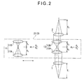
- Fig. 1 shows an exemplary embodiment of an optical unit of the invention and Fig. 2 is an illustration showing switched magnification.
- An optical unit includes: an objective lens 1; an imaging lens 2 that is arranged on an optical axis of the objective lens 1 and images a light beam output from the objective lens 1; a plurality of afocal optical systems 11 and 12 that are arranged between the objective lens 1 and the imaging lens 2 and have different afocal magnifications; and a switch 21 that shifts either one of the afocal optical systems 11 and 12 into the optical axis of the objective lens 1.
- the objective lens 1 and the imaging lens 2 are coaxial and are spaced apart with each other by an interval.
- the objective lens 1 and the imaging lens 2 are arranged space apart by an interval so that the optical axis of the imaging lens 2 is aligned with the optical axis of the objective lens 1.
- Afocal optical systems 11 and 12 include a first afocal optical system 11 and a second afocal optical system 12, both of which have different afocal magnifications.
- the first afocal optical system 11 includes a convex lens 11A that is arranged on the side at the objective lens 1 and has a focal length f3 and a convex lens 11B that is arranged on the side at the imaging lens 2 and has a focal length f4.
- the first afocal optical system 11 is provided by a Kepler type afocal optical system consisting of two convex lenses.
- the convex lenses 11 A and 11B are arranged so that a front focal position of the convex lens 11B coincides with a back focal position of the convex lens 11A.
- the second afocal optical system 12 includes a convex lens 12A that is arranged on the side at the objective lens 1 and has a focal length f5 and a convex lens 12B that is arranged on the side at the imaging lens 2 and has a focal length f6.
- the second afocal optical system 12 is provided by a Kepler type afocal optical system consisting of two convex lenses.
- a switch 21 includes a slide mechanism 3 that linearly slides the first afocal optical system 11 and the second afocal optical system 12 in a direction substantially perpendicular to the optical axis of the objective lens 1.
- the slide mechanism includes a slider that slides in a direction perpendicular to the optical axis of the objective lens 1 and a guiding mechanism that guides the slider, where the first afocal optical system 11 and the second afocal optical system 12 are arranged in the sliding direction of the slider with an interval. Accordingly, when the slider is slid in the direction perpendicular to the optical axis of the objective lens 1, either one of afocal optical systems 11 and 12 is shifted into the optical axis of the objective lens 1.
- an illumination light may be incident on the half mirrors, for instance, from the direction perpendicular to the optical axis of the objective lens 1 by inserting the half mirrors between the objective lens 1 and the afocal optical systems 11 and 12.
- an imaging device such as CCD camera is arranged at an imaging position of the imaging lens 2.
- ⁇ ⁇ 1 f ⁇ 2 / f ⁇ 1 ⁇ ⁇ ⁇ 1
- the slide mechanism 3 is slid to shift the second afocal optical system 12 into the optical axis of the objective lens 1.
- the optical axis of the second optical system 12 is sometimes misaligned with the optical axis of the objective lens 1. Even if the optical axis of the second optical system 12 is misaligned with the optical axis of the objective lens 1, a parallel light beam from the second optical system 12 always images at the center of the optical axis of the imaging lens 2, thereby minimizing a deviation of the focus from the center of the imaging lens.
- the first afocal optical system 11 and the second optical system 12, both of which have different magnifications, are arranged between the objective lens 1 and the imaging lens 2 with the switch 21 provided for shifting either one of the first afocal optical system 11 and the second afocal optical system 12 into the optical axis of the objective lens 1.
- the switch 21 By switching operation with the switch 21 to shift either one of the first afocal optical system 11 and the second optical system 12 into the optical axis of the objective lens 1, the magnification can be switched.
- optical unit of the above embodiment does not require branched optical path, so that light quantity does not decrease and the economic burden by additionally mounting an imaging device such as a camera is small.
- the invention is not limited to the forgoing exemplary embodiment, but includes modifications, improvements and the like within the range in which an object of the invention can be achieved.
- the afocal optical systems 11 and 12 are provided by a Kepler type consisting of the two convex lenses 11A and 11B and 12A and 12 B, but the structure is not limited to this.
- a Galileo type afocal optical system consisting of a concave lens and convex lens may be used.
- the afocal optical systems 11 and 12 are not limited to ones consisting of two lenses, but may be a zoom optical system or may be provided within the objective lens 1 and/or the imaging lens 2.
- the two afocal optical systems 11 and 12 are provided, either one of which is switched onto the optical axis of the objective lens 1.
- three or more afocal optical systems may be provided.
- the switch 21 includes the slide mechanism 3, but the structure is not limited to this.
- the turret mechanism may be used to move the afocal optical systems 11 and 12 in an arc to shift. If the turret mechanism is used to shift the afocal optical system as the number thereof increases, more afocal optical systems can be provided in a small space.
Landscapes
- Physics & Mathematics (AREA)
- General Physics & Mathematics (AREA)
- Optics & Photonics (AREA)
- Microscoopes, Condenser (AREA)
- Lenses (AREA)
- Instruments For Measurement Of Length By Optical Means (AREA)
Abstract
An optical unit includes: an objective lens (1); an imaging lens (2) that is arranged in the optical axis of the objective lens (1) and images a light beam output from the objective lens (1); a plurality of afocal optical systems (11, 12) that are arranged between the objective lens (1) and the imaging lens (2) and have different afocal magnifications (α1, α2); and a switch (21) that shifts either one of the afocal optical systems (11, 12) to be aligned with the optical axis of the objective lens (1).
Description
- The present invention relates to an optical unit and a measuring instrument. Specifically, it relates to an optical unit and a measuring instrument that can change optical magnification.
- Conventionally, various methods for changing optical magnification have been used in an image measuring instrument, an optical instrument and the like.
- An optical system that forms an image with the use of an
objective lens 1 and animaging lens 2 as shown inFig. 3 is called an infinity-correction optical system. When a focal length of theobjective lens 1 is f1 and a focal length of theimaging lens 2 is f2, optical magnification β is expressed by the formula:
objective lens 1 is fixed, the optical magnification β can be changed by changing the focal length f2 of theimaging lens 2. - In order to change the focal length f2 of the
imaging lens 2, a lens switching method that switches theimaging lens 2 and an optical path switching method that switches an optical path from theobjective lens 1 are known. - The former lens switching method shifts
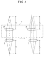
imaging lenses objective lens 1 with the use of aslide mechanism 3 which slides in a direction perpendicular to the optical axis of theobjective lens 1 as shown inFig. 4 , or with the use of a turret mechanism (see, for instance, Document 1:JP-A-09-304682 - The latter optical path switching method branches a light beam from the
objective lens 1 into two optical paths by using two half mirrors as shown inFig. 5 . In the respective branched optical paths, theimaging lenses mechanical shutters mechanical shutters - However, the conventional magnification switching methods have disadvantage as follows.
- In the former lens switching method, the mechanical accuracy (including repeatability) of the slide mechanism and the turret mechanism is limited, so that optical axes of the
imaging lenses 2B 1 are misaligned with the optical axis of the objective lens in switching the magnification. Consequently, the focal position is not at the center of the imaging lens, so that a highly accurate measurement is not expected. - In the latter optical path switching method, the
imaging lenses imaging lenses objective lens 1 in switching the magnification. However, the optical path requires to be branched by thehalf mirrors 4 and 5, resulting in decrease in light quantity. In addition, an imaging device such as a camera requires to be arranged correspondingly to each of theimaging lenses - An object of the invention is to solve the above disadvantages and to provide an optical unit and a measuring instrument that minimize influence caused by a deviation between optical axes in switching the magnification so that a highly accurate measurement can be achieved without incurring economic burden.
- An optical unit of the invention includes: an objective lens; an imaging lens that is arranged on the optical axis of the objective lens and images a light beam output from the objective lens; a plurality of afocal optical systems that are arranged between the objective lens and the imaging lens and have different afocal magnifications; and a switch that shifts one of the afocal optical systems into the optical axis of the objective lens.
- According to such an arrangement, one of the plurality of the afocal optical systems is shifted to be aligned with the optical axis of the objective lens by the switching operation with the switch in switching the magnification. When a focal length of the objective lens is f1, a focal length of the imaging lens is f2 and an afocal magnification of the afocal optical system is α, an optical magnification β of the optical unit is expressed by the formula:

- Even if the optical axes of the afocal optical systems are misaligned with the optical axes of the objective lens and the imaging lens in the switching operation, parallel light beams from the afocal optical systems always image at the center of the optical axis of the imaging lens, thereby minimizing a deviation of the focus from the center of the imaging lens. Accordingly, the highly accurate measurement can be achieved.
- Further, since the optical path is not branched, the light quantity does not decrease and the economic burden incurred by additionally mounting an imaging device such as a camera is small.
- In the optical unit of the above aspect of the invention, it is preferable that the switch is provided by one of a slide mechanism that linearly moves the afocal optical systems in a direction substantially perpendicular to the optical axis of the objective lens and a turret mechanism that moves the afocal optical systems in an arc.
- According to such an arrangement, even if the slide mechanism and the turret mechanism do not have a high mechanical accuracy including repeatability, influence caused by a deviation of the optical axis can be reduced, so that the slide mechanism and the turret mechanism can be manufactured easily and with low cost. Consequently, the cost of the optical unit can be reduced as a whole.
- The measuring instrument according to another aspect of the invention includes one of the optical units described above.
- Herein, the measuring instrument includes an image measuring instrument and an optical measuring microscope.
- According to such an arrangement, an image measuring instrument and an optical measuring microscope that can achieve the above advantage can be provided.
-
-
Fig. 1 shows an exemplary embodiment of an optical unit of the invention. -
Fig. 2 is an illustration showing switched magnification in the above embodiment. -
Fig. 3 shows an infinity-correction optical system. -
Fig. 4 shows a conventional lens-switching method in switching the magnification. -
Fig. 5 shows a conventional optical path switching method in switching the magnification. -
Fig. 1 shows an exemplary embodiment of an optical unit of the invention andFig. 2 is an illustration showing switched magnification. - An optical unit includes: an
objective lens 1; animaging lens 2 that is arranged on an optical axis of theobjective lens 1 and images a light beam output from theobjective lens 1; a plurality of afocaloptical systems objective lens 1 and theimaging lens 2 and have different afocal magnifications; and aswitch 21 that shifts either one of the afocaloptical systems objective lens 1. - The
objective lens 1 and theimaging lens 2 are coaxial and are spaced apart with each other by an interval. In other words, theobjective lens 1 and theimaging lens 2 are arranged space apart by an interval so that the optical axis of theimaging lens 2 is aligned with the optical axis of theobjective lens 1. - Afocal
optical systems optical system 11 and a second afocaloptical system 12, both of which have different afocal magnifications. - The first afocal
optical system 11 includes aconvex lens 11A that is arranged on the side at theobjective lens 1 and has a focal length f3 and aconvex lens 11B that is arranged on the side at theimaging lens 2 and has a focal length f4. In short, the first afocaloptical system 11 is provided by a Kepler type afocal optical system consisting of two convex lenses. Theconvex lenses convex lens 11B coincides with a back focal position of theconvex lens 11A. Accordingly, an afocal magnification α1 of the first afocaloptical system 11 is expressed by the formula:
The second afocaloptical system 12 includes aconvex lens 12A that is arranged on the side at theobjective lens 1 and has a focal length f5 and aconvex lens 12B that is arranged on the side at theimaging lens 2 and has a focal length f6. In short, the second afocaloptical system 12 is provided by a Kepler type afocal optical system consisting of two convex lenses. Theconvex lenses convex lens 12B coincides with a back focal position of theconvex lens 12A. Accordingly, an afocal magnification α2 of the second afocaloptical system 12 is expressed by the formula: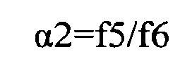
A switch 21 includes aslide mechanism 3 that linearly slides the first afocaloptical system 11 and the second afocaloptical system 12 in a direction substantially perpendicular to the optical axis of theobjective lens 1. - A known slide mechanisms may be used for the
slide mechanism 3. For example, the slide mechanism includes a slider that slides in a direction perpendicular to the optical axis of theobjective lens 1 and a guiding mechanism that guides the slider, where the first afocaloptical system 11 and the second afocaloptical system 12 are arranged in the sliding direction of the slider with an interval. Accordingly, when the slider is slid in the direction perpendicular to the optical axis of theobjective lens 1, either one of afocaloptical systems objective lens 1. - Though not shown in
Figs. 1 and2 , an illumination light may be incident on the half mirrors, for instance, from the direction perpendicular to the optical axis of theobjective lens 1 by inserting the half mirrors between theobjective lens 1 and the afocaloptical systems - Further, for an imaging measuring instrument, an imaging device such as CCD camera is arranged at an imaging position of the
imaging lens 2. - In a state of
Fig. 1 where the afocal magnification of the first afocaloptical system 11 is α1, the magnification β1 of the optical unit is expressed by the formula:
slide mechanism 3 is slid to shift the second afocaloptical system 12 into the optical axis of theobjective lens 1. - Consequently, as shown in
Fig. 2 , the optical axis of the secondoptical system 12 is sometimes misaligned with the optical axis of theobjective lens 1. Even if the optical axis of the secondoptical system 12 is misaligned with the optical axis of theobjective lens 1, a parallel light beam from the secondoptical system 12 always images at the center of the optical axis of theimaging lens 2, thereby minimizing a deviation of the focus from the center of the imaging lens. - In a state of
Fig. 2 where the afocal magnification of the second afocaloptical system 12 is α2, the magnification β2 of the optical unit is expressed by the formula:
- In the above embodiment, the first afocal
optical system 11 and the secondoptical system 12, both of which have different magnifications, are arranged between theobjective lens 1 and theimaging lens 2 with theswitch 21 provided for shifting either one of the first afocaloptical system 11 and the second afocaloptical system 12 into the optical axis of theobjective lens 1. By switching operation with theswitch 21 to shift either one of the first afocaloptical system 11 and the secondoptical system 12 into the optical axis of theobjective lens 1, the magnification can be switched. - Even if the optical axes of the afocal
optical systems objective lens 1 and theimaging lens 2, parallel light beams from the afocaloptical systems imaging lens 2, thereby minimizing a deviation of the focus from the center of the imaging lens. Accordingly, highly accurate measurement can be achieved. - Further, the optical unit of the above embodiment does not require branched optical path, so that light quantity does not decrease and the economic burden by additionally mounting an imaging device such as a camera is small.
- Moreover, according to an arrangement of the image measuring instrument provided with the above optical unit, a highly accurate measuring instrument can be economically provided.
- The invention is not limited to the forgoing exemplary embodiment, but includes modifications, improvements and the like within the range in which an object of the invention can be achieved.
- In the forgoing exemplary embodiment, the afocal
optical systems convex lenses - Further, the afocal
optical systems objective lens 1 and/or theimaging lens 2. - In the forgoing exemplary embodiment, the two afocal
optical systems objective lens 1. However, three or more afocal optical systems may be provided. - In the forgoing exemplary embodiment, the
switch 21 includes theslide mechanism 3, but the structure is not limited to this. For example, the turret mechanism may be used to move the afocaloptical systems
Claims (3)
- An optical unit, comprising:an objective lens (1);an imaging lens (2) that is arranged on an optical axis of the objective lens (1) and images a light beam output from the objective lens (1);a plurality of afocal optical systems (11, 12) that are arranged between the objective lens (1) and the imaging lens (2) and differ in afocal magnification; anda switch (21) that shifts one of the afocal optical systems (11, 12) into the optical axis of the objective lens (1).
- The optical unit according to claim 1,
wherein the switch (21) is provided by either one of a slide mechanism (3) that linearly moves the afocal optical systems (11, 12) in a direction substantially perpendicular to the optical axis of the objective lens (1), and a turret mechanism that moves the afocal optical systems (11, 12) in an arc. - A measuring instrument, comprising the optical unit according to claim 1 or claim 2.
Applications Claiming Priority (1)
| Application Number | Priority Date | Filing Date | Title |
|---|---|---|---|
| JP2008071795A JP2009229547A (en) | 2008-03-19 | 2008-03-19 | Optical unit and measuring instrument |
Publications (1)
| Publication Number | Publication Date |
|---|---|
| EP2103981A1 true EP2103981A1 (en) | 2009-09-23 |
Family
ID=40548806
Family Applications (1)
| Application Number | Title | Priority Date | Filing Date |
|---|---|---|---|
| EP09003272A Withdrawn EP2103981A1 (en) | 2008-03-19 | 2009-03-06 | Optical unit and measuring instrument with plural afocal optical systems for changing magnification |
Country Status (4)
| Country | Link |
|---|---|
| US (1) | US20090237650A1 (en) |
| EP (1) | EP2103981A1 (en) |
| JP (1) | JP2009229547A (en) |
| CN (1) | CN101539656A (en) |
Families Citing this family (3)
| Publication number | Priority date | Publication date | Assignee | Title |
|---|---|---|---|---|
| JP5734713B2 (en) * | 2011-03-23 | 2015-06-17 | オリンパス株式会社 | Observation optical system |
| CN104483740B (en) * | 2014-11-20 | 2017-07-14 | 中国工程物理研究院激光聚变研究中心 | Axicon precision axis fixation method |
| WO2021150750A1 (en) * | 2020-01-21 | 2021-07-29 | Volfson Leo | Afocal adapter for an optical device |
Citations (11)
| Publication number | Priority date | Publication date | Assignee | Title |
|---|---|---|---|---|
| GB724821A (en) * | 1952-03-31 | 1955-02-23 | Leitz Ernst Gmbh | Improvements in or relating to binocular magnifying devices |
| GB843888A (en) * | 1958-06-26 | 1960-08-10 | Arthur Abbey | Improvements in or relating to stereoscopic microscopes |
| US3402976A (en) * | 1964-07-24 | 1968-09-24 | Zeiss Stiftung | Stereoscopic double-microscope |
| GB1214265A (en) * | 1968-04-05 | 1970-12-02 | Zeiss Carl | Surgical microscope with a tele-objective lens |
| DE2439820A1 (en) * | 1974-08-20 | 1976-03-04 | Moeller J D Optik | Floor or ceiling mounted microscope for micro-surgery - can be focused without microscope movement |
| US5528416A (en) * | 1995-06-05 | 1996-06-18 | Martin Marietta Corporation | Compact multiple field-of-view attachment |
| JPH09304682A (en) | 1996-05-16 | 1997-11-28 | Mitsutoyo Corp | Optical measuring device |
| EP0815801A2 (en) * | 1996-06-25 | 1998-01-07 | Carl Zeiss | OCT-assisted surgical microscope with multi-coordinate manipulator |
| GB2332755A (en) * | 1997-12-24 | 1999-06-30 | Gersan Ets | Viewing marks on the surface of a gemstone or diamond |
| US20060176550A1 (en) * | 2005-02-07 | 2006-08-10 | Christian Luecke | Tube for a viewing device as well as a viewing device |
| EP1985227A1 (en) * | 2007-04-27 | 2008-10-29 | Haag-Streit Ag | Optical component for a stereo microscope |
Family Cites Families (1)
| Publication number | Priority date | Publication date | Assignee | Title |
|---|---|---|---|---|
| US4155622A (en) * | 1974-08-20 | 1979-05-22 | J. D. Moller Optische Werke Gmbh | Microscope with internal focussing |
-
2008
- 2008-03-19 JP JP2008071795A patent/JP2009229547A/en active Pending
-
2009
- 2009-02-27 US US12/379,750 patent/US20090237650A1/en not_active Abandoned
- 2009-03-06 EP EP09003272A patent/EP2103981A1/en not_active Withdrawn
- 2009-03-13 CN CN200910118477A patent/CN101539656A/en active Pending
Patent Citations (11)
| Publication number | Priority date | Publication date | Assignee | Title |
|---|---|---|---|---|
| GB724821A (en) * | 1952-03-31 | 1955-02-23 | Leitz Ernst Gmbh | Improvements in or relating to binocular magnifying devices |
| GB843888A (en) * | 1958-06-26 | 1960-08-10 | Arthur Abbey | Improvements in or relating to stereoscopic microscopes |
| US3402976A (en) * | 1964-07-24 | 1968-09-24 | Zeiss Stiftung | Stereoscopic double-microscope |
| GB1214265A (en) * | 1968-04-05 | 1970-12-02 | Zeiss Carl | Surgical microscope with a tele-objective lens |
| DE2439820A1 (en) * | 1974-08-20 | 1976-03-04 | Moeller J D Optik | Floor or ceiling mounted microscope for micro-surgery - can be focused without microscope movement |
| US5528416A (en) * | 1995-06-05 | 1996-06-18 | Martin Marietta Corporation | Compact multiple field-of-view attachment |
| JPH09304682A (en) | 1996-05-16 | 1997-11-28 | Mitsutoyo Corp | Optical measuring device |
| EP0815801A2 (en) * | 1996-06-25 | 1998-01-07 | Carl Zeiss | OCT-assisted surgical microscope with multi-coordinate manipulator |
| GB2332755A (en) * | 1997-12-24 | 1999-06-30 | Gersan Ets | Viewing marks on the surface of a gemstone or diamond |
| US20060176550A1 (en) * | 2005-02-07 | 2006-08-10 | Christian Luecke | Tube for a viewing device as well as a viewing device |
| EP1985227A1 (en) * | 2007-04-27 | 2008-10-29 | Haag-Streit Ag | Optical component for a stereo microscope |
Also Published As
| Publication number | Publication date |
|---|---|
| US20090237650A1 (en) | 2009-09-24 |
| CN101539656A (en) | 2009-09-23 |
| JP2009229547A (en) | 2009-10-08 |
Similar Documents
| Publication | Publication Date | Title |
|---|---|---|
| US6930705B2 (en) | Image search device | |
| CN102301268B (en) | Imaging optical system, and microscope apparatus and stereo microscope apparatus, having the imaging optical system | |
| US9429740B2 (en) | Telecentric modular zoom system | |
| US6985288B2 (en) | Illumination apparatus for microscope and microscope | |
| US6707617B2 (en) | Telecentric lens system and image measuring device | |
| US20050134970A1 (en) | Afocal zoom system | |
| US20090237650A1 (en) | Optical unit and measuring instrument | |
| JP7362904B2 (en) | Object imaging device and imaging method | |
| US8294986B2 (en) | Observation device | |
| JP6595576B2 (en) | Zoom microscope | |
| EP2682802B1 (en) | Attachment image acquisition apparatus for microscopes | |
| KR102885022B1 (en) | Variable-zoom imaging device | |
| JP3349711B2 (en) | Automatic focus detection device | |
| JPH11183124A (en) | Image inspection and measurement equipment | |
| EP3396431A1 (en) | Monocular microscope for capturing stereoscopic image | |
| US6804051B2 (en) | Optical instrument having a binocular viewing port | |
| EP1762874A2 (en) | Lens apparatus comprising a focus-state detecting unit | |
| US6943961B2 (en) | Zoom lens system and focus adjustment method thereof | |
| US20190113730A1 (en) | Observation apparatus | |
| US20250035826A1 (en) | Variable focal length lens device | |
| JP2001356393A (en) | Zoom finder device | |
| US12517005B2 (en) | Apparatus and method for measuring an optical property of an optical system | |
| US20070058247A1 (en) | Microscope with focusing device for observing depth structures in objects | |
| JP5298782B2 (en) | Lens barrel and imaging device | |
| JP2713403B2 (en) | Optical device capable of changing magnification |
Legal Events
| Date | Code | Title | Description |
|---|---|---|---|
| PUAI | Public reference made under article 153(3) epc to a published international application that has entered the european phase |
Free format text: ORIGINAL CODE: 0009012 |
|
| AK | Designated contracting states |
Kind code of ref document: A1 Designated state(s): AT BE BG CH CY CZ DE DK EE ES FI FR GB GR HR HU IE IS IT LI LT LU LV MC MK MT NL NO PL PT RO SE SI SK TR |
|
| AX | Request for extension of the european patent |
Extension state: AL BA RS |
|
| AKX | Designation fees paid | ||
| STAA | Information on the status of an ep patent application or granted ep patent |
Free format text: STATUS: THE APPLICATION IS DEEMED TO BE WITHDRAWN |
|
| 18D | Application deemed to be withdrawn |
Effective date: 20100324 |
|
| REG | Reference to a national code |
Ref country code: DE Ref legal event code: 8566 |