EP2103954A1 - Adaptive clutter signal filtering in an ultrasound system - Google Patents
Adaptive clutter signal filtering in an ultrasound system Download PDFInfo
- Publication number
- EP2103954A1 EP2103954A1 EP09003732A EP09003732A EP2103954A1 EP 2103954 A1 EP2103954 A1 EP 2103954A1 EP 09003732 A EP09003732 A EP 09003732A EP 09003732 A EP09003732 A EP 09003732A EP 2103954 A1 EP2103954 A1 EP 2103954A1
- Authority
- EP
- European Patent Office
- Prior art keywords
- cutoff frequency
- ultrasound system
- signals
- processing unit
- signal processing
- Prior art date
- Legal status (The legal status is an assumption and is not a legal conclusion. Google has not performed a legal analysis and makes no representation as to the accuracy of the status listed.)
- Granted
Links
Images


Classifications
-
- A—HUMAN NECESSITIES
- A61—MEDICAL OR VETERINARY SCIENCE; HYGIENE
- A61B—DIAGNOSIS; SURGERY; IDENTIFICATION
- A61B8/00—Diagnosis using ultrasonic, sonic or infrasonic waves
-
- G—PHYSICS
- G01—MEASURING; TESTING
- G01S—RADIO DIRECTION-FINDING; RADIO NAVIGATION; DETERMINING DISTANCE OR VELOCITY BY USE OF RADIO WAVES; LOCATING OR PRESENCE-DETECTING BY USE OF THE REFLECTION OR RERADIATION OF RADIO WAVES; ANALOGOUS ARRANGEMENTS USING OTHER WAVES
- G01S15/00—Systems using the reflection or reradiation of acoustic waves, e.g. sonar systems
- G01S15/88—Sonar systems specially adapted for specific applications
- G01S15/89—Sonar systems specially adapted for specific applications for mapping or imaging
- G01S15/8906—Short-range imaging systems; Acoustic microscope systems using pulse-echo techniques
- G01S15/8979—Combined Doppler and pulse-echo imaging systems
- G01S15/8981—Discriminating between fixed and moving objects or between objects moving at different speeds, e.g. wall clutter filter
-
- G—PHYSICS
- G01—MEASURING; TESTING
- G01S—RADIO DIRECTION-FINDING; RADIO NAVIGATION; DETERMINING DISTANCE OR VELOCITY BY USE OF RADIO WAVES; LOCATING OR PRESENCE-DETECTING BY USE OF THE REFLECTION OR RERADIATION OF RADIO WAVES; ANALOGOUS ARRANGEMENTS USING OTHER WAVES
- G01S7/00—Details of systems according to groups G01S13/00, G01S15/00, G01S17/00
- G01S7/52—Details of systems according to groups G01S13/00, G01S15/00, G01S17/00 of systems according to group G01S15/00
- G01S7/52017—Details of systems according to groups G01S13/00, G01S15/00, G01S17/00 of systems according to group G01S15/00 particularly adapted to short-range imaging
- G01S7/5205—Means for monitoring or calibrating
-
- G—PHYSICS
- G01—MEASURING; TESTING
- G01S—RADIO DIRECTION-FINDING; RADIO NAVIGATION; DETERMINING DISTANCE OR VELOCITY BY USE OF RADIO WAVES; LOCATING OR PRESENCE-DETECTING BY USE OF THE REFLECTION OR RERADIATION OF RADIO WAVES; ANALOGOUS ARRANGEMENTS USING OTHER WAVES
- G01S7/00—Details of systems according to groups G01S13/00, G01S15/00, G01S17/00
- G01S7/52—Details of systems according to groups G01S13/00, G01S15/00, G01S17/00 of systems according to group G01S15/00
- G01S7/52017—Details of systems according to groups G01S13/00, G01S15/00, G01S17/00 of systems according to group G01S15/00 particularly adapted to short-range imaging
- G01S7/52053—Display arrangements
- G01S7/52057—Cathode ray tube displays
- G01S7/5206—Two-dimensional coordinated display of distance and direction; B-scan display
- G01S7/52063—Sector scan display
Definitions
- the present disclosure relates to signal processing, and more particularly to clutter signal filtering in an ultrasound system.
- an ultrasound system has been extensively used in the medical field due to its non-invasive and non-destructive nature.
- Modem high-performance ultrasound imaging diagnostic systems and techniques are commonly used to produce two- or three-dimensional ultrasound images of internal features of patients.
- the ultrasound system operates in various image modes such as a brightness mode, a Doppler mode and the like to acquire ultrasound images for diagnosis.
- the ultrasound system provides a color flow image showing velocities of moving objects such as blood flow, a heart, etc.
- the color flow image may be formed based on Doppler signals obtained by alternately transmitting and receiving ultrasound signals to and from a target object.
- the Doppler signals may contain low frequency signals due to the motion of cardiac walls or valves of a heart.
- the low frequency signals (so-called clutter signals) have amplitude of over 100 times than that of normal Doppler signals obtained from the blood flow.
- the clutter signals may be an obstacle to accurately detect velocities of the blood flow. Thus, it is required to remove the clutter signals from the Doppler signals for accurate detection.
- the ultrasound system adopts clutter filters, which are types of a high pass filter, to remove the clutter signals.
- the clutter filters of a conventional ultrasound system remove the clutter signals with a specific cutoff frequency.
- the cutoff frequency is highly set, then the Doppler signals of a relatively low frequency may be also cut off with the clutter signals. Thus, it may be difficult to accurately detect the velocities of the blood flow.
- an ultrasound system comprises: a Tx/Rx unit configured to transmit ultrasound signals to a target object and receive echoes reflected from the target object; a signal processing unit configured to process the received echoes to provide 2-dimensional image data of the target object, the 2-dimensional image data being representative of a 2-dimensional image; and an input unit configured to enable a user to set a region of interest (ROI) on the 2-dimensional image of the target object, wherein the Tx/Rx unit and the signal processing unit are further configured to operate such that Doppler mode image pixel data corresponding to the ROI is obtained, and wherein the signal processing unit is further configured to set filter cutoff frequencies based on characteristics of the Doppler mode image pixel data and filter the Doppler mode image pixel data with the set filter cutoff frequencies to output filtered pixel data with clutter signals filtered.
- ROI region of interest
- a method of setting filters in an ultrasound system comprises: a) using the Tx/Rx unit within the ultrasound system to transmit ultrasound signals to a target object and receive echoes reflected from the target object; b) using the signal processing unit within the ultrasound system to process the received echoes to provide 2-dimensional image data of the target object, the 2-dimensional image data being representative of a 2-dimensional image; c) using an input unit within the ultrasound system to enable a user to set a region of interest (ROI) on the 2-dimensional image of the target object; d) using the Tx/Rx unit and the signal processing unit within the ultrasound system to operate such that Doppler mode image pixel data corresponding to the ROI is obtained; and e) using the signal processing unit within the ultrasound system to set filter cutoff frequencies based on characteristics of the Doppler mode image pixel data and filter the Doppler mode image pixel data with the set filter cutoff frequencies to output filtered pixel
- ROI region of interest
- the ultrasound system 100 may include a user input unit 110 allowing a user to input setup information of a region of interest (ROI).
- the ROI may include a color box and the setup information of the ROI may include information upon position and size of the ROI.
- the ultrasound system 100 may further include a control unit 120.
- the control unit 120 may be configured to control transmission/reception (Tx/Rx) of ultrasound signals based on the setup information of the ROI.
- the control unit 120 may control Tx/Rx of the ultrasound signals such that Tx/Rx of first ultrasound signals "B" for a B-mode image and second ultrasound signals "D" for a Doppler mode image may be alternately performed, as illustrated in FIG 2 .
- the Doppler mode image may be a color flow image for the ROI set on the B-mode image.
- the control unit 120 may control the entire operations of the ultrasound system 100.
- the ultrasound system 100 may further include a Tx/Rx unit 130.
- the Tx/Rx unit 130 may transmit/receive the first ultrasound signals to/from the target object in a B mode, thereby outputting first receive signals.
- the Tx/Rx unit 130 may also transmit/receive the second ultrasound signals to/from the target object in the Doppler mode, thereby outputting second receive signals.
- the Tx/Rx of the first and second ultrasound signals may be alternately carried out at a repletion frequency.
- the second receive signal may include Doppler signals and clutter signals.
- the Doppler signals may be obtained based on echo signals reflected from the blood flow.
- the Doppler signals have characteristics of a relatively high frequency and a weak intensity.
- the clutter signals may be obtained based on echo signals reflected from a cardiac wall or a valve of a heart.
- the clutter signals have characteristics of a relatively low frequency and a high intensity.
- the Tx/Rx unit 130 may include a probe (not shown) for generating the ultrasound signal and the receive signal.
- the Tx/Rx unit 130 may further include a beam former (not shown) for transmit focusing and receive focusing.
- the ultrasound system 100 may further include a storage unit 140.
- the ultrasound system 100 may store the second receive signals outputted from the Tx/Rx unit 130.
- the second receive signals may represent Doppler mode image pixel data corresponding to the ROI.
- the storage unit 140 may store information upon a plurality of cutoff frequencies for removing the clutter signals.
- the storage unit 140 may include a first section (not shown) for storing the second receive signals and a second section (not shown) for storing the information upon the plurality of cutoff frequencies.
- the ultrasound system 100 may further include a signal processing unit 150.
- the signal processing unit 150 may be configured to process the first receive signals to provide 2-dimensional image data representing a 2-dimensional ultrasound image of the target object and set a plurality of filters with the cutoff frequencies to remove the clutter signals from pixel signals within a region of interest (ROI) set on the 2-dimensional ultrasound image based on the setup information.
- the signal processing unit 150 may be further configured to perform signal processing upon the first receive signal for image optimization (e.g., gain adjustment, etc.).
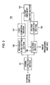
- FIG. 3 is a block diagram of an illustrative embodiment of the signal processing unit 150.
- FIG 4 is a flowchart showing an example of setting the cutoff frequencies.
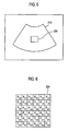
- FIG 5 is a schematic diagram showing an example of ROI set on the 2-dimensional ultrasound image.
- FIG 6 is a schematic diagram showing an example of pixels within the region of interest.
- the signal processing unit 150 may include a signal extracting section 151.
- the signal extracting section 151 may be configured to extract the second receive signals (i.e., Doppler mode image pixel data) from the storage unit 140 at step S102.
- the signal processing unit 151 may further include a reference pixel setting section 152.
- the reference pixel setting section 152 may select a reference pixel from pixels contained within the ROI and output a signal corresponding to the reference pixel ("reference pixel signal”) from the Doppler mode image pixel data) at step S106.
- the reference pixel setting section 152 may divide the pixels within the ROI into a plurality of groups. Each of the groups may include a predetermined number of neighboring pixels.
- the reference pixel setting section 152 may select a reference pixel from each of the groups. For example, assuming that pixels P 0,0 - P 5,5 exist within the ROI, the reference pixel setting section 152 may divide the pixels P 0,0 - P 5,5 into four pixel groups, each having a size of 3 X 3, as follows.
- First pixel group ⁇ P 0,0 , P 0 , 1 , P 0,2 , P 1,0 , P 1,1 , P 1,2 , P 2,0 , P 2,1 , P 2,2 ⁇
- Second pixel group ⁇ P 0,3 , P 0,4 , P 0,5 , P 1,3 , P 1,4 , P 1,5 , P 2,3 , P 2,4 , P 2,5 ⁇
- Third pixel group ⁇ P 3,0 , P 3,1 , P 3,2 , P 4,0 , P 4,1 , P 4,2 , P 5,0 , P 5,1 , P 5,2 ⁇
- Four pixel group ⁇ P 3,3 , P 3,4 , P 3,5 , P 4,3 , P 4,4 , P 4,5 , P 5,3 , P 5,4 , P 5,5 ⁇
- the reference pixel setting section 152 may select a pixel P 1,1 from the first pixel group, a pixel P 1,4 from the second pixel group, a pixel P 4,1 from the third pixel group, and a pixel P 4,4 from the fourth pixel group as reference pixels, respectively.
- the reference pixel setting section 152 may output reference pixel signals.
- the signal processing unit 150 may further include a first computing section 153.
- the first computing section 153 may receive the reference pixel signals and compute a first power, a first mean frequency and a distribution of the reference pixel signals by using auto correlation at step S108. Also, the signal processing unit 150 may compute a first standard deviation by using the computed distribution at S108.
- the signal processing unit 150 may further include a cutoff frequency setting section 154.
- the cutoff frequency setting section 154 may compute a first cutoff frequency of each of the filters corresponding to the pixels within the ROI 220 by using the first mean frequency at S110.
- the cutoff frequency setting section 155 may multiply or add a preset weight to the mean frequency to compute the first cutoff frequency of each of the filters.
- the signal processing unit 150 may further include a filtering section 155.
- the filtering section 155 may set filters for removing the clutter signals from each of the pixels within the ROI 220 at step S112.
- the filtering section 155 may include clutter filters.
- the filtering section 155 may set a cutoff frequency of each of the filters by using the first cutoff frequency at step S114. When the first cutoff frequency is a cutoff frequency corresponding to the reference pixel of each of the groups, the filtering section 155 may set an identical cutoff frequency to each of the filters corresponding to each of the pixels in the pixel groups.
- the filtering section 155 may filter the clutter signals from the second receive signals to thereby extract the Doppler signals at step S116.
- the signal processing unit 150 may further include a second computing section 156.
- the second computing section 156 may be configured to receive the signals with the clutter signals filtered ("filtering signals”) and compute a second power and a second mean frequency of the filtering signals at S118.
- the signal processing unit 150 may further include a cutoff frequency setting section 154.
- the cutoff frequency setting section 154 may check whether the first cutoff frequency is suitable by using the first power, the first mean frequency, the first standard deviation, the second power and the second mean frequency, i.e., whether the first cutoff frequency is suitable as a cutoff frequency of the filter of the filtering section 155 at S 120.
- the cutoff frequency setting section 154 may check whether the first cutoff frequency is suitable by applying the following equations. 2 nd mean frequency ⁇ 1 st mean frequency + 1 st standard deviation + 1 st threshold 2 nd power ⁇ 1 st power ⁇ 2 nd threshold
- the first and second thresholds may be predetermined values by a user or in the ultrasound system.
- the first and second thresholds may be set to 0.3.
- the cutoff frequency setting section 154 may determine that the first cutoff frequency is suitable and finish the cutoff frequency setting. On the other hand, if the second mean frequency and the second power do not meet at least one of the equations (1) and (2), i.e., if it is determined that the first cutoff frequency is not suitable, then the cutoff frequency setting section 154 may compute a second cutoff frequency and set the second cutoff frequency as the first cutoff frequency at step S122. The steps S114 to S122 may be repeatedly carried out until equations (1) and (2) are satisfied.
- the ultrasound system may further include an image processing unit 160 and may form a 2-dimensional image and a Doppler mode image based on the first and second receive signals outputted from the signal processing unit 150, respectively.
- the ultrasound system may further include a display unit 170 for displaying the 2-dimensional image and the Doppler mode image.
- the cutoff frequency setting section 154 computes the first cutoff frequency by using the first means frequency and the filtering section 155 sets the cutoff frequency of each of the filters by using the first cutoff frequency
- the computation of the first cutoff frequency and the setting of the cutoff frequency are not limited thereto.
- the cutoff frequency setting section 154 may extract cutoff frequency information corresponding to the first mean frequency from the storage unit 140, while the filtering section 155 may set the cutoff frequency of each of the filters based on the extracted cutoff frequency information.
- the cutoff frequency of the clutter filter is automatically set based on the power and mean frequency of the clutter signals, the velocity of the blood flow may be accurately detected and the quality of the Doppler mode image may be enhanced.
Landscapes
- Engineering & Computer Science (AREA)
- Physics & Mathematics (AREA)
- Radar, Positioning & Navigation (AREA)
- Remote Sensing (AREA)
- Computer Networks & Wireless Communication (AREA)
- General Physics & Mathematics (AREA)
- Acoustics & Sound (AREA)
- Health & Medical Sciences (AREA)
- Life Sciences & Earth Sciences (AREA)
- Nuclear Medicine, Radiotherapy & Molecular Imaging (AREA)
- Molecular Biology (AREA)
- Pathology (AREA)
- Radiology & Medical Imaging (AREA)
- Biomedical Technology (AREA)
- Heart & Thoracic Surgery (AREA)
- Medical Informatics (AREA)
- Biophysics (AREA)
- Surgery (AREA)
- Animal Behavior & Ethology (AREA)
- General Health & Medical Sciences (AREA)
- Public Health (AREA)
- Veterinary Medicine (AREA)
- Ultra Sonic Daignosis Equipment (AREA)
Abstract
Description
- The present application claims priority from Korean Patent Application No.
10 2008 0025970 filed on March 20, 2008 - The present disclosure relates to signal processing, and more particularly to clutter signal filtering in an ultrasound system.
- Recently, an ultrasound system has been extensively used in the medical field due to its non-invasive and non-destructive nature. Modem high-performance ultrasound imaging diagnostic systems and techniques are commonly used to produce two- or three-dimensional ultrasound images of internal features of patients. In order to provide the ultrasound images, the ultrasound system operates in various image modes such as a brightness mode, a Doppler mode and the like to acquire ultrasound images for diagnosis.
- In the Doppler mode, the ultrasound system provides a color flow image showing velocities of moving objects such as blood flow, a heart, etc. The color flow image may be formed based on Doppler signals obtained by alternately transmitting and receiving ultrasound signals to and from a target object. The Doppler signals may contain low frequency signals due to the motion of cardiac walls or valves of a heart. The low frequency signals (so-called clutter signals) have amplitude of over 100 times than that of normal Doppler signals obtained from the blood flow. The clutter signals may be an obstacle to accurately detect velocities of the blood flow. Thus, it is required to remove the clutter signals from the Doppler signals for accurate detection. The ultrasound system adopts clutter filters, which are types of a high pass filter, to remove the clutter signals.
- The clutter filters of a conventional ultrasound system remove the clutter signals with a specific cutoff frequency. In such a case, if the cutoff frequency is highly set, then the Doppler signals of a relatively low frequency may be also cut off with the clutter signals. Thus, it may be difficult to accurately detect the velocities of the blood flow.
- Embodiments for setting cutoff frequencies of clutter filters based on power and mean frequency of clutter signals are disclosed herein. In one embodiment, by way of nonlimiting example, an ultrasound system comprises: a Tx/Rx unit configured to transmit ultrasound signals to a target object and receive echoes reflected from the target object; a signal processing unit configured to process the received echoes to provide 2-dimensional image data of the target object, the 2-dimensional image data being representative of a 2-dimensional image; and an input unit configured to enable a user to set a region of interest (ROI) on the 2-dimensional image of the target object, wherein the Tx/Rx unit and the signal processing unit are further configured to operate such that Doppler mode image pixel data corresponding to the ROI is obtained, and wherein the signal processing unit is further configured to set filter cutoff frequencies based on characteristics of the Doppler mode image pixel data and filter the Doppler mode image pixel data with the set filter cutoff frequencies to output filtered pixel data with clutter signals filtered.
- In another embodiment, a method of setting filters in an ultrasound system, the ultrasound system including a Tx/Rx unit, a storage unit and a signal processing unit, comprises: a) using the Tx/Rx unit within the ultrasound system to transmit ultrasound signals to a target object and receive echoes reflected from the target object; b) using the signal processing unit within the ultrasound system to process the received echoes to provide 2-dimensional image data of the target object, the 2-dimensional image data being representative of a 2-dimensional image; c) using an input unit within the ultrasound system to enable a user to set a region of interest (ROI) on the 2-dimensional image of the target object; d) using the Tx/Rx unit and the signal processing unit within the ultrasound system to operate such that Doppler mode image pixel data corresponding to the ROI is obtained; and e) using the signal processing unit within the ultrasound system to set filter cutoff frequencies based on characteristics of the Doppler mode image pixel data and filter the Doppler mode image pixel data with the set filter cutoff frequencies to output filtered pixel data with clutter signals filtered.
- The Summary is provided to introduce a selection of concepts in a simplified form that are further described below in the Detailed Description. This Summary is not intended to identify key or essential features of the claimed subject matter, nor is it intended to be used in determining the scope of the claimed subject matter.
-
- FIG. 1
- is a block diagram showing an illustrative embodiment of an ultrasound system.
- FIG 2
- is a timing diagram showing an example of Tx/Rx of ultrasound signals.
- FIG 3
- is a block diagram showing an illustrative embodiment of a signal processing unit.
- FIG. 4
- is a flowchart showing an example of setting the cutoff frequencies.
- FIG. 5
- is a schematic diagram showing an example of a region of interest set on a 2-dimensional ultrasound image.
- FIG 6
- is a schematic diagram showing an example of pixels within the region of interest.
- A detailed description may be provided with reference to the accompanying drawings. One of ordinary skill in the art may realize that the following description is illustrative only and is not in any way limiting. Other embodiments of the present invention may readily suggest themselves to such skilled persons having the benefit of this disclosure.
- Referring to
FIG. 1 , an illustrative embodiment of anultrasound system 100 is shown. As depicted, theultrasound system 100 may include auser input unit 110 allowing a user to input setup information of a region of interest (ROI). The ROI may include a color box and the setup information of the ROI may include information upon position and size of the ROI. - The
ultrasound system 100 may further include acontrol unit 120. Thecontrol unit 120 may be configured to control transmission/reception (Tx/Rx) of ultrasound signals based on the setup information of the ROI. Thecontrol unit 120 may control Tx/Rx of the ultrasound signals such that Tx/Rx of first ultrasound signals "B" for a B-mode image and second ultrasound signals "D" for a Doppler mode image may be alternately performed, as illustrated inFIG 2 . The Doppler mode image may be a color flow image for the ROI set on the B-mode image. Also, thecontrol unit 120 may control the entire operations of theultrasound system 100. - As shown in
FIG. 1 , theultrasound system 100 may further include a Tx/Rx unit 130. The Tx/Rx unit 130 may transmit/receive the first ultrasound signals to/from the target object in a B mode, thereby outputting first receive signals. The Tx/Rx unit 130 may also transmit/receive the second ultrasound signals to/from the target object in the Doppler mode, thereby outputting second receive signals. The Tx/Rx of the first and second ultrasound signals may be alternately carried out at a repletion frequency. The second receive signal may include Doppler signals and clutter signals. The Doppler signals may be obtained based on echo signals reflected from the blood flow. The Doppler signals have characteristics of a relatively high frequency and a weak intensity. The clutter signals may be obtained based on echo signals reflected from a cardiac wall or a valve of a heart. The clutter signals have characteristics of a relatively low frequency and a high intensity. In one embodiment, the Tx/Rx unit 130 may include a probe (not shown) for generating the ultrasound signal and the receive signal. The Tx/Rx unit 130 may further include a beam former (not shown) for transmit focusing and receive focusing. - The
ultrasound system 100 may further include astorage unit 140. In one embodiment, theultrasound system 100 may store the second receive signals outputted from the Tx/Rx unit 130. The second receive signals may represent Doppler mode image pixel data corresponding to the ROI. Also, thestorage unit 140 may store information upon a plurality of cutoff frequencies for removing the clutter signals. In one embodiment, thestorage unit 140 may include a first section (not shown) for storing the second receive signals and a second section (not shown) for storing the information upon the plurality of cutoff frequencies. - In one embodiment, the
ultrasound system 100 may further include asignal processing unit 150. Thesignal processing unit 150 may be configured to process the first receive signals to provide 2-dimensional image data representing a 2-dimensional ultrasound image of the target object and set a plurality of filters with the cutoff frequencies to remove the clutter signals from pixel signals within a region of interest (ROI) set on the 2-dimensional ultrasound image based on the setup information. Thesignal processing unit 150 may be further configured to perform signal processing upon the first receive signal for image optimization (e.g., gain adjustment, etc.). -
FIG. 3 is a block diagram of an illustrative embodiment of thesignal processing unit 150.FIG 4 is a flowchart showing an example of setting the cutoff frequencies.FIG 5 is a schematic diagram showing an example of ROI set on the 2-dimensional ultrasound image.FIG 6 is a schematic diagram showing an example of pixels within the region of interest. - The
signal processing unit 150 may include asignal extracting section 151. In one embodiment, thesignal extracting section 151 may be configured to extract the second receive signals (i.e., Doppler mode image pixel data) from thestorage unit 140 at step S102. Thesignal processing unit 151 may further include a referencepixel setting section 152. In one embodiment, the referencepixel setting section 152 may select a reference pixel from pixels contained within the ROI and output a signal corresponding to the reference pixel ("reference pixel signal") from the Doppler mode image pixel data) at step S106. In another embodiment, the referencepixel setting section 152 may divide the pixels within the ROI into a plurality of groups. Each of the groups may include a predetermined number of neighboring pixels. The referencepixel setting section 152 may select a reference pixel from each of the groups. For example, assuming that pixels P0,0- P5,5 exist within the ROI, the referencepixel setting section 152 may divide the pixels P0,0 - P5,5 into four pixel groups, each having a size of 3 X 3, as follows.
First pixel group = {P0,0, P0,1, P0,2, P1,0, P1,1, P1,2, P2,0, P2,1, P2,2}
Second pixel group = {P0,3, P0,4, P0,5, P1,3, P1,4, P1,5, P2,3, P2,4, P2,5}
Third pixel group = {P3,0, P3,1, P3,2, P4,0, P4,1, P4,2, P5,0, P5,1, P5,2}
Four pixel group = {P3,3, P3,4, P3,5, P4,3, P4,4, P4,5, P5,3, P5,4, P5,5} - For example, the reference
pixel setting section 152 may select a pixel P1,1 from the first pixel group, a pixel P1,4 from the second pixel group, a pixel P4,1 from the third pixel group, and a pixel P4,4 from the fourth pixel group as reference pixels, respectively. The referencepixel setting section 152 may output reference pixel signals. - The
signal processing unit 150 may further include afirst computing section 153. Thefirst computing section 153 may receive the reference pixel signals and compute a first power, a first mean frequency and a distribution of the reference pixel signals by using auto correlation at step S108. Also, thesignal processing unit 150 may compute a first standard deviation by using the computed distribution at S108. - The
signal processing unit 150 may further include a cutofffrequency setting section 154. The cutofffrequency setting section 154 may compute a first cutoff frequency of each of the filters corresponding to the pixels within theROI 220 by using the first mean frequency at S110. For example, the cutofffrequency setting section 155 may multiply or add a preset weight to the mean frequency to compute the first cutoff frequency of each of the filters. - The
signal processing unit 150 may further include afiltering section 155. Thefiltering section 155 may set filters for removing the clutter signals from each of the pixels within theROI 220 at step S112. In one embodiment, thefiltering section 155 may include clutter filters. Thefiltering section 155 may set a cutoff frequency of each of the filters by using the first cutoff frequency at step S114. When the first cutoff frequency is a cutoff frequency corresponding to the reference pixel of each of the groups, thefiltering section 155 may set an identical cutoff frequency to each of the filters corresponding to each of the pixels in the pixel groups. Thefiltering section 155 may filter the clutter signals from the second receive signals to thereby extract the Doppler signals at step S116. - The
signal processing unit 150 may further include asecond computing section 156. Thesecond computing section 156 may be configured to receive the signals with the clutter signals filtered ("filtering signals") and compute a second power and a second mean frequency of the filtering signals at S118. - The
signal processing unit 150 may further include a cutofffrequency setting section 154. The cutofffrequency setting section 154 may check whether the first cutoff frequency is suitable by using the first power, the first mean frequency, the first standard deviation, the second power and the second mean frequency, i.e., whether the first cutoff frequency is suitable as a cutoff frequency of the filter of thefiltering section 155 atS 120. In one embodiment, the cutofffrequency setting section 154 may check whether the first cutoff frequency is suitable by applying the following equations.

- In equations (1) and (2), the first and second thresholds may be predetermined values by a user or in the ultrasound system. The first and second thresholds may be set to 0.3.
- When the second mean frequency and the second power meet equations (1) and (2), the cutoff
frequency setting section 154 may determine that the first cutoff frequency is suitable and finish the cutoff frequency setting. On the other hand, if the second mean frequency and the second power do not meet at least one of the equations (1) and (2), i.e., if it is determined that the first cutoff frequency is not suitable, then the cutofffrequency setting section 154 may compute a second cutoff frequency and set the second cutoff frequency as the first cutoff frequency at step S122. The steps S114 to S122 may be repeatedly carried out until equations (1) and (2) are satisfied. - Referring back to
FIG. 1 , the ultrasound system may further include animage processing unit 160 and may form a 2-dimensional image and a Doppler mode image based on the first and second receive signals outputted from thesignal processing unit 150, respectively. The ultrasound system may further include adisplay unit 170 for displaying the 2-dimensional image and the Doppler mode image. - Although it is described above that the cutoff
frequency setting section 154 computes the first cutoff frequency by using the first means frequency and thefiltering section 155 sets the cutoff frequency of each of the filters by using the first cutoff frequency, the computation of the first cutoff frequency and the setting of the cutoff frequency are not limited thereto. In another embodiment, the cutofffrequency setting section 154 may extract cutoff frequency information corresponding to the first mean frequency from thestorage unit 140, while thefiltering section 155 may set the cutoff frequency of each of the filters based on the extracted cutoff frequency information. - As described above, since the cutoff frequency of the clutter filter is automatically set based on the power and mean frequency of the clutter signals, the velocity of the blood flow may be accurately detected and the quality of the Doppler mode image may be enhanced.
- Although embodiments have been described with reference to a number of illustrative embodiments thereof, it should be understood that numerous other modifications and embodiments can be devised by those skilled in the art that will fall within the spirit and scope of the principles of this disclosure. More particularly, numerous variations and modifications are possible in the component parts and/or arrangements of the subject combination arrangement within the scope of the disclosure, the drawings and the appended claims. In addition to variations and modifications in the component parts and/or arrangements, alternative uses will also be apparent to those skilled in the art.
Claims (15)
- An ultrasound system, comprising:a Tx/Rx unit for transmitting ultrasound signals to a target object and receiving echoes reflected from the target object;a signal processing unit for processing the received echoes to provide 2-dimensional image data of the target object, the 2-dimensional image data being representative of a 2-dimensional image; andan input unit for enabling a user to set a region of interest (ROI) on the 2-dimensional image of the target object,wherein the Tx/Rx unit and the signal processing unit are configured to operate such that a Doppler mode image pixel data corresponding to the ROI is obtained, and
wherein the signal processing unit is further configured to set filter cutoff frequencies based on characteristics of the Doppler mode image pixel data and filter the Doppler mode image pixel data with the set filter cutoff frequencies to output filtered pixel data with clutter signals filtered. - The ultrasound system of Claim 1, further comprising:a storage unit for storing the Doppler mode image pixel data; andan image processing unit for forming the Doppler mode image based on the Doppler mode image pixel data with clutter signals filtered.
- The ultrasound system of Claim 1, wherein the filters include clutter filters.
- The ultrasound system of Claim 1, wherein the signal processing unit includes:a reference pixel setting section for selecting a reference pixel from pixels within the ROI and output reference pixel signals corresponding to the reference pixel from the Doppler mode image pixel data;a first computing unit section for performing auto correlation upon the reference pixel signals to compute a first power, a first mean frequency, a distribution and a standard deviation;a cutoff frequency setting section for computing a first cutoff frequency using the first mean frequency;a filtering section for setting the filter cutoff frequencies based on the first cutoff frequency and performing clutter filtering upon the Doppler mode image pixel data by using the filter to output filtered signals; anda second computing section for performing auto correlation upon the filtered signals to compute a second power and a second mean frequency,wherein the cutoff frequency setting section is configured to determine suitability of the first cutoff frequency by using the first power, the first mean frequency, the first standard deviation, the second power and the second mean frequency.
- The ultrasound system of Claim 4, wherein the reference pixel setting section is configured to select each of the pixels within the ROI as the reference pixel.
- The ultrasound system of Claim 4, wherein the reference pixel setting section is configured to divide the pixels into a plurality of pixel groups, each group including a plurality of neighboring pixels to have a predetermined size, and select the reference pixel from each of the groups.
- The ultrasound system of Claim 4, wherein, if the first cutoff frequency is not suitable, the cutoff frequency setting section is configured to compute a second cutoff frequency for the filter cutoff frequencies by using the first cutoff frequency.
- The ultrasound system of Claim 7, wherein the cutoff frequency setting unit determines whether the first cutoff frequency is suitable by using the following equations.


wherein the first threshold and the second threshold are predetermined values. - A method of setting filters in an ultrasound system, the ultrasound system including a Tx/Rx unit, a signal processing unit and an input unit, comprising;a) using the Tx/Rx unit within the ultrasound system to transmit ultrasound signals to a target object and receive echoes reflected from the target object;b) using the signal processing unit within the ultrasound system to process the received echoes to provide 2-dimensional image data of the target object, the 2-dimensional image data being representative of a 2-dimensional image;c) using an input unit within the ultrasound system to enable a user to set a region of interest (ROI) on the 2-dimensional image of the target object;d) using the Tx/Rx unit and the signal processing unit within the ultrasound system to operate such that a Doppler mode image pixel data corresponding to the ROI is obtained; ande) using the signal processing unit within the ultrasound system to set filter cutoff frequencies based on characteristics of the Doppler mode image pixel data and filter the Doppler mode image pixel data with the set filter cutoff frequencies to output filtered pixel data with clutter signals filtered.
- The method of Claim 9, wherein the filters include clutter filters.
- The method of Claim 9, wherein at the step e), the signal processing unit is used to:e1) select a reference pixel from pixels within the ROI and output reference pixel signals corresponding to the reference pixel from the Doppler mode image pixel data;e2) perform auto correlation upon the reference pixel signals to compute a first power, a first mean frequency, a distribution and a standard deviation;e3) compute a first cutoff frequency using the first mean frequency;e4) set the filter cutoff frequencies based on the first cutoff frequency and perform clutter filtering upon the Doppler mode image pixel data to output filtered signals;e5) perform auto correlation upon the filtered signals to compute a second power and a second mean frequency; ande6) determine suitability of the first cutoff frequency by using the first power, the first mean frequency, the first standard deviation, the second power and the second mean frequency.
- The method of Claim 11, wherein the signal processing unit selects each of the pixels within the ROI as the reference pixel.
- The method of Claim 11, wherein the signal processing unit is used to divide the pixels into a plurality of pixel groups, each group including a plurality of neighboring pixels to have a predetermined size, and select the reference pixel from each of the groups.
- The method of Claim 11, wherein the signal processing unit is used to:determine whether the first cutoff frequency is suitable;if the first cutoff frequency is not suitable, compute a second cutoff frequency for the cutoff frequencies of the filters by using the first cutoff frequency; andset the second cutoff frequency as the first cutoff frequency.
- The method of Claim 14, wherein, the determination of whether the first cutoff frequency is suitable is carried out by using the following equations.


where the first threshold and the second threshold are predetermined values.
Applications Claiming Priority (1)
| Application Number | Priority Date | Filing Date | Title |
|---|---|---|---|
| KR1020080025970A KR101055581B1 (en) | 2008-03-20 | 2008-03-20 | How to set filters for ultrasonic system and clutter rejection |
Publications (2)
| Publication Number | Publication Date |
|---|---|
| EP2103954A1 true EP2103954A1 (en) | 2009-09-23 |
| EP2103954B1 EP2103954B1 (en) | 2012-11-21 |
Family
ID=40793312
Family Applications (1)
| Application Number | Title | Priority Date | Filing Date |
|---|---|---|---|
| EP09003732A Active EP2103954B1 (en) | 2008-03-20 | 2009-03-16 | Adaptive clutter signal filtering in an ultrasound system |
Country Status (4)
| Country | Link |
|---|---|
| US (1) | US8313435B2 (en) |
| EP (1) | EP2103954B1 (en) |
| JP (1) | JP5467783B2 (en) |
| KR (1) | KR101055581B1 (en) |
Cited By (1)
| Publication number | Priority date | Publication date | Assignee | Title |
|---|---|---|---|---|
| EP2397867A1 (en) * | 2010-06-17 | 2011-12-21 | Samsung Medison Co., Ltd. | Adaptive clutter filtering in an ultrasound system |
Families Citing this family (6)
| Publication number | Priority date | Publication date | Assignee | Title |
|---|---|---|---|---|
| KR101120791B1 (en) * | 2009-11-16 | 2012-03-22 | 삼성메디슨 주식회사 | Ultrasound system and method for performing adaptive clutter filtering |
| KR101221288B1 (en) * | 2010-04-26 | 2013-01-10 | 삼성메디슨 주식회사 | Ultrasound system and method for performing adaptive clutter filtering |
| KR101239809B1 (en) * | 2010-05-07 | 2013-03-06 | 삼성메디슨 주식회사 | Ultrasound imaging device and method for clutter filtering |
| KR101137076B1 (en) * | 2010-05-26 | 2012-04-19 | 삼성메디슨 주식회사 | Ultrasound system and method for improving quality of color doppler mode image |
| KR102223058B1 (en) * | 2013-04-22 | 2021-03-05 | 삼성전자주식회사 | Ultrasound system and clutter filtering method thereof |
| JP7080688B2 (en) * | 2018-03-22 | 2022-06-06 | キヤノン株式会社 | Image processing device, image pickup device, image processing method, program |
Citations (4)
| Publication number | Priority date | Publication date | Assignee | Title |
|---|---|---|---|---|
| EP0521498A1 (en) * | 1991-07-02 | 1993-01-07 | Fujitsu Limited | Elutter rejection filter for an ultrasonic doppler system |
| US5487389A (en) * | 1994-12-29 | 1996-01-30 | Siemens Medical Systems, Inc. | Ultrasonic Doppler imager having an adaptive tissue rejection filter with enhanced tissue motion sensitivity |
| US6146331A (en) * | 1998-09-30 | 2000-11-14 | Siemens Medical Systems, Inc. | Method for improved clutter suppression for ultrasonic color doppler imaging |
| US20020169378A1 (en) | 1999-08-20 | 2002-11-14 | Mo Larry Y.L. | Method and apparatus for adaptive clutter filtering in ultrasound color flow imaging |
Family Cites Families (17)
| Publication number | Priority date | Publication date | Assignee | Title |
|---|---|---|---|---|
| JPH0531111A (en) * | 1991-08-01 | 1993-02-09 | Matsushita Electric Ind Co Ltd | Ultrasonic Doppler blood flow meter |
| JPH0523334A (en) * | 1991-07-25 | 1993-02-02 | Matsushita Electric Ind Co Ltd | Ultrasonic Doppler imaging device |
| JP3281435B2 (en) * | 1993-02-23 | 2002-05-13 | アロカ株式会社 | Ultrasound Doppler diagnostic equipment |
| JP2723453B2 (en) * | 1993-10-13 | 1998-03-09 | アロカ株式会社 | Ultrasound blood flow observation device |
| JPH07133744A (en) | 1993-11-09 | 1995-05-23 | Honda Motor Co Ltd | Evaporative emission control device |
| JP3833282B2 (en) * | 1994-06-24 | 2006-10-11 | 株式会社東芝 | Ultrasonic diagnostic equipment |
| JP3042964B2 (en) * | 1994-06-30 | 2000-05-22 | アロカ株式会社 | Ultrasound Doppler diagnostic device |
| JP3946288B2 (en) * | 1996-10-01 | 2007-07-18 | 東芝医用システムエンジニアリング株式会社 | Ultrasonic color Doppler diagnostic apparatus and signal processing method for ultrasonic color Doppler imaging |
| US6210332B1 (en) * | 1998-03-31 | 2001-04-03 | General Electric Company | Method and apparatus for flow imaging using coded excitation |
| US6524249B2 (en) * | 1998-11-11 | 2003-02-25 | Spentech, Inc. | Doppler ultrasound method and apparatus for monitoring blood flow and detecting emboli |
| KR100352639B1 (en) * | 1999-05-06 | 2002-09-18 | 주식회사 메디슨 | Color image display method and apparatus for color doppler imaging system |
| US6296612B1 (en) * | 1999-07-09 | 2001-10-02 | General Electric Company | Method and apparatus for adaptive wall filtering in spectral Doppler ultrasound imaging |
| US6508766B2 (en) * | 2000-01-20 | 2003-01-21 | Kabushiki Kaisha Toshiba | Ultrasound diagnostic apparatus |
| JP2003250802A (en) * | 2002-03-04 | 2003-09-09 | Fukuda Denshi Co Ltd | Ultrasound diagnostic equipment |
| JP4473543B2 (en) * | 2003-09-05 | 2010-06-02 | 株式会社東芝 | Ultrasonic diagnostic equipment |
| JP4504004B2 (en) * | 2003-12-17 | 2010-07-14 | 株式会社東芝 | Ultrasonic diagnostic equipment |
| US7118532B2 (en) * | 2004-05-06 | 2006-10-10 | General Electric Company | Data dependent color wall filters |
-
2008
- 2008-03-20 KR KR1020080025970A patent/KR101055581B1/en active Active
-
2009
- 2009-03-13 US US12/404,248 patent/US8313435B2/en active Active
- 2009-03-16 EP EP09003732A patent/EP2103954B1/en active Active
- 2009-03-19 JP JP2009067507A patent/JP5467783B2/en not_active Expired - Fee Related
Patent Citations (5)
| Publication number | Priority date | Publication date | Assignee | Title |
|---|---|---|---|---|
| EP0521498A1 (en) * | 1991-07-02 | 1993-01-07 | Fujitsu Limited | Elutter rejection filter for an ultrasonic doppler system |
| US5487389A (en) * | 1994-12-29 | 1996-01-30 | Siemens Medical Systems, Inc. | Ultrasonic Doppler imager having an adaptive tissue rejection filter with enhanced tissue motion sensitivity |
| US6146331A (en) * | 1998-09-30 | 2000-11-14 | Siemens Medical Systems, Inc. | Method for improved clutter suppression for ultrasonic color doppler imaging |
| US20020169378A1 (en) | 1999-08-20 | 2002-11-14 | Mo Larry Y.L. | Method and apparatus for adaptive clutter filtering in ultrasound color flow imaging |
| US20040199078A1 (en) | 1999-08-20 | 2004-10-07 | Mo Larry Y. L. | System and method for adaptive clutter filtering in ultrasound color flow imaging |
Non-Patent Citations (1)
| Title |
|---|
| YOO Y M ET AL: "Adaptive clutter filtering for ultrasound color flow imaging", ULTRASOUND IN MEDICINE AND BIOLOGY, NEW YORK, NY, US, vol. 29, no. 9, 1 September 2003 (2003-09-01), pages 1311 - 1320, XP004463713, ISSN: 0301-5629 * |
Cited By (2)
| Publication number | Priority date | Publication date | Assignee | Title |
|---|---|---|---|---|
| EP2397867A1 (en) * | 2010-06-17 | 2011-12-21 | Samsung Medison Co., Ltd. | Adaptive clutter filtering in an ultrasound system |
| US9107602B2 (en) | 2010-06-17 | 2015-08-18 | Samsung Medison Co., Ltd. | Adaptive clutter filtering in an ultrasound system |
Also Published As
| Publication number | Publication date |
|---|---|
| EP2103954B1 (en) | 2012-11-21 |
| US20090240153A1 (en) | 2009-09-24 |
| JP2009226218A (en) | 2009-10-08 |
| KR101055581B1 (en) | 2011-08-23 |
| JP5467783B2 (en) | 2014-04-09 |
| US8313435B2 (en) | 2012-11-20 |
| KR20090100657A (en) | 2009-09-24 |
Similar Documents
| Publication | Publication Date | Title |
|---|---|---|
| US8684934B2 (en) | Adaptively performing clutter filtering in an ultrasound system | |
| EP1579244B1 (en) | Segmentation tool for identifying flow regions in an imaging system | |
| EP2016905B1 (en) | Ultrasound diagnostic apparatus | |
| EP2103954B1 (en) | Adaptive clutter signal filtering in an ultrasound system | |
| EP1977694A1 (en) | Ultrasound system and method of forming an ultrasound image | |
| JP2005152648A (en) | Method and system for motion-adaptive type spatial synthesis | |
| EP2339368A2 (en) | Providing multiple 3-dimensional ultrasound images in an ultrasound image | |
| EP2397867A1 (en) | Adaptive clutter filtering in an ultrasound system | |
| EP3813672B1 (en) | Methods and systems for performing color doppler ultrasound imaging | |
| EP2199827B1 (en) | Clutter signal filtering for Doppler signal | |
| US7738685B2 (en) | Image processing system and method for controlling gains for color flow images | |
| EP2034332A2 (en) | Ultrasound system and method of forming a 3D ultrasound image indicating colour flow changes with respect to a reference velocity | |
| EP2380498B1 (en) | Adaptive clutter filtering in an ultrasound system | |
| KR101117900B1 (en) | Ultrasound system and method for setting eigenvectors | |
| US20120197125A1 (en) | Ultrasound diagnostic device | |
| EP4132364B1 (en) | Methods and systems for obtaining a 3d vector flow field | |
| EP4472518B1 (en) | Method and system for performing fetal weight estimations | |
| JP2005006718A (en) | Ultrasonic diagnostic device |
Legal Events
| Date | Code | Title | Description |
|---|---|---|---|
| PUAI | Public reference made under article 153(3) epc to a published international application that has entered the european phase |
Free format text: ORIGINAL CODE: 0009012 |
|
| AK | Designated contracting states |
Kind code of ref document: A1 Designated state(s): AT BE BG CH CY CZ DE DK EE ES FI FR GB GR HR HU IE IS IT LI LT LU LV MC MK MT NL NO PL PT RO SE SI SK TR |
|
| AX | Request for extension of the european patent |
Extension state: AL BA RS |
|
| 17P | Request for examination filed |
Effective date: 20091109 |
|
| 17Q | First examination report despatched |
Effective date: 20091203 |
|
| AKX | Designation fees paid |
Designated state(s): DE FR IT |
|
| GRAP | Despatch of communication of intention to grant a patent |
Free format text: ORIGINAL CODE: EPIDOSNIGR1 |
|
| GRAS | Grant fee paid |
Free format text: ORIGINAL CODE: EPIDOSNIGR3 |
|
| RAP1 | Party data changed (applicant data changed or rights of an application transferred) |
Owner name: SAMSUNG MEDISON CO., LTD. |
|
| GRAA | (expected) grant |
Free format text: ORIGINAL CODE: 0009210 |
|
| AK | Designated contracting states |
Kind code of ref document: B1 Designated state(s): DE FR IT |
|
| REG | Reference to a national code |
Ref country code: DE Ref legal event code: R096 Ref document number: 602009011295 Country of ref document: DE Effective date: 20130117 |
|
| PLBE | No opposition filed within time limit |
Free format text: ORIGINAL CODE: 0009261 |
|
| STAA | Information on the status of an ep patent application or granted ep patent |
Free format text: STATUS: NO OPPOSITION FILED WITHIN TIME LIMIT |
|
| 26N | No opposition filed |
Effective date: 20130822 |
|
| REG | Reference to a national code |
Ref country code: DE Ref legal event code: R097 Ref document number: 602009011295 Country of ref document: DE Effective date: 20130822 |
|
| REG | Reference to a national code |
Ref country code: FR Ref legal event code: PLFP Year of fee payment: 8 |
|
| REG | Reference to a national code |
Ref country code: FR Ref legal event code: PLFP Year of fee payment: 9 |
|
| REG | Reference to a national code |
Ref country code: FR Ref legal event code: PLFP Year of fee payment: 10 |
|
| PGFP | Annual fee paid to national office [announced via postgrant information from national office to epo] |
Ref country code: DE Payment date: 20250205 Year of fee payment: 17 |
|
| PGFP | Annual fee paid to national office [announced via postgrant information from national office to epo] |
Ref country code: FR Payment date: 20250206 Year of fee payment: 17 |
|
| PGFP | Annual fee paid to national office [announced via postgrant information from national office to epo] |
Ref country code: IT Payment date: 20250206 Year of fee payment: 17 |