EP2103852A2 - Flow rate regulating valve - Google Patents
Flow rate regulating valve Download PDFInfo
- Publication number
- EP2103852A2 EP2103852A2 EP09155555A EP09155555A EP2103852A2 EP 2103852 A2 EP2103852 A2 EP 2103852A2 EP 09155555 A EP09155555 A EP 09155555A EP 09155555 A EP09155555 A EP 09155555A EP 2103852 A2 EP2103852 A2 EP 2103852A2
- Authority
- EP
- European Patent Office
- Prior art keywords
- valve
- valve body
- flow rate
- main body
- rate regulating
- Prior art date
- Legal status (The legal status is an assumption and is not a legal conclusion. Google has not performed a legal analysis and makes no representation as to the accuracy of the status listed.)
- Withdrawn
Links
Images


Classifications
-
- F—MECHANICAL ENGINEERING; LIGHTING; HEATING; WEAPONS; BLASTING
- F16—ENGINEERING ELEMENTS AND UNITS; GENERAL MEASURES FOR PRODUCING AND MAINTAINING EFFECTIVE FUNCTIONING OF MACHINES OR INSTALLATIONS; THERMAL INSULATION IN GENERAL
- F16K—VALVES; TAPS; COCKS; ACTUATING-FLOATS; DEVICES FOR VENTING OR AERATING
- F16K11/00—Multiple-way valves, e.g. mixing valves; Pipe fittings incorporating such valves
- F16K11/02—Multiple-way valves, e.g. mixing valves; Pipe fittings incorporating such valves with all movable sealing faces moving as one unit
- F16K11/08—Multiple-way valves, e.g. mixing valves; Pipe fittings incorporating such valves with all movable sealing faces moving as one unit comprising only taps or cocks
- F16K11/085—Multiple-way valves, e.g. mixing valves; Pipe fittings incorporating such valves with all movable sealing faces moving as one unit comprising only taps or cocks with cylindrical plug
- F16K11/0856—Multiple-way valves, e.g. mixing valves; Pipe fittings incorporating such valves with all movable sealing faces moving as one unit comprising only taps or cocks with cylindrical plug having all the connecting conduits situated in more than one plane perpendicular to the axis of the plug
-
- F—MECHANICAL ENGINEERING; LIGHTING; HEATING; WEAPONS; BLASTING
- F16—ENGINEERING ELEMENTS AND UNITS; GENERAL MEASURES FOR PRODUCING AND MAINTAINING EFFECTIVE FUNCTIONING OF MACHINES OR INSTALLATIONS; THERMAL INSULATION IN GENERAL
- F16K—VALVES; TAPS; COCKS; ACTUATING-FLOATS; DEVICES FOR VENTING OR AERATING
- F16K11/00—Multiple-way valves, e.g. mixing valves; Pipe fittings incorporating such valves
- F16K11/02—Multiple-way valves, e.g. mixing valves; Pipe fittings incorporating such valves with all movable sealing faces moving as one unit
- F16K11/08—Multiple-way valves, e.g. mixing valves; Pipe fittings incorporating such valves with all movable sealing faces moving as one unit comprising only taps or cocks
- F16K11/085—Multiple-way valves, e.g. mixing valves; Pipe fittings incorporating such valves with all movable sealing faces moving as one unit comprising only taps or cocks with cylindrical plug
-
- E—FIXED CONSTRUCTIONS
- E03—WATER SUPPLY; SEWERAGE
- E03C—DOMESTIC PLUMBING INSTALLATIONS FOR FRESH WATER OR WASTE WATER; SINKS
- E03C1/00—Domestic plumbing installations for fresh water or waste water; Sinks
- E03C1/02—Plumbing installations for fresh water
- E03C1/04—Water-basin installations specially adapted to wash-basins or baths
- E03C1/042—Arrangements on taps for wash-basins or baths for connecting to the wall
-
- F—MECHANICAL ENGINEERING; LIGHTING; HEATING; WEAPONS; BLASTING
- F16—ENGINEERING ELEMENTS AND UNITS; GENERAL MEASURES FOR PRODUCING AND MAINTAINING EFFECTIVE FUNCTIONING OF MACHINES OR INSTALLATIONS; THERMAL INSULATION IN GENERAL
- F16K—VALVES; TAPS; COCKS; ACTUATING-FLOATS; DEVICES FOR VENTING OR AERATING
- F16K21/00—Fluid-delivery valves, e.g. self-closing valves
-
- F—MECHANICAL ENGINEERING; LIGHTING; HEATING; WEAPONS; BLASTING
- F16—ENGINEERING ELEMENTS AND UNITS; GENERAL MEASURES FOR PRODUCING AND MAINTAINING EFFECTIVE FUNCTIONING OF MACHINES OR INSTALLATIONS; THERMAL INSULATION IN GENERAL
- F16K—VALVES; TAPS; COCKS; ACTUATING-FLOATS; DEVICES FOR VENTING OR AERATING
- F16K5/00—Plug valves; Taps or cocks comprising only cut-off apparatus having at least one of the sealing faces shaped as a more or less complete surface of a solid of revolution, the opening and closing movement being predominantly rotary
- F16K5/04—Plug valves; Taps or cocks comprising only cut-off apparatus having at least one of the sealing faces shaped as a more or less complete surface of a solid of revolution, the opening and closing movement being predominantly rotary with plugs having cylindrical surfaces; Packings therefor
- F16K5/0492—Easy mounting or dismounting means
Abstract
Description
- The present invention relates to a flow rate regulating valve, for example, a flow rate regulating valve which is suitable for being used in a water heater or the like for obtaining warm water having a desired temperature by mixing water and hot water.
- As this kind of flow rate regulating valve, there has been conventionally considered, for example, a structure as shown in
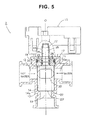
Fig. 5 . A description will be briefly given of a flow rate regulating valve 2 of an illustrated example. - The flow rate regulating valve 2 of the water heater or the like is used in the water heater for obtaining warm water having the desired temperature by mixing water and hot water, has a
cylindrical valve chamber 14 with ceiling portion, is provided withside portion ports valve chamber 14, and is also provided with a valve main body 10' having abottom portion port 13 which is open coaxially with thevalve chamber 14, a valve body 20' which is rotatably installed within thevalve chamber 14 of the valve main body 10' and is rotated around a rotation axis O, and a steppingmotor 15 serving as a driving means for rotating the valve body 20'. - The
side portion ports - The valve body 20' is formed in a cylindrical shape having an opening at a lower end, is structured such that a
peripheral wall portion 22 thereof serves as a seal surface portion for closing theside portion ports opening portion 30 in a predetermined shape (in this case, an oval shape having semicircles at both ends) in theperipheral wall portion 22 for changing an opening area of theside portion ports Fig. 3 showing thevalve body 20 in accordance with an embodiment). Theopening portion 30 is open at about 180 degree on the basis of a rotation angle of the valve body 20'. - A rotating
shaft 25 is provided in a protruding manner at the center of a top surface of aceiling portion 23 of the valve body 20'. A lower portion of the rotatingshaft 25 is provided with installation grooves constituted by three-stage collar portions 28 for installation of O-rings serration shaft portion 26 for coupling to (a shaft of) a rotor of the stepping motor so as to be integrally rotatable, and aconvex portion 27 having a noncircular cross section (D-cut shape or the like). - On the other hand, an installation hole 10a is provided at an upper portion of the
valve chamber 14 in the valve main body 10', abearing 16 for rotatably supporting theceiling portion 23 of the valve body 20' and a lower portion of the rotating shaft 25 (the portion to which the O-rings motor 15 is attached onto thebearing 16 via an attachingplate 17 by bolts and nuts. In this case, aseal member 19 such as an O-ring or the like is installed between the installation hole 10a and thebearing 16. Further, a lower end of thevalve chamber 14 of the valve main body 10' is provided with avalve body seat 14a for receiving (a lower end surface of) the valve body 20'. - The conventional flow rate regulating valve 2 mentioned above has the following problems to be improved.
- Since the flow rate regulating valve 2 is structured such as to assemble the valve body 20' in the valve main body 10' via the installation hole 10a in a manner of bringing it down from the above, parts (the
bearing 16 and the seal member 19) for plugging the installation hole 10a are necessary for preventing water leakage to an external portion. In addition, since a lot of coupling and fixing positions exist among the valve main body 10', thebearing 16, the attachingplate 17 and themotor 15, the number of parts is increased, and problems are caused in the light of assembling workability, a cost, weight saving and the like. - Further, since the structure is made such as to prevent the valve body 20' from coming off downward by the
seat 14a, an abrasion tends to be caused by slidable contact between the lower end surface of the valve body 20' and thevalve body seat 14a, and there is a problem that abrasion powder generated at that time mixes into the fluid (the warm water). - Further, in the flow rate regulating valve 2, since the valve body 20' is structured such that its position (a position in vertical, right-and-left and back-and-forth directions, a position of a rotating axis) is regulated by two members comprising the valve main body 10' and the
bearing 16, a center axis of the valve main body 10' and a center axis of thebearing 16 tend to be displaced due to an assembling error of thebearing 16 with respect to the valve main body 10' or the like. Accordingly, a displacement and an inclination of in (the rotating axis of) the valve body 20' are caused. As a result, there is a risk that the valve body 20' and the valve main body 10' eccentrically contact with each other and a frictional resistance and an abrasion become large. With regard to such the displacement (ensuring of concentricity), since an influence of theseal member 19 such as the O-ring or the like interposed between theinstallation hole 15 and thebearing 16 is added to the factor mentioned above, a drastic improvement is necessary for ensuring the concentricity. - In addition to the above, since the
seat 14a is necessary, there is a tendency that the valve main body 10' becomes longer at that degree, and there is a problem that a forming metal mold becomes complicated. - The present invention is made by taking the circumstances mentioned above into consideration, and an object of the present invention is to provide a compactly structured flow rate regulating valve, in which reduction of the number of parts, improvement of assembling workability, cost reduction, downsizing, weight saving and the like can be achieved, and frictional resistance and abrasion between a valve body and a valve main body can be reduced as much as possible, so that abrasion powder can be prevented from mixing into fluid.
- In order to achieve the object mentioned above, a flow rate regulating valve in accordance with the present invention basically comprises:
- a valve main body having a cylindrical valve chamber with ceiling portion, at least one side portion port which is open at a peripheral wall portion of the valve chamber, and a bottom portion port which is open coaxially with the valve chamber; and
- a lower end opened cylindrical valve body rotatably installed in the valve chamber, and provided with an opening portion at a peripheral wall portion for changing an opening area of the side portion port in accordance with a rotation,
- The present invention can be applied, for example, to a mixing valve structured such that two side portion ports are provided, a first fluid and a second fluid are introduced to one side portion port and the other respectively, a mixing rate of the first fluid and the second fluid is changed on the basis of a rotating motion of the valve body, and a mixed fluid flows out of a bottom portion port.
- In this case, the first fluid can be hot water, and the second fluid can be water.
- In accordance with another preferable aspect, a large-diameter portion is formed at an upper side than the bearing hole of in the rotating shaft, and the valve body locking device is installed to an outer periphery of the rotating shaft at a position between the large-diameter portion and the bearing hole.
- The valve body locking device is preferably made of one elastic wire rod which is bent approximately in a V-shape or U-shape, and is constructed by a clip which is provided with a pair of pinching piece portions having circular arc shaped portions to be pressure-contacted with and fitted to an outer periphery of the rotating shaft, and a bent spring portion for coupling the pair of the pinching piece portions and energizing them in a returning back direction at a time when they are expanded in a direction to make them apart from each other.
- In accordance with another preferable aspect, a seal member such as an O-ring or the like is installed between the rotating shaft and the bearing hole.
- Since the flow rate regulating valve in accordance with the present invention is structured such that the valve body is assembled in the valve main body by being inserted from the lower side, it becomes unnecessary to use the parts (the bearing, the seal member, the attaching plate and the like) for plugging the installation hole, which have been necessary for preventing a water leakage to an external portion, and it is possible to achieve reduction of number of the parts, improvement of the assembling workability, cost reduction, downsizing, weight saving, and the like.
- Further, since the bearing hole, through which the rotating shaft of the valve body is inserted from the lower side, is formed at the ceiling portion of the valve chamber in the valve main body, and the valve body locking device, which allows the rotation of the valve body but prevents the valve body from coming off downward, is installed at the upper side than the bearing hole of the rotating shaft, the valve body seat, which has been necessary in the prior art, is not necessary. While abrasion powder is generated in the inner portion of the valve main body on the basis of slidable contact between the lower end surface of the valve body and the valve body seat in the prior art, however, in the flow rate regulating valve structured as mentioned above in accordance with the present invention, even if abrasion powder is generated on the basis of slidable contact between the valve body locking device and the valve body or (the ceiling portion top surface of) the valve main body, it occurs outside the valve main body, and the abrasion powder does not mix into the fluid.
- Further, since the valve body is structured such that its position (a position in the vertical, right-and-left and back-and-forth directions, and a position of the rotating axis) is regulated only by the valve main body (one member), the displacement and the inclination of (the rotating axis of) the valve body are hardly caused, in comparison with the case that the position is regulated by two members like as the prior art. As a result, it is possible to effectively reduce the friction resistance and the abrasion between the valve body and the valve main body.
-
-
Fig. 1 is a partly notched front view showing an embodiment of a flow rate regulating valve in accordance with the present invention; -
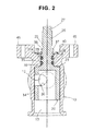
Fig. 2 is a sectional view as seen in a direction shown by arrows X-X except a motor portion in the flow rate regulating valve shown inFig. 1 ; -
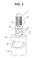
Fig. 3 is a perspective view showing a valve body of the flow rate regulating valve shown inFig. 1 ; -
Figs. 4 (A), 4(B) and 4 (C) are views provided for explaining a clip for serving as a valve body locking device used in the flow rate regulating valve shown inFig. 1 and an attaching method thereof, in whichFig. 4(A) is a plan view of the clip,Fig. 4(B) is a plan view of the flow rate regulating valve during clip attachment, andFig. 4(C) is a plan view of the flow rate regulating valve after finish of the clip attachment; and -
Fig. 5 is a partly notched front view showing a flow rate regulating valve in accordance with a prior art. - A description will be given below of an embodiment of a flow rate regulating valve in accordance with the present invention with reference to the accompanying drawings.
-
Fig. 1 is a partly notched front view showing an embodiment of a flow rate regulating valve in accordance with the present invention,Fig. 2 is a sectional view as seen in a direction shown by arrows X-X except a motor portion inFig. 1 , andFig. 3 is a perspective view of a valve body in accordance with the present embodiment. InFig. 1 , a detailed description is omitted by attaching common reference numerals to portions corresponding to the portions of the flow rate regulating valve 2 shown inFig. 5 mentioned above, and a description will be given below of different points mainly. - A flow rate regulating valve 1 in accordance with the present embodiment is a mixing valve for obtaining warm water having a desired temperature by regulating a mixing rate of water and hot water, has a valve
main body 10, avalve body 20 and astepping motor 15, and is structured such that thevalve body 20 is assembled in the valvemain body 10 by being inserted from a lower side. The valvemain body 10 is provided with acylindrical valve chamber 14 with a comparativelythick ceiling portion 35,side portion ports valve chamber 14 so as to be spaced at an angular interval of 180 degrees, and abottom portion port 13 which is open coaxially with thevalve chamber 14. - Further, attaching
pedestals motor 15 to the valvemain body 10 are provided at positions which are rotated at 90 degrees with respect to theside portion ports main body 10, in such a manner as to protrude upward and right and left sides, as shown inFigs. 2 ,4B and 4C . - The
valve body 20 is formed in a cylindrical shape with an opened lower end, is installed rotatably in thevalve chamber 14 of the valvemain body 10, and is structured such that itsceiling portion 23 is brought into contact with a lower surface of theceiling portion 35 of the valvemain body 10, as shown inFig. 3 . Aperipheral wall portion 22 of thevalve body 20 is provided with anopening portion 30 in a predetermined shape (in this case, an oval shapes with semicircles at both ends), for changing opening areas of theside portion port 11 and theside portion port 12 in accordance with a rotation. Theopening portion 30 is opened at about 180 degrees in a rotational angle of thevalve body 20. - A rotating
shaft 25 is provided to protrude above theceiling portion 23 of thevalve body 20, and abearing hole 36 through which the rotatingshaft 25 of thevalve body 20 is inserted from a lower side is formed in theceiling portion 35 of the valvemain body 10. A lower portion of the rotatingshaft 25 is provided with installation grooves constructed by three-stage collar portions 28 for installation of O-rings serration shaft portion 26 for coupling to (a shaft of) a rotor of a stepping motor so as to be integrally rotatable, and aconvex portion 27 having a noncircular cross section (a D-cut shape or the like). - In addition, a large-
diameter portion 37 having the same diameter as thecollar portions 28 is formed at a position between a lower end of theserration shaft portion 26 and the highest stage collar portion 28 (slightly above an upper end surface of the bearing hole 36) in the rotatingshaft 25, and aclip 40 for serving as a valve body locking device, which allows rotation of thevalve body 20 but prevents thevalve body 20 from coming off downward, is installed to an outer periphery of a position (an installation portion 38) between the large-diameter portion 37 and the higheststage collar portion 28. - The
clip 40 is made of one elastic wire rod which is bent approximately in a V-shape or U-shape, and is constructed by a pair ofpinching piece portions end guide portions 41a which are open outward, circular arc shapedportions 41b which are pressure-contacted with and fitted to an outer periphery of theinstallation portion 38 of the rotatingshaft 25, and abent spring portion 42 for coupling a pair of thepinching piece portions Fig. 4A . Since theclip 40 as mentioned above is available as a general purpose product, it is possible to make a part cost inexpensive. - After the rotating
shaft 25 of thevalve body 20 is inserted into thebearing hole 36 from a lower side, theclip 40 is pressed to theinstallation portion 38 of the rotatingshaft 25 from theside portion port 11 side until the circular arc shapedportions end guide portions installation portion 38 as shown inFig. 4B , and thereafter rotated at 90 degree in a counterclockwise direction as shown inFig. 4C . Accordingly, theclip 40 is mounted onto atop surface 35a of theceiling portion 35, and the whole of thevalve body 20 is locked by theclip 40 in a state of allowing the rotation but preventing the downward coming-off, with the large-diameter portion 37. - As mentioned above, since the flow rate regulating valve 1 in accordance with the present embodiment is structured such that the
valve body 20 is assembled in the valvemain body 10 by inserting thevalve body 20 to the valvemain body 10 from the lower side by using theclip 40, it becomes unnecessary to use the parts (thebearing 16, theseal member 19, the attachingplate 17 and the like) for plugging the installation hole which have been necessary in the prior art for preventing a water leakage to an external portion, and it is possible to achieve reduction of the number of parts, improvement of the assembling workability, cost reduction, downsizing, weight saving, and the like. - Further, since the bearing
hole 36, through which therotating shaft 25 of thevalve body 20 is inserted from the lower side, is formed at theceiling portion 35 of thevalve chamber 14 in the valvemain body 10, and theclip 40, which allows the rotation of thevalve body 20 but prevents thevalve body 20 from coming off downward, is installed at the upper side than the bearinghole 36 of therotating shaft 25, thevalve body seat 14a, which is necessary in the prior art, becomes unnecessary. While the abrasion powder is generated in the inner portion of the valvemain body 10 by slidable contact between the lower end surface of thevalve body 20 and thevalve body seat 14a in the prior art, however, in the flow rate regulating valve 1 in accordance with the present embodiment as mentioned above, even if the abrasion powder is generated by the slidable contact between theclip 40 and the valve body 20 (or thetop surface 35a of theceiling portion 35 of the valve main body 10), the abrasion powder do not mix into the warm water because it occurs outside the valvemain body 10. - Further, since the
valve body 20 is structured such that its position (a position in the vertical, right-and-left and back-and-forth directions and a position of the rotating axis) is regulated only by the valve main body 10 (one member), the displacement and the inclination of (the rotating axis O of) thevalve body 20 are hardly caused in comparison with the case that the position is regulated by two members like as the prior at. As a result, it is possible to effectively reduce the frictional resistance and the abrasion between thevalve body 20 and the valvemain body 10. - In this case, in the embodiment mentioned above, the valve
main body 10 and thevalve body 20 are made of a synthetic resin (for example, POM, PPS or the like), however, they may be made of a metal. In general, the synthetic resin structure is superior to the metal structure in a sliding performance. - Further, in the embodiment mentioned above, the description is given of the case that the present invention is applied to the flow rate regulating valve structured such that warm water having a desired temperature is obtained by regulating the mixing rate of hot water and water, however, the present invention can be applied to a flow rate regulating valve for mixing plural kinds of other fluids than water and hot water.
- Further, in the embodiment mentioned above, the description is given of the case that the present invention is applied to the angle valve which is provided with two side portion ports in the peripheral wall portion of the valve chamber, and is provided with the bottom portion port which is open coaxially with the valve chamber, however, the present invention can be applied to an angle valve which is provided with one side portion port in the peripheral wall portion of the valve chamber, and is provided with the bottom port which is open coaxially with the valve chamber.
- In addition, the embodiment can be variously modified within the scope of the present invention.
Claims (6)
- A flow rate regulating valve comprising:a valve main body having a cylindrical valve chamber with ceiling portion, at least one side portion port which is open at a peripheral wall portion of said valve chamber, and a bottom portion port which is open coaxially with said valve chamber; anda lower end opened cylindrical valve body rotatably installed in said valve chamber, and provided with an opening portion in a peripheral wall portion for changing an opening area of said side portion port in accordance with a rotation,wherein said valve body is installed from said bottom portion port, a rotating shaft provided in a protruding manner at a ceiling portion of said valve body protrudes from a bearing hole of said valve main body in this installed state, and
wherein a valve body locking device which allows rotation of said valve body but prevents the valve body from coming off downward, is installed at a protruded portion of said rotating shaft from said valve main body. - A flow rate regulating valve as claimed in claim 1, wherein two of said side portion ports are provided, first fluid and second fluid are introduced to one side portion port and the other respectively, a mixing rate of the first fluid and the second fluid is changed on the basis of a rotating motion of said valve body, and mixed fluid flows out of said bottom portion port.
- A flow rate regulating valve as claimed in claim 2, wherein said first fluid is hot water, and said second fluid is water.
- A flow rate regulating valve as claimed in any one of claims 1 to 3, wherein a large-diameter portion is formed at an upper side than said bearing hole of said rotating shaft, and said valve body locking device is installed to an outer periphery of said rotating shaft at a position between said large-diameter portion and said bearing hole.
- A flow rate regulating valve as claimed in any one of claims 1 to 4, wherein said valve body locking device is made of one elastic wire rod which is bent approximately in a V-shape or U-shape, and is constructed by a clip which is provided with a pair of pinching piece portions having circular arc shaped portions to be pressure contacted with and fitted to an outer periphery of said rotating shaft, and a bent spring portion for coupling said pair of pinching piece portions and energizing them in a returning back direction at a time when they are expanded in a direction to make them apart from each other.
- A flow rate regulating valve as claimed in any one of claims 1 to 5, wherein a seal member such as an O-ring or the like is installed between said rotating shaft and said bearing hole.
Applications Claiming Priority (1)
| Application Number | Priority Date | Filing Date | Title |
|---|---|---|---|
| JP2008074179A JP2009228764A (en) | 2008-03-21 | 2008-03-21 | Flow regulating valve |
Publications (2)
| Publication Number | Publication Date |
|---|---|
| EP2103852A2 true EP2103852A2 (en) | 2009-09-23 |
| EP2103852A3 EP2103852A3 (en) | 2009-11-04 |
Family
ID=40724726
Family Applications (1)
| Application Number | Title | Priority Date | Filing Date |
|---|---|---|---|
| EP09155555A Withdrawn EP2103852A3 (en) | 2008-03-21 | 2009-03-19 | Flow rate regulating valve |
Country Status (4)
| Country | Link |
|---|---|
| EP (1) | EP2103852A3 (en) |
| JP (1) | JP2009228764A (en) |
| KR (1) | KR20090101070A (en) |
| CN (1) | CN101539213A (en) |
Cited By (5)
| Publication number | Priority date | Publication date | Assignee | Title |
|---|---|---|---|---|
| EP2189692A3 (en) * | 2008-11-21 | 2010-06-09 | Symyx Solutions Inc. | Dispensing valve |
| WO2011058249A1 (en) * | 2009-11-16 | 2011-05-19 | Arkling Limited | Valve having a rotatable stopper, and water treatment facility comprising such a valve |
| CN103161974A (en) * | 2011-12-12 | 2013-06-19 | 上海倍夫克阀门有限公司 | Three-way ball valve |
| US11112014B2 (en) | 2016-11-22 | 2021-09-07 | Shinwa Controls Co., Ltd. | Two-way valve for flow rate control and temperature control device using the same |
| WO2021180097A1 (en) * | 2020-03-09 | 2021-09-16 | 芜湖美的厨卫电器制造有限公司 | Electronic thermostatic valve and water heater having same |
Families Citing this family (7)
| Publication number | Priority date | Publication date | Assignee | Title |
|---|---|---|---|---|
| JP6013026B2 (en) * | 2012-05-18 | 2016-10-25 | 株式会社不二工機 | Rotary valve |
| CN103206557A (en) * | 2013-02-05 | 2013-07-17 | 佛山市南海南宝冷冻食品有限公司 | Water reversing pneumatic valve |
| CN106090296A (en) * | 2016-08-20 | 2016-11-09 | 开平市雅致卫浴有限公司 | A kind of shunt valve body |
| DE102019126775A1 (en) * | 2019-10-04 | 2021-04-08 | Eto Magnetic Gmbh | Rotary slide valve for regulating a fluid flow and method for manufacturing a rotary slide valve |
| CN111102380B (en) * | 2020-02-24 | 2022-05-10 | 长江师范学院 | Method for improving shower comfort |
| JP2023087314A (en) * | 2021-12-13 | 2023-06-23 | 株式会社山田製作所 | control valve |
| CN114871402A (en) * | 2021-12-17 | 2022-08-09 | 刘明 | Novel die casting machine, pressure casting method, and method and device for switching on and off of cavity opening |
Citations (5)
| Publication number | Priority date | Publication date | Assignee | Title |
|---|---|---|---|---|
| DE2101978A1 (en) * | 1971-01-16 | 1972-08-03 | Lang & Menke Gmbh Ing | Circlip made from profile material |
| FR2211097A5 (en) * | 1972-12-15 | 1974-07-12 | Ouest Produits Indls | |
| JP2000179715A (en) * | 1998-12-15 | 2000-06-27 | Tgk Co Ltd | Mixing valve |
| WO2004011829A2 (en) * | 2002-07-31 | 2004-02-05 | Brass-Craft Manufacturing Company | Stop valve |
| JP2007032628A (en) * | 2005-07-25 | 2007-02-08 | Mym Corp | Water combination faucet |
-
2008
- 2008-03-21 JP JP2008074179A patent/JP2009228764A/en active Pending
- 2008-12-29 KR KR1020080135134A patent/KR20090101070A/en not_active Application Discontinuation
-
2009
- 2009-03-18 CN CN200910128689A patent/CN101539213A/en active Pending
- 2009-03-19 EP EP09155555A patent/EP2103852A3/en not_active Withdrawn
Patent Citations (5)
| Publication number | Priority date | Publication date | Assignee | Title |
|---|---|---|---|---|
| DE2101978A1 (en) * | 1971-01-16 | 1972-08-03 | Lang & Menke Gmbh Ing | Circlip made from profile material |
| FR2211097A5 (en) * | 1972-12-15 | 1974-07-12 | Ouest Produits Indls | |
| JP2000179715A (en) * | 1998-12-15 | 2000-06-27 | Tgk Co Ltd | Mixing valve |
| WO2004011829A2 (en) * | 2002-07-31 | 2004-02-05 | Brass-Craft Manufacturing Company | Stop valve |
| JP2007032628A (en) * | 2005-07-25 | 2007-02-08 | Mym Corp | Water combination faucet |
Cited By (7)
| Publication number | Priority date | Publication date | Assignee | Title |
|---|---|---|---|---|
| EP2189692A3 (en) * | 2008-11-21 | 2010-06-09 | Symyx Solutions Inc. | Dispensing valve |
| WO2011058249A1 (en) * | 2009-11-16 | 2011-05-19 | Arkling Limited | Valve having a rotatable stopper, and water treatment facility comprising such a valve |
| FR2952691A1 (en) * | 2009-11-16 | 2011-05-20 | Laurence Technologies Sa | ROTARY SHUTTER VALVE AND WATER TREATMENT PLANT COMPRISING SUCH VALVE |
| US9371922B2 (en) | 2009-11-16 | 2016-06-21 | Arkling Limited | Valve having a rotatable stopper, and water treatment plant comprising such a valve |
| CN103161974A (en) * | 2011-12-12 | 2013-06-19 | 上海倍夫克阀门有限公司 | Three-way ball valve |
| US11112014B2 (en) | 2016-11-22 | 2021-09-07 | Shinwa Controls Co., Ltd. | Two-way valve for flow rate control and temperature control device using the same |
| WO2021180097A1 (en) * | 2020-03-09 | 2021-09-16 | 芜湖美的厨卫电器制造有限公司 | Electronic thermostatic valve and water heater having same |
Also Published As
| Publication number | Publication date |
|---|---|
| KR20090101070A (en) | 2009-09-24 |
| EP2103852A3 (en) | 2009-11-04 |
| JP2009228764A (en) | 2009-10-08 |
| CN101539213A (en) | 2009-09-23 |
Similar Documents
| Publication | Publication Date | Title |
|---|---|---|
| EP2103852A2 (en) | Flow rate regulating valve | |
| US9803759B2 (en) | Disc valve | |
| CA2487631C (en) | Two-handle flow-through valve | |
| CN100590336C (en) | Improvements in mixing valves | |
| EP1589268B1 (en) | Water mixing valve | |
| US7905424B2 (en) | Thermostatic mixing valve | |
| JPH0652104B2 (en) | Reversible bottom valve cartridge with orientation determination mechanism | |
| US8082951B2 (en) | Diverter valve apparatus and method | |
| US9441750B2 (en) | Valve cartridge | |
| EP3557163B1 (en) | Refrigerator door body and refrigerator provided with same | |
| CN109944309A (en) | Closestool connector | |
| US20170168510A1 (en) | Fluid mixing valve | |
| EP1703026A2 (en) | A fluid distribution device | |
| US7093821B2 (en) | Fluid flow control valve | |
| US20090242051A1 (en) | Internal assembly for a faucet | |
| JP5004675B2 (en) | Mixing valve | |
| JP2010001925A (en) | Flow regulating valve | |
| JP6073103B2 (en) | Double-mixing valve device | |
| JP5004674B2 (en) | Mixing valve | |
| CN106917882B (en) | Faucet with offset valve | |
| JP5004673B2 (en) | Mixing valve | |
| JP6073102B2 (en) | Double-mixing valve device | |
| CN210978579U (en) | Integrated rotary valve core and kitchen faucet with same | |
| JP7116486B2 (en) | control valve | |
| CN211202985U (en) | Shower faucet convenient to assemble |
Legal Events
| Date | Code | Title | Description |
|---|---|---|---|
| PUAI | Public reference made under article 153(3) epc to a published international application that has entered the european phase |
Free format text: ORIGINAL CODE: 0009012 |
|
| AK | Designated contracting states |
Kind code of ref document: A2 Designated state(s): AT BE BG CH CY CZ DE DK EE ES FI FR GB GR HR HU IE IS IT LI LT LU LV MC MK MT NL NO PL PT RO SE SI SK TR |
|
| AX | Request for extension of the european patent |
Extension state: AL BA RS |
|
| PUAL | Search report despatched |
Free format text: ORIGINAL CODE: 0009013 |
|
| AK | Designated contracting states |
Kind code of ref document: A3 Designated state(s): AT BE BG CH CY CZ DE DK EE ES FI FR GB GR HR HU IE IS IT LI LT LU LV MC MK MT NL NO PL PT RO SE SI SK TR |
|
| AX | Request for extension of the european patent |
Extension state: AL BA RS |
|
| 17P | Request for examination filed |
Effective date: 20100219 |
|
| 17Q | First examination report despatched |
Effective date: 20100317 |
|
| AKX | Designation fees paid |
Designated state(s): DE FR GB IT |
|
| STAA | Information on the status of an ep patent application or granted ep patent |
Free format text: STATUS: THE APPLICATION IS DEEMED TO BE WITHDRAWN |
|
| 18D | Application deemed to be withdrawn |
Effective date: 20100728 |