EP2103797A2 - Fuel injection pressure control method in liquefied fuel engine - Google Patents
Fuel injection pressure control method in liquefied fuel engine Download PDFInfo
- Publication number
- EP2103797A2 EP2103797A2 EP09250348A EP09250348A EP2103797A2 EP 2103797 A2 EP2103797 A2 EP 2103797A2 EP 09250348 A EP09250348 A EP 09250348A EP 09250348 A EP09250348 A EP 09250348A EP 2103797 A2 EP2103797 A2 EP 2103797A2
- Authority
- EP
- European Patent Office
- Prior art keywords
- fuel
- fuel injection
- injection pressure
- engine
- pressure
- Prior art date
- Legal status (The legal status is an assumption and is not a legal conclusion. Google has not performed a legal analysis and makes no representation as to the accuracy of the status listed.)
- Withdrawn
Links
- 239000000446 fuel Substances 0.000 title claims abstract description 195
- 238000002347 injection Methods 0.000 title claims abstract description 84
- 239000007924 injection Substances 0.000 title claims abstract description 84
- 238000000034 method Methods 0.000 title claims abstract description 16
- 239000002828 fuel tank Substances 0.000 claims abstract description 14
- 238000005259 measurement Methods 0.000 claims abstract description 4
- 230000014509 gene expression Effects 0.000 claims description 6
- 238000004088 simulation Methods 0.000 claims description 4
- 239000007788 liquid Substances 0.000 description 6
- 239000007789 gas Substances 0.000 description 5
- 230000006866 deterioration Effects 0.000 description 3
- 238000001514 detection method Methods 0.000 description 2
- 230000000694 effects Effects 0.000 description 2
- 239000003502 gasoline Substances 0.000 description 2
- 238000012423 maintenance Methods 0.000 description 2
- 238000004519 manufacturing process Methods 0.000 description 2
- MYMOFIZGZYHOMD-UHFFFAOYSA-N Dioxygen Chemical compound O=O MYMOFIZGZYHOMD-UHFFFAOYSA-N 0.000 description 1
- 230000002411 adverse Effects 0.000 description 1
- 238000004364 calculation method Methods 0.000 description 1
- 230000002542 deteriorative effect Effects 0.000 description 1
- 229910001882 dioxygen Inorganic materials 0.000 description 1
- 230000007613 environmental effect Effects 0.000 description 1
- 230000008016 vaporization Effects 0.000 description 1
- 238000009834 vaporization Methods 0.000 description 1
Images

Classifications
-
- F—MECHANICAL ENGINEERING; LIGHTING; HEATING; WEAPONS; BLASTING
- F02—COMBUSTION ENGINES; HOT-GAS OR COMBUSTION-PRODUCT ENGINE PLANTS
- F02D—CONTROLLING COMBUSTION ENGINES
- F02D19/00—Controlling engines characterised by their use of non-liquid fuels, pluralities of fuels, or non-fuel substances added to the combustible mixtures
- F02D19/02—Controlling engines characterised by their use of non-liquid fuels, pluralities of fuels, or non-fuel substances added to the combustible mixtures peculiar to engines working with gaseous fuels
- F02D19/021—Control of components of the fuel supply system
- F02D19/022—Control of components of the fuel supply system to adjust the fuel pressure, temperature or composition
-
- F—MECHANICAL ENGINEERING; LIGHTING; HEATING; WEAPONS; BLASTING
- F02—COMBUSTION ENGINES; HOT-GAS OR COMBUSTION-PRODUCT ENGINE PLANTS
- F02D—CONTROLLING COMBUSTION ENGINES
- F02D19/00—Controlling engines characterised by their use of non-liquid fuels, pluralities of fuels, or non-fuel substances added to the combustible mixtures
- F02D19/02—Controlling engines characterised by their use of non-liquid fuels, pluralities of fuels, or non-fuel substances added to the combustible mixtures peculiar to engines working with gaseous fuels
-
- F—MECHANICAL ENGINEERING; LIGHTING; HEATING; WEAPONS; BLASTING
- F02—COMBUSTION ENGINES; HOT-GAS OR COMBUSTION-PRODUCT ENGINE PLANTS
- F02D—CONTROLLING COMBUSTION ENGINES
- F02D19/00—Controlling engines characterised by their use of non-liquid fuels, pluralities of fuels, or non-fuel substances added to the combustible mixtures
- F02D19/02—Controlling engines characterised by their use of non-liquid fuels, pluralities of fuels, or non-fuel substances added to the combustible mixtures peculiar to engines working with gaseous fuels
- F02D19/026—Measuring or estimating parameters related to the fuel supply system
- F02D19/027—Determining the fuel pressure, temperature or volume flow, the fuel tank fill level or a valve position
- F02D19/028—Determining the fuel pressure, temperature or volume flow, the fuel tank fill level or a valve position by estimation, i.e. without using direct measured parameter of a corresponding sensor
-
- F—MECHANICAL ENGINEERING; LIGHTING; HEATING; WEAPONS; BLASTING
- F02—COMBUSTION ENGINES; HOT-GAS OR COMBUSTION-PRODUCT ENGINE PLANTS
- F02D—CONTROLLING COMBUSTION ENGINES
- F02D41/00—Electrical control of supply of combustible mixture or its constituents
- F02D41/02—Circuit arrangements for generating control signals
-
- F—MECHANICAL ENGINEERING; LIGHTING; HEATING; WEAPONS; BLASTING
- F02—COMBUSTION ENGINES; HOT-GAS OR COMBUSTION-PRODUCT ENGINE PLANTS
- F02D—CONTROLLING COMBUSTION ENGINES
- F02D41/00—Electrical control of supply of combustible mixture or its constituents
- F02D41/02—Circuit arrangements for generating control signals
- F02D41/04—Introducing corrections for particular operating conditions
-
- F—MECHANICAL ENGINEERING; LIGHTING; HEATING; WEAPONS; BLASTING
- F02—COMBUSTION ENGINES; HOT-GAS OR COMBUSTION-PRODUCT ENGINE PLANTS
- F02M—SUPPLYING COMBUSTION ENGINES IN GENERAL WITH COMBUSTIBLE MIXTURES OR CONSTITUENTS THEREOF
- F02M21/00—Apparatus for supplying engines with non-liquid fuels, e.g. gaseous fuels stored in liquid form
- F02M21/02—Apparatus for supplying engines with non-liquid fuels, e.g. gaseous fuels stored in liquid form for gaseous fuels
-
- F—MECHANICAL ENGINEERING; LIGHTING; HEATING; WEAPONS; BLASTING
- F02—COMBUSTION ENGINES; HOT-GAS OR COMBUSTION-PRODUCT ENGINE PLANTS
- F02M—SUPPLYING COMBUSTION ENGINES IN GENERAL WITH COMBUSTIBLE MIXTURES OR CONSTITUENTS THEREOF
- F02M21/00—Apparatus for supplying engines with non-liquid fuels, e.g. gaseous fuels stored in liquid form
- F02M21/02—Apparatus for supplying engines with non-liquid fuels, e.g. gaseous fuels stored in liquid form for gaseous fuels
- F02M21/0203—Apparatus for supplying engines with non-liquid fuels, e.g. gaseous fuels stored in liquid form for gaseous fuels characterised by the type of gaseous fuel
- F02M21/0209—Hydrocarbon fuels, e.g. methane or acetylene
- F02M21/0212—Hydrocarbon fuels, e.g. methane or acetylene comprising at least 3 C-Atoms, e.g. liquefied petroleum gas [LPG], propane or butane
-
- F—MECHANICAL ENGINEERING; LIGHTING; HEATING; WEAPONS; BLASTING
- F02—COMBUSTION ENGINES; HOT-GAS OR COMBUSTION-PRODUCT ENGINE PLANTS
- F02M—SUPPLYING COMBUSTION ENGINES IN GENERAL WITH COMBUSTIBLE MIXTURES OR CONSTITUENTS THEREOF
- F02M21/00—Apparatus for supplying engines with non-liquid fuels, e.g. gaseous fuels stored in liquid form
- F02M21/02—Apparatus for supplying engines with non-liquid fuels, e.g. gaseous fuels stored in liquid form for gaseous fuels
- F02M21/0218—Details on the gaseous fuel supply system, e.g. tanks, valves, pipes, pumps, rails, injectors or mixers
- F02M21/0287—Details on the gaseous fuel supply system, e.g. tanks, valves, pipes, pumps, rails, injectors or mixers characterised by the transition from liquid to gaseous phase ; Injection in liquid phase; Cooling and low temperature storage
-
- F—MECHANICAL ENGINEERING; LIGHTING; HEATING; WEAPONS; BLASTING
- F02—COMBUSTION ENGINES; HOT-GAS OR COMBUSTION-PRODUCT ENGINE PLANTS
- F02D—CONTROLLING COMBUSTION ENGINES
- F02D19/00—Controlling engines characterised by their use of non-liquid fuels, pluralities of fuels, or non-fuel substances added to the combustible mixtures
- F02D19/02—Controlling engines characterised by their use of non-liquid fuels, pluralities of fuels, or non-fuel substances added to the combustible mixtures peculiar to engines working with gaseous fuels
- F02D19/021—Control of components of the fuel supply system
- F02D19/023—Control of components of the fuel supply system to adjust the fuel mass or volume flow
- F02D19/024—Control of components of the fuel supply system to adjust the fuel mass or volume flow by controlling fuel injectors
-
- F—MECHANICAL ENGINEERING; LIGHTING; HEATING; WEAPONS; BLASTING
- F02—COMBUSTION ENGINES; HOT-GAS OR COMBUSTION-PRODUCT ENGINE PLANTS
- F02M—SUPPLYING COMBUSTION ENGINES IN GENERAL WITH COMBUSTIBLE MIXTURES OR CONSTITUENTS THEREOF
- F02M21/00—Apparatus for supplying engines with non-liquid fuels, e.g. gaseous fuels stored in liquid form
- F02M21/02—Apparatus for supplying engines with non-liquid fuels, e.g. gaseous fuels stored in liquid form for gaseous fuels
- F02M21/0218—Details on the gaseous fuel supply system, e.g. tanks, valves, pipes, pumps, rails, injectors or mixers
- F02M21/0245—High pressure fuel supply systems; Rails; Pumps; Arrangement of valves
-
- Y—GENERAL TAGGING OF NEW TECHNOLOGICAL DEVELOPMENTS; GENERAL TAGGING OF CROSS-SECTIONAL TECHNOLOGIES SPANNING OVER SEVERAL SECTIONS OF THE IPC; TECHNICAL SUBJECTS COVERED BY FORMER USPC CROSS-REFERENCE ART COLLECTIONS [XRACs] AND DIGESTS
- Y02—TECHNOLOGIES OR APPLICATIONS FOR MITIGATION OR ADAPTATION AGAINST CLIMATE CHANGE
- Y02T—CLIMATE CHANGE MITIGATION TECHNOLOGIES RELATED TO TRANSPORTATION
- Y02T10/00—Road transport of goods or passengers
- Y02T10/10—Internal combustion engine [ICE] based vehicles
- Y02T10/30—Use of alternative fuels, e.g. biofuels
Definitions
- the invention provided a variable target fuel injection pressure control method in a liquefied fuel engine including a fuel supply pipe extending from a fuel tank and having an injector on the distal side thereof, a fuel pump disposed in the fuel supply pipe, and an electronic control unit which controls driving of the injector and the fuel pump, and which pressurizes a liquefied gas fuel stored in the fuel tank by a fuel pump to feed the gas fuel to the injector via the fuel supply pipe and supply the gas fuel to the engine.
- system parameters on operating states which cannot be actually measured are estimated using Formula (1) showing the numerical formula model
- simulation is performed on the basis of the numerical formula model to determine optimal control parameters
- a fuel injection pressure required according to a fuel injection amount required by the engine 1 which is obtained from the engine rotation number and the intake air pressure in the electronic control unit 10 provided in the fuel supply device is determined using the determined control parameters
- the pump delivery pressure of the fuel pump 3 is controlled in real time such that the fuel injection pressure becomes a target pressure in all operation conditions.
Landscapes
- Engineering & Computer Science (AREA)
- Chemical & Material Sciences (AREA)
- Combustion & Propulsion (AREA)
- Mechanical Engineering (AREA)
- General Engineering & Computer Science (AREA)
- Chemical Kinetics & Catalysis (AREA)
- General Chemical & Material Sciences (AREA)
- Oil, Petroleum & Natural Gas (AREA)
- Electrical Control Of Air Or Fuel Supplied To Internal-Combustion Engine (AREA)
- Output Control And Ontrol Of Special Type Engine (AREA)
Abstract
Description
- The present invention relates to a fuel injection pressure control method in a liquefied fuel engine which forcibly feeds a liquid fuel, which is apt to vaporize compared with gasoline, like LPG or DME, from a fuel tank to an injector in a liquid state, and injects and supplies the liquid fuel to the engine.
- A fuel injection control type engine system which measures and injects a liquid fuel, which vaporizes more easily than gasoline, like LPG or DME by an injector, and supplies the liquid fuel to an engine in a liquid state is well known. This system is mounted on an automobile, etc. In recent years, requests for environmental measures, low fuel consumption, low exhaust gas, energy saving, etc. are strong, and especially, a fuel injection control has a great influence on engine control performance and exhaust air. Therefore, energy saving, high speed, high precision, etc. are desired strongly.
- Meanwhile, in the conventional fuel injection control type engine system, in order to be able to cope with all operation conditions, the fuel injection pressure is always controlled at constant high pressure irrespective of the magnitude of the fuel injection amount. Therefore, in an engine load state where the injection amount from an injector is extremely large, the number of rotations of a fuel pump driving motor becomes high, and the load of the motor increases, and a large electric current flows into the motor. As a result, fuel is consumed too much. Additionally, since a large electric current flows into the fuel pump driving motor over a long time, there is a problem in that the temperature of the motor or motor driver rises, and durability deteriorates.
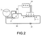
- Thus, as shown in
FIG. 2 , a return type fuel supply system is known in which a constant amount of liquefied gas fuel stored in afuel tank 2 is forcibly fed to a fuel supply pipe 9 by an electrically-operatedfuel pump 3 driven by a DC motor or the like, the fuel is supplied at a flow rated required by an engine from aninjector 8 via the fuel supply pipe 9 after pressure is constantly adjusted by arelief valve 40, and an surplus fuel is returned to thefuel tank 2 via apressure regulator 41 by afuel return pipe 9C. - In such a conventional fuel supply system, in order to be able to cope with all engine operation conditions, the discharge flow rate of the electrically-operated
fuel pump 3 is set to be greater than or equal to a maximum injection amount of fuel ejected from theinjector 8. However, since delivered fuel returns to thefuel tank 2 from thepressure regulator 41, for example, in a situation where the fuel injection amount from theinjectors 8 is extremely small during idling, fuel cut, etc., the energy given to the electrically-operatedfuel pump 3 will be consumed wastefully. Additionally, when a surplus fuel whose temperature has become high through the vicinity of theengine 1 is returned to thefuel tank 2 in large quantities, the fuel temperature within the tank will be raised, fuel vapor will be generated, and the discharge amount of the pump will become unstable, which exerts an adverse effect on exhaust air. - Thus, as described in Japanese Patent Application Laid-Open Nos.
7-54725 2001-234829 2003-232234 - The invention is intended to solve the above problems, and an object of the invention is to provide a fuel injection pressure control method in a liquefied fuel engine including an injector extending from a fuel tank and annexed to the engine on the distal side of a fuel supply pipe, a fuel pump disposed in the fuel supply pipe, and an electronic control unit which controls driving of the fuel pump driving motor and the injector, and which controls a required fuel injection pressure according to a fuel injection amount corresponding to all operation conditions, thereby preventing deterioration of fuel consumption caused by an increase in load in the motor by wasteful high rotation of the fuel pump driving motor that is a conventional problem in control at high pressure or a rise in temperature in the motor or motor driver to improve durability.
- In order to achieve the above object, the invention provided a variable target fuel injection pressure control method in a liquefied fuel engine including a fuel supply pipe extending from a fuel tank and having an injector on the distal side thereof, a fuel pump disposed in the fuel supply pipe, and an electronic control unit which controls driving of the injector and the fuel pump, and which pressurizes a liquefied gas fuel stored in the fuel tank by a fuel pump to feed the gas fuel to the injector via the fuel supply pipe and supply the gas fuel to the engine. Here, the method includes creating a numerical formula model showing a physical relationship of the fuel supply device obtained from values of an engine rotation number and an intake air pressure that are actual measurement values by various sensors annexed to the fuel supply device, estimating system parameters on operating states which cannot be actually measured, by using the created numerical formula model, performing simulation on the basis of the numerical formula model to determine optimal control parameters, and determining a fuel injection pressure required according to a fuel injection amount required by the engine which is obtained in the electronic control unit provided in the fuel supply device by using the determined control parameters.
- It is possible to control the fuel injection pressure such that the fuel injection pressure becomes a target pressure in all operation conditions. Hence, when fuel injection amount is extremely small, fuel is apt to vaporize. Thus, when the fuel injection pressure is set high, and the fuel injection amount is large, the fuel is not susceptible to vaporization. Thus, it is possible to perform a theoretical control that it is not necessary to set the fuel injection to a high value. Hence, the power consumption of a pump driving electric motor which drives a fuel pump is suppressed, and the durability of the pump driving motor and motor driver is improved.
- Additionally, a probability that the fuel injection pressure changes and operational characteristics of the injector, etc. exert a bad effect on exhaust air is eliminated by correcting the fuel injection time according to the fuel injection pressure.
- In addition, the following relational expression (1) determined by an engine rotation number and an intake air pressure is included in the numerical formula model for obtaining a target fuel injection pressure in the invention.

- Further, in the invention, the following relational expressions (2) and (3) are used when correction of a fuel injection time is performed automatically according to the target fuel injection pressure.


- According to the invention, it is possible to lower manufacture price or maintenance cost without necessitating a complicated configuration including a return type or a plurality of fuel systems. Particularly by controlling a required fuel injection pressure according to a fuel injection amount in all operation conditions, it is possible to prevent deterioration of fuel consumption caused by an increase in load in the motor by wasteful high rotation of a fuel pump driving motor or a rise in temperature in the motor or motor driver to improve durability, and it is possible to obtain good exhaust air.
-
-
FIG. 1 is a layout drawing illustrating a liquefied fuel engine for carrying out an embodiment of the invention. -
FIG. 2 is a layout drawing illustrating a conventional example. - Hereinafter, best modes for carrying out the invention will be described in detail.
-
FIG. 1 illustrates a layout drawing of a liquefied fuel engine for carrying out a fuel injection pressure control method according to the present invention. Referring to this drawing, a return-less type fuel supply system is constructed such that afuel pump 3 driven by anelectric motor 3a is disposed near an outlet of afuel delivery pipe 9A which extends from afuel tank 2, a distal side of afuel supply pipe 9B which extends by way of a fuel pressure sensor 11 from thefuel pump 3 is connected to aninjector 8 disposed in anintake pipe 4 of anengine 1, and a fuel return pipe is not provided on the downstream side of theinjector 8. - Additionally, the
electric motor 3a which drives thefuel pump 3, theinjector 8, and anignition plug 7 are electrically connected to an electronic control unit (ECU) 10, respectively, and their respective driving is controlled according to operating states of theengine 1. Moreover, the fuel pressure sensor 11 which detects fuel pressure is arranged before theinjector 8 in thefuel supply pipe 9B on the downstream side of thefuel pump 3, and acrank angle sensor 13 which detects an engine rotation number is arranged in theengine 1. Detection signals outputted from these sensors, respectively, are sent to theelectronic control unit 10. Then, theelectronic control unit 10 determines a fuel injection pressure required according to a fuel injection amount required by the engine, and controls theelectric motor 3a, theinjector 8, theignition plug 7, etc. - In addition,
reference numeral 12 inFIG. 1 represents an intake pressure sensor arranged in theintake pipe 4,reference numeral 14 represents an opening and closing valve arranged in theintake pipe 4, andreference numeral 16 represents an oxygen gas sensor arranged in anexhaust pipe 15. - In order to perform a fuel injection pressure control according to this embodiment, first, the
engine 1 that is the present embodiment is started, and a numerical formula model showing a physical relationship of a fuel supply device obtained from a plurality of kinds of data, such as an intake air pressure within theintake pipe 4 from theintake pressure sensor 12 arranged in theintake pipe 4, and an engine rotation number from thecrank angle sensor 13 is created. - The following relational expression (1) shows a numerical formula model showing a physical relationship.

- Next, in the
electronic control unit 10, system parameters on operating states which cannot be actually measured are estimated using Formula (1) showing the numerical formula model, simulation is performed on the basis of the numerical formula model to determine optimal control parameters, a fuel injection pressure required according to a fuel injection amount required by theengine 1 which is obtained from the engine rotation number and the intake air pressure in theelectronic control unit 10 provided in the fuel supply device is determined using the determined control parameters, and the pump delivery pressure of thefuel pump 3 is controlled in real time such that the fuel injection pressure becomes a target pressure in all operation conditions. - Specifically, in the present embodiment, the
electronic control unit 10 feeds back a detection signal of the fuel pressure sensor 11 arranged just before theinjector 8, which is considered to an actual fuel injection pressure, and when a fuel injection time is connected automatically according to the target fuel injection pressure, a microcomputer of theelectronic control unit 10 performs calculation of a fuel injection amount correction time and final fuel injection time by using the following relational expressions (2) and (3), and corrects the fuel injection time such that the actual fuel injection pressure coincides with the target fuel injection pressure. Hence, an exhaust state caused by a change in fuel injection pressure can be prevented from deteriorating.

- As descried above, application of the conventional return type mechanical control was difficult in a fuel supply system in which a target fuel injection pressure changes depending on a fuel temperature, a fuel injection flow rate, etc. Thus, according to this embodiment, there is introduced a variable target fuel injection pressure control method of creating a numerical formula model showing a physical relationship of a fuel supply device obtained from a plurality of actual measurement values by various sensors annexed to the fuel supply device, estimating system parameters on operating states which cannot be actually measured, by using the created numerical formula model, performing simulation on the basis of the numerical formula model to determine optimal control parameters, and determining a fuel injection pressure required according to a fuel injection amount required by the engine which is obtained in an electronic control unit provided in the fuel supply device by using the determined control parameters. Hence, it becomes unnecessary to always set the fuel injection pressure to a high pressure like the conventional system, deterioration of the fuel pump can be prevented, and exhaust air is also improved.
Claims (4)
- A fuel injection pressure control method in a liquefied fuel engine including a fuel supply pipe extending from a fuel tank and having an injector on the distal side thereof, a fuel pump disposed in the fuel supply pipe, and an electronic control unit which controls driving of the injector and the fuel pump, and which pressurizes a liquefied gas fuel stored in the fuel tank by a fuel pump to feed the gas fuel to the injector via the fuel supply pipe and supply the gas fuel to the engine,the method comprising:creating a numerical formula model showing a physical relationship of the fuel supply device obtained from values of an engine rotation number and an intake air pressure that are actual measurement values by various sensors annexed to the fuel supply device,estimating system parameters on operating states which cannot be actually measured, by using the created numerical formula model,performing simulation on the basis of the numerical formula model to determine optimal control parameters, anddetermining a fuel injection pressure required according to a fuel injection amount required by the engine which is obtained in an electronic control unit provided in the fuel supply device by using the determined control parameters.
- The fuel injection pressure control method in a liquefied fuel engine according to Claim 1,
wherein the following relational expression (1) is included in the numerical formula model.
- The fuel injection pressure control method in a liquefied fuel engine according to Claim 1 or 2, comprising feeding back a fuel pressure signal from the fuel pressure sensor of the fuel supply device, calculating a deviation between a target fuel injection pressure calculated according to the engine rotation number and the fuel injection pressure and a fuel injection pressure which is actually measured, in the electronic control unit, and performing a fuel injection pressure control such that an actual fuel injection pressure coincides with the target fuel injection pressure, and simultaneously performing correction of a fuel injection time automatically according to the target fuel injection pressure.
- The fuel injection pressure control method in a liquefied fuel engine according to Claim 3,
wherein the following relational expressions (2) and (3) are used when correction of a fuel injection time is performed automatically according to the target fuel injection pressure.

Applications Claiming Priority (1)
| Application Number | Priority Date | Filing Date | Title |
|---|---|---|---|
| JP2008071816A JP5044458B2 (en) | 2008-03-19 | 2008-03-19 | Fuel pressure control method in liquefied fuel engine |
Publications (2)
| Publication Number | Publication Date |
|---|---|
| EP2103797A2 true EP2103797A2 (en) | 2009-09-23 |
| EP2103797A3 EP2103797A3 (en) | 2017-05-10 |
Family
ID=40674025
Family Applications (1)
| Application Number | Title | Priority Date | Filing Date |
|---|---|---|---|
| EP09250348.1A Withdrawn EP2103797A3 (en) | 2008-03-19 | 2009-02-12 | Fuel injection pressure control method in liquefied fuel engine |
Country Status (3)
| Country | Link |
|---|---|
| EP (1) | EP2103797A3 (en) |
| JP (1) | JP5044458B2 (en) |
| KR (1) | KR20090100241A (en) |
Cited By (1)
| Publication number | Priority date | Publication date | Assignee | Title |
|---|---|---|---|---|
| CN105569850A (en) * | 2014-11-04 | 2016-05-11 | 福特环球技术公司 | Method and system for supplying liquefied petroleum gas to a direct fuel injected engine |
Families Citing this family (2)
| Publication number | Priority date | Publication date | Assignee | Title |
|---|---|---|---|---|
| CN113828497B (en) * | 2021-02-05 | 2022-09-13 | 浙江物产中大电机铁芯制造有限公司 | Motor rotor sheet gluing device and gluing process |
| CN114183937B (en) * | 2022-02-14 | 2022-06-03 | 华电电力科学研究院有限公司 | Multi-energy complementary distributed energy system and regulation and control method thereof |
Citations (3)
| Publication number | Priority date | Publication date | Assignee | Title |
|---|---|---|---|---|
| JPH0754725A (en) | 1993-08-18 | 1995-02-28 | Mitsubishi Electric Corp | Fuel pump controller |
| JP2001234829A (en) | 2000-02-24 | 2001-08-31 | Nippon Soken Inc | Fuel injection system for internal combustion engine |
| JP2003232234A (en) | 2002-02-12 | 2003-08-22 | Toyota Motor Corp | Fuel supply control device for internal combustion engine |
Family Cites Families (7)
| Publication number | Priority date | Publication date | Assignee | Title |
|---|---|---|---|---|
| US5367999A (en) * | 1993-04-15 | 1994-11-29 | Mesa Environmental Ventures Limited Partnership | Method and system for improved fuel system performance of a gaseous fuel engine |
| US5533492A (en) * | 1994-07-05 | 1996-07-09 | Ford Motor Company | Gaseous fuel injection control system using averaged fuel pressure compensation |
| JP2004346813A (en) * | 2003-05-21 | 2004-12-09 | Toyota Motor Corp | LPG fuel engine and method of operating LPG fuel engine |
| CA2505455C (en) * | 2005-05-18 | 2007-02-20 | Westport Research Inc. | Direct injection gaseous fuelled engine and method of controlling fuel injection pressure |
| JP4765440B2 (en) * | 2005-07-05 | 2011-09-07 | 日産自動車株式会社 | Engine fuel supply method and engine fuel supply device |
| JP5128784B2 (en) * | 2006-04-19 | 2013-01-23 | 株式会社ニッキ | Engine fuel supply system |
| JP3969454B1 (en) * | 2006-06-27 | 2007-09-05 | いすゞ自動車株式会社 | Diesel engine diesel engine |
-
2008
- 2008-03-19 JP JP2008071816A patent/JP5044458B2/en not_active Expired - Fee Related
-
2009
- 2009-02-12 EP EP09250348.1A patent/EP2103797A3/en not_active Withdrawn
- 2009-02-24 KR KR1020090015241A patent/KR20090100241A/en not_active Withdrawn
Patent Citations (3)
| Publication number | Priority date | Publication date | Assignee | Title |
|---|---|---|---|---|
| JPH0754725A (en) | 1993-08-18 | 1995-02-28 | Mitsubishi Electric Corp | Fuel pump controller |
| JP2001234829A (en) | 2000-02-24 | 2001-08-31 | Nippon Soken Inc | Fuel injection system for internal combustion engine |
| JP2003232234A (en) | 2002-02-12 | 2003-08-22 | Toyota Motor Corp | Fuel supply control device for internal combustion engine |
Cited By (1)
| Publication number | Priority date | Publication date | Assignee | Title |
|---|---|---|---|---|
| CN105569850A (en) * | 2014-11-04 | 2016-05-11 | 福特环球技术公司 | Method and system for supplying liquefied petroleum gas to a direct fuel injected engine |
Also Published As
| Publication number | Publication date |
|---|---|
| JP5044458B2 (en) | 2012-10-10 |
| EP2103797A3 (en) | 2017-05-10 |
| JP2009228465A (en) | 2009-10-08 |
| KR20090100241A (en) | 2009-09-23 |
Similar Documents
| Publication | Publication Date | Title |
|---|---|---|
| US7472690B2 (en) | Fuel supply apparatus for engine and control method of same | |
| US5609140A (en) | Fuel supply system for an internal combustion engine | |
| US6701905B1 (en) | Fuel pressure control method for an alternate-fuel engine | |
| JP3966130B2 (en) | Accumulated fuel injection system | |
| CN100575684C (en) | Fuel injection quantity control system for internal combustion engine | |
| US6539921B1 (en) | Fuel injection system with fuel pressure sensor | |
| JP2010255501A (en) | Fuel pressure control device for in-cylinder internal combustion engine | |
| US7363916B2 (en) | Fuel injection system and method for determining the feed pressure of a fuel pump | |
| EP2090766A2 (en) | Control means for the fuel supply of an internal combustion engine | |
| US20100116253A1 (en) | Controller for fuel pump | |
| EP1849981A2 (en) | Fuel supply apparatus of engine | |
| JP2011163220A (en) | Control device for fuel supply system | |
| KR20130131583A (en) | Lpi fuel system and return fuel minimum method thereof | |
| EP2103797A2 (en) | Fuel injection pressure control method in liquefied fuel engine | |
| US8347863B2 (en) | Method for controlling a fuel delivery device on an internal combustion engine | |
| US20050147856A1 (en) | Reforming system for a fuel cell | |
| JP2010116835A (en) | High-pressure pump control device for cylinder injection type internal combustion engine | |
| US8200412B2 (en) | Controller for internal combustion engine | |
| JPS61142346A (en) | Electronic control type fuel injector for internal cobustion engine | |
| US8561579B2 (en) | Water/alcohol injection tuning system | |
| JP2007303372A (en) | Fuel supply system for internal combustion engine | |
| JP5001706B2 (en) | Engine fuel supply system | |
| JP5061359B2 (en) | Fuel pressure control method in liquefied fuel engine | |
| KR100794055B1 (en) | Elpia system control method | |
| JP2006070845A (en) | Common rail fuel injection system |
Legal Events
| Date | Code | Title | Description |
|---|---|---|---|
| PUAI | Public reference made under article 153(3) epc to a published international application that has entered the european phase |
Free format text: ORIGINAL CODE: 0009012 |
|
| AK | Designated contracting states |
Kind code of ref document: A2 Designated state(s): AT BE BG CH CY CZ DE DK EE ES FI FR GB GR HR HU IE IS IT LI LT LU LV MC MK MT NL NO PL PT RO SE SI SK TR |
|
| AX | Request for extension of the european patent |
Extension state: AL BA RS |
|
| PUAL | Search report despatched |
Free format text: ORIGINAL CODE: 0009013 |
|
| AK | Designated contracting states |
Kind code of ref document: A3 Designated state(s): AT BE BG CH CY CZ DE DK EE ES FI FR GB GR HR HU IE IS IT LI LT LU LV MC MK MT NL NO PL PT RO SE SI SK TR |
|
| AX | Request for extension of the european patent |
Extension state: AL BA RS |
|
| RIC1 | Information provided on ipc code assigned before grant |
Ipc: F02D 19/02 20060101AFI20170401BHEP |
|
| STAA | Information on the status of an ep patent application or granted ep patent |
Free format text: STATUS: THE APPLICATION HAS BEEN PUBLISHED |
|
| REG | Reference to a national code |
Ref country code: DE Ref legal event code: R108 |
|
| AKY | No designation fees paid | ||
| AXX | Extension fees paid |
Extension state: RS Extension state: AL Extension state: BA |
|
| STAA | Information on the status of an ep patent application or granted ep patent |
Free format text: STATUS: THE APPLICATION IS DEEMED TO BE WITHDRAWN |
|
| 18D | Application deemed to be withdrawn |
Effective date: 20170901 |