EP2103380A1 - Electric abrasive sharpener - Google Patents
Electric abrasive sharpener Download PDFInfo
- Publication number
- EP2103380A1 EP2103380A1 EP09155288A EP09155288A EP2103380A1 EP 2103380 A1 EP2103380 A1 EP 2103380A1 EP 09155288 A EP09155288 A EP 09155288A EP 09155288 A EP09155288 A EP 09155288A EP 2103380 A1 EP2103380 A1 EP 2103380A1
- Authority
- EP
- European Patent Office
- Prior art keywords
- abrasive
- wheels
- lead
- threads
- sharpener
- Prior art date
- Legal status (The legal status is an assumption and is not a legal conclusion. Google has not performed a legal analysis and makes no representation as to the accuracy of the status listed.)
- Granted
Links
- 239000003082 abrasive agent Substances 0.000 description 2
- 239000002184 metal Substances 0.000 description 2
- 230000002093 peripheral effect Effects 0.000 description 2
- 230000001419 dependent effect Effects 0.000 description 1
- 229910003460 diamond Inorganic materials 0.000 description 1
- 239000010432 diamond Substances 0.000 description 1
- 230000006698 induction Effects 0.000 description 1
- 238000004519 manufacturing process Methods 0.000 description 1
- 239000000463 material Substances 0.000 description 1
- 238000004513 sizing Methods 0.000 description 1
Images




Classifications
-
- B—PERFORMING OPERATIONS; TRANSPORTING
- B24—GRINDING; POLISHING
- B24B—MACHINES, DEVICES, OR PROCESSES FOR GRINDING OR POLISHING; DRESSING OR CONDITIONING OF ABRADING SURFACES; FEEDING OF GRINDING, POLISHING, OR LAPPING AGENTS
- B24B3/00—Sharpening cutting edges, e.g. of tools; Accessories therefor, e.g. for holding the tools
- B24B3/36—Sharpening cutting edges, e.g. of tools; Accessories therefor, e.g. for holding the tools of cutting blades
Definitions
- This invention relates to abrasive sharpeners, and more particularly, to an electric powered abrasive sharpener having counter-rotating wheels.
- the sharpener herein employs counter- rotating abrasive wheels with raised interconnecting abrasive threads that have a lead in and lead out chamfer to eliminate the kick back of the blade when being sharpen.
- the presence of the chamfers allows the grinding wheels to be flat to create a greater sharpening surface that is exposed on the wheel as compared to convex surfaces on wheels in the prior art.
- the unique drive train of the invention has an improved array of gears and belts that in conjunction with the sizing of the abrasive wheels allows the sharpener disclosed herein to employs a highly economical motor, while generating sufficiently high torque to the abrasive wheels for efficient sharpening.
- the electric sharpener herein is described in relation to four abrasive wheels forming two sharpening slots, the invention may be provided in accordance with teachings described as having a pair of counter rotating wheels forming one sharpening slot or more than two pairs of rotating abrasive wheels, if desired. Regardless of the number pairs of abrasive wheels employed, the pairs of wheels are respectively interconnected with a nesting design allowing for smaller wheels than compared to the prior art.
- An object of the invention is an electric abrasive sharpener for sharpening edges comprising
- said lead-out section includes a chamfer.
- Another object of the invention is an electric abrasive sharpener for sharpening edges comprising a pair of rotatable abrasive wheels disposed adjacent each other in an interconnected relationship to sharpen an edge moving therebetween, one of said abrasive wheels having raised right-handed threads formed with an abrasive extending from a lead-in end to a lead-out end on said one abrasive wheel" said other of said pair of abrasive wheels having raised left-handed threads formed with an abrasive extending from said lead- in end to lead-out end of said other abrasive wheel, and said right-handed threads and said left-handed threads each having a chamfer section adjacent said lead-in end and said lead-out end, and. said right handed threads and left-handed threads have a partial threaded section adjacent either said first end or said second end, said chamfer section being formed on said partial thread section.
- said right hand threads and left-hand threads have a partial threaded section adjacent both said first end and said second end., said chamfer being formed on partial threaded section on each of said partial threaded portion.
- said pair of abrasive wheels respectively includes a cylindrical hub, said right handed threads and said left handed threads being formed on a respective hub, said partial sections extending upward from said hub to integral relationship to said right handed threads and said left handed threads.
- said partial threaded sections having a curved upper edge generated by a varying radius.
- Another object of the invention is an electric abrasive sharpener for sharpening edges comprising housing,
- said power drive includes a drive element between said output shaft of said electric motor and said first shaft for rotation thereof, first and second intermeshing pinion gears rotatably mounted on said housing, a gear drive element coupled between said first shaft and said first pinion gear for rotating each in opposite directions, and a second drive element coupled between said second pinion gear and said second shaft for driving said second abrasive wheel in opposite direction from said first abrasive wheel.
- said electric motor is an AC single phase motor.
- said first and second abrasive wheels respectively include first and second opposite external abrasive threads.
- the sharpener 2 has a hollow housing 4 made of metal or plastic and the like. For purposes of manufacture, a combination of plastic and metal may be used effectively used to form housing 4.
- the housing 4 includes a pair of V-shaped slots 6 and 8 in which a pair of counter-rotating abrasive wheels 10 and 12, having a diamond abrasive or other suitable material is respectively mounted in sharpening slots 6 and 8.
- the wheels 10 and 12 have a central hub 14 respectively having integral helical ridges 15 and 15a in the form of raised continuous threads of generally the same radius from hub 14 as illustrated in Figs 5 , 6 , and 7 .
- the ridges 15 and 15a overlap a portion of each other, whereby, for example, ridges 15 form right handed threads and ridges 15a form left handed threads.
- An abrasive material is affixed to outer peripheral surfaces 16 of the ridges 15, 15a and side walls 16, 16a thereof, and the surfaces 17, 17a of hub 14 respectively disposed between the ridges 15,15a of abrasive wheels 10 and 12.
- a portion 15c or 15d of the periphery of a respective ridge 15 or ridge 15a is disposed between two portions of the ridge of the adjacent abrasive wheel during rotation in intermeshing relationship as seen in Fig. 7 .
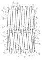
- the initial helical ridges 15' and 15a' at each end of wheels 10 and 12 are formed as partially raised ridge portions 18,18a as seen in Figs 6 and 7 . From the views in Figs. 3 and 6 , the first ridges portions 15' and 15a' are not formed on surfaces 17c and 17d of hub 14 at each end of abrasive wheels 10 and 12 for an extent of approximately 180°. The first formed partial portions 18, 18a of the ridges 15' and 15a" gradually are formed on hub 14 and respectively extend from surfaces 17c and 17d at area 19 to area 19' with a varying raised radius having an elliptical pattern ( Fig. 6 ).
- the first formed portions 18,18a at each end of the wheels 10 and 12 are integral with the initial full helical ridge portion of the respective ridges 15 and 15a.
- the peripheral edges 18', 18a' of the partial ridge portions 18,18a are beveled at an edge portion 20 to form lead-in and lead-out chamfers 10a, 10b respectively at both ends of abrasive wheels 10 and 12.
- the chamfers 10a, 10b at the rear of wheels 10, 12 are considered lead-in chamfers, because they are position adjacent the entry point of edge as it pulled through the sharpening slot.
- the chamfers 10a, 10b are lead-out chamfers where the knife exits from the slot at the front of the housing as it is pulled through wheels 10 and 12 during sharpening.
- the lead in and lead-out chamfers 10a 10b ( Fig. 6 ) eliminate the kick back on the knife blade during sharpening as occurs in the prior art and allows the abrasive wheels 10 and 12 to present an increased sharpening surface that is exposed on the wheels.
- Figs1-5 although two sharpening slots 6 and 8 containing the counter-rotating wheels 10 and 12 are shown, it is within the scope of the invention to use one or more than two slots, if desirable.
- Enhanced sharpening also is provided by the invention because the abrasive wheels 10, 12 rotate upward toward the top of the housing 4 such that both sides of the blade edge are sharpened at the same time.
- the nesting wheels 10 and 12 herein further maintain parallelism between the wheels and knife during sharpening.
- the housing 4 includes a motor enclosure 21 in which an electric motor 22 having fan 24 is mounted to be driven by an external voltage source (not shown) or alternatively by a rechargeable battery in a conventional manner.
- the electric motor 22 is a highly economical, low torque electric motor, such as a single phase induction motor.
- One type of an AC single phase motor is known as a shaded-pole motor of conventional design.
- the power drive 26 is capable of stepping down the rotation output of the motor 22, such that a significant torque is generated to the abrasive wheels 10 and 12 for effective sharpening.
- the motor 22 is provided with an output shaft 30 having an output pulley ( Figs.3 and 5 ) that drives a continuous looped belt of conventional design.
- the power drive 26 includes an upper lead pulley 34 having two pulley sections 34' and 34" is mounted on a shaft 36 rotatably carried on the housing 4. Pulleys 34a, 34b, and 34c are further rotatably mounted in spaced relationship to pulley 34 respectively on shafts 36a, 36b and 36c ( Figs. 3 and 5 ). As seen in Fig.3 , pulley 32b is laterally offset from the pulleys 34c and 34d.
- the abrasive wheels 10 are mounted in affixed manner to the opposite ends of shafts 36 and shaft 36b.
- the abrasive wheels 12 are affixed to opposite ends of shafts 36a and 36c.
- the continuous belt 32 is driven by motor 22 and is connected to pulley section 34' to rotate pulley 34 and shaft 36 in a clockwise direction
- a pair of meshing pinion gears 40 and 42 is rotatably mounted on shafts 44 and 46 beneath the pulleys 34, 34a, 34b, and 34c.
- a gear pulley assembly 50 having spaced pulley outer sections 50' and inner pulley 50" is mounted on a horizontal shaft rotated by gear 40.
- a gear pulley assembly 52 having spaced outer pulley sections 52' and inner pulley section 52" is mounted on a horizontal shaft rotated by gear 42.
- a continuous drive belt 54 extends between inner gear pulley section 50" and pulley section 34" for rotation of intermeshing gears 40 and 42 as provided by the output of the motor 22.
- a continuous belt 60 extends from gear pulley section 52" to pulley 34a to rotate shaft 36a in a counter-clockwise direction.
- a continuous belt 66 extends from gear pulley section 50' to pulley 34b to rotate shaft 36b in a clockwise direction.
- a continuous belt 68 extends from gear pulley section 52" to pulley 34c to rotate shaft 36 c in a counterclockwise direction.
- the motor drives shaft 36 and gear 40 in a clockwise direction, whereby the gears 40 and 42 rotate in opposite directions thus rotating shafts 36and 36b in a clockwise direction opposite to the counter-clockwise rotation of shafts 36a and 36c to rotate respective pairs of abrasives wheels 10, 12 in opposite interconnecting relationship.
- the blade being sharpened is generally pulled through either of sharpening slots 6 and 8 from the rear to front.
- the lead-in and lead-out chamfers 10b insure that the blade is not kicked away from the sharpener while its edge progressively either enters or exits sharpening slots 6 and 8.
Landscapes
- Engineering & Computer Science (AREA)
- Mechanical Engineering (AREA)
- Finish Polishing, Edge Sharpening, And Grinding By Specific Grinding Devices (AREA)
Abstract
Description
- This application claims priority to provisional application, S. N.
61/069,489 filed March 14, 2008 - This invention relates to abrasive sharpeners, and more particularly, to an electric powered abrasive sharpener having counter-rotating wheels.
- Numerous self powered, electric abrasive sharpeners have been developed in the past. Although some past designs produce satisfactory results, the self-powered systems in the prior art are relatively expensive and must rely on the use of heavy duty electric motors for attaining adequate torque to satisfactorily drive the abrasive wheels. Another problem associated with known electric sharpeners is the danger and inconvenience to the user experiencing kick back of the blade being sharpened. In addition, prior designs of electric sharpeners do not provide an optimum sharpening surface on the abrasive wheels for best results. Accordingly, it is desirable in the prior art to provide an economical electric sharpener capable of developing optimum torque to the wheels for effective sharpening.
- It is therefore an objective of the invention to provide an improved electric sharpener for knives, scissors, and other implements. The sharpener herein employs counter- rotating abrasive wheels with raised interconnecting abrasive threads that have a lead in and lead out chamfer to eliminate the kick back of the blade when being sharpen. The presence of the chamfers allows the grinding wheels to be flat to create a greater sharpening surface that is exposed on the wheel as compared to convex surfaces on wheels in the prior art. The unique drive train of the invention has an improved array of gears and belts that in conjunction with the sizing of the abrasive wheels allows the sharpener disclosed herein to employs a highly economical motor, while generating sufficiently high torque to the abrasive wheels for efficient sharpening. Although the electric sharpener herein is described in relation to four abrasive wheels forming two sharpening slots, the invention may be provided in accordance with teachings described as having a pair of counter rotating wheels forming one sharpening slot or more than two pairs of rotating abrasive wheels, if desired. Regardless of the number pairs of abrasive wheels employed, the pairs of wheels are respectively interconnected with a nesting design allowing for smaller wheels than compared to the prior art.
- An object of the invention is an electric abrasive sharpener for sharpening edges comprising
- a housing supporting a pair of interconnecting abrasive wheels mounted for rotatable movement in a sharpening slot formed at the top of said housing,
- each of said abrasive wheels having a raised helical thread extending continuously generally along the length of said abrasive wheels,
- a portion of one of said helical threads being disposed between two portions of the other said helical threads during rotation for contacting the edge, and
- a power drive connected to say pair of abrasive wheels for rotation in opposite directions,
- said abrasive wheels rotate upwardly toward said top of said housing, and
- said pair of wheels have a lead in section and lead out section during movement of the edge through said abrasive wheels, said lead-in section having a chamfer portion.
- Preferably, said lead-out section includes a chamfer.
- Another object of the invention is an electric abrasive sharpener for sharpening edges comprising
a pair of rotatable abrasive wheels disposed adjacent each other in an interconnected relationship to sharpen an edge moving therebetween,
one of said abrasive wheels having raised right-handed threads formed with an abrasive extending from a lead-in end to a lead-out end on said one abrasive wheel"
said other of said pair of abrasive wheels having raised left-handed threads formed with an abrasive extending from said lead- in end to lead-out end of said other abrasive wheel, and
said right-handed threads and said left-handed threads each having a chamfer section adjacent said lead-in end and said lead-out end, and.
said right handed threads and left-handed threads have a partial threaded section adjacent either said first end or said second end, said chamfer section being formed on said partial thread section. - Preferably, said right hand threads and left-hand threads have a partial threaded section adjacent both said first end and said second end., said chamfer being formed on partial threaded section on each of said partial threaded portion.
- Preferably, said pair of abrasive wheels respectively includes a cylindrical hub, said right handed threads and said left handed threads being formed on a respective hub, said partial sections extending upward from said hub to integral relationship to said right handed threads and said left handed threads.
- Preferably, said partial threaded sections having a curved upper edge generated by a varying radius.
- Another object of the invention is an electric abrasive sharpener for sharpening edges comprising
housing, - an electric motor having output shaft mounted on said housing, said output shaft having a predetermined rotational output,
- a power drive connected to said output shaft of said electric motor,
- a first and second abrasive wheel respectively mounted on first and second shafts
- on said housing, said first and second abrasive wheels being nested in interconnected relationship,
- said power drive rotating said first abrasive wheel in a first direction and rotating said second abrasive wheel in the opposite direction,
- said power drive further acting to step down the rotational output of said output shaft delivered to said parallel shafts to increase the torque applied to said first and second abrasive wheels, and
- said power drive includes a drive element between said output shaft of said electric motor and said first shaft for rotation thereof, first and second intermeshing pinion gears rotatably mounted on said housing, a gear drive element coupled between said first shaft and said first pinion gear for rotating each in opposite directions, and a second drive element coupled between said second pinion gear and said second shaft for driving said second abrasive wheel in opposite direction from said first abrasive wheel.
- Preferably, said power drive includes a drive element between said output shaft of said electric motor and said first shaft for rotation thereof, first and second intermeshing pinion gears rotatably mounted on said housing, a gear drive element coupled between said first shaft and said first pinion gear for rotating each in opposite directions, and a second drive element coupled between said second pinion gear and said second shaft for driving said second abrasive wheel in opposite direction from said first abrasive wheel.
- Preferably, said electric motor is an AC single phase motor.
- Preferably, said first and second abrasive wheels respectively include first and second opposite external abrasive threads.
-
-
Fig. 1 is a rear elevational view of the electric abrasive sharpener of the invention; -
Fig. 2 is a partial front perspective view, with parts removed, of the electric abrasive sharpener ofFig. 1 ; -
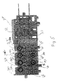
Fig. 3 is a top plan view, with parts removed, of the sharpener ofFig. 1 ; -
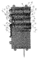
Fig. 4 is a front elevational view, with parts removed, of the sharpener ofFig 1 ; -
Fig 5 is a back elevational view, with parts removed, of the sharpener ofFig. 1 ; -
Fig. 6 is .a partial end elevational view of a pair of abrasive wheels of the sharpener ofFig 1 , and -
Fig. 7 is .a partial top plan view of a pair of abrasive wheels of the sharpener ofFig 1 . - Referring now to
Figs. 1-7 , there is illustrated the electric sharpener of the invention, generally designated byreference numeral 2. Thesharpener 2 has ahollow housing 4 made of metal or plastic and the like. For purposes of manufacture, a combination of plastic and metal may be used effectively used to formhousing 4. Thehousing 4 includes a pair of V-shaped slots 6 and 8 in which a pair of counter-rotatingabrasive wheels wheels central hub 14 respectively having integralhelical ridges hub 14 as illustrated inFigs 5 ,6 , and7 . Theridges ridges 15 form right handed threads andridges 15a form left handed threads. An abrasive material is affixed to outerperipheral surfaces 16 of theridges side walls 16, 16a thereof, and thesurfaces 17, 17a ofhub 14 respectively disposed between theridges abrasive wheels respective ridge 15 orridge 15a is disposed between two portions of the ridge of the adjacent abrasive wheel during rotation in intermeshing relationship as seen inFig. 7 . - The initial
helical ridges 15' and 15a' at each end ofwheels ridge portions Figs 6 and7 . From the views inFigs. 3 and6 , thefirst ridges portions 15' and 15a' are not formed onsurfaces 17c and 17d ofhub 14 at each end ofabrasive wheels partial portions ridges 15' and 15a" gradually are formed onhub 14 and respectively extend fromsurfaces 17c and 17d atarea 19 to area 19' with a varying raised radius having an elliptical pattern (Fig. 6 ). At area 19', the first formedportions wheels respective ridges Figs 4 ,6 and7 , theperipheral edges 18', 18a' of thepartial ridge portions edge portion 20 to form lead-in and lead-outchamfers abrasive wheels chamfers wheels chamfers wheels chamfers 10aFig. 6 ) eliminate the kick back on the knife blade during sharpening as occurs in the prior art and allows theabrasive wheels Figs1-5 , although two sharpening slots 6 and 8 containing thecounter-rotating wheels abrasive wheels housing 4 such that both sides of the blade edge are sharpened at the same time. Thenesting wheels - As seen in
Fig. 2 , thehousing 4 includes amotor enclosure 21 in which anelectric motor 22 havingfan 24 is mounted to be driven by an external voltage source (not shown) or alternatively by a rechargeable battery in a conventional manner. Because of the unique power drive 26 of the invention to be described later herein, theelectric motor 22 is a highly economical, low torque electric motor, such as a single phase induction motor. One type of an AC single phase motor is known as a shaded-pole motor of conventional design. The power drive 26 is capable of stepping down the rotation output of themotor 22, such that a significant torque is generated to theabrasive wheels abrasive wheels - The
motor 22 is provided with anoutput shaft 30 having an output pulley (Figs.3 and5 ) that drives a continuous looped belt of conventional design. The power drive 26 includes anupper lead pulley 34 having twopulley sections 34' and 34" is mounted on ashaft 36 rotatably carried on thehousing 4.Pulleys pulley 34 respectively onshafts Figs. 3 and5 ). As seen inFig.3 , pulley 32b is laterally offset from thepulleys 34c and 34d. Theabrasive wheels 10 are mounted in affixed manner to the opposite ends ofshafts 36 andshaft 36b. Theabrasive wheels 12 are affixed to opposite ends ofshafts 36a and 36c. Thecontinuous belt 32 is driven bymotor 22 and is connected to pulley section 34' to rotatepulley 34 andshaft 36 in a clockwise direction. - As seen in
Fig.5 , a pair of meshing pinion gears 40 and 42 is rotatably mounted on shafts 44 and 46 beneath thepulleys gear pulley assembly 50 having spaced pulley outer sections 50' andinner pulley 50" is mounted on a horizontal shaft rotated by gear 40. A gear pulley assembly 52 having spaced outer pulley sections 52' and inner pulley section 52" is mounted on a horizontal shaft rotated by gear 42. A continuous drive belt 54 extends between innergear pulley section 50" andpulley section 34" for rotation of intermeshing gears 40 and 42 as provided by the output of themotor 22. A continuous belt 60 extends from gear pulley section 52" to pulley 34a to rotate shaft 36a in a counter-clockwise direction. Acontinuous belt 66 extends from gear pulley section 50' topulley 34b to rotateshaft 36b in a clockwise direction. Acontinuous belt 68 extends from gear pulley section 52" topulley 34c to rotateshaft 36 c in a counterclockwise direction. - In operation, the motor drives
shaft 36 and gear 40 in a clockwise direction, whereby the gears 40 and 42 rotate in opposite directions thus rotating shafts 36and 36b in a clockwise direction opposite to the counter-clockwise rotation ofshafts 36a and 36c to rotate respective pairs ofabrasives wheels chamfers 10b insure that the blade is not kicked away from the sharpener while its edge progressively either enters or exits sharpening slots 6 and 8.
Claims (10)
- An electric abrasive sharpener for sharpening edges comprisinga housing supporting a pair of interconnecting abrasive wheels mounted for rotatable movement in a sharpening slot formed at the top of said housing,each of said abrasive wheels having a raised helical thread extending continuously generally along the length of said abrasive wheels,a portion of one of said helical threads being disposed between two portions of the other said helical threads during rotation for contacting the edge, anda power drive connected to say pair of abrasive wheels for rotation in opposite directions,said abrasive wheels rotate upwardly toward said top of said housing, andsaid pair of wheels have a lead in section and lead out section during movement of the edge through said abrasive wheels, said lead-in section having a chamfer portion.
- The sharpener according to Claim 1 wherein said lead-out section includes a chamfer.
- An electric abrasive sharpener for sharpening edges comprisinga pair of rotatable abrasive wheels disposed adjacent each other in an interconnected relationship to sharpen an edge moving therebetween,one of said abrasive wheels having raised right-handed threads formed with an abrasive extending from a lead-in end to a lead-out end on said one abrasive wheel"said other of said pair of abrasive wheels having raised left-handed threads formed with an abrasive extending from said lead- in end to lead-out end of said other abrasive wheel, andsaid right-handed threads and said left-handed threads each having a chamfer section adjacent said lead-in end and said lead-out end, and.said right handed threads and left-handed threads have a partial threaded section adjacent either said first end or said second end, said chamfer section being formed on said partial thread section.
- The sharpener according to Claim 3 wherein said right hand threads and left-hand threads have a partial threaded section adjacent both said first end and said second end., said chamfer being formed on partial threaded section on each of said partial threaded portion.
- The sharpener according to Claim 4 wherein said pair of abrasive wheels respectively includes a cylindrical hub, said right handed threads and said left handed threads being formed on a respective hub, said partial sections extending upward from said hub to integral relationship to said right handed threads and said left handed threads.
- The sharpener according to Claim 8 wherein said partial threaded sections having a curved upper edge generated by a varying radius.
- An electric abrasive sharpener for sharpening edges comprising
housing,an electric motor having output shaft mounted on said housing, said output shaft having a predetermined rotational output,a power drive connected to said output shaft of said electric motor,a first and second abrasive wheel respectively mounted on first and second shafts on said housing, said first and second abrasive wheels being nested in interconnected relationship,said power drive rotating said first abrasive wheel in a first direction and rotating said second abrasive wheel in the opposite direction,said power drive further acting to step down the rotational output of said output shaft delivered to said parallel shafts to increase the torque applied to said first and second abrasive wheels, andsaid power drive includes a drive element between said output shaft of said electric motor and said first shaft for rotation thereof, first and second intermeshing pinion gears rotatably mounted on said housing, a gear drive element coupled between said first shaft and said first pinion gear for rotating each in opposite directions, and a second drive element coupled between said second pinion gear and said second shaft for driving said second abrasive wheel in opposite direction from said first abrasive wheel. - The sharpener according to Claim 7 wherein said power drive includes a drive element between said output shaft of said electric motor and said first shaft for rotation thereof, first and second intermeshing pinion gears rotatably mounted on said housing, a gear drive element coupled between said first shaft and said first pinion gear for rotating each in opposite directions, and a second drive element coupled between said second pinion gear and said second shaft for driving said second abrasive wheel in opposite direction from said first abrasive wheel.
- The sharpener according to Claim 8 wherein said electric motor is an AC single phase motor.
- The sharpener according to Claim 9 wherein said first and second abrasive wheels respectively include first and second opposite external abrasive threads.
Applications Claiming Priority (1)
| Application Number | Priority Date | Filing Date | Title |
|---|---|---|---|
| US6948908P | 2008-03-14 | 2008-03-14 |
Publications (2)
| Publication Number | Publication Date |
|---|---|
| EP2103380A1 true EP2103380A1 (en) | 2009-09-23 |
| EP2103380B1 EP2103380B1 (en) | 2014-01-15 |
Family
ID=40743819
Family Applications (1)
| Application Number | Title | Priority Date | Filing Date |
|---|---|---|---|
| EP09155288.5A Not-in-force EP2103380B1 (en) | 2008-03-14 | 2009-03-16 | Electric abrasive sharpener |
Country Status (2)
| Country | Link |
|---|---|
| US (2) | US8206199B2 (en) |
| EP (1) | EP2103380B1 (en) |
Families Citing this family (7)
| Publication number | Priority date | Publication date | Assignee | Title |
|---|---|---|---|---|
| EP2103380B1 (en) * | 2008-03-14 | 2014-01-15 | Smith's Consumer Products, Inc. | Electric abrasive sharpener |
| US8678882B1 (en) * | 2013-06-26 | 2014-03-25 | Edgecraft Corporation | Combination sharpener assembly |
| USD863915S1 (en) | 2018-05-04 | 2019-10-22 | Smith's Consumer Products, Inc. | Electric sharpener |
| US11253968B2 (en) | 2018-08-08 | 2022-02-22 | Smith's Consumer Products, Inc. | Adjustable sharpener |
| USD867096S1 (en) | 2018-08-08 | 2019-11-19 | Smith's Consumer Products, Inc. | Adjustable sharpener |
| USD885158S1 (en) | 2019-02-07 | 2020-05-26 | Smith's Consumer Products, Inc. | Knife sharpener with two sharpening slots |
| USD884449S1 (en) | 2019-02-07 | 2020-05-19 | Smith's Consumer Products, Inc. | Knife sharpener with four sharpening slots |
Citations (3)
| Publication number | Priority date | Publication date | Assignee | Title |
|---|---|---|---|---|
| US3758993A (en) * | 1971-08-11 | 1973-09-18 | Nicholas Equipment Co | Grinding machine |
| JPH08168943A (en) * | 1994-10-05 | 1996-07-02 | Takayuki Kimijima | Dual spiral type automatic kitchen knife sharpener |
| EP1745886A1 (en) * | 2005-07-20 | 2007-01-24 | Hans-Peter Zahnd | Sharpening apparatus |
Family Cites Families (11)
| Publication number | Priority date | Publication date | Assignee | Title |
|---|---|---|---|---|
| US1115824A (en) * | 1911-04-05 | 1914-11-03 | Alexander F Jenkins | Razor-stropper. |
| US1438098A (en) * | 1921-07-11 | 1922-12-05 | Walter C Delzell | Blade-grinding device |
| US1734494A (en) * | 1927-07-30 | 1929-11-05 | Alfred A Kohlmiller | Machine for sharpening blades |
| US2035249A (en) * | 1931-11-28 | 1936-03-24 | Steiner Leo | Means for guiding the workpiece in sharpening machines |
| US3461616A (en) * | 1966-10-14 | 1969-08-19 | Gillette Co | Methods and apparatus for sharpening razor blades or similar cutting tools |
| US4038782A (en) * | 1975-11-03 | 1977-08-02 | Cozzini Artemio S | Honing mechanism |
| US4265055A (en) * | 1977-12-05 | 1981-05-05 | Warner-Lambert Company | Method and apparatus for forming a razor blade edge |
| US4807401A (en) * | 1987-06-17 | 1989-02-28 | The Gillette Company | Process and apparatus for providing cutting edges |
| US4916817A (en) * | 1987-06-17 | 1990-04-17 | The Gillette Company | Razor blade cutting edge structure |
| US6386952B1 (en) * | 2000-04-26 | 2002-05-14 | Specialty Blades, Inc. | Single station blade sharpening method and apparatus |
| EP2103380B1 (en) * | 2008-03-14 | 2014-01-15 | Smith's Consumer Products, Inc. | Electric abrasive sharpener |
-
2009
- 2009-03-16 EP EP09155288.5A patent/EP2103380B1/en not_active Not-in-force
- 2009-03-16 US US12/381,759 patent/US8206199B2/en active Active
-
2012
- 2012-06-12 US US13/494,809 patent/US8425281B2/en active Active
Patent Citations (3)
| Publication number | Priority date | Publication date | Assignee | Title |
|---|---|---|---|---|
| US3758993A (en) * | 1971-08-11 | 1973-09-18 | Nicholas Equipment Co | Grinding machine |
| JPH08168943A (en) * | 1994-10-05 | 1996-07-02 | Takayuki Kimijima | Dual spiral type automatic kitchen knife sharpener |
| EP1745886A1 (en) * | 2005-07-20 | 2007-01-24 | Hans-Peter Zahnd | Sharpening apparatus |
Also Published As
| Publication number | Publication date |
|---|---|
| US8206199B2 (en) | 2012-06-26 |
| EP2103380B1 (en) | 2014-01-15 |
| US20120258651A1 (en) | 2012-10-11 |
| US20090298398A1 (en) | 2009-12-03 |
| US8425281B2 (en) | 2013-04-23 |
Similar Documents
| Publication | Publication Date | Title |
|---|---|---|
| US8425281B2 (en) | Electric abrasive sharpener | |
| US8727836B2 (en) | Electric abrasive sharpener having adjustable abrasive wheels | |
| CN108778620B (en) | Power tool sharpeners with multi-speed abrasives | |
| US20060211345A1 (en) | Knife blade dressing apparatus | |
| US20150147945A1 (en) | Adaptable Abrasive Cutting Assembly for Sharpener | |
| US3768163A (en) | Grass trimmer sharpening device | |
| CA2703520A1 (en) | Electric abrasive sharpener | |
| US6785971B2 (en) | Electric powered rotary hacksaw | |
| US8905827B1 (en) | Dehider tool and blade therefor | |
| CN201040351Y (en) | Improved Structure of Knife Grinder | |
| WO1996004110A1 (en) | Dry shaving device | |
| US4048760A (en) | Scissors sharpener | |
| WO2008096689A1 (en) | Edged tool sharpening device | |
| EP0492746B1 (en) | Hedge trimmer | |
| US7722442B2 (en) | Knife-edge sharpening apparatus | |
| EP1466538B1 (en) | Hair removal apparatus | |
| WO2013029063A1 (en) | An improved angle grinder | |
| KR200364964Y1 (en) | Rollers for Grain and Pepper Grinders | |
| US787304A (en) | Razor-strop. | |
| FI20235151A1 (en) | Blade sharpener | |
| CN200953920Y (en) | A kind of precision grinding beauty finger machine device | |
| JP2017079933A (en) | Rotating blade and small electric device equipped with the rotating blade | |
| TWI290088B (en) | Brush unit | |
| UA72772C2 (en) | Device for hair-cutting of animals |
Legal Events
| Date | Code | Title | Description |
|---|---|---|---|
| PUAI | Public reference made under article 153(3) epc to a published international application that has entered the european phase |
Free format text: ORIGINAL CODE: 0009012 |
|
| AK | Designated contracting states |
Kind code of ref document: A1 Designated state(s): AT BE BG CH CY CZ DE DK EE ES FI FR GB GR HR HU IE IS IT LI LT LU LV MC MK MT NL NO PL PT RO SE SI SK TR |
|
| AX | Request for extension of the european patent |
Extension state: AL BA RS |
|
| 17P | Request for examination filed |
Effective date: 20100323 |
|
| 17Q | First examination report despatched |
Effective date: 20100420 |
|
| AKX | Designation fees paid |
Designated state(s): AT BE BG CH CY CZ DE DK EE ES FI FR GB GR HR HU IE IS IT LI LT LU LV MC MK MT NL NO PL PT RO SE SI SK TR |
|
| RAP1 | Party data changed (applicant data changed or rights of an application transferred) |
Owner name: SMITH'S CONSUMER PRODUCTS, INC. |
|
| GRAP | Despatch of communication of intention to grant a patent |
Free format text: ORIGINAL CODE: EPIDOSNIGR1 |
|
| INTG | Intention to grant announced |
Effective date: 20130730 |
|
| GRAS | Grant fee paid |
Free format text: ORIGINAL CODE: EPIDOSNIGR3 |
|
| GRAA | (expected) grant |
Free format text: ORIGINAL CODE: 0009210 |
|
| AK | Designated contracting states |
Kind code of ref document: B1 Designated state(s): AT BE BG CH CY CZ DE DK EE ES FI FR GB GR HR HU IE IS IT LI LT LU LV MC MK MT NL NO PL PT RO SE SI SK TR |
|
| REG | Reference to a national code |
Ref country code: CH Ref legal event code: EP Ref country code: GB Ref legal event code: FG4D |
|
| REG | Reference to a national code |
Ref country code: AT Ref legal event code: REF Ref document number: 649578 Country of ref document: AT Kind code of ref document: T Effective date: 20140215 |
|
| REG | Reference to a national code |
Ref country code: IE Ref legal event code: FG4D |
|
| REG | Reference to a national code |
Ref country code: DE Ref legal event code: R096 Ref document number: 602009021426 Country of ref document: DE Effective date: 20140227 |
|
| REG | Reference to a national code |
Ref country code: NL Ref legal event code: VDEP Effective date: 20140115 |
|
| REG | Reference to a national code |
Ref country code: AT Ref legal event code: MK05 Ref document number: 649578 Country of ref document: AT Kind code of ref document: T Effective date: 20140115 |
|
| REG | Reference to a national code |
Ref country code: LT Ref legal event code: MG4D |
|
| PG25 | Lapsed in a contracting state [announced via postgrant information from national office to epo] |
Ref country code: IS Free format text: LAPSE BECAUSE OF FAILURE TO SUBMIT A TRANSLATION OF THE DESCRIPTION OR TO PAY THE FEE WITHIN THE PRESCRIBED TIME-LIMIT Effective date: 20140515 Ref country code: NO Free format text: LAPSE BECAUSE OF FAILURE TO SUBMIT A TRANSLATION OF THE DESCRIPTION OR TO PAY THE FEE WITHIN THE PRESCRIBED TIME-LIMIT Effective date: 20140415 Ref country code: LT Free format text: LAPSE BECAUSE OF FAILURE TO SUBMIT A TRANSLATION OF THE DESCRIPTION OR TO PAY THE FEE WITHIN THE PRESCRIBED TIME-LIMIT Effective date: 20140115 |
|
| PG25 | Lapsed in a contracting state [announced via postgrant information from national office to epo] |
Ref country code: AT Free format text: LAPSE BECAUSE OF FAILURE TO SUBMIT A TRANSLATION OF THE DESCRIPTION OR TO PAY THE FEE WITHIN THE PRESCRIBED TIME-LIMIT Effective date: 20140115 Ref country code: PT Free format text: LAPSE BECAUSE OF FAILURE TO SUBMIT A TRANSLATION OF THE DESCRIPTION OR TO PAY THE FEE WITHIN THE PRESCRIBED TIME-LIMIT Effective date: 20140515 Ref country code: ES Free format text: LAPSE BECAUSE OF FAILURE TO SUBMIT A TRANSLATION OF THE DESCRIPTION OR TO PAY THE FEE WITHIN THE PRESCRIBED TIME-LIMIT Effective date: 20140115 Ref country code: FI Free format text: LAPSE BECAUSE OF FAILURE TO SUBMIT A TRANSLATION OF THE DESCRIPTION OR TO PAY THE FEE WITHIN THE PRESCRIBED TIME-LIMIT Effective date: 20140115 Ref country code: CY Free format text: LAPSE BECAUSE OF FAILURE TO SUBMIT A TRANSLATION OF THE DESCRIPTION OR TO PAY THE FEE WITHIN THE PRESCRIBED TIME-LIMIT Effective date: 20140115 Ref country code: NL Free format text: LAPSE BECAUSE OF FAILURE TO SUBMIT A TRANSLATION OF THE DESCRIPTION OR TO PAY THE FEE WITHIN THE PRESCRIBED TIME-LIMIT Effective date: 20140115 Ref country code: SE Free format text: LAPSE BECAUSE OF FAILURE TO SUBMIT A TRANSLATION OF THE DESCRIPTION OR TO PAY THE FEE WITHIN THE PRESCRIBED TIME-LIMIT Effective date: 20140115 |
|
| PG25 | Lapsed in a contracting state [announced via postgrant information from national office to epo] |
Ref country code: LV Free format text: LAPSE BECAUSE OF FAILURE TO SUBMIT A TRANSLATION OF THE DESCRIPTION OR TO PAY THE FEE WITHIN THE PRESCRIBED TIME-LIMIT Effective date: 20140115 Ref country code: HR Free format text: LAPSE BECAUSE OF FAILURE TO SUBMIT A TRANSLATION OF THE DESCRIPTION OR TO PAY THE FEE WITHIN THE PRESCRIBED TIME-LIMIT Effective date: 20140115 Ref country code: BE Free format text: LAPSE BECAUSE OF FAILURE TO SUBMIT A TRANSLATION OF THE DESCRIPTION OR TO PAY THE FEE WITHIN THE PRESCRIBED TIME-LIMIT Effective date: 20140115 |
|
| REG | Reference to a national code |
Ref country code: DE Ref legal event code: R097 Ref document number: 602009021426 Country of ref document: DE |
|
| PG25 | Lapsed in a contracting state [announced via postgrant information from national office to epo] |
Ref country code: LU Free format text: LAPSE BECAUSE OF FAILURE TO SUBMIT A TRANSLATION OF THE DESCRIPTION OR TO PAY THE FEE WITHIN THE PRESCRIBED TIME-LIMIT Effective date: 20140316 Ref country code: CZ Free format text: LAPSE BECAUSE OF FAILURE TO SUBMIT A TRANSLATION OF THE DESCRIPTION OR TO PAY THE FEE WITHIN THE PRESCRIBED TIME-LIMIT Effective date: 20140115 Ref country code: DK Free format text: LAPSE BECAUSE OF FAILURE TO SUBMIT A TRANSLATION OF THE DESCRIPTION OR TO PAY THE FEE WITHIN THE PRESCRIBED TIME-LIMIT Effective date: 20140115 Ref country code: RO Free format text: LAPSE BECAUSE OF FAILURE TO SUBMIT A TRANSLATION OF THE DESCRIPTION OR TO PAY THE FEE WITHIN THE PRESCRIBED TIME-LIMIT Effective date: 20140115 Ref country code: EE Free format text: LAPSE BECAUSE OF FAILURE TO SUBMIT A TRANSLATION OF THE DESCRIPTION OR TO PAY THE FEE WITHIN THE PRESCRIBED TIME-LIMIT Effective date: 20140115 |
|
| REG | Reference to a national code |
Ref country code: CH Ref legal event code: PL |
|
| PLBE | No opposition filed within time limit |
Free format text: ORIGINAL CODE: 0009261 |
|
| STAA | Information on the status of an ep patent application or granted ep patent |
Free format text: STATUS: NO OPPOSITION FILED WITHIN TIME LIMIT |
|
| PG25 | Lapsed in a contracting state [announced via postgrant information from national office to epo] |
Ref country code: SK Free format text: LAPSE BECAUSE OF FAILURE TO SUBMIT A TRANSLATION OF THE DESCRIPTION OR TO PAY THE FEE WITHIN THE PRESCRIBED TIME-LIMIT Effective date: 20140115 Ref country code: PL Free format text: LAPSE BECAUSE OF FAILURE TO SUBMIT A TRANSLATION OF THE DESCRIPTION OR TO PAY THE FEE WITHIN THE PRESCRIBED TIME-LIMIT Effective date: 20140115 |
|
| 26N | No opposition filed |
Effective date: 20141016 |
|
| REG | Reference to a national code |
Ref country code: IE Ref legal event code: MM4A |
|
| PG25 | Lapsed in a contracting state [announced via postgrant information from national office to epo] |
Ref country code: LI Free format text: LAPSE BECAUSE OF NON-PAYMENT OF DUE FEES Effective date: 20140331 Ref country code: IE Free format text: LAPSE BECAUSE OF NON-PAYMENT OF DUE FEES Effective date: 20140316 Ref country code: CH Free format text: LAPSE BECAUSE OF NON-PAYMENT OF DUE FEES Effective date: 20140331 |
|
| REG | Reference to a national code |
Ref country code: DE Ref legal event code: R097 Ref document number: 602009021426 Country of ref document: DE Effective date: 20141016 |
|
| PG25 | Lapsed in a contracting state [announced via postgrant information from national office to epo] |
Ref country code: SI Free format text: LAPSE BECAUSE OF FAILURE TO SUBMIT A TRANSLATION OF THE DESCRIPTION OR TO PAY THE FEE WITHIN THE PRESCRIBED TIME-LIMIT Effective date: 20140115 |
|
| PG25 | Lapsed in a contracting state [announced via postgrant information from national office to epo] |
Ref country code: MT Free format text: LAPSE BECAUSE OF FAILURE TO SUBMIT A TRANSLATION OF THE DESCRIPTION OR TO PAY THE FEE WITHIN THE PRESCRIBED TIME-LIMIT Effective date: 20140115 |
|
| PG25 | Lapsed in a contracting state [announced via postgrant information from national office to epo] |
Ref country code: MC Free format text: LAPSE BECAUSE OF FAILURE TO SUBMIT A TRANSLATION OF THE DESCRIPTION OR TO PAY THE FEE WITHIN THE PRESCRIBED TIME-LIMIT Effective date: 20140115 |
|
| REG | Reference to a national code |
Ref country code: FR Ref legal event code: PLFP Year of fee payment: 8 |
|
| PG25 | Lapsed in a contracting state [announced via postgrant information from national office to epo] |
Ref country code: IT Free format text: LAPSE BECAUSE OF FAILURE TO SUBMIT A TRANSLATION OF THE DESCRIPTION OR TO PAY THE FEE WITHIN THE PRESCRIBED TIME-LIMIT Effective date: 20140115 Ref country code: GR Free format text: LAPSE BECAUSE OF FAILURE TO SUBMIT A TRANSLATION OF THE DESCRIPTION OR TO PAY THE FEE WITHIN THE PRESCRIBED TIME-LIMIT Effective date: 20140416 Ref country code: BG Free format text: LAPSE BECAUSE OF FAILURE TO SUBMIT A TRANSLATION OF THE DESCRIPTION OR TO PAY THE FEE WITHIN THE PRESCRIBED TIME-LIMIT Effective date: 20140115 |
|
| PG25 | Lapsed in a contracting state [announced via postgrant information from national office to epo] |
Ref country code: HU Free format text: LAPSE BECAUSE OF FAILURE TO SUBMIT A TRANSLATION OF THE DESCRIPTION OR TO PAY THE FEE WITHIN THE PRESCRIBED TIME-LIMIT; INVALID AB INITIO Effective date: 20090316 Ref country code: TR Free format text: LAPSE BECAUSE OF FAILURE TO SUBMIT A TRANSLATION OF THE DESCRIPTION OR TO PAY THE FEE WITHIN THE PRESCRIBED TIME-LIMIT Effective date: 20140115 |
|
| PGFP | Annual fee paid to national office [announced via postgrant information from national office to epo] |
Ref country code: GB Payment date: 20160627 Year of fee payment: 8 |
|
| PGFP | Annual fee paid to national office [announced via postgrant information from national office to epo] |
Ref country code: FR Payment date: 20160628 Year of fee payment: 8 |
|
| PGFP | Annual fee paid to national office [announced via postgrant information from national office to epo] |
Ref country code: DE Payment date: 20160628 Year of fee payment: 8 |
|
| REG | Reference to a national code |
Ref country code: DE Ref legal event code: R119 Ref document number: 602009021426 Country of ref document: DE |
|
| GBPC | Gb: european patent ceased through non-payment of renewal fee |
Effective date: 20170316 |
|
| REG | Reference to a national code |
Ref country code: FR Ref legal event code: ST Effective date: 20171130 |
|
| PG25 | Lapsed in a contracting state [announced via postgrant information from national office to epo] |
Ref country code: FR Free format text: LAPSE BECAUSE OF NON-PAYMENT OF DUE FEES Effective date: 20170331 Ref country code: DE Free format text: LAPSE BECAUSE OF NON-PAYMENT OF DUE FEES Effective date: 20171003 |
|
| PG25 | Lapsed in a contracting state [announced via postgrant information from national office to epo] |
Ref country code: GB Free format text: LAPSE BECAUSE OF NON-PAYMENT OF DUE FEES Effective date: 20170316 |
|
| PG25 | Lapsed in a contracting state [announced via postgrant information from national office to epo] |
Ref country code: MK Free format text: LAPSE BECAUSE OF FAILURE TO SUBMIT A TRANSLATION OF THE DESCRIPTION OR TO PAY THE FEE WITHIN THE PRESCRIBED TIME-LIMIT Effective date: 20140115 |