EP2103353A2 - Fibrous particle generating apparatus and test system - Google Patents
Fibrous particle generating apparatus and test system Download PDFInfo
- Publication number
- EP2103353A2 EP2103353A2 EP08170144A EP08170144A EP2103353A2 EP 2103353 A2 EP2103353 A2 EP 2103353A2 EP 08170144 A EP08170144 A EP 08170144A EP 08170144 A EP08170144 A EP 08170144A EP 2103353 A2 EP2103353 A2 EP 2103353A2
- Authority
- EP
- European Patent Office
- Prior art keywords
- fibrous
- base material
- fibrous particle
- holding unit
- generating apparatus
- Prior art date
- Legal status (The legal status is an assumption and is not a legal conclusion. Google has not performed a legal analysis and makes no representation as to the accuracy of the status listed.)
- Withdrawn
Links
Images





Classifications
-
- B—PERFORMING OPERATIONS; TRANSPORTING
- B02—CRUSHING, PULVERISING, OR DISINTEGRATING; PREPARATORY TREATMENT OF GRAIN FOR MILLING
- B02C—CRUSHING, PULVERISING, OR DISINTEGRATING IN GENERAL; MILLING GRAIN
- B02C19/00—Other disintegrating devices or methods
- B02C19/20—Disintegrating by grating
-
- G—PHYSICS
- G01—MEASURING; TESTING
- G01M—TESTING STATIC OR DYNAMIC BALANCE OF MACHINES OR STRUCTURES; TESTING OF STRUCTURES OR APPARATUS, NOT OTHERWISE PROVIDED FOR
- G01M99/00—Subject matter not provided for in other groups of this subclass
Definitions
- the present invention relates to a technique in generation of fibrous particles that are to be used in evaluation tests for resistance of obj ect apparatuses to fibrous particles.
- An apparatus that includes therein a heat emitting element such as an electric/electronic parts and units uses a fan or the like to ventilate the inside the apparatus and cool the parts and units. That keeps the inside temperature of the apparatus from rising in order to stabilize the operation of the apparatus.
- a heat emitting element such as an electric/electronic parts and units uses a fan or the like to ventilate the inside the apparatus and cool the parts and units. That keeps the inside temperature of the apparatus from rising in order to stabilize the operation of the apparatus.
- Such dust generated in house mainly contains fibrous particles having a longitudinal diameter (i.e., the length in the longitudinal length) of approximately 50-100 ⁇ m.
- Air containing such fibrous particles is taken into an apparatus by a fan or the like, whereupon lint dust is clogged and accumulated inside the apparatus. That may be a cause of a rise in the temperature inside the apparatus, and finally one of the causes of breakdown.
- a conventional method for evaluating resistance to dust mainly uses sand dust of 50 ⁇ m or smaller, but does not use dust of this kind of fibrous particle generated in houses and the equivalents for evaluation.
- no method is provided which obtains fibrous particles generated in houses, or no method is established which evaluates using such fibrous particles.
- a fibrous particle generating apparatus comprising: abase material containing a fibrous material; a holding unit holding the base material; a fibrous particle generator generating fibrous particles by chafing the base material; and a movement unit moving the holding unit such that the base material held by holding unit is chafed against the fibrous particle generator.
- test system 1-1 and fibrous particle generating apparatus 10 according to the first embodiment with reference to Fig. 1 .
- test system 1-1 of the first embodiments comprises fibrous particle generating apparatus 10 that generates fibrous particles, object apparatus 2 that is to undergo evaluation of resistance to fibrous particles, exhaust duct 3, and box (specific space) 4.
- Object apparatus 2 is, for example, a personal computer or a server with fan 2a, and takes outside air into the apparatus and exits the air from the apparatus.
- Fan 2a can be omitted from object apparatus 2 if object apparatus 2 alternatively has a mechanism to take outside air into the apparatus and exhaust air from the apparatus.
- Exhaust duct 3 includes filter 3a to capture fibrous particles and dusts (hereinafter collectively exhaust dust) contained in the exhaust air from object apparatus 2.
- exhaust duct 3 is connected to the outlet of object apparatus 2 and filters off the exhaust dust contained in the exhaust air from object apparatus 2, so that the exhaust dust is not ejected from exhaust duct 3.
- test system 1-1 preferably comprises box 4 that accommodates object apparatus 2, exhaust duct 3, and fibrous particle generating apparatus 10 so that the resistance to fibrous particles is evaluated in an enclosed space. If object apparatus 2 has such a structure that matter except fibrous particles generated by fibrous particle generating apparatus 10 does not enter object apparatus 2, box 4 is not essential.
- test system 1-1 is preferably configured to be positioned in an enclosed space (i.e., box 4) and not to let fibrous particles and the like which have entered object apparatus 2 and which have been ejected from the apparatus re-enter object apparatus 2.
- broken arrows 5 in Fig. 1 represents descent of fibrous particles generated by fibrous particle generating apparatus 10; block arrow 6a represents a flow of air containing the fibrous particles which flow is caused by fan 2a included in object apparatus 2; block arrow 6b represents a flow of exhaust air from object apparatus 2; block arrow 6c represents a flow of the exhaust air through exhaust duct 3; and block arrow 6d represents a flow of the exhaust air out of exhaust duct 3.
- Symbol 7 represents lint dust accumulated inside object apparatus 2.
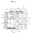
- Fig. 2 is a perspective view of fibrous particle generating apparatus 10 of the first embodiment.
- Fibrous particle generating apparatus 10 comprises main frame 11, fibrous particle generator 12, base material 13, holding unit 14, connection 15, bearing 16, driving motor 17, and driving belt 18, as shown in Fig. 2 .
- Main frame 11 is formed of side frames 11a, front frame 11b, rear frame 11c, top frame 11d, and bottom frame 11e.
- Top frame 11d has opening 11d-1 through which axis 15a of connection 15 penetrates, and opening 11d-2 through which the rotation axis of driving motor 17 penetrates.
- top frame 11d has pulley 11d-3 for secure the rotation of driving belt 18.
- Bottom frame 11e has opening 11e-1 facing fibrous particle generator 12.
- Fibrous particle generator 12 grinds base material 13 into fibrous particle by chafing base material 13, and is in the form of, for example, a mesh plate.
- fibrous particles generated by fibrous particle generating apparatus 10 are fibrous or needle-shape particles having a length in the range of from a specific lower limit inclusive to a specific upper limit (i.e., within a specific length range) as shown by particles 13a-13d in Fig. 3(a) to Fig. 3(d) .
- the fibrous particles generated by fibrous particle generating apparatus 10 preferably has the longitudinal diameter (in the longitudinal direction) in the range of from about 25 ⁇ m to about 200 ⁇ m, more preferably in the range of from about 50 ⁇ m to about 100 ⁇ m.
- mesh plate serving as fibrous particle generator 12 (hereinafter simply called mesh plate 12) is fixed to bottom frame 11e. In other words, mesh plate 12 is opposed to the lower end of base material 13 held by holding unit 14.
- bottom frame 11e has opening 11e-1 at a position corresponding (opposing) tomeshplate 12, specifically in this example, vertically under the mesh of mesh plate 12. With this structure, fibrous particles generated by chafing base material 13 against mesh plate 12 fall freely through opening 11e-1.
- Base material 13 takes a bar shape, more particularly in this example, a cylindrical shape, and is formed by compressing fiber exemplified by a number of sheets of paper or tissue paper into a bar shape.
- Fibrous particle generating apparatus 10 of the first embodiment includes a number of base materials 13 each in a bar shape.
- Fiber compressed into base material 13 may be vegetable fiber, animal fiber, or synthetic fiber, and specifically may be cotton wool, cloth, hair of animal, silk, acrylic fiber, nylon fiber, or polyethylene fiber as an alternative to paper or tissue paper.
- base material 13 is not limited to compressing into a bar shape.
- base material 13 is formed by rolling or binding fiber into a bar, by shaping wood fiber into a bar, or by shaping fiber fragment into a bar.
- Fibrous particle generating apparatus 10 chafes base material 13 against mesh plate 12 to shred and/or peel off fiber of paper or tissue paper forming base material 13 at the contact with mesh plate 12. Fibrous particles are thereby generated.
- mesh plate 12 is higher in hardness than base material 13 and has edges to shred or peel off the fiber of base material 13.
- Fig. 4 shows an enlargement of a part of mesh plate 12 included in fibrous particle generating apparatus 10. As shown in Fig. 4 , crosses 12a of grids of mesh plate 12 functions as the edges. Alternatively, mesh plate 12 may have wavy (serrated) grids each of which functions as the edge.
- Fig. 4 attached reference number 12a to a single cross for simplification of the drawing, but all the positions at which grids of mesh plate 12 cross can be regarded as crosses 12a.
- edges of mesh plate 12 should not always be sharp. Since it is sufficient that the edges generate fibrous particles when base material 13 is chafed against mesh plate 12, the properties of edges can vary according to the properties of base material 13, such as the kind of the material and the compression rate.
- Holding unit 14 holds base material 13. Fibrous particle generating apparatus 10 has four holding units 14, provided one for each base material 13.
- holding unit 14 is arranged such that base material 13 is in contact with mesh plate 12, as shown in Fig. 2 .
- holding unit 14 includes holder 14a and cylindrical holder support 14b, as shown in Fig. 2 .
- Holder 14a directly holds base material 13 such that base material 13 projects towards mesh plate 12, and is in the form of a cylinder formed of two parts 14a-1 and 14a-2 as shown in, for example, Fig. 6 .
- Holder 14a is formed by coupling parts 14a-1 and 14a-2 which are sandwiching base material 13. Parts 14a-1 and 14a-2 are coupled by bolts and nuts (both not shown).
- Cylindrical holder support 14b slidably accommodates holder 14a such that base material 13 projects towards mesh plate 12.
- Base material 13 held inside holder 14a is able to slide inside cylindrical holder support 14b downward in the direction of arrow X in the drawing.
- base material 13 is configured to come into contact with mesh plate 12 under the weights of base material 13 itself and cylindrical holder support 14b.
- Base material 13 is in contact with mesh plate 12 under a specific pressure caused from the weights of base material 13 and cylindrical holder support 14b, and moves downward (in the direction of arrow X) in line with grinding base material 13 by mesh plate 12.
- cylindrical holder support 14b preferably has support tip 14c at the lower opening, which is facing mesh plate 12 and through which base material 13 passes, in order to support base material 13.
- Support tip 14c is preferably provided around the entire circumference of the opening.
- Figs. 7 (a) and 7 (b) show the section of only cylindrical holder support 14b for description of the state of holder 14a and base material 13 accommodated in cylindrical holder support 14b.
- base material 13 rotates on mesh plate 12 while base material 13 moves on mesh plate 12. Therefore, if base material 13 has a long portion projecting out of holder 14a as shown in Fig. 7 (a) , the projecting portion may be broken or deformed which is caused from buckling.
- support tip 14c is formed on cylindrical holder support 14b.
- Support tip 14c has no need for contacting with stopping base material 13 and is sufficiently in contact with base material 13 on the move. Support tip 14c is formed to keep a slight space with respect to base material 13.
- Support tip 14c serves a function as a stopper that prevents holder 14a from approaching mesh plate 12 closer than a predetermined space when base material 13 is worn out, as shown in Fig. 7(b) .
- the presence of support tip 14c can avoid undesired contact between holder 14a and mesh plate 12 caused from base material 13 wearing out while fibrous particle generating apparatus 10 is in operation.
- connection 15 connects thereto a number of (in the illustrated example, four) holding units 14.
- Connection 15 is supported by bearing 16 fixed to top frame 11d of main frame 11 with screws, bolts or the like to be rotatable with respect to Mesh plate 12.
- connection 15 includes axis 15a, which bearing 16 pivotably supports.
- connection 15 includes connection plate 15b, coupling plate 15c, and pulley 15d.
- Connection plate 15b is coupled to each of four holding units 14, as shown in Fig. 8 , and has openings corresponding one for each holding unit 14. Each holding unit 14 is fitted to the corresponding opening and is thereby coupled to connection plate 15b.
- connection plate 15b does not limit the manner of connection (coupling) between connection plate 15b and each holding unit 14, but preferably, each holding unit 14 is firmly coupled to connection plate 15b so as not to rotate and move in conjunction with rotation of connection plate 15b.
- Connection plate 15b which is in connection with holding unit 14, is further coupled to coupling plate 15c, which is in connection with axis 15a, by means of, for example, bolts 15e and 15f.
- bolts 15e and 15f In the example of Fig. 2 , four bolts establish the connection between coupling plate 15c and connection plate 15b.
- coupling plate 15c and connection plate 15b have screw holes through which the bolts are to be screwed. As shown in Fig. 8 , screw holes 15b-1 to 15b-4 are formed on connection plate 15b.
- Pulley 15d is arranged on the top end of axis 15a.
- rotation of axis 15a rotates coupling plate 15c, and pivotably rotates connection plate 15b, which is coupled to coupling plate 15c and which holds holding units 14, around axis 15a.
- Driving motor 17 is the power source to rotate connection 15 and includes pulley 17a attached to the driving shaft.
- Driving belt 18 is a continuous belt looped over pulley 17a of the driving shaft, pulley 15d of connection 15, and pulley 11d-3.
- Driving motor 17 rotates the driving shaft, which causes pulley 17a to rotate, and the rotation power is transmitted to pulley 15d of axis 15a via driving belt 18 to thereby rotate connection 15 and holding units 14.
- Rotation of holding units 14 causes base materials 13 held by holding units 14 to rotate on fibrous particle generator 12 around axis 15a, and base materials 13 are chafed against fibrous particle generator 12.
- Driving motor 17 and driving belt 18 functions as a movement unit that moves holding units 14 in such a manner that base materials 13 held by holding units 14 are chafed against fibrous particle generator 12.
- driving motor 17 and driving belt 18 serving as the movement unit rotates and moves holding unit 14 and connection 15 with respect to fibrous particle generator 12.
- base materials 13 held in holding units 14 are chafed against fibrous particle generator 12 and thereby ground into fibrous particles.
- Fibrous particle generating apparatus 10 includes controller 17b that controls the rotation speed of driving motor 17.
- Controller 17b previously includes table 17c that retains the association of an amount of generation of fibrous particles per unit time with the rotation speed, and controls the rotation speed of driving motor 17 to generate requisite fibrous particles for experiments on the basis of table 17c.
- Table 17c is preferably created beforehand on the basis of the result of experiments.
- an amount of generated fibrous particles can be calculated from the weights of base material 13 before and after the operation of fibrous particle generating apparatus 10.
- the weight of fibrous particles generated in a predetermined time period may be the difference between the weights of base material 13 before and after the operation of fibrous particle generating apparatus 10 for the predetermined time period or may be a value obtained by multiplying the weight difference by a specific coefficient.
- box 4 of fibrous particle generating apparatus 10 has the interior wall black in color and base material 13 colored white, yellow or fluorescent color.
- spotlight 8 may be installed to project intensive linear visible light to the position under fibrous particle generating apparatus 10. That also enhances the visibility of fibrous particles generated by fibrous particle generating apparatus 10.
- fibrous particle generating apparatus 10 tests the operation of object apparatus 2 for a predetermined time period. Specifically, on the basis of the result of measurement as to whether or not object apparatus 2 is operating correctly and measurement of the temperature or others inside object apparatus 2, fibrous particle generating apparatus 10 can evaluate the resistance of object apparatus 2 to dust caused from the generated fibrous particles, i.e., the resistance to fibrous particles.
- Embodiments of the present invention are not limited to the method of the test and the evaluation objects in test system 1-1 to the above.
- holding units 14 holding base materials 13 made of fibrous substance moves so as to chafe against fibrous particle generator 12 depending on the movement of driving motor 17 and driving belt 18 serving as the movement unit.
- fibrous particles having a longitudinal diameter (preferably 50-100 ⁇ m) or more in contrast to fibrous particles with a longitudinal diameter of 50 ⁇ m or less which have conventionally been used for dust evaluation.
- test system 1-1 can carry out stable evaluation and test using fibrous particles on object apparatus 2 with certainty.
- test and evaluation use fibrous particle generator 12 that grinds base materials 13 by chafing base material 13 into fibrous particles, generation of fibrous particles is secured and test system 1-1 and fibrous particle generating apparatus 10 can be realized in an extremely low cost.
- fibrous particle generator 12 is positioned to be opposed to the lower end of base material 13 held in holding unit 14, positioning fibrous particle generating apparatus 10 over object apparatus 2, more preferably over an air intake of object apparatus 2, makes it possible to provide object apparatus 2 with fibrous particles generated in fibrous particle generating apparatus 10 by merely falling freely the particles. That can simplify the configuration of test system 1-1.
- the configuration requires no additional mechanism dedicated to providing fibrous particles generated by fibrous particle generator 12. Therefore, it is possible to stably provide fibrous particles generated at a low cost.
- holding units 14 are arranged such that base materials 13 are in contact with fibrous particle generator 12, the movement unit can chafe base material 13 against fibrous particle generator 12 simply by moving (in this example, rotating) holding unit 14. Consequently, fibrous particles can be generated in such an extremely simple structure.
- each holding unit 14 includes holder 14a that directly holds base material 13 and cylindrical holder support 14b that slidably inserts the holder 14a therein. It is possible to contact base material 13 with fibrous particle generator 12 under the weights base material 13 itself and holder 14a, so that simple parallel movement of base material 13 to fibrous particle generator 12 stably generates fibrous particles.
- support tip 14c that supports base material 13 at the lower opening cylindrical holder support 14b, which opening faces fibrous particle generator 12 and through which base material 13 passes it is possible to prevent base material 13 from being deformed by buckling while base material 13 is pivoting around axis 15a. Generation of fibrous particles can be realized more stably.
- fibrous particulates can be generated more stably with the presence of driving motor 17 and driving belt 18, serving as the movement unit, that pivots holding unit 14 around axis 15a with respect to fibrous particle generator 12 via the rotation of connection 15.
- base material 13 moves in a single direction or moves simply back and forth on fibrous particle generator 12
- either side of base material 13 is chafed against fibrous particle generator 12 to cause unsymmetrical wear of base material 13, which may hinder stable supply of fibrous particles.
- embodiments of the present invention move rotating base material 13 on fibrous particle generator 12, so that base material 13 is free from unsymmetrical wear and is capable of stably providing fibrous particles anytime.
- test system 1-2 and fibrous particle generating apparatus 20 according to a second embodiment of the present invention will now be detailed.
- test system 1-2 includes fibrous particle generating apparatus 20, object apparatus 2, exhaust duct 3, box 4, and spotlight 8.
- Test system 1-2 is different only in configuration of the fibrous particle generating apparatus from test system 1-1 of the above first embodiment.
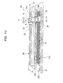
- fibrous particle generating apparatus 20 slidingly moves as shown in Fig. 10 .
- fibrous particle generating apparatus 20 slidingly moves as shown in Fig. 10 .
- like reference numbers designate similar parts or elements throughout several views of different illustrated examples.
- fibrous particle generating apparatus 20 includes mesh plate 12, base material 13, installation basement 21, installation rails 22a and 22b, holding unit 24, connection 25, guide 26, slider 30, and slider moving section 40.
- Mesh plate 12 serving as the fibrous particle generator is installed to installation basement 21 by installation rails 22a and 22b.
- installation rails 22a and 22b are coupled to installation basement 21 by screwing or other method. Thereby, mesh plate 12 is installed to installation basement 21.
- mesh plate 12 is positioned to be opposed to the lower end of base material 13 held by holding unit 24.
- Installation basement 21 has opening 21a at a position opposite to mesh plate 12.
- fibrous particles generated by mesh plate 12 of fibrous particle generating apparatus 20 falls freely downward similarly to fibrous particle generating apparatus 10 of the first embodiment.
- Holding unit 24 holds base material 13 and is arranged such that base material 13 is in contact with mesh plate 12.
- base material 13 is directly held by holder 24a of holding unit 24 so as to project towards mesh plate 12.
- Holder 24a is in the form of a cylinder formed of two parts 24a-1 and 24a-2 as shown in Fig. 6 .
- Holder 24a is formed by coupling two parts 24a-1 and 24a-2 sandwiching base material 13.
- holder 24a is slidably inserted into cylindrical holder support 24b such that base material 13 projects toward mesh plate 12.
- Base material 13 comes into contact with mesh plate 12 under the weights of base material 13 and holder 24a similarly to the first embodiment.
- Connection 25 couples (combines) base material 13 held by holding unit 24 to slider 30 that slides in the direction of arrow Y in the drawing (hereinafter called the sliding direction Y) back and forth with the air of slider moving section 40.
- cylindrical holder support 24b of holding unit 24 is coupled to connection 25 by, for example, bolts or screws; and connection 25 is coupled to slider 30 by, for example, bolts or screws.
- cylindrical holder support 24b into which holder 24a holding base material 13 is inserted moves back and forth in the sliding direction Y.
- Connection 25 has an opening through which holder 24a penetrates on the position facing (opposed to) cylindrical holder support 24b.
- Fig. 11 is the A-A' sectional view of Fig. 10 .
- Slider 30 and slider moving section 40 are not detailed in Fig. 11 for simplification purpose, but are to be described in detail below with reference to Fig. 12 .
- holder 24a inserted into cylindrical holder support 24b penetrates connection 25.
- Base material 13 held by holder 24a is in direct contact with fibrous particle generator 12.
- Guide 26 is coupled to connection 25 by, for example, bolts or screws, and is in slidably contact with installation rail 22a.
- guide 26 is slidably attached to installation rail 22a to allow connection 25 and holding unit 24 to move back and forth in the slide direction Y.
- connection 25 and holding unit 24 are able to stably move back and forth along the longitudinal direction (in this example, identical with the slide direction Y) of installation rail 22a.
- Slider 30 and slider moving section 40 function as a movement unit that moves holding unit 24 back and forth along mesh plate 12, being interposed by connection 25.
- Fig. 12 shows the B-B' section of Fig. 10 .
- Slider moving section 40 includes driving motor 41, driving axis 42, bearings 43a-43c, screw axis 44, and cover 45.
- driving motor 41, driving axis 42, and screw axis 44 are not sectioned for the purposes of simplification and description of function.
- Driving motor 41 rotates driving axis 42 both clockwise and counterclockwise.
- Driving motor 41 is rotatably supported by bearings 43a-43c.
- Screw axis 44 is coupled to driving axis 42. Screw axis 44 has spiral groove 44a on the circumference surface.
- Screw axis 44 is rotatable in the both directions similarly to driving axis 42.
- Driving motor 41, driving axis 42, bearings 43a-43c are covered with cover 45.
- Slider 30 has protrusions 31 and 32 that come into contact with spiral groove 44a of screw axis 44.
- Slider 30 is configured to be fit into screw axis 44 at protrusions 31 and 32, each of which is contact with screw axis 44 at spiral groove 44a.
- Rotation of screw axis 44 in either direction by driving motor 41 moves slider 30 in the corresponding direction and rotation of screw axis 44 in the other direction by driving motor 41 moves slider 30 in the reverse direction opposite to the above movement.
- slider 30 moves back and forth in the slide direction Y by clockwise and counterclockwise rotation of screw axis 44 actuated by driving motor 41.
- driving motor 41 rotates screw axis 44 and slider 30 thereby moves back and forth slider 30.
- holding unit 24 coupled to connection 25 moves back and forth, so that base material 13 held by holding unit 24 moves back and forth on mesh plate 12 in the slide direction Y, keeping the contact with mesh plate 12.
- base material 13 is chafed against mesh plate 12, which grinds base material 13 into fibrous particles.
- controller 41a that controls driving motor 41 preferably controls the rotation speed of driving motor 41 on the basis of table 41b in fibrous particle generating apparatus 20.
- Table 41b is created on the basis of the result of experiments, and retains the association of an amount of generation of fibrous particles per unit time with the sliding speed of base material 13 or the rotation speed of the driving motor.
- the grids of mesh plate 12 is preferably configured to cross the direction in which holding unit 24 (i.e., base material 13) moves back and forth.
- Mesh plate 12 is preferably arranged such that the edges and crosses 12a are not parallel to the slide direction Y, in other words, such that only a specific portion of base material 13 is not ground. That can prevent such a specific portion of base material 13 from being ground.
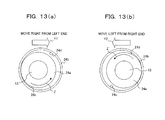
- holder 24a and cylindrical holder support 24b of holding unit 24 is preferably configured as shown in Figs. 13(a) and 13(b) , which are top view of holding unit 24 seen from the position directly over holding unit 24.
- holder 24a is in the form of a cylinder and that cylindrical holder support 24b is in the form of a cylinder having an inner diameter larger than the outer diameter of holder 24a, so that holder 24a is inserted into cylindrical holder support 24b, keeping a clearance between holder 24a and cylindrical holder support 24b.
- cylindrical holder support 24b includes first protrusion 24c that comes into contact with holder 24a moving in one direction of the back-and-forth movement (i.e., the slide direction Y) which protrusion is positioned on a first region of the inner circumference; and second protrusion 24d that comes into contact with holder 24a moving in the other direction of the back-and-forth movement which protrusion is positioned on a second region of the inner circumference opposed to the first region.
- first protrusion 24c that comes into contact with holder 24a moving in one direction of the back-and-forth movement (i.e., the slide direction Y) which protrusion is positioned on a first region of the inner circumference
- second protrusion 24d that comes into contact with holder 24a moving in the other direction of the back-and-forth movement which protrusion is positioned on a second region of the inner circumference opposed to the first region.
- first protrusion 24c can contact with the outer circumference of holder 24a in a state in which holder 24a is in contact with the inner circumference cylindrical holder support 24b when holding unit 24 is on the left end of the slidable range.
- second protrusion 24d can contact with the outer circumference of holder 24a in a state in which holder 24a is in contact with the inner circumference cylindrical holder support 24b when holding unit 24 is on the right end of the slidable range.
- first protrusion 24c in the first region as shown in Fig. 13 (a) makes a difference between the frictional resistance of holder 24a at the direct contact between holder 24a and cylindrical holder support 24b and the frictional resistance of holder 24a at the contact between holder 24a and first protrusion 24c when holding unit 24 is moving right from the left end of the slidable range.
- the difference in the frictional resistance rotates holder 24a in the direction of arrow Z in the drawing, that is, rotates counterclockwise.
- the frictional resistance between holder 24a and first protrusion 24c is larger than that between holder 24a and cylindrical holder support 24b.
- the block arrow Y1 in Fig. 13 (a) indicates the direction of movement of holding unit 24.
- second protrusion 24d in the second region makes a difference between the frictional resistance of holder 24a at the direct contact between holder 24a and cylindrical holder support 24b and the frictional resistance of holder 24a at the contact between holder 24a and second protrusion 24d when holding unit 24 is moving left from the right end of the slidable range.
- the difference in the frictional resistance rotates holder 24a in the direction of arrow Z in the drawing, that is, rotates counterlockwise.
- the frictional resistance between holder 24a and second protrusion 24d is larger than that between holder 24a and cylindrical holder support 24b.
- the block arrow Y2 indicates the direction of movement of holding unit 24 in Fig. 13(b) .
- mesh plate 12 does not always grinds the same portion of base material 13, so that uneven grinding of base material 13 and resultant inferior generation of fibrous particles can be surely avoided.
- test system 1-2 and fibrous particle generating apparatus 20 of the second embodiment can obtain the same effects and advantages as those of the first embodiment.
- fibrous particle generating apparatus 20 of the above first embodiment includes four base materials 13 and four holding units 14 corresponding one to each base material 13, to which embodiments of the present invention are not limited.
- Embodiments of the present invention do not limit the number of base materials 13 and that of holding units 14 included in fibrous particle generating apparatus 10.
- fibrous particle generating apparatus 20 of the second embodiment is assumed to have single base material 13 and corresponding single holding unit 24 in the description.
- embodiments of the present invention are not limited to this and do not limit the number of base materials 13 and that of holding units 24 included in fibrous particle generating apparatus 20.
- test systems 1-1 and 1-2 have boxes 4.
- Box 4 can be dispensable if object apparatus 2 is connected to fibrous particle generating apparatuses 10 and 20 such that all the fibrous particles generated by fibrous particle generating apparatuses 10 and 20 enter object apparatus 2.
- Fibrous particle generating apparatuses 10 and 20 of the first and second embodiments control driving motors 17 and 41 under control of controllers 17b and 41a, respectively in order to control an amount of fibrous particulate to be generated.
- embodiments of the present invention are not limited to this.
- variation in weights of holders 14a and 24a may vary the pressure that base material 13 applies to mesh plate 12 in order to control an amount of generation of fibrous particles.
- variation in weights of holders 14a and 24a are based on a table retaining the association between the weights of holders 14a and 24a and an amount of generation of fibrous particulates obtained by experiments and others.
- holders 14a and 24a are preferably replaced with other holders 14a and 24a that are different in weight.
- an amount of fibrous particulate to be generated may be controlled by a combination of the above control by controller 17b and 41a and a variation in weight of holders 14a and 24a.
- replacement of mesh plate 12 may modify the length of fibrous particles to be generated. For example, narrowing the grids of mesh plates may generate relatively short fibrous particles; and conversely winding the grids of mesh plate 12 may generate relatively long fibrous particles. Still further, mesh plate 12 may have thin-serrated edge grid so as to generate short fibrous particles. In other words, fibrous particle generating apparatuses 10 and 20 preferably replace mesh plate 12 with another mesh plate having various shapes and specifications, depending on desired fibrous particles to be generated.
- test systems 1-1 and 1-2 may modify the adherence of fibrous particles generated by fibrous particle generating apparatuses 10 and 20 of the foregoing embodiments.
- smoke e.g., cigarette smoke
- carrier see block diagram 6a in Fig. 1
- the adherence of fibrous particulate is heightened by raising humidity in box 4.
- the adjustment of the humidity and the temperature in box 4 variably controls the adherence of generated fibrous particles.
- the adherence is increased by electrically charging the generated fibrous particles.
- mesh plate 12 In order to improve the diffusion and the quality of fibrous particles generated by mesh plate 12, mesh plate 12 maybe shaken at regular intervals so that fibrous particles are refrained from clogging or snagging particularly at crosses 12a. A shake of mesh plate 12 can fall clogging or snagging fibrous particles and thereby desired fibrous particles can be stably supplied. The same effect can be achieved by a mechanism that has a brush sliding in contact with mesh plate 12 and automatically clean mesh plate 12 with the brush regularly.
- Mesh plate 12 may be grounded for avoiding electrically charging of mesh plate 12. That can prevent generated fibrous particles from being electrically charged and resultant attachment to mesh plate 12.
- fibrous particle generating apparatuses 10 and 20 description of fibrous particle generating apparatuses 10 and 20 has been made assuming the fibrous particle generator to be in the form of mesh plate 12, to which the present invention does not limit the fibrous particle generator.
- the fibrous particle generator may be a grater, which has a number of openings around which edges are formed. That carries the same effects as the foregoing embodiments.
Landscapes
- Engineering & Computer Science (AREA)
- Food Science & Technology (AREA)
- Physics & Mathematics (AREA)
- General Physics & Mathematics (AREA)
- Sampling And Sample Adjustment (AREA)
- Nonwoven Fabrics (AREA)
- Treatment Of Fiber Materials (AREA)
- Testing Resistance To Weather, Investigating Materials By Mechanical Methods (AREA)
- Disintegrating Or Milling (AREA)
Abstract
Description
- The present invention relates to a technique in generation of fibrous particles that are to be used in evaluation tests for resistance of obj ect apparatuses to fibrous particles.
- An apparatus that includes therein a heat emitting element such as an electric/electronic parts and units uses a fan or the like to ventilate the inside the apparatus and cool the parts and units. That keeps the inside temperature of the apparatus from rising in order to stabilize the operation of the apparatus.
- There have conventionally been provided an apparatus and a method for evaluating the resistance of an object apparatus to fibrous particles (see, for example, below Patent Reference 1).
- Further, there have conventionally been provided methods for producing super particles that is to be used as additives to cosmetics and food or as coating of fiber, and ground fiber that is to be used as a filler for a mold made of resin molding material (see, for example,
Patent References 2 and 3). - [Patent Reference 1] Japanese Patent Application Laid-Open No.
07-120377 - [Patent Reference 2] Japanese Patent Application Laid-Open No.
2006-182992 - [Patent Reference 3] Japanese Patent Application Laid-Open No.
2007-098255 - In the environment where an apparatus actually functions, various kinds of dusts having various sizes generated due to human life and the like flow in the air.
- It is natural that most dust particularly in houses is generated due to home life. Such dust generated in house mainly contains fibrous particles having a longitudinal diameter (i.e., the length in the longitudinal length) of approximately 50-100 µm.
- Air containing such fibrous particles is taken into an apparatus by a fan or the like, whereupon lint dust is clogged and accumulated inside the apparatus. That may be a cause of a rise in the temperature inside the apparatus, and finally one of the causes of breakdown.
- However, a conventional method for evaluating resistance to dust mainly uses sand dust of 50 µm or smaller, but does not use dust of this kind of fibrous particle generated in houses and the equivalents for evaluation.
- Generally, no method is provided which obtains fibrous particles generated in houses, or no method is established which evaluates using such fibrous particles.
- It has consequently been impossible to evaluate the resistance of an apparatus to fibrous particles generated in houses.
- With the foregoing problems in view, it is desirable to generate fibrous particles at a low cost and carry out evaluation using such generated fibrous particles.
- According to an aspect of the embodiment, there is provided a fibrous particle generating apparatus comprising: abase material containing a fibrous material; a holding unit holding the base material; a fibrous particle generator generating fibrous particles by chafing the base material; and a movement unit moving the holding unit such that the base material held by holding unit is chafed against the fibrous particle generator.
- The desirable features and advantages of the invention will be realized and attained by means of the elements and combinations particularly pointed out in the claims.
- It is to be understood that both the foregoing general description and the following detailed description are exemplary and explanatory and are not restrictive of the invention, as claimed.
- Preferred features of the present invention will now be described, purely by way of example, with reference to the accompanying drawings, in which:-
-
Fig. 1 is a block diagram schematically showing a test system according to first and second embodiments of the present invention; -
Fig. 2 is a perspective view illustrating a fibrous particle generating apparatus included in the test system of the first embodiment; -
Fig. 3 (a) to Fig. 3 (d) are diagrams showing examples of fibrous particles generated by the fibrous particle generating apparatus according to the fist and the second embodiments; -
Fig. 4 is an enlargement view showing a part of a mesh plate of the fibrous particle generating apparatus in the test system of the first embodiment; -
Fig. 5 is a diagram showing a holding unit and a connection included in the fibrous particle generating apparatus in the test system of the first embodiment; -
Fig. 6 is a diagram showing a holder of the holding unit of the fibrous particle generating apparatus in the test system of the first embodiment; -
Figs. 7 (a) and 7 (b) are diagrams showing a cylindrical holder support of the holding unit of the fibrous particle generating apparatus in the test system of the first embodiment; -
Fig. 8 is a diagram illustrating a connection plate of the connection of the fibrous particle generating apparatus in the test system of the first embodiment; -
Fig. 9 is a block diagram schematically showing a controller for the fibrous particle generating apparatus according to the first and the second embodiments; -
Fig. 10 is a perspective view illustrating the configuration of the fibrous particle generating apparatus in the test system of the second embodiment; -
Fig. 11 is an A-A' sectional view of the fibrous particle generating apparatus shown inFig. 10 ; -
Fig. 12 is a B-B' sectional view of the fibrous particle generating apparatus shown inFig. 10 ; and -
Figs. 13(a) and 13(b) are top views showing the configuration of the holding unit of the fibrous particle generating apparatus in the test system of the second embodiment,Fig. 13(a) showing a state of the holding unit moving right from the left end of the slidable range,Fig. 13(b) showing a state of the holding unit moving left from the right end of the slidable range. - Various preferred embodiments will now be described with reference to the accompanying drawings.
- First, description will now be made in relation to test system 1-1 and fibrous
particle generating apparatus 10 according to the first embodiment with reference toFig. 1 . - As shown in
Fig. 1 , test system 1-1 of the first embodiments comprises fibrousparticle generating apparatus 10 that generates fibrous particles,object apparatus 2 that is to undergo evaluation of resistance to fibrous particles,exhaust duct 3, and box (specific space) 4. -
Object apparatus 2 is, for example, a personal computer or a server withfan 2a, and takes outside air into the apparatus and exits the air from the apparatus. Fan 2a can be omitted fromobject apparatus 2 ifobject apparatus 2 alternatively has a mechanism to take outside air into the apparatus and exhaust air from the apparatus. -
Exhaust duct 3 includesfilter 3a to capture fibrous particles and dusts (hereinafter collectively exhaust dust) contained in the exhaust air fromobject apparatus 2. - Specifically,
exhaust duct 3 is connected to the outlet ofobject apparatus 2 and filters off the exhaust dust contained in the exhaust air fromobject apparatus 2, so that the exhaust dust is not ejected fromexhaust duct 3. - Here, test system 1-1 preferably comprises
box 4 that accommodatesobject apparatus 2,exhaust duct 3, and fibrousparticle generating apparatus 10 so that the resistance to fibrous particles is evaluated in an enclosed space. Ifobject apparatus 2 has such a structure that matter except fibrous particles generated by fibrousparticle generating apparatus 10 does not enterobject apparatus 2,box 4 is not essential. - Specifically, in order to evaluate resistance only to fibrous particles generated by fibrous
particle generating apparatus 10, test system 1-1 is preferably configured to be positioned in an enclosed space (i.e., box 4) and not to let fibrous particles and the like which have enteredobject apparatus 2 and which have been ejected from the apparatusre-enter object apparatus 2. - Here, broken arrows 5 in
Fig. 1 represents descent of fibrous particles generated by fibrousparticle generating apparatus 10;block arrow 6a represents a flow of air containing the fibrous particles which flow is caused byfan 2a included inobject apparatus 2;block arrow 6b represents a flow of exhaust air fromobject apparatus 2;block arrow 6c represents a flow of the exhaust air throughexhaust duct 3; andblock arrow 6d represents a flow of the exhaust air out ofexhaust duct 3.Symbol 7 represents lint dust accumulated insideobject apparatus 2. -
Fig. 2 is a perspective view of fibrousparticle generating apparatus 10 of the first embodiment. Fibrousparticle generating apparatus 10 comprisesmain frame 11,fibrous particle generator 12,base material 13,holding unit 14,connection 15,bearing 16,driving motor 17, anddriving belt 18, as shown inFig. 2 .Main frame 11 is formed ofside frames 11a,front frame 11b,rear frame 11c,top frame 11d, andbottom frame 11e. -
Top frame 11d has opening 11d-1 through whichaxis 15a ofconnection 15 penetrates, and opening 11d-2 through which the rotation axis of drivingmotor 17 penetrates. - In addition,
top frame 11d haspulley 11d-3 for secure the rotation ofdriving belt 18. -
Bottom frame 11e has opening 11e-1 facingfibrous particle generator 12. -
Fibrous particle generator 12grinds base material 13 into fibrous particle bychafing base material 13, and is in the form of, for example, a mesh plate. - Here, fibrous particles generated by fibrous
particle generating apparatus 10 are fibrous or needle-shape particles having a length in the range of from a specific lower limit inclusive to a specific upper limit (i.e., within a specific length range) as shown byparticles 13a-13d inFig. 3(a) to Fig. 3(d) . - The fibrous particles generated by fibrous
particle generating apparatus 10 preferably has the longitudinal diameter (in the longitudinal direction) in the range of from about 25 µm to about 200 µm, more preferably in the range of from about 50 µm to about 100 µm. - Mesh plate serving as fibrous particle generator 12 (hereinafter simply called mesh plate 12) is fixed to
bottom frame 11e. In other words,mesh plate 12 is opposed to the lower end ofbase material 13 held byholding unit 14. - As described above,
bottom frame 11e has opening 11e-1 at a position corresponding (opposing) tomeshplate 12, specifically in this example, vertically under the mesh ofmesh plate 12. With this structure, fibrous particles generated by chafingbase material 13 againstmesh plate 12 fall freely through opening 11e-1. -
Base material 13 takes a bar shape, more particularly in this example, a cylindrical shape, and is formed by compressing fiber exemplified by a number of sheets of paper or tissue paper into a bar shape. Fibrousparticle generating apparatus 10 of the first embodiment includes a number ofbase materials 13 each in a bar shape. - Fiber compressed into
base material 13 may be vegetable fiber, animal fiber, or synthetic fiber, and specifically may be cotton wool, cloth, hair of animal, silk, acrylic fiber, nylon fiber, or polyethylene fiber as an alternative to paper or tissue paper. - Further, the formation of
base material 13 is not limited to compressing into a bar shape. Alternatively,base material 13 is formed by rolling or binding fiber into a bar, by shaping wood fiber into a bar, or by shaping fiber fragment into a bar. - Fibrous
particle generating apparatus 10 chafesbase material 13 againstmesh plate 12 to shred and/or peel off fiber of paper or tissue paper formingbase material 13 at the contact withmesh plate 12. Fibrous particles are thereby generated. - For this purpose, it is preferable that
mesh plate 12 is higher in hardness thanbase material 13 and has edges to shred or peel off the fiber ofbase material 13. -
Fig. 4 shows an enlargement of a part ofmesh plate 12 included in fibrousparticle generating apparatus 10. As shown inFig. 4 , crosses 12a of grids ofmesh plate 12 functions as the edges. Alternatively,mesh plate 12 may have wavy (serrated) grids each of which functions as the edge. -
Fig. 4 attachedreference number 12a to a single cross for simplification of the drawing, but all the positions at which grids ofmesh plate 12 cross can be regarded ascrosses 12a. - However, the edges of
mesh plate 12 should not always be sharp. Since it is sufficient that the edges generate fibrous particles whenbase material 13 is chafed againstmesh plate 12, the properties of edges can vary according to the properties ofbase material 13, such as the kind of the material and the compression rate. - Holding
unit 14 holdsbase material 13. Fibrousparticle generating apparatus 10 has four holdingunits 14, provided one for eachbase material 13. - Here, holding
unit 14 is arranged such thatbase material 13 is in contact withmesh plate 12, as shown inFig. 2 . - In detail, holding
unit 14 includesholder 14a andcylindrical holder support 14b, as shown inFig. 2 . -
Holder 14a directly holdsbase material 13 such thatbase material 13 projects towardsmesh plate 12, and is in the form of a cylinder formed of twoparts 14a-1 and 14a-2 as shown in, for example,Fig. 6 .Holder 14a is formed bycoupling parts 14a-1 and 14a-2 which are sandwichingbase material 13.Parts 14a-1 and 14a-2 are coupled by bolts and nuts (both not shown). -
Cylindrical holder support 14b slidably accommodatesholder 14a such thatbase material 13 projects towardsmesh plate 12. -
Base material 13 held insideholder 14a is able to slide insidecylindrical holder support 14b downward in the direction of arrow X in the drawing. - In other words,
base material 13 is configured to come into contact withmesh plate 12 under the weights ofbase material 13 itself andcylindrical holder support 14b.Base material 13 is in contact withmesh plate 12 under a specific pressure caused from the weights ofbase material 13 andcylindrical holder support 14b, and moves downward (in the direction of arrow X) in line with grindingbase material 13 bymesh plate 12. - As shown in
Figs. 7 (a) and 7 (b) ,cylindrical holder support 14b preferably hassupport tip 14c at the lower opening, which is facingmesh plate 12 and through whichbase material 13 passes, in order to supportbase material 13.Support tip 14c is preferably provided around the entire circumference of the opening.Figs. 7 (a) and 7 (b) show the section of onlycylindrical holder support 14b for description of the state ofholder 14a andbase material 13 accommodated incylindrical holder support 14b. - In fibrous
particle generating apparatus 10 of the first embodiment,base material 13 rotates onmesh plate 12 whilebase material 13 moves onmesh plate 12. Therefore, ifbase material 13 has a long portion projecting out ofholder 14a as shown inFig. 7 (a) , the projecting portion may be broken or deformed which is caused from buckling. - As a solution to avoid buckling deformation,
support tip 14c is formed oncylindrical holder support 14b. -
Support tip 14c has no need for contacting with stoppingbase material 13 and is sufficiently in contact withbase material 13 on the move.Support tip 14c is formed to keep a slight space with respect tobase material 13. -
Support tip 14c serves a function as a stopper that preventsholder 14a from approachingmesh plate 12 closer than a predetermined space whenbase material 13 is worn out, as shown inFig. 7(b) . The presence ofsupport tip 14c can avoid undesired contact betweenholder 14a andmesh plate 12 caused frombase material 13 wearing out while fibrousparticle generating apparatus 10 is in operation. - As shown in
Figs. 2 and5 ,connection 15 connects thereto a number of (in the illustrated example, four) holdingunits 14. -
Connection 15 is supported by bearing 16 fixed totop frame 11d ofmain frame 11 with screws, bolts or the like to be rotatable with respect toMesh plate 12. - Namely,
connection 15 includesaxis 15a, which bearing 16 pivotably supports. - In addition to
axis 15a,connection 15 includesconnection plate 15b,coupling plate 15c, andpulley 15d. -
Connection plate 15b is coupled to each of four holdingunits 14, as shown inFig. 8 , and has openings corresponding one for each holdingunit 14. Each holdingunit 14 is fitted to the corresponding opening and is thereby coupled toconnection plate 15b. - The present invention does not limit the manner of connection (coupling) between
connection plate 15b and each holdingunit 14, but preferably, each holdingunit 14 is firmly coupled toconnection plate 15b so as not to rotate and move in conjunction with rotation ofconnection plate 15b. -
Connection plate 15b, which is in connection with holdingunit 14, is further coupled tocoupling plate 15c, which is in connection withaxis 15a, by means of, for example,bolts Fig. 2 , four bolts establish the connection betweencoupling plate 15c andconnection plate 15b. - Accordingly,
coupling plate 15c andconnection plate 15b have screw holes through which the bolts are to be screwed. As shown inFig. 8 , screw holes 15b-1 to 15b-4 are formed onconnection plate 15b. -
Pulley 15d is arranged on the top end ofaxis 15a. - With this configuration, rotation of
axis 15a rotatescoupling plate 15c, and pivotably rotatesconnection plate 15b, which is coupled tocoupling plate 15c and which holds holdingunits 14, aroundaxis 15a. - Driving
motor 17 is the power source to rotateconnection 15 and includespulley 17a attached to the driving shaft. - Driving
belt 18 is a continuous belt looped overpulley 17a of the driving shaft,pulley 15d ofconnection 15, andpulley 11d-3. - Driving
motor 17 rotates the driving shaft, which causespulley 17a to rotate, and the rotation power is transmitted topulley 15d ofaxis 15a via drivingbelt 18 to thereby rotateconnection 15 and holdingunits 14. - Rotation of holding
units 14causes base materials 13 held by holdingunits 14 to rotate onfibrous particle generator 12 aroundaxis 15a, andbase materials 13 are chafed againstfibrous particle generator 12. - Driving
motor 17 and drivingbelt 18 functions as a movement unit that moves holdingunits 14 in such a manner that basematerials 13 held by holdingunits 14 are chafed againstfibrous particle generator 12. - In other words, driving
motor 17 and drivingbelt 18 serving as the movement unit rotates and moves holdingunit 14 andconnection 15 with respect tofibrous particle generator 12. - As a result of the rotation,
base materials 13 held in holdingunits 14 are chafed againstfibrous particle generator 12 and thereby ground into fibrous particles. - Fibrous
particle generating apparatus 10 includescontroller 17b that controls the rotation speed of drivingmotor 17. -
Controller 17b previously includes table 17c that retains the association of an amount of generation of fibrous particles per unit time with the rotation speed, and controls the rotation speed of drivingmotor 17 to generate requisite fibrous particles for experiments on the basis of table 17c. - Table 17c is preferably created beforehand on the basis of the result of experiments. Here, an amount of generated fibrous particles can be calculated from the weights of
base material 13 before and after the operation of fibrousparticle generating apparatus 10. In other words, the weight of fibrous particles generated in a predetermined time period may be the difference between the weights ofbase material 13 before and after the operation of fibrousparticle generating apparatus 10 for the predetermined time period or may be a value obtained by multiplying the weight difference by a specific coefficient. - With the intention of offering high visibility for fibrous particles being generated by
fibrous particle generator 12, it is preferable thatbox 4 of fibrousparticle generating apparatus 10 has the interior wall black in color andbase material 13 colored white, yellow or fluorescent color. - As shown in, for example,
Fig. 1 , spotlight 8 may be installed to project intensive linear visible light to the position under fibrousparticle generating apparatus 10. That also enhances the visibility of fibrous particles generated by fibrousparticle generating apparatus 10. - Here, description will now be made in relation to the method of test to be formed in test system 1-1. For example, while fibrous
particle generating apparatus 10 is generating fibrous particles, fibrousparticle generating apparatus 10 tests the operation ofobject apparatus 2 for a predetermined time period. Specifically, on the basis of the result of measurement as to whether or not objectapparatus 2 is operating correctly and measurement of the temperature or others insideobject apparatus 2, fibrousparticle generating apparatus 10 can evaluate the resistance ofobject apparatus 2 to dust caused from the generated fibrous particles, i.e., the resistance to fibrous particles. - Embodiments of the present invention are not limited to the method of the test and the evaluation objects in test system 1-1 to the above.
- According to test system 1-1 and fibrous
particle generating apparatus 10 of the first embodiment, holdingunits 14holding base materials 13 made of fibrous substance moves so as to chafe againstfibrous particle generator 12 depending on the movement of drivingmotor 17 and drivingbelt 18 serving as the movement unit. With this configuration, it is possible to certainly and stably generate fibrous particles having a longitudinal diameter (preferably 50-100 µm) or more in contrast to fibrous particles with a longitudinal diameter of 50 µm or less which have conventionally been used for dust evaluation. - Advantageously, test system 1-1 can carry out stable evaluation and test using fibrous particles on
object apparatus 2 with certainty. - Since the test and evaluation use
fibrous particle generator 12 that grindsbase materials 13 by chafingbase material 13 into fibrous particles, generation of fibrous particles is secured and test system 1-1 and fibrousparticle generating apparatus 10 can be realized in an extremely low cost. - Further, since
fibrous particle generator 12 is positioned to be opposed to the lower end ofbase material 13 held in holdingunit 14, positioning fibrousparticle generating apparatus 10 overobject apparatus 2, more preferably over an air intake ofobject apparatus 2, makes it possible to provideobject apparatus 2 with fibrous particles generated in fibrousparticle generating apparatus 10 by merely falling freely the particles. That can simplify the configuration of test system 1-1. - In other words, the configuration requires no additional mechanism dedicated to providing fibrous particles generated by
fibrous particle generator 12. Therefore, it is possible to stably provide fibrous particles generated at a low cost. - Since holding
units 14 are arranged such thatbase materials 13 are in contact withfibrous particle generator 12, the movement unit can chafebase material 13 againstfibrous particle generator 12 simply by moving (in this example, rotating) holdingunit 14. Consequently, fibrous particles can be generated in such an extremely simple structure. - In addition, each holding
unit 14 includesholder 14a that directly holdsbase material 13 andcylindrical holder support 14b that slidably inserts theholder 14a therein. It is possible to contactbase material 13 withfibrous particle generator 12 under theweights base material 13 itself andholder 14a, so that simple parallel movement ofbase material 13 tofibrous particle generator 12 stably generates fibrous particles. - In other words, generation of fibrous particles is ensured without the requirement for an additional mechanism to press
base material 13 againstfibrous particle generator 12 and a driving mechanism, and is realized by contactingbase material 13 withfibrous particle generator 12 at a predetermined pressure determined in terms of the weights ofbase material 13 andholder 14a. As a consequence, fibrous particles are stably and surely supplied by an extremely simple driving mechanism. - Further, with the presence of
support tip 14c that supportsbase material 13 at the lower openingcylindrical holder support 14b, which opening facesfibrous particle generator 12 and through whichbase material 13 passes, it is possible to preventbase material 13 from being deformed by buckling whilebase material 13 is pivoting aroundaxis 15a. Generation of fibrous particles can be realized more stably. - Still further, fibrous particulates can be generated more stably with the presence of driving
motor 17 and drivingbelt 18, serving as the movement unit, that pivots holdingunit 14 aroundaxis 15a with respect tofibrous particle generator 12 via the rotation ofconnection 15. - For example, if
base material 13 moves in a single direction or moves simply back and forth onfibrous particle generator 12, either side ofbase material 13 is chafed againstfibrous particle generator 12 to cause unsymmetrical wear ofbase material 13, which may hinder stable supply of fibrous particles. However, embodiments of the present invention move rotatingbase material 13 onfibrous particle generator 12, so thatbase material 13 is free from unsymmetrical wear and is capable of stably providing fibrous particles anytime. - Next, test system 1-2 and fibrous
particle generating apparatus 20 according to a second embodiment of the present invention will now be detailed. - As shown in
Fig. 1 , test system 1-2 includes fibrousparticle generating apparatus 20,object apparatus 2,exhaust duct 3,box 4, and spotlight 8. - Test system 1-2 is different only in configuration of the fibrous particle generating apparatus from test system 1-1 of the above first embodiment.
- Therefore, the configuration of fibrous
particle generating apparatus 20 will now be detailed with reference toFigs. 10-13 . - In contrast to fibrous
particle generating apparatus 10 that rotationally moves, fibrousparticle generating apparatus 20 slidingly moves as shown inFig. 10 . InFig. 10 andFigs. 11-13 to be detailed below, like reference numbers designate similar parts or elements throughout several views of different illustrated examples. - Specifically, fibrous
particle generating apparatus 20 includesmesh plate 12,base material 13,installation basement 21,installation rails unit 24,connection 25, guide 26,slider 30, andslider moving section 40. -
Mesh plate 12 serving as the fibrous particle generator is installed toinstallation basement 21 byinstallation rails - For example, in a state in which mesh
plate 12 is sandwiched betweeninstallation basement 21 and each ofinstallation rails installation rails installation basement 21 by screwing or other method. Thereby,mesh plate 12 is installed toinstallation basement 21. - As shown in
Fig. 10 ,mesh plate 12 is positioned to be opposed to the lower end ofbase material 13 held by holdingunit 24. -
Installation basement 21 hasopening 21a at a position opposite to meshplate 12. - Accordingly, fibrous particles generated by
mesh plate 12 of fibrousparticle generating apparatus 20 falls freely downward similarly to fibrousparticle generating apparatus 10 of the first embodiment. - Holding
unit 24 holdsbase material 13 and is arranged such thatbase material 13 is in contact withmesh plate 12. - Specifically,
base material 13 is directly held byholder 24a of holdingunit 24 so as to project towardsmesh plate 12. -
Holder 24a is in the form of a cylinder formed of twoparts 24a-1 and 24a-2 as shown inFig. 6 .Holder 24a is formed by coupling twoparts 24a-1 and 24a-2sandwiching base material 13. - Further,
holder 24a is slidably inserted intocylindrical holder support 24b such thatbase material 13 projects towardmesh plate 12. -
Base material 13 comes into contact withmesh plate 12 under the weights ofbase material 13 andholder 24a similarly to the first embodiment. -
Connection 25 couples (combines)base material 13 held by holdingunit 24 toslider 30 that slides in the direction of arrow Y in the drawing (hereinafter called the sliding direction Y) back and forth with the air ofslider moving section 40. - In detail,
cylindrical holder support 24b of holdingunit 24 is coupled toconnection 25 by, for example, bolts or screws; andconnection 25 is coupled toslider 30 by, for example, bolts or screws. - Accompanying the movement of
connection 25 prompted by movement ofslider 30,cylindrical holder support 24b into whichholder 24aholding base material 13 is inserted moves back and forth in the sliding direction Y. - That chafes
base material 13 againstmesh plate 12, which thereby generates fibrous particles. -
Connection 25 has an opening through whichholder 24a penetrates on the position facing (opposed to)cylindrical holder support 24b. -
Fig. 11 is the A-A' sectional view ofFig. 10 .Slider 30 andslider moving section 40 are not detailed inFig. 11 for simplification purpose, but are to be described in detail below with reference toFig. 12 . - As shown in
Fig. 11 ,holder 24a inserted intocylindrical holder support 24b penetratesconnection 25.Base material 13 held byholder 24a is in direct contact withfibrous particle generator 12. -
Guide 26 is coupled toconnection 25 by, for example, bolts or screws, and is in slidably contact withinstallation rail 22a. - In other words, guide 26 is slidably attached to
installation rail 22a to allowconnection 25 and holdingunit 24 to move back and forth in the slide direction Y. With this attachment,connection 25 and holdingunit 24 are able to stably move back and forth along the longitudinal direction (in this example, identical with the slide direction Y) ofinstallation rail 22a. -
Slider 30 andslider moving section 40 function as a movement unit that moves holdingunit 24 back and forth alongmesh plate 12, being interposed byconnection 25. -
Fig. 12 shows the B-B' section ofFig. 10 . -
Slider moving section 40 includes drivingmotor 41, drivingaxis 42,bearings 43a-43c,screw axis 44, and cover 45. - In
Fig. 12 , drivingmotor 41, drivingaxis 42, and screwaxis 44, are not sectioned for the purposes of simplification and description of function. - Driving
motor 41 rotates drivingaxis 42 both clockwise and counterclockwise. - Driving
motor 41 is rotatably supported bybearings 43a-43c. -
Screw axis 44 is coupled to drivingaxis 42.Screw axis 44 has spiral groove 44a on the circumference surface. -
Screw axis 44 is rotatable in the both directions similarly to drivingaxis 42. - Driving
motor 41, drivingaxis 42,bearings 43a-43c are covered withcover 45. -
Slider 30 hasprotrusions screw axis 44. -
Slider 30 is configured to be fit intoscrew axis 44 atprotrusions screw axis 44 at spiral groove 44a. - Rotation of
screw axis 44 in either direction by drivingmotor 41moves slider 30 in the corresponding direction and rotation ofscrew axis 44 in the other direction by drivingmotor 41moves slider 30 in the reverse direction opposite to the above movement. - In other words,
slider 30 moves back and forth in the slide direction Y by clockwise and counterclockwise rotation ofscrew axis 44 actuated by drivingmotor 41. - In fibrous
particle generating apparatus 20, drivingmotor 41 rotates screwaxis 44 andslider 30 thereby moves back and forthslider 30. In conjunction with the movement ofslider 30, holdingunit 24 coupled toconnection 25 moves back and forth, so thatbase material 13 held by holdingunit 24 moves back and forth onmesh plate 12 in the slide direction Y, keeping the contact withmesh plate 12. In other words,base material 13 is chafed againstmesh plate 12, which grindsbase material 13 into fibrous particles. - Similarly to fibrous
particle generating apparatus 10 of the above first embodiment,controller 41a that controls drivingmotor 41, as shown inFig. 9 , preferably controls the rotation speed of drivingmotor 41 on the basis of table 41b in fibrousparticle generating apparatus 20. - Table 41b is created on the basis of the result of experiments, and retains the association of an amount of generation of fibrous particles per unit time with the sliding speed of
base material 13 or the rotation speed of the driving motor. - The grids of
mesh plate 12 is preferably configured to cross the direction in which holding unit 24 (i.e., base material 13) moves back and forth. - This is because the directions of the grids identical to the sliding direction Y makes it difficult to grind
base material 13 into particles and grinds a specific portion ofbase material 13. -
Mesh plate 12 is preferably arranged such that the edges and crosses 12a are not parallel to the slide direction Y, in other words, such that only a specific portion ofbase material 13 is not ground. That can prevent such a specific portion ofbase material 13 from being ground. - In order to avoid uneven grinding of
base material 13,holder 24a andcylindrical holder support 24b of holdingunit 24 is preferably configured as shown inFigs. 13(a) and 13(b) , which are top view of holdingunit 24 seen from the position directly over holdingunit 24. - As shown in
Figs. 13(a) and 13(b) , it is preferable thatholder 24a is in the form of a cylinder and thatcylindrical holder support 24b is in the form of a cylinder having an inner diameter larger than the outer diameter ofholder 24a, so thatholder 24a is inserted intocylindrical holder support 24b, keeping a clearance betweenholder 24a andcylindrical holder support 24b. - Further, it is preferable that
cylindrical holder support 24b includesfirst protrusion 24c that comes into contact withholder 24a moving in one direction of the back-and-forth movement (i.e., the slide direction Y) which protrusion is positioned on a first region of the inner circumference; andsecond protrusion 24d that comes into contact withholder 24a moving in the other direction of the back-and-forth movement which protrusion is positioned on a second region of the inner circumference opposed to the first region. - On the first region, as shown in
Fig. 13 (a) ,first protrusion 24c can contact with the outer circumference ofholder 24a in a state in whichholder 24a is in contact with the inner circumferencecylindrical holder support 24b when holdingunit 24 is on the left end of the slidable range. - On the other hand, on the second region, as shown in
Fig. 13(b) ,second protrusion 24d can contact with the outer circumference ofholder 24a in a state in whichholder 24a is in contact with the inner circumferencecylindrical holder support 24b when holdingunit 24 is on the right end of the slidable range. - The presence of
first protrusion 24c in the first region as shown inFig. 13 (a) makes a difference between the frictional resistance ofholder 24a at the direct contact betweenholder 24a andcylindrical holder support 24b and the frictional resistance ofholder 24a at the contact betweenholder 24a andfirst protrusion 24c when holdingunit 24 is moving right from the left end of the slidable range. The difference in the frictional resistance rotatesholder 24a in the direction of arrow Z in the drawing, that is, rotates counterclockwise. - The frictional resistance between
holder 24a andfirst protrusion 24c is larger than that betweenholder 24a andcylindrical holder support 24b. The block arrow Y1 inFig. 13 (a) indicates the direction of movement of holdingunit 24. - On the other hand, the presence of
second protrusion 24d in the second region as shown inFig. 13 (b) makes a difference between the frictional resistance ofholder 24a at the direct contact betweenholder 24a andcylindrical holder support 24b and the frictional resistance ofholder 24a at the contact betweenholder 24a andsecond protrusion 24d when holdingunit 24 is moving left from the right end of the slidable range. The difference in the frictional resistance rotatesholder 24a in the direction of arrow Z in the drawing, that is, rotates counterlockwise. - The frictional resistance between
holder 24a andsecond protrusion 24d is larger than that betweenholder 24a andcylindrical holder support 24b. The block arrow Y2 indicates the direction of movement of holdingunit 24 inFig. 13(b) . - As described above, since in sliding of holding
unit 24,holder 24a inserted intocylindrical holder support 24b, keeping clearance therebetween, rotates in a predetermined direction,mesh plate 12 does not always grinds the same portion ofbase material 13, so that uneven grinding ofbase material 13 and resultant inferior generation of fibrous particles can be surely avoided. - As a consequence, test system 1-2 and fibrous
particle generating apparatus 20 of the second embodiment can obtain the same effects and advantages as those of the first embodiment. - The present invention should by no means be limited to the foregoing embodiments, various changes and modifications can be suggested without departing from the concept of the present invention.
- For example, fibrous
particle generating apparatus 20 of the above first embodiment includes fourbase materials 13 and four holdingunits 14 corresponding one to eachbase material 13, to which embodiments of the present invention are not limited. Embodiments of the present invention do not limit the number ofbase materials 13 and that of holdingunits 14 included in fibrousparticle generating apparatus 10. - Further, fibrous
particle generating apparatus 20 of the second embodiment is assumed to havesingle base material 13 and corresponding single holdingunit 24 in the description. However, embodiments of the present invention are not limited to this and do not limit the number ofbase materials 13 and that of holdingunits 24 included in fibrousparticle generating apparatus 20. - Still further, in the above embodiments, test systems 1-1 and 1-2 have
boxes 4. However, embodiments of the present invention are not limited to this.Box 4 can be dispensable ifobject apparatus 2 is connected to fibrousparticle generating apparatuses particle generating apparatuses enter object apparatus 2. - Fibrous
particle generating apparatuses motors controllers holders material 13 applies to meshplate 12 in order to control an amount of generation of fibrous particles. Also in this alternation, it is preferable that variation in weights ofholders holders holders other holders controller holders - In the foregoing embodiments, replacement of
mesh plate 12 may modify the length of fibrous particles to be generated. For example, narrowing the grids of mesh plates may generate relatively short fibrous particles; and conversely winding the grids ofmesh plate 12 may generate relatively long fibrous particles. Still further,mesh plate 12 may have thin-serrated edge grid so as to generate short fibrous particles. In other words, fibrousparticle generating apparatuses mesh plate 12 with another mesh plate having various shapes and specifications, depending on desired fibrous particles to be generated. - Still further, test systems 1-1 and 1-2may modify the adherence of fibrous particles generated by fibrous
particle generating apparatuses Fig. 1 ) to generated attach oil to fibrous particles, which consequently enhances adherence. Alternatively, the adherence of fibrous particulate is heightened by raising humidity inbox 4. Further alternatively, the adjustment of the humidity and the temperature inbox 4 variably controls the adherence of generated fibrous particles. Still further, the adherence is increased by electrically charging the generated fibrous particles. - In order to improve the diffusion and the quality of fibrous particles generated by
mesh plate 12,mesh plate 12 maybe shaken at regular intervals so that fibrous particles are refrained from clogging or snagging particularly atcrosses 12a. A shake ofmesh plate 12 can fall clogging or snagging fibrous particles and thereby desired fibrous particles can be stably supplied. The same effect can be achieved by a mechanism that has a brush sliding in contact withmesh plate 12 and automaticallyclean mesh plate 12 with the brush regularly.Mesh plate 12 may be grounded for avoiding electrically charging ofmesh plate 12. That can prevent generated fibrous particles from being electrically charged and resultant attachment to meshplate 12. - In the above embodiments, description of fibrous
particle generating apparatuses mesh plate 12, to which the present invention does not limit the fibrous particle generator. Alternatively, the fibrous particle generator may be a grater, which has a number of openings around which edges are formed. That carries the same effects as the foregoing embodiments. - From the invention thus described, it will be obvious that the same may be varied in many ways. Such variations are not regarded as a departure from the scope of the invention, and all such modifications as would be obvious to one skilled in the art are intended to be included within the scope of the following claims.
Claims (14)
- A fibrous particle generating apparatus comprising:a base material (13) containing a fibrous material;a holding unit (14) holding said base material (13);a fibrous particle generator (12) generating fibrous particles by chafing said base material (13); anda movement unit (17, 18) moving said holding unit (14) such that said base material (13) held by holding unit (14) is chafed against said fibrous particle generator (13).
- A fibrous particle generating apparatus according to claim 1, wherein said fibrous particle generator (12) comprises a mesh plate.
- A fibrous particle generating apparatus according to claim 2, wherein the lower end of said base material (13) held by holding unit (14) is opposite to said mesh plate (12) serving as said fibrous particle generator (12).
- A fibrous particle generating apparatus according to claim 2 or 3, wherein said holding unit (14) is arranged such that said base material (13) is in contact with said mesh plate (12).
- A fibrous particle generating apparatus according to any of claims 2 to 4, wherein:said holding unit (14) comprisinga holder (14a) directly holding said base material (13) such that said base material (13) projects toward said fibrous particle generator (12), anda cylindrical holder support (14b) slidably inserting said holder (14a) therein such that said base material (13) projects toward said fibrous particle generator (12); andsaid base material (13) is configured to contact said mesh plate (12) under the weights of said material (13) and said holder (14a).
- A fibrous particle generating apparatus according to claim 5, wherein said holder support (14b) comprises a support tip (14c) supporting said base material (13) at the lower opening (11e-1) through which said base material (13) passes.
- A fibrous particle generating apparatus according to any of claims 2 to 6, wherein said movement unit (17, 18) rotates said holding unit (14) on said mesh plate (12).
- A fibrous particle generating apparatus according to any of claims 2 to 6, comprising:a plurality of said base materials (13);a plurality of said holding units (14) corresponding one to each of said plurality of base materials (13); anda connection (15) being rotatable and connecting said plurality of holding units (14),said movement unit (17, 18) rotating said connection (15) with respect to said mesh plate (12).
- A fibrous particle generating apparatus according to any of claims 2 to 6, wherein said movement unit (17, 18) moves said holding unit (14) back and forth along said mesh plate (12).
- A fibrous particle generating apparatus according to claim 9, wherein said mesh plate (12) comprises grid lines crossing the direction of the back-and-forth moving of the holding unit (14).
- A fibrous particle generating apparatus according to claim 9 or 10, wherein:said holder (14a) of said holding unit (14) is in the form of a cylinder;said holder support (14b) of said holding unit (14) is in the form of a cylinder having an inner diameter larger than the outer diameter of said holder (14a), so that the holder (14a) is inserted into said holder support (14b), keeping clearance between said holder (14a) and said holder support (14b); andsaid holder support (14b) comprisesa first protrusion (24c) on a first region of the inner circumference, said first protrusion (24c) contacting said holder (14a) while said holding unit (14) is moving in a first direction of the back-and-forth moving of the holding unit (14), anda second protrusion (24d) on a second region opposite to the first region, said second protrusion (24d) contacting said holder (14a) while said holding unit (14) is moving in a second direction of the back-and-forth moving of the holding unit (14).
- A fibrous particle generating apparatus according to any of claims 1 to 11, wherein said base material (13) is formed by compressing fiber into a bar shape.
- A test system for testing an influence of fibrous particles on an object apparatus (2) that takes outside air in the apparatus and exits the air from the object apparatus (2), said system comprising
a fibrous particle generating apparatus (10) according to any of claims 1 to 12 generating fibrous particles in a space where the object apparatus (2) is disposed. - A test system according to claim 13, further comprising a filter unit (3a) filtering the fibrous particles contained in the air exits from the object apparatus (2).
Applications Claiming Priority (1)
| Application Number | Priority Date | Filing Date | Title |
|---|---|---|---|
| JP2008069376A JP5206048B2 (en) | 2008-03-18 | 2008-03-18 | Fibrous particle generator and test system |
Publications (2)
| Publication Number | Publication Date |
|---|---|
| EP2103353A2 true EP2103353A2 (en) | 2009-09-23 |
| EP2103353A3 EP2103353A3 (en) | 2013-01-23 |
Family
ID=40756936
Family Applications (1)
| Application Number | Title | Priority Date | Filing Date |
|---|---|---|---|
| EP08170144A Withdrawn EP2103353A3 (en) | 2008-03-18 | 2008-11-27 | Fibrous particle generating apparatus and test system |
Country Status (5)
| Country | Link |
|---|---|
| US (1) | US8176802B2 (en) |
| EP (1) | EP2103353A3 (en) |
| JP (1) | JP5206048B2 (en) |
| CN (1) | CN101537326B (en) |
| TW (1) | TWI360437B (en) |
Families Citing this family (3)
| Publication number | Priority date | Publication date | Assignee | Title |
|---|---|---|---|---|
| CN102396305B (en) * | 2010-09-11 | 2014-07-02 | 苏州宝时得电动工具有限公司 | Weeding tool with stripping component |
| CN106287663A (en) * | 2016-08-04 | 2017-01-04 | 北京北科迅达科技投资有限公司 | Make smoke from cigarette as the method for Particulate Pollution thing and automatic generating apparatus thereof |
| CN113751118A (en) * | 2021-09-06 | 2021-12-07 | 江苏硕鸿新材料有限公司 | Advertisement cloth recovery unit |
Citations (3)
| Publication number | Priority date | Publication date | Assignee | Title |
|---|---|---|---|---|
| JPH07120377A (en) | 1993-10-26 | 1995-05-12 | Sony Corp | Dust durability tester for recording media |
| JP2006182992A (en) | 2004-12-28 | 2006-07-13 | Usm Kenkyusho:Kk | Silk fine particle solution, method for producing silk fine particle powder, and material containing silk fine particle |
| JP2007098255A (en) | 2005-10-04 | 2007-04-19 | Sumitomo Bakelite Co Ltd | Method for preparing ground fiber, ground fiber, resin molding material, and molded article |
Family Cites Families (15)
| Publication number | Priority date | Publication date | Assignee | Title |
|---|---|---|---|---|
| US2585657A (en) * | 1947-12-11 | 1952-02-12 | Pangborn Corp | Shot testing |
| DE804845C (en) * | 1949-01-04 | 1951-04-30 | Karl Altmaier | Grater for potatoes u. like |
| US3224687A (en) * | 1962-02-09 | 1965-12-21 | Rachel Bidwell | Apparatus for dry defibering of fibrous materials |
| JPS5566731A (en) * | 1978-11-15 | 1980-05-20 | Hitachi Ltd | Dust resistivity evaluation tester |
| JPS6149275U (en) * | 1984-09-05 | 1986-04-02 | ||
| JPS63105119A (en) * | 1986-10-20 | 1988-05-10 | Sadao Suzuki | Production of fine fibrous material |
| CN1056442A (en) * | 1991-06-12 | 1991-11-27 | 湖南省化学工业设计院 | Spherical granular barium carbonate industrial production method and prilling granulator |
| JP2796796B2 (en) * | 1996-07-17 | 1998-09-10 | スガ試験機株式会社 | Contamination test method and contamination test machine |
| US5971305A (en) * | 1997-07-21 | 1999-10-26 | Davenport; Ricky W. | Rotary shredder |
| JPH10239538A (en) * | 1997-02-28 | 1998-09-11 | Yasuhiro Koike | Plastic optical fiber processing method |
| CN2351187Y (en) * | 1998-07-30 | 1999-12-01 | 杨永硕 | High temperature and high pressure vacuum granulator |
| JP2000350943A (en) * | 1999-06-10 | 2000-12-19 | Fuji Photo Film Co Ltd | Refuse generating apparatus |
| DE20007264U1 (en) * | 2000-04-20 | 2000-09-07 | Gottwald, Walter, 90579 Langenzenn | Kitchen grater |
| JP3770869B2 (en) * | 2002-05-28 | 2006-04-26 | 本田技研工業株式会社 | Grinding and grinding machine for grinding chips and briquette manufacturing apparatus using the same |
| US7328605B2 (en) * | 2006-01-31 | 2008-02-12 | United Technologies Corporation | Ice-processing device |
-
2008
- 2008-03-18 JP JP2008069376A patent/JP5206048B2/en not_active Expired - Fee Related
- 2008-11-21 US US12/275,350 patent/US8176802B2/en not_active Expired - Fee Related
- 2008-11-26 TW TW097145704A patent/TWI360437B/en not_active IP Right Cessation
- 2008-11-27 EP EP08170144A patent/EP2103353A3/en not_active Withdrawn
- 2008-12-18 CN CN2008101837874A patent/CN101537326B/en not_active Expired - Fee Related
Patent Citations (3)
| Publication number | Priority date | Publication date | Assignee | Title |
|---|---|---|---|---|
| JPH07120377A (en) | 1993-10-26 | 1995-05-12 | Sony Corp | Dust durability tester for recording media |
| JP2006182992A (en) | 2004-12-28 | 2006-07-13 | Usm Kenkyusho:Kk | Silk fine particle solution, method for producing silk fine particle powder, and material containing silk fine particle |
| JP2007098255A (en) | 2005-10-04 | 2007-04-19 | Sumitomo Bakelite Co Ltd | Method for preparing ground fiber, ground fiber, resin molding material, and molded article |
Also Published As
| Publication number | Publication date |
|---|---|
| TWI360437B (en) | 2012-03-21 |
| JP2009220064A (en) | 2009-10-01 |
| TW200940172A (en) | 2009-10-01 |
| CN101537326B (en) | 2012-09-19 |
| US8176802B2 (en) | 2012-05-15 |
| US20090235734A1 (en) | 2009-09-24 |
| JP5206048B2 (en) | 2013-06-12 |
| CN101537326A (en) | 2009-09-23 |
| EP2103353A3 (en) | 2013-01-23 |
Similar Documents
| Publication | Publication Date | Title |
|---|---|---|
| CN105849329B (en) | Sheet manufacturing equipment | |
| EP2103353A2 (en) | Fibrous particle generating apparatus and test system | |
| US6277176B1 (en) | Moving filter device having filter elements with flow passages and method of filtering air | |
| US11001966B2 (en) | Measuring device, web processing device, fiber feedstock recycling device, and measuring method | |
| JP7119661B2 (en) | Web forming apparatus, web processing apparatus, fiber raw material recycling apparatus, and web forming method | |
| EP1204454B1 (en) | Moving filter device | |
| CN106956379B (en) | A kind of granulating system of the color masterbatch with control mechanism | |
| JP2016098470A (en) | Sheet manufacturing equipment | |
| US10961657B2 (en) | Defibrating device and sheet manufacturing apparatus | |
| CN206951366U (en) | A kind of Cosmetic Manufacture lapping device | |
| CN106076517B (en) | single-shaft shredder | |
| CN213408973U (en) | Vibration system appearance rubbing crusher that can unload automatically | |
| CN106513091B (en) | Raw material chopper | |
| JP7135541B2 (en) | Defibering equipment and sheet manufacturing equipment | |
| CN218013150U (en) | Medicinal material grinds machine | |
| KR102076614B1 (en) | Dust feeder | |
| CN202757855U (en) | Performance testing machine for abrasive cutting disk | |
| CN217429232U (en) | Tobacco shred screening and shortening equipment | |
| CN210410898U (en) | Powder screening device for cosmetic production raw materials | |
| EP3884096B1 (en) | A former head and an apparatus comprising such a former head | |
| CN106362841A (en) | Powder production device | |
| JP7516770B2 (en) | Fiber body deposition device and fiber structure manufacturing device | |
| CN101781798A (en) | Composite air flow sawtooth linter | |
| CN114847507A (en) | Tobacco shred screening and shortening equipment | |
| Hofstetter et al. | Dust generator for maintaining a set indoor airborne dust concentration for poultry health research |
Legal Events
| Date | Code | Title | Description |
|---|---|---|---|
| PUAI | Public reference made under article 153(3) epc to a published international application that has entered the european phase |
Free format text: ORIGINAL CODE: 0009012 |
|
| AK | Designated contracting states |
Kind code of ref document: A2 Designated state(s): AT BE BG CH CY CZ DE DK EE ES FI FR GB GR HR HU IE IS IT LI LT LU LV MC MT NL NO PL PT RO SE SI SK TR |
|
| AX | Request for extension of the european patent |
Extension state: AL BA MK RS |
|
| PUAL | Search report despatched |
Free format text: ORIGINAL CODE: 0009013 |
|
| AK | Designated contracting states |
Kind code of ref document: A3 Designated state(s): AT BE BG CH CY CZ DE DK EE ES FI FR GB GR HR HU IE IS IT LI LT LU LV MC MT NL NO PL PT RO SE SI SK TR |
|
| AX | Request for extension of the european patent |
Extension state: AL BA MK RS |
|
| RIC1 | Information provided on ipc code assigned before grant |
Ipc: B02C 19/20 20060101AFI20121219BHEP Ipc: G01M 99/00 20110101ALI20121219BHEP |
|
| 17P | Request for examination filed |
Effective date: 20130717 |
|
| RBV | Designated contracting states (corrected) |
Designated state(s): AT BE BG CH CY CZ DE DK EE ES FI FR GB GR HR HU IE IS IT LI LT LU LV MC MT NL NO PL PT RO SE SI SK TR |
|
| AKX | Designation fees paid |
Designated state(s): DE GB |
|
| STAA | Information on the status of an ep patent application or granted ep patent |
Free format text: STATUS: THE APPLICATION HAS BEEN WITHDRAWN |
|
| 18W | Application withdrawn |
Effective date: 20140207 |