EP2102996B1 - Reverse link power control - Google Patents
Reverse link power control Download PDFInfo
- Publication number
- EP2102996B1 EP2102996B1 EP08713028.2A EP08713028A EP2102996B1 EP 2102996 B1 EP2102996 B1 EP 2102996B1 EP 08713028 A EP08713028 A EP 08713028A EP 2102996 B1 EP2102996 B1 EP 2102996B1
- Authority
- EP
- European Patent Office
- Prior art keywords
- path loss
- reverse link
- station
- sinr
- transmission power
- Prior art date
- Legal status (The legal status is an assumption and is not a legal conclusion. Google has not performed a legal analysis and makes no representation as to the accuracy of the status listed.)
- Not-in-force
Links
Images


Classifications
-
- H—ELECTRICITY
- H04—ELECTRIC COMMUNICATION TECHNIQUE
- H04W—WIRELESS COMMUNICATION NETWORKS
- H04W52/00—Power management, e.g. TPC [Transmission Power Control], power saving or power classes
- H04W52/04—TPC
- H04W52/06—TPC algorithms
- H04W52/10—Open loop power control
-
- H—ELECTRICITY
- H04—ELECTRIC COMMUNICATION TECHNIQUE
- H04W—WIRELESS COMMUNICATION NETWORKS
- H04W52/00—Power management, e.g. TPC [Transmission Power Control], power saving or power classes
- H04W52/04—TPC
- H04W52/06—TPC algorithms
- H04W52/14—Separate analysis of uplink or downlink
- H04W52/146—Uplink power control
-
- H—ELECTRICITY
- H04—ELECTRIC COMMUNICATION TECHNIQUE
- H04W—WIRELESS COMMUNICATION NETWORKS
- H04W52/00—Power management, e.g. TPC [Transmission Power Control], power saving or power classes
- H04W52/04—TPC
- H04W52/18—TPC being performed according to specific parameters
- H04W52/24—TPC being performed according to specific parameters using SIR [Signal to Interference Ratio] or other wireless path parameters
- H04W52/242—TPC being performed according to specific parameters using SIR [Signal to Interference Ratio] or other wireless path parameters taking into account path loss
-
- H—ELECTRICITY
- H04—ELECTRIC COMMUNICATION TECHNIQUE
- H04W—WIRELESS COMMUNICATION NETWORKS
- H04W52/00—Power management, e.g. TPC [Transmission Power Control], power saving or power classes
- H04W52/04—TPC
- H04W52/18—TPC being performed according to specific parameters
- H04W52/24—TPC being performed according to specific parameters using SIR [Signal to Interference Ratio] or other wireless path parameters
- H04W52/243—TPC being performed according to specific parameters using SIR [Signal to Interference Ratio] or other wireless path parameters taking into account interferences
-
- H—ELECTRICITY
- H04—ELECTRIC COMMUNICATION TECHNIQUE
- H04W—WIRELESS COMMUNICATION NETWORKS
- H04W52/00—Power management, e.g. TPC [Transmission Power Control], power saving or power classes
- H04W52/04—TPC
- H04W52/38—TPC being performed in particular situations
- H04W52/40—TPC being performed in particular situations during macro-diversity or soft handoff
-
- H—ELECTRICITY
- H04—ELECTRIC COMMUNICATION TECHNIQUE
- H04W—WIRELESS COMMUNICATION NETWORKS
- H04W52/00—Power management, e.g. TPC [Transmission Power Control], power saving or power classes
- H04W52/04—TPC
- H04W52/30—TPC using constraints in the total amount of available transmission power
- H04W52/36—TPC using constraints in the total amount of available transmission power with a discrete range or set of values, e.g. step size, ramping or offsets
Definitions
- Example embodiments of the present invention relate generally to reverse link power control in a wireless communications network.
- a cellular communications network typically includes a variety of communication nodes coupled by wireless or wired connections and accessed through different types of communications channels.
- Each of the communication nodes includes a protocol stack that processes the data transmitted and received over the communications channels.
- the operation and configuration of the various communication nodes can differ and are often referred to by different names.
- Such communications systems include, for example, a Code Division Multiple Access 2000 (CDMA2000) system and Universal Mobile Telecommunications System (UMTS).
- UMTS is a wireless data communication and telephony standard which describes a set of protocol standards.
- UMTS sets forth the protocol standards for the transmission of voice and data between a base station (BS) or Node B and a mobile or User Equipment (UE).
- UMTS systems typically include multiple radio network controllers (RNCs).
- the RNC in UMTS networks provides functions equivalent to the Base Station Controller (BSC) functions in GSM/GPRS networks.
- BSC Base Station Controller
- RNCs may have further capabilities including, for example, autonomously managing handovers without involving mobile switching centers (MSCs) and Serving General Packet Radio Service (GPRS) Support Nodes (SGSNs).
- the Node B is responsible for air interface processing and some Radio Resource Management functions.
- the Node B in UMTS networks provides functions equivalent to the Base Transceiver Station (BTS) in GSM/GPRS networks.
- Node Bs are typically physically co-located with existing GSM base transceiver station (BTS) to reduce the cost of UMTS implementation and minimize planning consent restrictions.
- BTS Base Transceiver Station
- Figure 1 illustrates a conventional communication system 100 operating in accordance with UMTS protocols.
- the communication system 100 may include a number of Node Bs such as Node Bs 120, 122 and 124, each serving the communication needs of UEs such as UEs 105 and 110 in their respective coverage area.
- a Node B may serve a coverage area called a cell, and the cell may be divided into a number of sectors.
- the terminology cell may refer to either the entire coverage area served by a Node B or a single sector of a Node B.
- Communication from a Node B to a UE is referred to as the forward link or downlink.
- Communication from a UE to a Node B is referred to as the reverse link or uplink.
- the Node Bs are connected to an RNC such as RNCs 130 and 132, and the RNCs are connected to a MSC/SGSN 140.
- the RNC handles certain call and data handling functions, such as, as discussed above, autonomously managing handovers without involving MSCs and SGSNs.
- the MSC/SGSN 140 handles routing calls and/or data to other elements (e.g., RNCs 130/132 and Node Bs 120/122/124) in the network or to an external network. Further illustrated in Figure 1 are conventional interfaces Uu, Iub, Iur and Iu between these elements.
- a fractional power control scheme has been proposed for controlling the mobile or UE transmission power on the reverse link of the 3GPP LTE standard.
- This open loop fraction power control technique proposes setting the UE transmit power spectral density such that a fraction of the path loss (including shadowing) may be compensated.
- Max_TxPSD_dBm the maximum UE transmit power spectral density (power per tone), which is a function of the UE power class and the assigned transmission bandwidth (for example, the 21 dBm UE power class assigned a single resource unit of 12 subcarriers will have a maximum transmit power per tone of 10.21 dBm)
- UL_Interference_dBm is the reverse or uplink interference measured by a Node B serving the UE (typically, this the Node B determines this as total received energy minus the energy received from UEs being served by the Node B), and is reported to the UE, for example, over a control channel
- PathLoss_dB is the path loss between the No
- Target_SINR_dB A + B - 1 * PathLoss_dB
- a method for apower control is knwon, in which a UE (user equipment) measures signal strength from the serving cell / sector, and from the nearby non - serving cells/sectors. If the propagation loss to all non - serving cells/sectors is substantial, then this particular user is allowed to transmit with higher power.
- At least one problem with open loop fractional power control as described above is that it does not directly take into consideration the amount of interference a UE will generate to a neighbor cell/ sector. At least one embodiment of the present invention makes use of the level of interference a UE will generate to its neighbor cell/sector in determining the transmit power spectral density for the UE. Accordingly, advantages include allowing for smaller variance in the interference distribution, higher throughput, and/or etc.
- a reverse link transmission power for a user equipment is determined based on a first path loss and a second path loss.
- the first path loss is path loss between a serving station and the user equipment, and the serving station serves the communication needs of the user equipment.
- the second path loss is path loss between a neighboring station and the user equipment, and the neighboring station neighbors the serving station.
- User equipment measures received downlink power from a serving station.
- the serving station serves the communication needs of the user equipment.
- the user equipment also measures received downlink power from a neighboring station.
- the neighboring station neighbors the serving station.
- the user equipment determines a reverse link transmission power based on the measured received downlink power from the serving station divided by the measured received downlink power from the neighboring station.
- Example embodiments of the present invention will be described with respect to the UMTS system illustrated in Figure 1 . However, it will be understood that the present invention is not limited to this system or to UMTS systems.
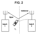
- Figure 2 illustrates an example where a UE may cause interference in a neighboring cell/sector (hereinafter collectively referred to as a cell).
- UE T1 is served by Node-B 1 and generates interference to Node-B 2.
- UE T1 has a strong shadow fade to Node-B 2
- Another example is the case of a nonhomogeneous deployment in which Node-B 2 has a much larger cell radius, in which case UE T1 should be allowed to transmit at higher power levels.
- the open loop fractional power control method may be modified as follows: the target SINR may be set as a function of the path loss difference between the serving cell/ serving Node B and the strongest neighbor cell/neighbor Node B.
- the target SINR may be set as a function of the path loss difference between the serving cell/ serving Node B and the strongest neighbor cell/neighbor Node B.
- PathLoss_Diff_dB 10 * log 10 DL_Rx_PilotPower_ServingCell / DL_Rx_PilotPower_StrongestNeighborCell
- DL_Rx_PilotPower_ServingCell is the received downlink pilot power from the serving Node B
- DL_Rx_PilotPower_StrongestNeighborCell is the received downlink pilot power from the strongest neighbor Node B.
- the quantity in parenthesis is simply referred to as the downlink pilot power ratio (PPR).
- the positive slope parameter B specifies how quickly the target SINR increases as the UE moves towards the cell interior, and hence controls the fairness of the power control scheme.
- Max_Target_SINR_dB is the maximum allowable target SINR.
- Figure 3 illustrates a graph of the target SINR versus path loss for first and second example sets of intercept parameter A and the fairness parameter B.
- Figure 3 is an illustration of increasing target SINR as the path loss difference between the serving cell and the strongest non-serving cell increases (i.e., as the UE moves towards the interior of the cell).
- Figure 3 includes a first curve represented by diamonds for when the intercept parameter is -5 and the fairness parameter is 0.5, and includes a second curve represented by squares for when the intercept parameter is -5 and the fairness parameter is 0.7.
- larger values of the fairness parameter B are more aggressive at increasing the target SINR for high geometry users.
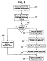
- Figure 4 illustrates a flow chart of the process performed by a UE in determining the transmit power spectral density level, which will also be referred to herein as the reverse link power.
- the UE measures the received downlink pilot power from the current serving station (e.g., the Node B currently handing the communication needs of the UE). Often times, this is expressed as measuring the received downlink pilot power from the serving sector or cell. This measurement may be made on the order of every 100ms - 200ms, and the received pilot power will be averaged over this interval so as to average out the affects of fast fading.
- the current serving station e.g., the Node B currently handing the communication needs of the UE.
- this is expressed as measuring the received downlink pilot power from the serving sector or cell. This measurement may be made on the order of every 100ms - 200ms, and the received pilot power will be averaged over this interval so as to average out the affects of fast fading.
- the UE measures the received downlink pilot power from any other neighboring station (e.g., Node Bs with coverage areas (cell or sector) adjacent to the serving Node B) within its receiving range. Often times, this is expressed as measuring the received downlink pilot power from the neighboring sector or cell. This measurement may be made on the order of every 100ms - 200ms, and the received pilot power will be averaged over this interval so as to average out the affects of fast fading.
- any other neighboring station e.g., Node Bs with coverage areas (cell or sector) adjacent to the serving Node B
- this is expressed as measuring the received downlink pilot power from the neighboring sector or cell. This measurement may be made on the order of every 100ms - 200ms, and the received pilot power will be averaged over this interval so as to average out the affects of fast fading.
- PPR pilot power ratio
- the serving station broadcasts fractional power control parameters A, B, uplink interference, and Max_Target_SINR_dB on a broadcast channel such that all UEs being served by this station can decode the parameters. Accordingly, in step S70, the UE obtains these values. However, it will be appreciated the obtaining these values may occur before the process or concurrently with any step of the process.
- step S80 the UE computes the modified target SINR according to expression (5).
- Scheduling is frequency selective based on uplink CQI pilot, only localized subcarrier allocations are used without any frequency hopping.
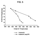
- Figure 5 illustrates the performance of the power control schemes for the assumptions listed in Table 1, presented as cell edge rate (defined as the 5% CDF user throughput) vs. average cell throughput. Note that the performance of fractional power control significantly improves by making use of the difference in path loss from the serving cell to the strongest neighbor cell, as compared to the case of using only the path loss to the serving cell alone. That is, for a given cell edge rate, a higher cell throughput can be obtained; or for a given cell throughput, a higher cell edge rate can be obtained.
- Open loop fractional power control using the path loss difference between the serving cell and the strongest neighbor cell provides significantly improved performance as compared to using the path loss from the serving cell alone
Description
- Example embodiments of the present invention relate generally to reverse link power control in a wireless communications network.
- A cellular communications network typically includes a variety of communication nodes coupled by wireless or wired connections and accessed through different types of communications channels. Each of the communication nodes includes a protocol stack that processes the data transmitted and received over the communications channels. Depending on the type of communications system, the operation and configuration of the various communication nodes can differ and are often referred to by different names. Such communications systems include, for example, a Code Division Multiple Access 2000 (CDMA2000) system and Universal Mobile Telecommunications System (UMTS).
- UMTS is a wireless data communication and telephony standard which describes a set of protocol standards. UMTS sets forth the protocol standards for the transmission of voice and data between a base station (BS) or Node B and a mobile or User Equipment (UE). UMTS systems typically include multiple radio network controllers (RNCs). The RNC in UMTS networks provides functions equivalent to the Base Station Controller (BSC) functions in GSM/GPRS networks. However, RNCs may have further capabilities including, for example, autonomously managing handovers without involving mobile switching centers (MSCs) and Serving General Packet Radio Service (GPRS) Support Nodes (SGSNs). The Node B is responsible for air interface processing and some Radio Resource Management functions. The Node B in UMTS networks provides functions equivalent to the Base Transceiver Station (BTS) in GSM/GPRS networks. Node Bs are typically physically co-located with existing GSM base transceiver station (BTS) to reduce the cost of UMTS implementation and minimize planning consent restrictions.
-
Figure 1 illustrates aconventional communication system 100 operating in accordance with UMTS protocols. Referring toFigure 1 , thecommunication system 100 may include a number of Node Bs such asNode Bs - The Node Bs are connected to an RNC such as
RNCs SGSN 140. The RNC handles certain call and data handling functions, such as, as discussed above, autonomously managing handovers without involving MSCs and SGSNs. The MSC/SGSN 140 handles routing calls and/or data to other elements (e.g.,RNCs 130/132 and NodeBs 120/122/124) in the network or to an external network. Further illustrated inFigure 1 are conventional interfaces Uu, Iub, Iur and Iu between these elements. - A fractional power control scheme has been proposed for controlling the mobile or UE transmission power on the reverse link of the 3GPP LTE standard. This open loop fraction power control technique proposes setting the UE transmit power spectral density such that a fraction of the path loss (including shadowing) may be compensated. Namely, the UE transmit power spectral density TxPSD_dBm may be established as:

Max_TxPSD_dBm is the maximum UE transmit power spectral density (power per tone), which is a function of the UE power class and the assigned transmission bandwidth (for example, the 21 dBm UE power class assigned a single resource unit of 12 subcarriers will have a maximum transmit power per tone of 10.21 dBm);
UL_Interference_dBm is the reverse or uplink interference measured by a Node B serving the UE (typically, this the Node B determines this as total received energy minus the energy received from UEs being served by the Node B), and is reported to the UE, for example, over a control channel;
PathLoss_dB is the path loss between the Node B and the UE; and
Target_SINR_dB is the target signal-to-noise ratio (SINR) per antenna per tone. The fractional power control scheme available in the literature sets the target SINR to be a function of the path loss to the serving cell as follows:

- Note that if B = O, there is no compensation for the path loss and all UEs transmit with the same transmit power spectral density (possible maximum power), which results in high interference levels and poor cell edge performance. If B = 1, this is traditional slow power control in which the path loss is fully compensated and all UEs are received with the same SINR. This results in poor spectral efficiency. By setting O < B < 1, only a fraction of the path loss is compensated, which provides flexibility in balancing spectral efficiency and cell edge performance.
- From Texas Instruments "A Method for Uplink Open Loop Power Control Based on Signal Strength Measurements from Multiple Cells/Sectors", 3GPP TSG RAN WG1 Meeting #46, Tallinn, Estonia, August 28 - September 1, 2006, a method for apower control is knwon, in which a UE (user equipment) measures signal strength from the serving cell / sector, and from the nearby non - serving cells/sectors. If the propagation loss to all non - serving cells/sectors is substantial, then this particular user is allowed to transmit with higher power.
- It is a task of the invention, to further improve such a power control in a way that it takes even better into consideration the interference an UE introduces to a neighbor cell/sector.
- At least one problem with open loop fractional power control as described above is that it does not directly take into consideration the amount of interference a UE will generate to a neighbor cell/ sector. At least one embodiment of the present invention makes use of the level of interference a UE will generate to its neighbor cell/sector in determining the transmit power spectral density for the UE. Accordingly, advantages include allowing for smaller variance in the interference distribution, higher throughput, and/or etc.
- A reverse link transmission power for a user equipment is determined based on a first path loss and a second path loss. The first path loss is path loss between a serving station and the user equipment, and the serving station serves the communication needs of the user equipment. The second path loss is path loss between a neighboring station and the user equipment, and the neighboring station neighbors the serving station.
- User equipment measures received downlink power from a serving station. The serving station serves the communication needs of the user equipment. The user equipment also measures received downlink power from a neighboring station. The neighboring station neighbors the serving station. The user equipment determines a reverse link transmission power based on the measured received downlink power from the serving station divided by the measured received downlink power from the neighboring station.
- The present invention will become more fully understood from the detail description given herein below and the accompanying drawings which are given by way of illustration only, wherein like reference numerals designate corresponding parts in the various drawings, and wherein:
-
Figure 1 illustrates aconventional communication system 100 operating in accordance with UMTS protocols; -
Figure 2 illustrates an example where a UE may cause interference in a neighboring cell; -
Figure 3 illustrates a graph of the target SINR versus path loss for first and second example sets of intercept parameter and the fairness parameter; -
Figure 4 illustrates a flow chart of the process performed by a UE in determining the transmit power spectral density according to an embodiment of the present invention; and -
Figure 5 illustrates the performance of the power control schemes for the assumptions listed in Table 1 below, presented as cell edge rate (defined as the 5% CDF user throughput) vs. average cell throughput. - Example embodiments of the present invention will be described with respect to the UMTS system illustrated in
Figure 1 . However, it will be understood that the present invention is not limited to this system or to UMTS systems. - As discussed above, one problem with open loop fractional power is that it does not directly take into consideration the amount of interference a UE will generate to a neighbor cell/sector. For example,
Figure 2 illustrates an example where a UE may cause interference in a neighboring cell/sector (hereinafter collectively referred to as a cell). InFigure 2 , UE T1 is served by Node-B 1 and generates interference to Node-B 2. However, if UE T1 has a strong shadow fade to Node-B 2, then it should be allowed to transmit at a higher transmit power spectral density as compared to the case when UE T1 has a small shadow fade to Node-B 2. Another example is the case of a nonhomogeneous deployment in which Node-B 2 has a much larger cell radius, in which case UE T1 should be allowed to transmit at higher power levels. - According to one embodiment, the open loop fractional power control method may be modified as follows: the target SINR may be set as a function of the path loss difference between the serving cell/ serving Node B and the strongest neighbor cell/neighbor Node B. For example, one embodiment determines this modified target SINR, Modified_Target_SINR_dB, as follows:

where PathLoss_Diff_dB is the difference in path loss (including shadowing) between the strongest neighbor Node B and the current serving Node B. This measurement may easily be made by determining the ratio of the received downlink pilot power measurements as follows:
where DL_Rx_PilotPower_ServingCell is the received downlink pilot power from the serving Node B and DL_Rx_PilotPower_StrongestNeighborCell is the received downlink pilot power from the strongest neighbor Node B. The quantity in parenthesis is simply referred to as the downlink pilot power ratio (PPR). In equation (4), the intercept parameter A specifies the target SINR at the "cell edge" (i.e., when PathLoss_Diff_dB = 0). The positive slope parameter B specifies how quickly the target SINR increases as the UE moves towards the cell interior, and hence controls the fairness of the power control scheme. Max_Target_SINR_dB is the maximum allowable target SINR. -
Figure 3 illustrates a graph of the target SINR versus path loss for first and second example sets of intercept parameter A and the fairness parameter B. In particular,Figure 3 is an illustration of increasing target SINR as the path loss difference between the serving cell and the strongest non-serving cell increases (i.e., as the UE moves towards the interior of the cell).Figure 3 includes a first curve represented by diamonds for when the intercept parameter is -5 and the fairness parameter is 0.5, and includes a second curve represented by squares for when the intercept parameter is -5 and the fairness parameter is 0.7. As shown, larger values of the fairness parameter B are more aggressive at increasing the target SINR for high geometry users. -
Figure 4 illustrates a flow chart of the process performed by a UE in determining the transmit power spectral density level, which will also be referred to herein as the reverse link power. As shown, in step S10, the UE measures the received downlink pilot power from the current serving station (e.g., the Node B currently handing the communication needs of the UE). Often times, this is expressed as measuring the received downlink pilot power from the serving sector or cell. This measurement may be made on the order of every 100ms - 200ms, and the received pilot power will be averaged over this interval so as to average out the affects of fast fading. Then, in step S20, the UE measures the received downlink pilot power from any other neighboring station (e.g., Node Bs with coverage areas (cell or sector) adjacent to the serving Node B) within its receiving range. Often times, this is expressed as measuring the received downlink pilot power from the neighboring sector or cell. This measurement may be made on the order of every 100ms - 200ms, and the received pilot power will be averaged over this interval so as to average out the affects of fast fading. - In step S30, the UE determines whether any neighboring stations were detected in step S20. If not, in step S40, the UE sets a modified target SINR to a maximum permitted value (see step S70). However, if a neighbor station was detected in step S20, the UE determines in step S50 the strongest non-serving neighbor as the one with the highest received downlink pilot power detected in step S20. In step S60, the UE computes the pilot power ratio (PPR) as the received downlink pilot power from the serving sector divided by the received downlink pilot power from the strongest non-serving sector. Then, the UE determines the path loss difference in dB scale as PathLoss_Diff_dB = 10*log10(PPR).
- The serving station broadcasts fractional power control parameters A, B, uplink interference, and Max_Target_SINR_dB on a broadcast channel such that all UEs being served by this station can decode the parameters. Accordingly, in step S70, the UE obtains these values. However, it will be appreciated the obtaining these values may occur before the process or concurrently with any step of the process.
- Then, in step S80, the UE computes the modified target SINR according to expression (5).
- After either step S40 or S80, the UE, in step S90 determines the transmit power spectral density according to expression (1) using the modified target SINR as shown in expression (6) below:

- Using the system simulation assumptions listed in Table 1 below, the performance of fractional power control using path loss only (as in equation 1) and using the pilot power ratio measurement (as in equation 6) were simulated. For the fractional power control schemes, a range of values for B was chosen to illustrate the tradeoff between cell throughput and cell edge rates. For each value of B, A was chosen in order to get a median IoT (interference over thermal) operating point of 4.5 dB. In practice, the desired IoT operating point may be dictated by link budget requirements of reverse link control channels. In both of the fractional power control cases, a maximum target SINR of 25 dB was used.
Table 1: System Simulation Assumptions Parameter Assumption Transmission Bandwidth 5 MHz FDD Cellular Layout Hexagonal grid, 19 cell sites, 3 sectors per site Inter-site distance 2500 meters Losses (cable loss, body loss, etc.) 7 dB Distance-dependent path loss COST 231 HATA model L=139.6 + 35.7log10(.R), R in kilometers Lognormal Shadowing Similar to UMTS 30.03, B 1.4.1.4 Shadowing standard deviation 8 dB Correlation distance of Shadowing 50 m Shadowing correlation Between cells 0.5 Between sectors 1.0 Antenna pattern (horizontal) (For 3-sector cell sites with fixed antenna patterns) Kathrein antenna pattern, 65 degree beamwidth, 17.1 dBi antenna gain Carrier Frequency / Bandwidth 1.9 GHz / 5 MHz Channel model GSM TU, 3 km/hr Total BS TX power (Ptotal) 43dBm UE power class 21dBm (125mW). Inter-cell Interference Modelling Explicit modelling (all cells occupied by UEs) Antenna Bore-sight points toward flat side of cell (for 3-sector sites with fixed antenna patterns) 
Users dropped uniformly in entire cell 
Minimum distance between UE and cell >= 35 meters MCS Levels in Scheduler QPSK R=1/8, ¼, 1/3, ½, 2/3, ¾ 16 QAM R=1/2, 2/3, ¾, 7/8 HARQ Max of 8 Tx, Target 20% BLER on first Tx.HARQ RIT = 5ms Num HARQ Processes = 10 Reuse scheme Reuse-1, no fractional frequency reuse or interference avoidance applied Num UEs Per Cell 10 Traffic Model Full Buffer Scheduling scheme Proportional Fair, 500ms time constant. Scheduling is frequency selective based on uplink CQI pilot, only localized subcarrier allocations are used without any frequency hopping. Modeling of Channel Estimation . Non-ideal, assumes one-shot channel estimation over TTI (= 1 ms) L1/L2 Control Signaling Modeled No Link to System Mapping Effective Code Rate Method Open loop fractional power control assumptions Ideal measurement of path loss (including shadowing) -
Figure 5 illustrates the performance of the power control schemes for the assumptions listed in Table 1, presented as cell edge rate (defined as the 5% CDF user throughput) vs. average cell throughput. Note that the performance of fractional power control significantly improves by making use of the difference in path loss from the serving cell to the strongest neighbor cell, as compared to the case of using only the path loss to the serving cell alone. That is, for a given cell edge rate, a higher cell throughput can be obtained; or for a given cell throughput, a higher cell edge rate can be obtained. - Open loop fractional power control using the path loss difference between the serving cell and the strongest neighbor cell provides significantly improved performance as compared to using the path loss from the serving cell alone
- The invention being thus described, it will be obvious that the same may be varied in many ways. For example, the parameters A and B may be fixed, set by a system operator, updated by a system operator, adapted to change based on factors such as load, time of day, etc. Such variations are not to be regarded as a departure from the invention, and all such modifications are intended to be included within the scope of the invention.
Claims (7)
- A method of reverse link power control, comprising:determining (S90) a reverse link transmission power for a user equipment (105) based on a first path loss and a second path loss, the first path loss being path loss between a serving station (120) and the user equipment (105), the serving station (120) serving the communication needs of the user equipment (105), and the second path loss being path loss between a neighboring station (122) and the user equipment (105), the neighboring station (122) neighboring the serving station (120),measuring (S10) received downlink power from the serving station (120);measuring (S20) received downlink power from the neighboring station (122); the method characterized by:determining (S60) a path loss difference between the first path loss and the second path loss based on the measured received downlink power from the serving station (120) divided by the measured received downlink power from the neighboring station (122); and whereinthe determining a reverse link transmission power step determines the reverse link transmission power based on the determined path loss difference.
- The method of claim 1, wherein the neighboring station (122) is a neighboring station with a greatest received downlink power at the user equipment.
- The method of claim 1, further comprising:determining (S80) a target signal-to-noise ratio (SINR) for the user equipment (105) based on the determined path loss difference; and whereinthe determining a reverse link transmission power step determines the reverse link transmission power based on the determined target SINR.
- The method of claim 3, wherein the determining a target SINR step determines the target SINR based on the determined path loss difference, a first parameter and a second parameter, the first parameter specifies a desired target SINR at an edge of a coverage area of the serving station (120), and the second parameter specifies how quickly the target SINR increases as the user equipment moves towards an interior of the coverage area.
- The method of claim 4, wherein the determining a target SINR step determines the target SINR as follows:target SINR=min(A+B*(PathLoss_Diff), Max_Target-SINR)where the PathLoss_Diff is the path loss difference. A is the first parameter, B is the second parameter, and Max_Target_SINR is a maximum target SINR.
- The method of claim 5, wherein the determining a reverse link transmission power step determines the reverse link transmission power as follows:reverse link transmission power=min(maximum transmission power, target SINR+first path loss+UL_Interference)where the UL_interterence is uplink interference at the serving station.
- The method of claim 3, wherein the determining a reverse link transmission power step determines the reverse link transmission power based on the path loss difference and uplink interference at the serving station (120).
Applications Claiming Priority (2)
| Application Number | Priority Date | Filing Date | Title |
|---|---|---|---|
| US11/650,984 US7917164B2 (en) | 2007-01-09 | 2007-01-09 | Reverse link power control |
| PCT/US2008/000188 WO2008085936A2 (en) | 2007-01-09 | 2008-01-07 | Reverse link power control |
Publications (2)
| Publication Number | Publication Date |
|---|---|
| EP2102996A2 EP2102996A2 (en) | 2009-09-23 |
| EP2102996B1 true EP2102996B1 (en) | 2013-11-27 |
Family
ID=39496027
Family Applications (1)
| Application Number | Title | Priority Date | Filing Date |
|---|---|---|---|
| EP08713028.2A Not-in-force EP2102996B1 (en) | 2007-01-09 | 2008-01-07 | Reverse link power control |
Country Status (5)
| Country | Link |
|---|---|
| US (1) | US7917164B2 (en) |
| EP (1) | EP2102996B1 (en) |
| JP (1) | JP5281017B2 (en) |
| CN (1) | CN101584129B (en) |
| WO (1) | WO2008085936A2 (en) |
Families Citing this family (74)
| Publication number | Priority date | Publication date | Assignee | Title |
|---|---|---|---|---|
| US6807405B1 (en) | 1999-04-28 | 2004-10-19 | Isco International, Inc. | Method and a device for maintaining the performance quality of a code-division multiple access system in the presence of narrow band interference |
| US8452316B2 (en) | 2004-06-18 | 2013-05-28 | Qualcomm Incorporated | Power control for a wireless communication system utilizing orthogonal multiplexing |
| US7594151B2 (en) * | 2004-06-18 | 2009-09-22 | Qualcomm, Incorporated | Reverse link power control in an orthogonal system |
| US7197692B2 (en) * | 2004-06-18 | 2007-03-27 | Qualcomm Incorporated | Robust erasure detection and erasure-rate-based closed loop power control |
| US8942639B2 (en) | 2005-03-15 | 2015-01-27 | Qualcomm Incorporated | Interference control in a wireless communication system |
| US8848574B2 (en) | 2005-03-15 | 2014-09-30 | Qualcomm Incorporated | Interference control in a wireless communication system |
| US8712422B1 (en) | 2005-05-18 | 2014-04-29 | Sprint Spectrum L.P. | Dynamic allocation of access channels based on access channel occupancy in a cellular wireless communication system |
| JP5430938B2 (en) | 2005-10-27 | 2014-03-05 | クゥアルコム・インコーポレイテッド | Method and apparatus for estimating reverse link loading in a wireless communication system |
| CN101512935B (en) * | 2006-07-27 | 2013-10-30 | 艾利森电话股份有限公司 | Layered broadcast transmission through multiple transmitters |
| US8670777B2 (en) | 2006-09-08 | 2014-03-11 | Qualcomm Incorporated | Method and apparatus for fast other sector interference (OSI) adjustment |
| US20080117849A1 (en) * | 2006-09-08 | 2008-05-22 | Qualcomm Incorporated | Method and apparatus for interaction of fast other sector interference (osi) with slow osi |
| US8442572B2 (en) * | 2006-09-08 | 2013-05-14 | Qualcomm Incorporated | Method and apparatus for adjustments for delta-based power control in wireless communication systems |
| US7711057B2 (en) * | 2007-01-17 | 2010-05-04 | C & P Technologies, Inc. | Apparatus and method for providing energy—bandwidth tradeoff and waveform design in interference and noise |
| US7720132B2 (en) * | 2007-01-17 | 2010-05-18 | C&P Technologies, Inc. | Energy—bandwidth tradeoff and transmit waveform design using interference and noise whitening method |
| EP2127163B1 (en) * | 2007-03-26 | 2015-07-22 | Telefonaktiebolaget LM Ericsson (publ) | A method and a device for finding imperfections in an rf path |
| US8909279B2 (en) * | 2007-08-10 | 2014-12-09 | Qualcomm Incorporated | Adaptation of transmit power for neighboring nodes |
| US7970361B2 (en) * | 2007-11-28 | 2011-06-28 | Telefonaktiebolaget L M Ericsson (Publ) | Frequency band recognition methods and apparatus |
| EP2083524B1 (en) * | 2008-01-22 | 2011-11-30 | TELEFONAKTIEBOLAGET LM ERICSSON (publ) | Method, computer program receiver, as well as apparatus, for determining a channel quality index |
| US8504091B2 (en) * | 2008-02-01 | 2013-08-06 | Qualcomm Incorporated | Interference mitigation for control channels in a wireless communication network |
| KR101507176B1 (en) * | 2008-07-08 | 2015-03-31 | 엘지전자 주식회사 | Method for uplink power control in the wireless communication system |
| US20110116408A1 (en) * | 2008-07-08 | 2011-05-19 | Dong Cheol Kim | Substrate conveying device |
| US8385483B2 (en) | 2008-11-11 | 2013-02-26 | Isco International, Llc | Self-adaptive digital RF bandpass and bandstop filter architecture |
| US8219136B2 (en) * | 2009-02-09 | 2012-07-10 | Intel Corporation | Techniques to determine transmitter power |
| US8588178B2 (en) * | 2009-03-19 | 2013-11-19 | Qualcomm Incorporated | Adaptive association and joint association and resource partitioning in a wireless communication network |
| CN102396270A (en) * | 2009-03-27 | 2012-03-28 | 华为技术有限公司 | Method and device for performing emission power control in multi-carrier system |
| EP2282591B1 (en) * | 2009-07-01 | 2012-09-12 | Ntt Docomo, Inc. | Mobile and base station transceiver apparatus for communicating |
| US8331937B2 (en) * | 2009-08-17 | 2012-12-11 | Motorola Mobility Llc | Mitigation of uplink interference from wireless communication device connected to a micro cell |
| US8422956B2 (en) * | 2009-08-17 | 2013-04-16 | Motorola Mobility Llc | Mitigation of uplink interference from wireless communication device connected to micro cell |
| US8340593B2 (en) * | 2009-11-10 | 2012-12-25 | Intel Corporation | Techniques to control uplink power |
| CN102076062B (en) * | 2009-11-20 | 2015-03-11 | 华为技术有限公司 | Uplink transmit power control parameter acquisition method, eNodeB and user equipment |
| US9031599B2 (en) | 2009-12-08 | 2015-05-12 | Futurewei Technologies, Inc. | System and method for power control |
| US8515474B2 (en) * | 2010-01-20 | 2013-08-20 | Futurewei Technologies, Inc. | System and method for scheduling users on a wireless network |
| US8437794B2 (en) * | 2010-01-28 | 2013-05-07 | Alcatel Lucent | Methods of determining uplink target signal-to-interfence-and-noise ratios and systems thereof |
| EP2556704B1 (en) * | 2010-04-09 | 2017-06-07 | Telefonaktiebolaget LM Ericsson (publ) | Method and arrangement in a wireless network for determining an uplink received power target value |
| US9002397B2 (en) | 2010-06-29 | 2015-04-07 | Qualcomm Incorporated | Method and apparatus for device transmit power capping in wireless communications |
| JP5364048B2 (en) * | 2010-07-07 | 2013-12-11 | 株式会社エヌ・ティ・ティ・ドコモ | Base station apparatus and method |
| JP5427139B2 (en) | 2010-07-29 | 2014-02-26 | 株式会社日立製作所 | Base station and cellular radio communication system |
| US9055544B2 (en) * | 2010-11-02 | 2015-06-09 | Alcatel Lucent | Methods of setting maximum output power for user equipment and reporting power headroom, and the user equipment |
| US9749965B2 (en) | 2010-11-02 | 2017-08-29 | Telefonaktiebolaget L M Ericsson | Method for uplink fractional transmit power control |
| US9445424B2 (en) * | 2010-11-10 | 2016-09-13 | Telefonaktiebolaget Lm Ericsson (Publ) | Radio base station and method for scheduling radio resources for user equipment |
| CN102143568B (en) * | 2010-11-26 | 2015-02-04 | 华为技术有限公司 | Power control method and base station |
| US9420543B2 (en) * | 2010-12-10 | 2016-08-16 | Qualcomm Incorporated | Control of transmission power on high-speed dedicated physical control channel |
| CN102573028A (en) * | 2010-12-16 | 2012-07-11 | 中兴通讯股份有限公司 | Open loop power controlling method and system |
| CN102056178B (en) * | 2011-01-17 | 2013-08-21 | 新邮通信设备有限公司 | Interference coordination method among cells and a basestation |
| WO2012101482A1 (en) * | 2011-01-26 | 2012-08-02 | Nokia Corporation | Apparatus and method for allocating communication resources in a communication system |
| US9554338B2 (en) * | 2011-02-18 | 2017-01-24 | Qualcomm Incorporated | Apparatus, method, and system for uplink control channel reception in a heterogeneous wireless communication network |
| CN103444105A (en) * | 2011-03-30 | 2013-12-11 | Nec卡西欧移动通信株式会社 | Receiving device, receiving method, and computer program |
| CN102932891A (en) * | 2011-03-31 | 2013-02-13 | 北京新岸线无线技术有限公司 | Method and device for control upstream access open loop power |
| KR20140002043A (en) * | 2011-04-15 | 2014-01-07 | 알까뗄 루슨트 | Method and device for controlling uplink power |
| CN102811478B (en) * | 2011-05-31 | 2016-03-30 | 华为技术有限公司 | A kind of path loss compensation method and base station and subscriber equipment |
| US9414327B2 (en) * | 2011-06-06 | 2016-08-09 | Alcatel Lucent | Method and apparatus of fractional power control in wireless communication networks |
| CN106102150B (en) | 2011-08-17 | 2019-08-13 | 华为技术有限公司 | The method and terminal of terminal transmission uplink signal |
| US8995388B2 (en) | 2012-01-19 | 2015-03-31 | Futurewei Technologies, Inc. | Systems and methods for uplink resource allocation |
| US9338807B2 (en) | 2012-03-19 | 2016-05-10 | Futurewei Technologies, Inc. | System and method for direct mobile communications power control |
| WO2014097352A1 (en) * | 2012-12-19 | 2014-06-26 | 富士通株式会社 | Radio communication method, radio communication system, radio station and radio terminal |
| US9319916B2 (en) | 2013-03-15 | 2016-04-19 | Isco International, Llc | Method and appartus for signal interference processing |
| JP6110016B2 (en) * | 2013-04-26 | 2017-04-05 | アルカテル−ルーセント | Method and apparatus for interference-based uplink fractional power control |
| CN104219750B (en) * | 2013-06-03 | 2018-03-23 | 普天信息技术研究院有限公司 | A kind of close-loop power controlling method |
| CN104349437B (en) * | 2013-08-09 | 2018-10-19 | 上海诺基亚贝尔股份有限公司 | Method for inhibiting interference and user equipment |
| WO2015028723A1 (en) * | 2013-08-29 | 2015-03-05 | Cassidian Sas | Method for defining parameter values for controlling the transmission power of a piece of user equipment |
| EP3050367B1 (en) * | 2013-11-14 | 2018-01-10 | Huawei Technologies Co., Ltd. | Methods and nodes in a wireless communication network |
| US9585103B2 (en) * | 2014-01-30 | 2017-02-28 | Qualcomm Incorporated | Techniques for controlling transmission power in shared radio frequency spectrum |
| CN103945513B (en) * | 2014-04-01 | 2018-06-01 | 大唐移动通信设备有限公司 | Poewr control method and device |
| US9775116B2 (en) | 2014-05-05 | 2017-09-26 | Isco International, Llc | Method and apparatus for increasing performance of communication links of cooperative communication nodes |
| CN104168635B (en) * | 2014-08-05 | 2018-05-01 | 大唐移动通信设备有限公司 | A kind of ascending power control method and device |
| EP3192302B1 (en) * | 2014-09-10 | 2018-12-26 | Telefonaktiebolaget LM Ericsson (publ) | Method and network node for obtaining nominal power and pathloss compensation factor of a power control process |
| WO2016178778A1 (en) | 2015-05-04 | 2016-11-10 | Isco International, Llc | Method and apparatus for increasing performance of communication paths for communication nodes |
| US10359497B1 (en) * | 2016-04-07 | 2019-07-23 | Sprint Communications Company L.P. | Directional antenna orientation optimization |
| WO2017210056A1 (en) | 2016-06-01 | 2017-12-07 | Isco International, Llc | Method and apparatus for performing signal conditioning to mitigate interference detected in a communication system |
| CN107623942B (en) * | 2016-07-14 | 2022-06-17 | 中兴通讯股份有限公司 | Method and device for adjusting uplink power |
| CN107682922B (en) * | 2016-08-01 | 2021-01-05 | 中国电信股份有限公司 | Method and system for determining uplink signal interference noise ratio target value |
| US10298279B2 (en) | 2017-04-05 | 2019-05-21 | Isco International, Llc | Method and apparatus for increasing performance of communication paths for communication nodes |
| US10812121B2 (en) | 2017-08-09 | 2020-10-20 | Isco International, Llc | Method and apparatus for detecting and analyzing passive intermodulation interference in a communication system |
| US10284313B2 (en) | 2017-08-09 | 2019-05-07 | Isco International, Llc | Method and apparatus for monitoring, detecting, testing, diagnosing and/or mitigating interference in a communication system |
Family Cites Families (19)
| Publication number | Priority date | Publication date | Assignee | Title |
|---|---|---|---|---|
| US5491837A (en) * | 1994-03-07 | 1996-02-13 | Ericsson Inc. | Method and system for channel allocation using power control and mobile-assisted handover measurements |
| US6628956B2 (en) * | 1999-03-15 | 2003-09-30 | Telefonaktiebolaget Lm Ericsson (Publ) | Adaptive power control in a radio communications systems |
| KR100619223B1 (en) * | 2001-07-24 | 2006-09-07 | 가부시키가이샤 엔티티 도코모 | Transmission power control apparatus and method in a mobile communication system, mobile station, and communication apparatus |
| JP4343917B2 (en) * | 2001-07-24 | 2009-10-14 | 株式会社エヌ・ティ・ティ・ドコモ | Transmission power control apparatus and method, mobile station and communication apparatus in mobile communication system |
| US6983166B2 (en) * | 2001-08-20 | 2006-01-03 | Qualcomm, Incorporated | Power control for a channel with multiple formats in a communication system |
| US7031742B2 (en) | 2002-02-07 | 2006-04-18 | Qualcomm Incorporation | Forward and reverse link power control of serving and non-serving base stations in a wireless communication system |
| US7453861B2 (en) * | 2002-08-02 | 2008-11-18 | At&T Corp | System and method for estimating interference in a packet-based wireless network |
| US7907910B2 (en) * | 2004-08-02 | 2011-03-15 | Intel Corporation | Method and apparatus to vary power level of training signal |
| US20090143070A1 (en) * | 2005-01-20 | 2009-06-04 | Kodo Shu | Supporting an Allocation of Radio Resources |
| KR100957314B1 (en) * | 2005-02-16 | 2010-05-12 | 삼성전자주식회사 | System and method for controlling uplink traffic load in a cellular wireless mobile communication system |
| US7702351B2 (en) | 2005-02-17 | 2010-04-20 | Qualcomm Incorporated | System and method for global power control |
| KR20070059666A (en) * | 2005-12-07 | 2007-06-12 | 삼성전자주식회사 | Apparatus and method for power controlling of time division duplex telecommunication system |
| US7813753B2 (en) * | 2006-02-27 | 2010-10-12 | Qualcomm Incorporated | Power control in communication systems |
| KR100964546B1 (en) * | 2006-07-04 | 2010-06-21 | 삼성전자주식회사 | Method and system for controlling in a communication system |
| WO2008003815A1 (en) * | 2006-07-07 | 2008-01-10 | Nokia Corporation | Improved radio resource allocation mechanism |
| CN101518144A (en) * | 2006-09-14 | 2009-08-26 | 交互数字技术公司 | Method and apparatus for assigning cell and resource blocks through interference optimization |
| US8073481B2 (en) * | 2006-11-01 | 2011-12-06 | Qualcomm Incorporated | Interference and power control for wireless communication |
| US20080188260A1 (en) * | 2007-02-02 | 2008-08-07 | Motorola, Inc. | Method and apparatus for uplink power control in a communication system |
| US8442529B2 (en) * | 2007-12-13 | 2013-05-14 | Qualcomm Incorporated | Methods and apparatus for making handoff decisions in access terminals capable of operating at different times in best effort and QoS modes of traffic operation |
-
2007
- 2007-01-09 US US11/650,984 patent/US7917164B2/en not_active Expired - Fee Related
-
2008
- 2008-01-07 CN CN200880001878XA patent/CN101584129B/en not_active Expired - Fee Related
- 2008-01-07 WO PCT/US2008/000188 patent/WO2008085936A2/en active Application Filing
- 2008-01-07 EP EP08713028.2A patent/EP2102996B1/en not_active Not-in-force
- 2008-01-07 JP JP2009545574A patent/JP5281017B2/en not_active Expired - Fee Related
Also Published As
| Publication number | Publication date |
|---|---|
| US7917164B2 (en) | 2011-03-29 |
| CN101584129A (en) | 2009-11-18 |
| CN101584129B (en) | 2013-03-27 |
| JP5281017B2 (en) | 2013-09-04 |
| WO2008085936A2 (en) | 2008-07-17 |
| US20080166976A1 (en) | 2008-07-10 |
| EP2102996A2 (en) | 2009-09-23 |
| JP2010516184A (en) | 2010-05-13 |
| WO2008085936A3 (en) | 2008-09-12 |
Similar Documents
| Publication | Publication Date | Title |
|---|---|---|
| EP2102996B1 (en) | Reverse link power control | |
| EP2359619B1 (en) | Method and apparatus of communication | |
| US9467864B2 (en) | Method and apparatus of spectrum utilization in a wireless cellular environment | |
| EP2663134B1 (en) | A method and base station to control access point transmit power | |
| EP2560426B1 (en) | Wireless communication system, high-power base station, low-power base station, and communication control method | |
| WO2011136083A1 (en) | Wireless communication system, radio base station, and communication control method | |
| US8880088B2 (en) | Signalling for interference management in HETNETs | |
| US8437794B2 (en) | Methods of determining uplink target signal-to-interfence-and-noise ratios and systems thereof | |
| EP2991413A1 (en) | Method and apparatus for uplink fractional power control based on interference | |
| KR20190025518A (en) | System and method for beam transmission power adjustment for inter-cell interference control | |
| US20050105492A1 (en) | Method and arrangement for allocation the quantity of a channel to a mobile station as a function of the measured quality | |
| US10390253B2 (en) | Network node and a method performed thereby for congestion control of a radio base station | |
| WO2013127061A1 (en) | Inter-cell interference mitigation | |
| KR101162972B1 (en) | Reverse link power control | |
| Safjan et al. | Automatic methods for HetNet uplink power control optimization under fractional load | |
| KR101584960B1 (en) | Methods and apparatus for controlling interference based on information exchange between base stations in communication system | |
| Turkka et al. | Performance of LTE SON uplink load balancing in non-regular network | |
| Castro-Hernandez et al. | A distributed load balancing algorithm for LTE/LTE-A heterogeneous networks | |
| Agrawal et al. | Interference penalty algorithm (IPA) for inter-cell interference co-ordination in LTE uplink | |
| Lalam et al. | Adaptive downlink power control for HSDPA femtocells | |
| Xu et al. | Performance of macro-pico heterogeneous networks based on LTE-advanced | |
| Aberra | Performance Evaluation of 6-Sector Site and Small Cell for Addis Ababa UMTS Deployment Scenario | |
| Ali et al. | Cell edge detection based interference avoidance scheme for closed mode lte femtocells | |
| Danburam et al. | Analysis on energy efficient traffic load balancing in downlink LTE-advance heterogeneous network | |
| Liu et al. | The Study of Two Dimensional Cross-Tier Interference Avoidance in LTE-Advanced Heterogeneous Networks |
Legal Events
| Date | Code | Title | Description |
|---|---|---|---|
| PUAI | Public reference made under article 153(3) epc to a published international application that has entered the european phase |
Free format text: ORIGINAL CODE: 0009012 |
|
| 17P | Request for examination filed |
Effective date: 20090624 |
|
| AK | Designated contracting states |
Kind code of ref document: A2 Designated state(s): AT BE BG CH CY CZ DE DK EE ES FI FR GB GR HR HU IE IS IT LI LT LU LV MC MT NL NO PL PT RO SE SI SK TR |
|
| RIN1 | Information on inventor provided before grant (corrected) |
Inventor name: RAO, ANIL, M. |
|
| DAX | Request for extension of the european patent (deleted) | ||
| 17Q | First examination report despatched |
Effective date: 20110125 |
|
| RAP1 | Party data changed (applicant data changed or rights of an application transferred) |
Owner name: ALCATEL-LUCENT USA INC. |
|
| REG | Reference to a national code |
Ref country code: DE Ref legal event code: R079 Ref document number: 602008028972 Country of ref document: DE Free format text: PREVIOUS MAIN CLASS: H04B0007005000 Ipc: H04W0052100000 |
|
| RIC1 | Information provided on ipc code assigned before grant |
Ipc: H04W 52/10 20090101AFI20130418BHEP Ipc: H04W 52/40 20090101ALI20130418BHEP Ipc: H04W 52/36 20090101ALI20130418BHEP Ipc: H04W 52/24 20090101ALI20130418BHEP Ipc: H04W 52/14 20090101ALI20130418BHEP |
|
| GRAP | Despatch of communication of intention to grant a patent |
Free format text: ORIGINAL CODE: EPIDOSNIGR1 |
|
| INTG | Intention to grant announced |
Effective date: 20130605 |
|
| GRAS | Grant fee paid |
Free format text: ORIGINAL CODE: EPIDOSNIGR3 |
|
| 111Z | Information provided on other rights and legal means of execution |
Free format text: AT BE BG CH CY CZ DE DK EE ES FI FR GB GR HR HU IE IS IT LI LT LU LV MC MT NL NO PL PT RO SE SI SK TR Effective date: 20130410 |
|
| GRAA | (expected) grant |
Free format text: ORIGINAL CODE: 0009210 |
|
| RAP1 | Party data changed (applicant data changed or rights of an application transferred) |
Owner name: ALCATEL LUCENT |
|
| AK | Designated contracting states |
Kind code of ref document: B1 Designated state(s): AT BE BG CH CY CZ DE DK EE ES FI FR GB GR HR HU IE IS IT LI LT LU LV MC MT NL NO PL PT RO SE SI SK TR |
|
| REG | Reference to a national code |
Ref country code: GB Ref legal event code: FG4D |
|
| REG | Reference to a national code |
Ref country code: CH Ref legal event code: EP |
|
| REG | Reference to a national code |
Ref country code: AT Ref legal event code: REF Ref document number: 643115 Country of ref document: AT Kind code of ref document: T Effective date: 20131215 |
|
| REG | Reference to a national code |
Ref country code: IE Ref legal event code: FG4D |
|
| REG | Reference to a national code |
Ref country code: DE Ref legal event code: R096 Ref document number: 602008028972 Country of ref document: DE Effective date: 20140123 |
|
| REG | Reference to a national code |
Ref country code: NL Ref legal event code: VDEP Effective date: 20131127 |
|
| REG | Reference to a national code |
Ref country code: FR Ref legal event code: GC Effective date: 20140306 |
|
| REG | Reference to a national code |
Ref country code: AT Ref legal event code: MK05 Ref document number: 643115 Country of ref document: AT Kind code of ref document: T Effective date: 20131127 |
|
| REG | Reference to a national code |
Ref country code: LT Ref legal event code: MG4D |
|
| PG25 | Lapsed in a contracting state [announced via postgrant information from national office to epo] |
Ref country code: LT Free format text: LAPSE BECAUSE OF FAILURE TO SUBMIT A TRANSLATION OF THE DESCRIPTION OR TO PAY THE FEE WITHIN THE PRESCRIBED TIME-LIMIT Effective date: 20131127 Ref country code: NL Free format text: LAPSE BECAUSE OF FAILURE TO SUBMIT A TRANSLATION OF THE DESCRIPTION OR TO PAY THE FEE WITHIN THE PRESCRIBED TIME-LIMIT Effective date: 20131127 Ref country code: HR Free format text: LAPSE BECAUSE OF FAILURE TO SUBMIT A TRANSLATION OF THE DESCRIPTION OR TO PAY THE FEE WITHIN THE PRESCRIBED TIME-LIMIT Effective date: 20131127 Ref country code: FI Free format text: LAPSE BECAUSE OF FAILURE TO SUBMIT A TRANSLATION OF THE DESCRIPTION OR TO PAY THE FEE WITHIN THE PRESCRIBED TIME-LIMIT Effective date: 20131127 Ref country code: SE Free format text: LAPSE BECAUSE OF FAILURE TO SUBMIT A TRANSLATION OF THE DESCRIPTION OR TO PAY THE FEE WITHIN THE PRESCRIBED TIME-LIMIT Effective date: 20131127 Ref country code: NO Free format text: LAPSE BECAUSE OF FAILURE TO SUBMIT A TRANSLATION OF THE DESCRIPTION OR TO PAY THE FEE WITHIN THE PRESCRIBED TIME-LIMIT Effective date: 20140227 Ref country code: IS Free format text: LAPSE BECAUSE OF FAILURE TO SUBMIT A TRANSLATION OF THE DESCRIPTION OR TO PAY THE FEE WITHIN THE PRESCRIBED TIME-LIMIT Effective date: 20140327 |
|
| PG25 | Lapsed in a contracting state [announced via postgrant information from national office to epo] |
Ref country code: CY Free format text: LAPSE BECAUSE OF FAILURE TO SUBMIT A TRANSLATION OF THE DESCRIPTION OR TO PAY THE FEE WITHIN THE PRESCRIBED TIME-LIMIT Effective date: 20131127 Ref country code: BE Free format text: LAPSE BECAUSE OF FAILURE TO SUBMIT A TRANSLATION OF THE DESCRIPTION OR TO PAY THE FEE WITHIN THE PRESCRIBED TIME-LIMIT Effective date: 20131127 Ref country code: AT Free format text: LAPSE BECAUSE OF FAILURE TO SUBMIT A TRANSLATION OF THE DESCRIPTION OR TO PAY THE FEE WITHIN THE PRESCRIBED TIME-LIMIT Effective date: 20131127 Ref country code: ES Free format text: LAPSE BECAUSE OF FAILURE TO SUBMIT A TRANSLATION OF THE DESCRIPTION OR TO PAY THE FEE WITHIN THE PRESCRIBED TIME-LIMIT Effective date: 20131127 Ref country code: LV Free format text: LAPSE BECAUSE OF FAILURE TO SUBMIT A TRANSLATION OF THE DESCRIPTION OR TO PAY THE FEE WITHIN THE PRESCRIBED TIME-LIMIT Effective date: 20131127 |
|
| PG25 | Lapsed in a contracting state [announced via postgrant information from national office to epo] |
Ref country code: PT Free format text: LAPSE BECAUSE OF FAILURE TO SUBMIT A TRANSLATION OF THE DESCRIPTION OR TO PAY THE FEE WITHIN THE PRESCRIBED TIME-LIMIT Effective date: 20140327 |
|
| PG25 | Lapsed in a contracting state [announced via postgrant information from national office to epo] |
Ref country code: EE Free format text: LAPSE BECAUSE OF FAILURE TO SUBMIT A TRANSLATION OF THE DESCRIPTION OR TO PAY THE FEE WITHIN THE PRESCRIBED TIME-LIMIT Effective date: 20131127 |
|
| REG | Reference to a national code |
Ref country code: CH Ref legal event code: PCOW Free format text: NEW ADDRESS: 148/152 ROUTE DE LA REINE, 92100 BOULOGNE-BILLANCOURT (FR) |
|
| RAP2 | Party data changed (patent owner data changed or rights of a patent transferred) |
Owner name: ALCATEL LUCENT |
|
| REG | Reference to a national code |
Ref country code: DE Ref legal event code: R097 Ref document number: 602008028972 Country of ref document: DE |
|
| PG25 | Lapsed in a contracting state [announced via postgrant information from national office to epo] |
Ref country code: LU Free format text: LAPSE BECAUSE OF FAILURE TO SUBMIT A TRANSLATION OF THE DESCRIPTION OR TO PAY THE FEE WITHIN THE PRESCRIBED TIME-LIMIT Effective date: 20140107 Ref country code: MC Free format text: LAPSE BECAUSE OF FAILURE TO SUBMIT A TRANSLATION OF THE DESCRIPTION OR TO PAY THE FEE WITHIN THE PRESCRIBED TIME-LIMIT Effective date: 20131127 Ref country code: SK Free format text: LAPSE BECAUSE OF FAILURE TO SUBMIT A TRANSLATION OF THE DESCRIPTION OR TO PAY THE FEE WITHIN THE PRESCRIBED TIME-LIMIT Effective date: 20131127 Ref country code: CZ Free format text: LAPSE BECAUSE OF FAILURE TO SUBMIT A TRANSLATION OF THE DESCRIPTION OR TO PAY THE FEE WITHIN THE PRESCRIBED TIME-LIMIT Effective date: 20131127 Ref country code: PL Free format text: LAPSE BECAUSE OF FAILURE TO SUBMIT A TRANSLATION OF THE DESCRIPTION OR TO PAY THE FEE WITHIN THE PRESCRIBED TIME-LIMIT Effective date: 20131127 Ref country code: RO Free format text: LAPSE BECAUSE OF FAILURE TO SUBMIT A TRANSLATION OF THE DESCRIPTION OR TO PAY THE FEE WITHIN THE PRESCRIBED TIME-LIMIT Effective date: 20131127 |
|
| REG | Reference to a national code |
Ref country code: CH Ref legal event code: PL |
|
| PG25 | Lapsed in a contracting state [announced via postgrant information from national office to epo] |
Ref country code: DK Free format text: LAPSE BECAUSE OF FAILURE TO SUBMIT A TRANSLATION OF THE DESCRIPTION OR TO PAY THE FEE WITHIN THE PRESCRIBED TIME-LIMIT Effective date: 20131127 |
|
| PLBE | No opposition filed within time limit |
Free format text: ORIGINAL CODE: 0009261 |
|
| STAA | Information on the status of an ep patent application or granted ep patent |
Free format text: STATUS: NO OPPOSITION FILED WITHIN TIME LIMIT |
|
| PG25 | Lapsed in a contracting state [announced via postgrant information from national office to epo] |
Ref country code: CH Free format text: LAPSE BECAUSE OF NON-PAYMENT OF DUE FEES Effective date: 20140131 Ref country code: LI Free format text: LAPSE BECAUSE OF NON-PAYMENT OF DUE FEES Effective date: 20140131 |
|
| 26N | No opposition filed |
Effective date: 20140828 |
|
| REG | Reference to a national code |
Ref country code: IE Ref legal event code: MM4A |
|
| REG | Reference to a national code |
Ref country code: FR Ref legal event code: RG Effective date: 20141016 |
|
| REG | Reference to a national code |
Ref country code: DE Ref legal event code: R097 Ref document number: 602008028972 Country of ref document: DE Effective date: 20140828 |
|
| REG | Reference to a national code |
Ref country code: FR Ref legal event code: PLFP Year of fee payment: 8 |
|
| PG25 | Lapsed in a contracting state [announced via postgrant information from national office to epo] |
Ref country code: IE Free format text: LAPSE BECAUSE OF NON-PAYMENT OF DUE FEES Effective date: 20140107 |
|
| PG25 | Lapsed in a contracting state [announced via postgrant information from national office to epo] |
Ref country code: SI Free format text: LAPSE BECAUSE OF FAILURE TO SUBMIT A TRANSLATION OF THE DESCRIPTION OR TO PAY THE FEE WITHIN THE PRESCRIBED TIME-LIMIT Effective date: 20131127 |
|
| REG | Reference to a national code |
Ref country code: FR Ref legal event code: PLFP Year of fee payment: 9 |
|
| PG25 | Lapsed in a contracting state [announced via postgrant information from national office to epo] |
Ref country code: MT Free format text: LAPSE BECAUSE OF FAILURE TO SUBMIT A TRANSLATION OF THE DESCRIPTION OR TO PAY THE FEE WITHIN THE PRESCRIBED TIME-LIMIT Effective date: 20131127 |
|
| PG25 | Lapsed in a contracting state [announced via postgrant information from national office to epo] |
Ref country code: BG Free format text: LAPSE BECAUSE OF FAILURE TO SUBMIT A TRANSLATION OF THE DESCRIPTION OR TO PAY THE FEE WITHIN THE PRESCRIBED TIME-LIMIT Effective date: 20131127 |
|
| PG25 | Lapsed in a contracting state [announced via postgrant information from national office to epo] |
Ref country code: GR Free format text: LAPSE BECAUSE OF FAILURE TO SUBMIT A TRANSLATION OF THE DESCRIPTION OR TO PAY THE FEE WITHIN THE PRESCRIBED TIME-LIMIT Effective date: 20140228 Ref country code: IT Free format text: LAPSE BECAUSE OF FAILURE TO SUBMIT A TRANSLATION OF THE DESCRIPTION OR TO PAY THE FEE WITHIN THE PRESCRIBED TIME-LIMIT Effective date: 20131127 |
|
| PG25 | Lapsed in a contracting state [announced via postgrant information from national office to epo] |
Ref country code: HU Free format text: LAPSE BECAUSE OF FAILURE TO SUBMIT A TRANSLATION OF THE DESCRIPTION OR TO PAY THE FEE WITHIN THE PRESCRIBED TIME-LIMIT; INVALID AB INITIO Effective date: 20080107 Ref country code: TR Free format text: LAPSE BECAUSE OF FAILURE TO SUBMIT A TRANSLATION OF THE DESCRIPTION OR TO PAY THE FEE WITHIN THE PRESCRIBED TIME-LIMIT Effective date: 20131127 |
|
| REG | Reference to a national code |
Ref country code: FR Ref legal event code: PLFP Year of fee payment: 10 |
|
| REG | Reference to a national code |
Ref country code: FR Ref legal event code: PLFP Year of fee payment: 11 |
|
| PGFP | Annual fee paid to national office [announced via postgrant information from national office to epo] |
Ref country code: FR Payment date: 20181213 Year of fee payment: 12 |
|
| PGFP | Annual fee paid to national office [announced via postgrant information from national office to epo] |
Ref country code: DE Payment date: 20181228 Year of fee payment: 12 Ref country code: GB Payment date: 20190102 Year of fee payment: 12 |
|
| REG | Reference to a national code |
Ref country code: DE Ref legal event code: R119 Ref document number: 602008028972 Country of ref document: DE |
|
| GBPC | Gb: european patent ceased through non-payment of renewal fee |
Effective date: 20200107 |
|
| PG25 | Lapsed in a contracting state [announced via postgrant information from national office to epo] |
Ref country code: DE Free format text: LAPSE BECAUSE OF NON-PAYMENT OF DUE FEES Effective date: 20200801 Ref country code: FR Free format text: LAPSE BECAUSE OF NON-PAYMENT OF DUE FEES Effective date: 20200131 Ref country code: GB Free format text: LAPSE BECAUSE OF NON-PAYMENT OF DUE FEES Effective date: 20200107 |