EP2102833B1 - Sicherheitssystem mit produktleistungsfunktion - Google Patents
Sicherheitssystem mit produktleistungsfunktion Download PDFInfo
- Publication number
- EP2102833B1 EP2102833B1 EP08705531.5A EP08705531A EP2102833B1 EP 2102833 B1 EP2102833 B1 EP 2102833B1 EP 08705531 A EP08705531 A EP 08705531A EP 2102833 B1 EP2102833 B1 EP 2102833B1
- Authority
- EP
- European Patent Office
- Prior art keywords
- display module
- power
- sensor
- alarm
- power cord
- Prior art date
- Legal status (The legal status is an assumption and is not a legal conclusion. Google has not performed a legal analysis and makes no representation as to the accuracy of the status listed.)
- Not-in-force
Links
Images


Classifications
-
- G—PHYSICS
- G08—SIGNALLING
- G08B—SIGNALLING SYSTEMS, e.g. PERSONAL CALLING SYSTEMS; ORDER TELEGRAPHS; ALARM SYSTEMS
- G08B3/00—Audible signalling systems, e.g. audible personal calling systems
- G08B3/10—Audible signalling systems, e.g. audible personal calling systems using electric transmission; using electromagnetic transmission
-
- A—HUMAN NECESSITIES
- A47—FURNITURE; DOMESTIC ARTICLES OR APPLIANCES; COFFEE MILLS; SPICE MILLS; SUCTION CLEANERS IN GENERAL
- A47F—SPECIAL FURNITURE, FITTINGS, OR ACCESSORIES FOR SHOPS, STOREHOUSES, BARS, RESTAURANTS OR THE LIKE; PAYING COUNTERS
- A47F7/00—Show stands, hangers, or shelves, adapted for particular articles or materials
- A47F7/02—Show stands, hangers, or shelves, adapted for particular articles or materials for jewellery, dentures, watches, eye-glasses, lenses, or the like
- A47F7/024—Show stands, hangers, or shelves, adapted for particular articles or materials for jewellery, dentures, watches, eye-glasses, lenses, or the like with provisions for preventing unauthorised removal
-
- G—PHYSICS
- G08—SIGNALLING
- G08B—SIGNALLING SYSTEMS, e.g. PERSONAL CALLING SYSTEMS; ORDER TELEGRAPHS; ALARM SYSTEMS
- G08B13/00—Burglar, theft or intruder alarms
- G08B13/02—Mechanical actuation
- G08B13/14—Mechanical actuation by lifting or attempted removal of hand-portable articles
- G08B13/1409—Mechanical actuation by lifting or attempted removal of hand-portable articles for removal detection of electrical appliances by detecting their physical disconnection from an electrical system, e.g. using a switch incorporated in the plug connector
- G08B13/1418—Removal detected by failure in electrical connection between the appliance and a control centre, home control panel or a power supply
-
- G—PHYSICS
- G08—SIGNALLING
- G08B—SIGNALLING SYSTEMS, e.g. PERSONAL CALLING SYSTEMS; ORDER TELEGRAPHS; ALARM SYSTEMS
- G08B13/00—Burglar, theft or intruder alarms
- G08B13/02—Mechanical actuation
- G08B13/14—Mechanical actuation by lifting or attempted removal of hand-portable articles
- G08B13/1445—Mechanical actuation by lifting or attempted removal of hand-portable articles with detection of interference with a cable tethering an article, e.g. alarm activated by detecting detachment of article, breaking or stretching of cable
- G08B13/1454—Circuit arrangements thereof
-
- Y—GENERAL TAGGING OF NEW TECHNOLOGICAL DEVELOPMENTS; GENERAL TAGGING OF CROSS-SECTIONAL TECHNOLOGIES SPANNING OVER SEVERAL SECTIONS OF THE IPC; TECHNICAL SUBJECTS COVERED BY FORMER USPC CROSS-REFERENCE ART COLLECTIONS [XRACs] AND DIGESTS
- Y10—TECHNICAL SUBJECTS COVERED BY FORMER USPC
- Y10S—TECHNICAL SUBJECTS COVERED BY FORMER USPC CROSS-REFERENCE ART COLLECTIONS [XRACs] AND DIGESTS
- Y10S439/00—Electrical connectors
- Y10S439/917—Alarm circuit, e.g. window affixed foil
Definitions
- the invention relates to security systems for the display of items of merchandise in a retail establishment. More particularly, the invention relates to a security system which supplies power to a product displayed in a secured condition on a sensor supported on an individual display module for charging the internal battery of the product or supplying electricity for controlling other features of the displayed product.
- Retail stores have had a difficult time protecting items of merchandise which the potential customer wishes to visually inspect and handle prior to making the decision to purchase the items. Often such items have been keep in a glass case under lock and key which does not allow a customer to handle the item without assistance of store personnel. In addition, while such items may be secured to a display shelf or base by a cable or the like, this does not necessarily prevent the theft of the item by cutting of the cable or detaching the product from the cable.
- various security systems and devices which include a unique display module secured to a support surface such as a display shelf, which supports a sensor that is attached to an item of merchandise and which is mechanically and electrically connected by a lanyard or power cord to the display module.
- a potential customer to pick up and handle the item such as a cell phone, camera, mini DVDs, MP3 players and the like, prior to purchasing the item, while the item is maintained connected to the display module.
- These display modules and sensors are provided with switches which will actuate an alarm contained in the display module if the item is removed from the sensor, or the module removed from its support surface, or if a connecting power cord is severed or tampered with in an unauthorized manner.
- Another problem with prior art security systems is that multiple display modules are connected to a central alarm system and power supply which makes it difficult to rapidly determine which display module or attached product caused the central alarm to be actuated. Furthermore, the alarm system has to be deactivated each time one of the display modules or product displayed thereon is being replaced or modified.
- a security system and in particular a display module therefore which contains its own alarm system and power supply, and which supports a security sensor which is attached to an item of merchandise, and in which electric power can be supplied to the protected item from a remote source of power to maintain a charge on the internal battery of the item or supply electric power to other components of the item of merchandise. Furthermore, there is a need for a display module which has a self-contained alarm which protects the product secured thereon enabling the display module to be placed at various locations without being attached to a central alarm system or remote source of electric power.
- the present invention provides a security system as defined in claim 1.
- US 2005/001485 A1 discloses a line alarm system in which a plurality of security modules (sensors) are each attached to an electronic device (displayed product) and to a base module located beneath a display counter (support) by a flexible cable.
- the base module electrically connects a plurality of the security modules to a common single voltage power supply through a power cable.
- Each security module may be electrically coupled to the corresponding electronic device by a connector cable comprising a voltage regulator calibrating component for causing the voltage regulator to provide an appropriate operating voltage to the electronic device via the connector cable.
- the security module is removably seated directly on the display counter.
- the cable electrically connects the security module to the base module located beneath the display counter, which in turn is electrically connected to the single voltage power supply via power cable.
- US 2005/264418 A1 discloses a conventional line alarm system similar to the line alarm system disclosed by US 2005/001485 A1 in which an electronic device is attached to a sensor board.
- the electronic device and/or sensor board are electrically and mechanically connected to a base and/or a common alarm box located beneath a display fixture by a single cable.
- the common alarm box contains a common alarm board and an optional common power source.
- a further feature of the present invention is to provide a security system in which either or both the display module and/or sensor has a visual indicator such as an LED, indicating to a clerk or potential thief that an alarm system is activated and that the displayed item of merchandise is protected by an alarm system.
- a visual indicator such as an LED
- Another aspect of the present invention is to enable the display module of the security system to be electrically and mechanically connected to the sensor by a lanyard or power cord which extends between the sensor and a power output port on the display module for supplying electric power through the sensor to the protected item of merchandise.
- Still another feature of the present invention is to provide a power input port on a base of the display module with a jack that is adapted to receive various types of connectors for supplying electric power to the item of merchandise through the security sensor from a remote source of electricity.
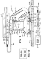
- Security system 1 includes as its main component a display module indicated generally at 3 containing an internal alarm system, and a security sensor indicated generally at 5 for protecting a product or item of merchandise 7 attached to sensor 5.
- Product 7 is illustrated as a cell phone, but can be numerous types of products.
- Display module 3 is intended to be secured to a support 9 by a plurality of fasteners 11 and includes a base 13 and a support column or housing 15 extending upwardly therefrom.
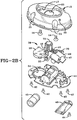
- Housing 15 is mounted within an irregular-shaped recess 17 ( Fig. 2B ) formed in base 13 by fasteners 14.
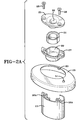
- a cover plate 19 ( Fig. 2A ) is formed with an oval-shaped opening 20 through which housing 15 extends.
- fasteners 11 extend through a plurality of holes 21 formed in base 13 for securing the base on support surface 9.
- Base 13 is formed with a central hole 23 for passage of conductors therethrough for the various functions as discussed below. Referring to Fig.
- a platform 25 is mounted on a cap 27 by a plurality of fasteners 28 with cap 27 being formed with a cylindrical-shaped recess 29 for receiving a ringshaped magnet 31 therein.
- Platform 25 is formed with a central opening 33 in which is inserted a projection 35 formed on sensor 5 ( Fig. 5 ) which contains a second magnet 36 to provide a self-orienting type of sensor and display module arrangement such as shown and described in pending patent application Serial No. 11/454,513 .
- sensor 5 Fig. 5
- second magnet 36 to provide a self-orienting type of sensor and display module arrangement
- Display module 3 is also similar in many respects to that disclosed in pending patent applications Serial No. 11/454,513, filed June 16, 2006 , and Serial No. 11/431,291, filed May 10, 2006 , the contents of which are incorporated herein by reference.
- display module 3 contains an alarm circuitry ( Figs. 2B and 3 ) which is indicated generally at 39, which is mounted on an oval-shaped mounting plate 41 which is mounted within the interior of base 13 by a plurality of fasteners 42.
- the alarm circuitry includes a battery housing 43 in which a battery 45 is secured by a battery closure door 46 and a fastener 44. Battery 45 is in contact with a pair of battery terminals 55.
- Alarm circuitry 39 further includes an LED 47 which is operationally connected to a printed circuit board microprocessor 49. LED 47 is visible through an opening 50 formed in base 13 and an aligned opening 51 formed in cover plate 19.
- An audible alarm such as a piezo electric alarm 53 is connected to circuit board 49 and is located within a circular hole 54 formed in mounting plate 41.
- the alarm circuitry also is connected to a plunger switch 16 mounted within base 13 which includes a plunger 18 which extends through a hole in mounting plate 41 and is depressed to activate the alarm when alarm module 3 is mounted on support 9 as shown in Fig. 1 .
- the particular details of alarm circuitry 39 and printed circuit board 49 are not shown in further detail, but are well-known in the alarm art.
- This arrangement provides a single display module 3 with its own self-contained alarm circuit 39 powered by its own battery 45 for protecting a product 7 secured on sensor 5 as discussed further below.
- a remote source of electric power 57 is connectable to display module 3 by a first power cord 59 which preferably contains a pair of conductors 60 and 61 and may include a pair of connectors 63 and 63A which connect cord sections 59A and 59B which combine to form power cord 59.
- Cord section 59B preferably extends through a hole 65 formed in support 9 and terminates in a plug 67 which has a terminal end connector 69 which extends into and is electrically connected to a power input jack 70 mounted in base 13.
- Power supply 57 preferably will be a usual 120V AC supply readily available throughout a retail store and usually will include a transformer 71 which will convert the 120V AC to a DC voltage, generally in the range of 3V to 9V DC, which voltage is supplied to most types of battery-powered equipment for recharging the internal battery of the type of item to be displayed on display module 3.
- this voltage can change without affecting the concept of the invention.
- the 120V AC power can be supplied directly to display module 3 which contains the appropriate circuitry for converting the AC voltage to a DC voltage for supplying the desired DC voltage to the displayed product as discussed further below with respect to Fig. 9 .
- display module 3 contains the appropriate circuitry for converting the AC voltage to a DC voltage for supplying the desired DC voltage to the displayed product as discussed further below with respect to Fig. 9 .
- a greater DC voltage than the 3V to 9V discussed above could be supplied to display module 3 where this greater DC voltage is stepped down to the voltage required by the particular product secured to sensor 5.
- a power output jack 73 is mounted within housing 15 of display module 3 and receives a plug 75 therein which is mounted on one end of a second power cord 77.
- Power cord 77 preferably has a coiled extensional arrangement enabling it to extend outwardly when a customer is inspecting product 7 and will contain a plurality of electrical conductors.
- the other end of power cord 77 preferably is hardwired into sensor 5 as shown in Fig. 5 , which sensor is removably seated on the upper end of housing 15.
- power cord 77 could be secured to sensor 15 by a plug-in type of attachment without affecting the concept of the invention.
- Sensor 5 ( Fig.
- an LED 83 may be incorporated into sensor 5 and connected to battery 45 of the security system as discussed further below.
- a power jack 85 is mounted within sensor 5 for receiving a terminal 87 of a plug 88 therein.
- Plug 88 is mounted on one end of a third power cord 89 which terminates at a second end in a plug 91.
- Plug 91 has an end terminal configuration 92 which is configured to match the electrical contacts in the receptacle or jack 93.
- a receptacle or jack 93 is provided on most types of powered products, of the type intended for display on module 3, in order to charge the internal battery of the product or provide power to other components of the displayed product.
- a particular power cord 89 will be chosen that has a plug 91 attached thereto that is compatible with the particular receptacle 93 of the particular product to be displayed on module 1.
- the contacts of receptacle 93 will vary depending upon the particular manufacturer of the product in which it is incorporated and the merchant will have several types of power cords 89 that have the particular configured plug 91 on one end thereof in order to be compatible with receptacle 93 of the particular product displayed on module 3.
- Plug 88 preferably is a standard type of a readily available plug having a cylindrical configured terminal 87 formed therein and can be used for connection to power jack 85 incorporated in sensor 5.
- power cord 89 can be hardwired to sensor 5 without affecting its operation and manner of use.
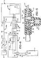
- Fig. 6 is a diagrammatic wiring diagram of one type of electrical circuit which can be used in security system 1 to provide one of the main features of the invention, that is, the supplying of electric power to displayed product 7.
- power cord 77 preferably contains six conductors 94, 95, 96, 97, 98 and 99 which extend between power output jack 75 and sensor 5.
- Conductors 94 and 99 connect power input jack 70 with power output jack 73 and are connected to conductors 60 and 61 of power cord 59. These two conductors 94 and 99 continue through sensor 5 and are connected to power output jack 85 of sensor 5 and supply the electric power to the contacts of receptacle 93 of displayed product 7 through power cord 89.
- conductors 95 and 98 connect to plunger switch 79 with conductors 96 and 97 being connected to LED 83.
- power supply cord 59, and in particular section 59A extending between connector 63 and power supply transformer 71 will be the same as that usually supplied with the particular product 7 to be displayed on module 3 which will ensure that the correct amount of power (DC voltage) is supplied from power supply 57 to product power input jack 93. Therefore, the display module of the present invention, in addition to removably supporting sensor 5 thereon which is attached to the displayed product, provides electrical power from a remote source to the sensor, with the sensor being mechanically and electrically connected to display module 3 by power cord 77 in a simple effective manner.
- the security system of the present invention provides a system which supplies electric power from a remote source through a display module and sensor to a product attached to the sensor to ensure that an internal battery of the displayed product remains energized, as well as supplying power at the correct voltage to other electrical components of the displayed product.
- various conductors and plug configurations are utilized whereby the particular transformer 71 and plug 63, which is compatible with power input jack 93 of the displayed product, is utilized for connection to the remote power source 57 thereby ensuring that the correct voltage is supplied through transformer 71 and ultimately to product 7.
- Connection 63A will be chosen to be complementary to the contacts within plug 63 so as to be electrically and mechanically connected thereto as shown in Fig.
- Plug 67 can be a standard type of plug having a cylindrical terminal 69 used for various plug configurations in combination with plug 63A for use with power input jack 70.
- plug 88 can have the same cylindrical type terminal 87 for the various power cords 89 which will require a different plug 91 on the opposite end thereof for compatibility with product input jack 93.
- Output jack plug 75 can be a removable clip-type plug as shown in Figs. 1 and 4 , or if desired, be eliminated by hardwiring the conductors of power cord 77 to the corresponding conductors within housing 15.
- power cord 77 can be hardwired into sensor 5 or removably attached by a jack (not shown) without affecting the concept of the invention.
- the self-contained alarm system 39 which includes audible alarm 53 and battery 45 is mounted within display module 3 and is dedicated to protecting the single product 7 secured to sensor 5. This protection is provided whether display module 3 is or is not connected to the remote source of electricity. This enables the display module and sensor to be placed at various locations and the product attached to sensor 5 to be periodically replaced without disturbing adjacent displayed products and alarm systems.
- alarm circuitry 39 will sound alarm 53 upon actuation of plunger switch 79 upon the removal of product 7 from sensor 5 or upon actuation of plunger switch 16 upon removal of alarm module 3 from support 9.
- the alarm circuitry provides a sense loop through power cords 77 and 89 which will sound an alarm if plug 91 is removed from product 7 or from sensor 5, or if plug 75 is removed from power output jack 73, or if either power cord 77 or 89 is severed.
- the alarm circuitry can be configured that upon removal of plug 67 from input jack 70 alarm 53 will sound, all of which provides additional security to the security system of the present invention.
- LEDs 47 and 83 will be fully illuminated or blinking upon the alarm system being activated, which will notify the store personnel and a potential thief that the merchandise is protected by an active alarm system.
- Fig. 9 shows a modified schematic wiring diagram which can be utilized in the security system of the present invention. Electric power is supplied to the printed circuit board 49 and the alarm circuitry and in particular audible alarm 53, either from the remote 120V AC power supply or from internal battery 45.
- This modified schematic is indicated generally at 100, and includes two main portions 101 and 102.
- Circuit portion 101 contains the power supply circuitry and includes as its main components inputs 103 which connect to the remote source of 120V AC power and to a transformer (not shown) which converts this AC power to a DC voltage, for example, 5-18V DC.
- a linear regulator 105 converts this DC input voltage to a DC output voltage, for example 4.6V DC.
- Another linear regulator 107 converts this 4.6V DC to a desired DC voltage for microprocessor 49, for example 3.3V DC.
- Four diodes 108, 109, 110 and 111 provide a switching function as discussed below.
- a transistor 113 provides a signal to printed circuit board 49 through conductor 115 indicating to board 49 that it is being powered either by the external power source or internal battery 45.
- Alarm circuitry 102 is a standard alarm circuitry of the type used to protect displayed products wherein a sense loop is provided in one or more conductor cables attached to the protected product and/or attached sensor or to one or more plunger or pressure switches which connect the product to a sensor or a display module to a support structure. Likewise, alarm circuitry supplies power to various visual indicators 47 and 83 (LED) as discussed above or can be used to program security codes etc. into the system, some of which are not utilized in the present invention.
- LED visual indicators 47 and 83
- the 120V AC supply is used to supply the desired DC voltage to printed circuit board microprocessor 49 through linear regulators 105 and 107 and other circuit components.
- switching diodes 108-111 will immediately switch the power supply for the alarm circuitry to battery 45 which then supplies the power to circuit board 49, the various sense loops, audible alarm 53 and the various safety pressure switches.
- the appropriate signal is then supplied through transistor 113 and conductor 115 to circuit board 49 as discussed above. This ensures that the displayed product is protected from theft and still can be supplied with the desired DC voltage for its operation by its own internal battery even when the main AC power source is interrupted. It also avoids using battery 45 until required to protect the displayed product by using the remote source of AC power.
- the 4.6V DC output of linear regulator 105 preferably is used to supply the necessary voltage to LED 83 and to the piezo speaker 53 and which will always be greater than the supply voltage, for example the 3.3V for microprocessor 49. Also, the DC power supply from remote AC source, preferably will always be higher than the DC voltage of 4.6 provided by the output of linear regulator 105.
Landscapes
- Physics & Mathematics (AREA)
- General Physics & Mathematics (AREA)
- Electromagnetism (AREA)
- Burglar Alarm Systems (AREA)
- Alarm Systems (AREA)
- Devices For Indicating Variable Information By Combining Individual Elements (AREA)
Claims (9)
- Ein Sicherheitssystem (1) zum Ausstellen und Schützen eines einzelnen ausgestellten Produkts (7), umfassend:ein einzelnes Ausstellungsmodul (3), das auf einem Träger (9) montiert werden kann;einen Sensor (5), welcher abnehmbar auf dem einzelnen Ausstellungsmodul (3) sitzt und mit dem einzelnen ausgestellten Produkt (7) verbunden ist;eine abgelegene Quelle für elektrische Energie (57);ein erstes Netzkabel (59), welches das einzelne Ausstellungsmodul (3) elektrisch mit der Quelle für elektrische Energie (57) verbindet;ein zweites Netzkabel (77), welches das einzelne Ausstellungsmodul (3) elektrisch undmechanisch mit dem Sensor (5) verbindet;ein drittes Netzkabel (89), welches den Sensor (5) elektrisch und mechanisch mit dem einzelnen ausgestellten Produkt (7) verbindet,wobei das erste, das zweite und das dritte Netzkabel (59, 77, 89) einen elektrischen Pfad bereitstellen, welcher sich von der abgelegenen Quelle für elektrischen Strom (57) durch das einzelne Ausstellungsmodul (3) zu dem einzelnen ausgestellten Produkt (7) erstreckt, undwobei eine Alarmschaltung (39) in dem einzelnen Ausstellungsmodul (3) enthalten ist sowie eine Abtastschleife durch das zweite Netzkabel (77) und einen akustischen Alarm (53) zum Ausgeben eines Alarms, wenn die Integrität des zweiten Netzkabels (77) beeinträchtigt ist, bereitstellt;dadurch gekennzeichnet, dassdie Alarmschaltung (39) ferner eine Abtastschleife durch das dritte Netzkabel (89) bereitstellt und der akustische Alarm (53) einen Alarm ausgibt, wenn die Integrität des dritten Netzkabels (89) beeinträchtigt ist;der Sensor (5) einen internen Stößelschalter (79) oder Druckschalter enthält, der so konfiguriert ist, dass er das Alarmsystem aktiviert, wenn der Sensor (5) an dem einzelnen ausgestellten Produkt (7) befestigt wird; undein weiterer Stößelschalter (16) oder Druckschalter innerhalb des einzelnen Ausstellungsmoduls (3) montiert und so konfiguriert ist, dass er das Alarmsystem aktiviert, wenn das einzelne Ausstellungsmodul (3) auf dem Träger (9) montiert wird,wobei die Alarmschaltung (39) so konfiguriert ist, dass sie einen Alarm ausgibt, wenn das einzelne ausgestellte Produkt (7) vom Sensor (5) entfernt wird oder wenn das einzelne Ausstellungsmodul (3) vom Träger (9) entfernt wird, nämlich bei Auslösung des internen Stößelschalters (79) oder Druckschalters oder bei Auslösung des weiteren Stößelschalters (16) oder Druckschalters.
- Das Sicherheitssystem nach Anspruch 1, wobei eine Stromeingangsbuchse (70) in dem einzelnen Ausstellungsmodul (3) angebracht und mit einem ersten Ende des ersten Netzkabels (59) verbunden ist; und wobei eine Stromausgangsbuchse (73) in dem einzelnen Ausstellungsmodul (3) enthalten und mit einem ersten Ende des zweiten Netzkabels (77) verbunden ist.
- Das Sicherheitssystem nach Anspruch 2, wobei die Stromeingangsbuchse (70) und die Stromausgangsbuchse (73) innerhalb des einzelnen Ausstellungsmoduls (3) elektrisch verbunden sind.
- Das Sicherheitssystem nach Anspruch 1, wobei das dritte Netzkabel (89) ein erstes und ein zweites Ende aufweist; und wobei das erste Ende durch einen ersten lösbaren Verbinder (88) mit dem Sensor (5) verbunden ist und das zweite Ende durch einen zweiten lösbaren Verbinder (91) mit dem einzelnen ausgestellten Produkt (7) verbunden ist.
- Das Sicherheitssystem nach Anspruch 1, wobei das zweite Netzkabel (77) ein erstes und ein zweites Ende aufweist, wobei das erste Ende fest mit dem Sensor (5) verkabelt ist; und wobei das zweite Ende lösbar mit dem einzelnen Ausstellungsmodul (3) verbunden ist.
- Das Sicherheitssystem nach Anspruch 1, wobei die Alarmschaltung (39) eine optische Anzeige (47, 83) enthält, die anzeigt, dass die Alarmschaltung aktiviert ist.
- Das Sicherheitssystem nach Anspruch 1, wobei das zweite Netzkabel (77) eine ausziehbare aufgewickelte Kordel ist.
- Das Sicherheitssystem nach Anspruch 1, wobei das zweite Netzkabel (77) sechs Leiter (94, 95, 96, 97, 98, 99) enthält; wobei der erste und der zweite Leiter (94, 99) der sechs Leiter elektrisch mit der abgelegenen Quelle für elektrische Energie (57) und mit dem einzelnen ausgestellten Produkt (7) verbunden sind, um das Produkt mit elektrischer Energie zu versorgen.
- Das Sicherheitssystem nach Anspruch 8, wobei der dritte und der vierte Leiter (95, 98) der sechs Leiter elektrisch mit dem internen Stößelschalter (79) verbunden sind; und wobei der fünfte und der sechste Leiter (96, 97) der sechs Leiter elektrisch mit einer in dem Sensor angebrachten optischen Anzeige (83) verbunden sind.
Applications Claiming Priority (4)
| Application Number | Priority Date | Filing Date | Title |
|---|---|---|---|
| US88011507P | 2007-01-12 | 2007-01-12 | |
| US88013207P | 2007-01-12 | 2007-01-12 | |
| US11/970,146 US7710266B2 (en) | 2007-01-12 | 2008-01-07 | Security system with product power capability |
| PCT/US2008/000265 WO2008088699A2 (en) | 2007-01-12 | 2008-01-08 | Security system with product power capability |
Publications (3)
| Publication Number | Publication Date |
|---|---|
| EP2102833A2 EP2102833A2 (de) | 2009-09-23 |
| EP2102833A4 EP2102833A4 (de) | 2012-06-06 |
| EP2102833B1 true EP2102833B1 (de) | 2020-12-16 |
Family
ID=39617327
Family Applications (1)
| Application Number | Title | Priority Date | Filing Date |
|---|---|---|---|
| EP08705531.5A Not-in-force EP2102833B1 (de) | 2007-01-12 | 2008-01-08 | Sicherheitssystem mit produktleistungsfunktion |
Country Status (5)
| Country | Link |
|---|---|
| US (1) | US7710266B2 (de) |
| EP (1) | EP2102833B1 (de) |
| CN (1) | CN101632106B (de) |
| AU (1) | AU2008205649B2 (de) |
| WO (1) | WO2008088699A2 (de) |
Families Citing this family (81)
| Publication number | Priority date | Publication date | Assignee | Title |
|---|---|---|---|---|
| US20110276609A1 (en) | 2001-12-27 | 2011-11-10 | Denison William D | Method for Controlling and Recording the Security of an Enclosure |
| US8102262B2 (en) * | 2006-03-31 | 2012-01-24 | Checkpoint Systems, Inc. | Charging merchandise items |
| US7626500B2 (en) * | 2007-01-12 | 2009-12-01 | Invue Security Products Inc. | Security display with central control system |
| US8092251B2 (en) * | 2007-12-29 | 2012-01-10 | Apple Inc. | Active electronic media device packaging |
| US8698617B2 (en) * | 2010-06-21 | 2014-04-15 | Mobile Tech, Inc. | Display for hand-held electronics |
| US10373456B2 (en) | 2009-01-10 | 2019-08-06 | Mobile Tech, Inc. | Display for hand-held electronics |
| US11344140B2 (en) * | 2009-01-10 | 2022-05-31 | Mobile Tech, Inc. | Display for hand-held electronics |
| US20140159898A1 (en) | 2010-06-21 | 2014-06-12 | Mobile Technologies, Inc. | Display for hand-held electronics |
| US8542119B2 (en) * | 2009-01-13 | 2013-09-24 | Invue Security Products Inc. | Combination non-programmable and programmable key for security device |
| US20100176945A1 (en) * | 2009-01-14 | 2010-07-15 | Invue Security Products Inc. | Detachable carriage for merchandise security system |
| US20110047844A1 (en) * | 2009-09-01 | 2011-03-03 | Invue Security Products Inc. | Merchandise display stand and removable label holder |
| US8360373B2 (en) | 2009-09-17 | 2013-01-29 | Target Brands, Inc. | Display apparatus and method |
| US8537013B2 (en) * | 2009-09-23 | 2013-09-17 | Checkpoint Systems, Inc. | Display assembly with interchangeable head devices |
| US8242906B2 (en) * | 2009-10-09 | 2012-08-14 | Invue Security Products Inc. | Merchandise display stand defining an angled exit path |
| US7744404B1 (en) | 2009-11-03 | 2010-06-29 | Merchandising Technologies, Inc. | Cable management system for product display |
| US20110187531A1 (en) * | 2009-12-14 | 2011-08-04 | Apple Inc. | Systems and methods for securing handheld electronic devices |
| US8564438B2 (en) * | 2010-03-16 | 2013-10-22 | Invue Security Products Inc. | Merchandise display security system including magnetic sensor |
| HU3840U (en) * | 2010-05-04 | 2010-10-28 | Ambrus Sandor Dr | Theft-preventing holder unit for anti-theft apparatuses of portable electric products |
| US8698618B2 (en) * | 2010-06-21 | 2014-04-15 | Mobile Tech, Inc. | Display for hand-held electronics |
| US8368536B2 (en) * | 2010-07-20 | 2013-02-05 | Invue Security Products Inc. | Merchandise display security devices including anti-theft features |
| US8558414B2 (en) | 2010-08-11 | 2013-10-15 | Invue Security Products Inc. | Voltage regulator for merchandise display security device |
| US9097380B2 (en) * | 2010-08-11 | 2015-08-04 | Mobile Tech, Inc. | Adjustable security bracket |
| WO2013105980A2 (en) * | 2011-01-17 | 2013-07-18 | Invue Security Products Inc. | Merchandise display security device for headphones |
| US8674833B2 (en) | 2011-01-31 | 2014-03-18 | Invue Security Products Inc. | Universal camera sensor having movable mount for retaining power connector |
| US9092960B2 (en) * | 2011-05-05 | 2015-07-28 | Mobile Tech, Inc. | Retail security system |
| US8994531B2 (en) | 2011-08-03 | 2015-03-31 | Invue Security Products Inc. | Merchandise sensor and method for protecting an item of merchandise |
| US8941388B2 (en) | 2011-08-13 | 2015-01-27 | Tracthat Llc | Auto-calibrating proximity sensor for retail display security system |
| US20130149893A1 (en) * | 2011-12-13 | 2013-06-13 | Invue Security Products Inc. | Power adapter cord including rotatable connector |
| US10706694B2 (en) * | 2011-12-21 | 2020-07-07 | Mobile Tech, Inc. | Security/tether cable |
| US8736450B2 (en) * | 2012-04-04 | 2014-05-27 | International Business Machines Corporation | Theft deterrent device |
| US9000920B2 (en) * | 2012-05-15 | 2015-04-07 | Invue Security Products Inc. | Reduced cost merchandise display security device including merchandise power supply |
| US8517748B1 (en) | 2012-07-23 | 2013-08-27 | Vanguard Products Group, Inc. | Communication connector with analog coupling circuit |
| WO2014019072A1 (en) * | 2012-08-01 | 2014-02-06 | Kobold Will | Security system |
| US9303809B2 (en) | 2012-08-30 | 2016-04-05 | Sennco Solutions, Inc. | Apparatus, system and method for securing, attaching and/or detaching a device to a fixture |
| US8814128B2 (en) | 2012-09-28 | 2014-08-26 | Target Brands, Inc. | Display system for mobile electronic devices and associated methods |
| USD686629S1 (en) | 2012-09-28 | 2013-07-23 | Target Brands, Inc. | Device display fixture |
| US9474392B2 (en) | 2012-10-15 | 2016-10-25 | Apple Inc. | Methods and systems for displaying a product |
| US9667093B2 (en) * | 2012-11-24 | 2017-05-30 | Karl F. Scheucher | Transportable power plant apparatus and method |
| US9760116B2 (en) | 2012-12-05 | 2017-09-12 | Mobile Tech, Inc. | Docking station for tablet device |
| US10424882B2 (en) | 2013-05-09 | 2019-09-24 | Invue Security Products Inc. | Security connector |
| CN205451350U (zh) | 2013-05-17 | 2016-08-10 | Invue安全产品公司 | 一种用于保护商品避免被盗的报警线缆系统 |
| AU2014330044A1 (en) | 2013-06-11 | 2015-12-03 | Invue Security Products Inc. | Anti-theft device for portable electronic device |
| US10111537B2 (en) | 2013-10-08 | 2018-10-30 | Invue Security Products Inc. | Quick release sensor for merchandise display |
| CN105849786B (zh) * | 2013-10-30 | 2018-11-13 | Invue安全产品公司 | 用于便携电子装置的挠性传感器 |
| WO2015112670A1 (en) | 2014-01-23 | 2015-07-30 | Invue Security Products Inc. | Systems and methods for security sensing in a power cable for an article of merchandise |
| US10206522B2 (en) * | 2014-01-24 | 2019-02-19 | Apple Inc. | Display systems and methods |
| US9443404B2 (en) | 2014-02-14 | 2016-09-13 | Invue Security Products Inc. | Tethered security system with wireless communication |
| US10312731B2 (en) | 2014-04-24 | 2019-06-04 | Westrock Shared Services, Llc | Powered shelf system for inductively powering electrical components of consumer product packages |
| TWI556535B (zh) * | 2014-04-29 | 2016-11-01 | 移動技術公司 | 用於手持電子裝置之陳列架 |
| WO2015200504A1 (en) * | 2014-06-24 | 2015-12-30 | BEFFREY, Kelly | Collapsible light box |
| US10197888B2 (en) | 2014-06-24 | 2019-02-05 | Aaron Johnson | Collapsible light box |
| WO2016011108A1 (en) * | 2014-07-16 | 2016-01-21 | Invue Security Products Inc. | Security system with kill switch functionality |
| WO2016014614A1 (en) * | 2014-07-24 | 2016-01-28 | Invue Security Products Inc. | Sensor powered by item of merchandise for retail security |
| US9222285B1 (en) | 2014-08-01 | 2015-12-29 | Perseus Micro Logic Corporation | Theft deterrent device and method of use |
| US10098481B2 (en) | 2014-08-27 | 2018-10-16 | Invue Security Products Inc. | Systems and methods for locking a sensor to a base |
| WO2016122878A1 (en) * | 2015-01-27 | 2016-08-04 | Invue Security Products Inc. | Merchandise display security device with headphone jack sensor |
| US9460594B1 (en) * | 2015-03-09 | 2016-10-04 | Sennco Solutions Inc. | Apparatus, system and method for positioning a cable with a sensor by a rotatable cable assembly |
| KR102004459B1 (ko) | 2015-05-05 | 2019-07-26 | 인뷰 시큐어리티 프로덕트 주식회사 | 낮은 프로파일 상품 보안 시스템 |
| WO2016187268A1 (en) * | 2015-05-21 | 2016-11-24 | Invue Security Products Inc. | Security system for dynamically loaded merchandise |
| KR20180027544A (ko) * | 2015-08-14 | 2018-03-14 | 인뷰 시큐어리티 프로덕트 주식회사 | 헤드폰을 위한 상품 진열 보안 디바이스 |
| ES2731689T3 (es) * | 2015-10-12 | 2019-11-18 | Invue Security Products Inc | Fuente de alimentación para un sistema de seguridad de mercancías |
| US10886765B2 (en) * | 2015-11-09 | 2021-01-05 | Johnson Industries, Inc. | Lighted connector for a battery cable |
| US10728868B2 (en) | 2015-12-03 | 2020-07-28 | Mobile Tech, Inc. | Remote monitoring and control over wireless nodes in a wirelessly connected environment |
| US10517056B2 (en) | 2015-12-03 | 2019-12-24 | Mobile Tech, Inc. | Electronically connected environment |
| US11109335B2 (en) | 2015-12-03 | 2021-08-31 | Mobile Tech, Inc. | Wirelessly connected hybrid environment of different types of wireless nodes |
| US10251144B2 (en) | 2015-12-03 | 2019-04-02 | Mobile Tech, Inc. | Location tracking of products and product display assemblies in a wirelessly connected environment |
| ES2919776T3 (es) | 2016-04-15 | 2022-07-28 | Mobile Tech Inc | Control de autorización para un sistema de seguridad antirrobo |
| CN205882739U (zh) * | 2016-05-18 | 2017-01-11 | 严兵 | 一种无线式万能充电手机支架 |
| WO2017214123A1 (en) * | 2016-06-07 | 2017-12-14 | Invue Security Products Inc. | Merchandise security device with breakaway feature |
| US10101770B2 (en) | 2016-07-29 | 2018-10-16 | Mobile Tech, Inc. | Docking system for portable computing device in an enclosure |
| US10427618B2 (en) * | 2017-02-20 | 2019-10-01 | Panasonic Automotive Systems Company Of America, Division Of Panasonic Corporation Of North America | Universal mechanical dock |
| US10630873B2 (en) * | 2017-07-27 | 2020-04-21 | Command Sight, Inc. | Animal-wearable first person view system |
| USD876264S1 (en) * | 2018-02-09 | 2020-02-25 | Invue Security Products Inc. | Sensor for a merchandise security device |
| US12035422B2 (en) | 2018-10-25 | 2024-07-09 | Mobile Tech, Inc. | Proxy nodes for expanding the functionality of nodes in a wirelessly connected environment |
| US10614682B1 (en) | 2019-01-24 | 2020-04-07 | Mobile Tech, Inc. | Motion sensing cable for tracking customer interaction with devices |
| WO2020172166A1 (en) * | 2019-02-19 | 2020-08-27 | Mobile Tech, Inc. | Product merchandising display system |
| US11221101B2 (en) | 2019-06-21 | 2022-01-11 | Apple Inc. | Product-display system |
| US20210196058A1 (en) * | 2019-12-30 | 2021-07-01 | Mobile Tech, Inc. | Product merchandising systems with modular puck assemblies for mounting and displaying products |
| US11942269B1 (en) * | 2022-02-11 | 2024-03-26 | Marc Tobias | Security assembly for a security system |
| CN114783232B (zh) * | 2022-04-25 | 2023-10-20 | 国网河北省电力有限公司平山县供电分公司 | 一种用电安全普及营销装置 |
| US12428878B1 (en) | 2024-05-31 | 2025-09-30 | Invue Security Products Inc. | Security device |
Citations (1)
| Publication number | Priority date | Publication date | Assignee | Title |
|---|---|---|---|---|
| WO2006078476A2 (en) * | 2005-01-14 | 2006-07-27 | Alpha Security Products, Inc. | Portable alarming security device |
Family Cites Families (33)
| Publication number | Priority date | Publication date | Assignee | Title |
|---|---|---|---|---|
| US3710224A (en) | 1970-12-31 | 1973-01-09 | Sperry Rand Corp | Display stand for rechargeable battery operated appliance |
| US4618857A (en) | 1984-06-20 | 1986-10-21 | Harvey W. Dubois | Low D.C. and loss of A.C. sensor and alarm with service inhibitor |
| US4620182A (en) | 1985-01-10 | 1986-10-28 | Check Mate Systems, Inc. | Security apparatus for retail goods |
| US4598827A (en) | 1985-01-14 | 1986-07-08 | Keifer Terry A | Versatile garment security device |
| US5341124A (en) | 1991-05-29 | 1994-08-23 | Se-Kure Controls, Inc. | Mountable product sensor and display stand |
| US5517175A (en) | 1993-06-24 | 1996-05-14 | Stellar Security Products, Inc. | Potential adjusting sensor supervision circuit |
| US5604484A (en) | 1995-07-31 | 1997-02-18 | Rogers; Robert | Electronic pin fastener |
| US5838225A (en) | 1995-08-10 | 1998-11-17 | Micro Switch Corporation | Anti-theft alarm for electrically operated devices |
| US5617073A (en) | 1996-01-05 | 1997-04-01 | Minatronics Corporation | Method and apparatus for linking an object with a slot to a cable |
| US5861807A (en) * | 1997-11-12 | 1999-01-19 | Se-Kure Controls, Inc. | Security system |
| US6386906B1 (en) | 1998-03-16 | 2002-05-14 | Telefonix Inc | Cord management apparatus and method |
| US5886633A (en) | 1998-06-29 | 1999-03-23 | I.S.P.A. Woodworking Limited | Selectively disconnectable sensor switch for an alarm |
| US6104289A (en) | 1999-06-10 | 2000-08-15 | Protex International Corp. | Supervised anti-theft security system for product displays |
| US6150940A (en) | 1999-08-10 | 2000-11-21 | Chapman; Glenn H. | Anti-theft electrical power cord |
| EP1093744A3 (de) | 1999-10-22 | 2003-07-09 | Reinhold Ott | Vorrichtung zur Sicherung einer Ware gegen Diebstahl |
| US6690277B1 (en) | 2000-03-24 | 2004-02-10 | Henry Louis Hansen | Security system |
| CA2305080A1 (en) | 2000-04-12 | 2001-10-12 | Cda Industries Inc. | Tamper-proof display |
| JP3706820B2 (ja) | 2001-06-22 | 2005-10-19 | 松尾産業株式会社 | 商品盗難監視装置及び付設ユニット |
| ITVR20010052A1 (it) * | 2001-05-03 | 2002-11-03 | Ferruccio Bonato | Dispositivo antitaccheggio particolarmente per espositori sistemabiliin punti vendita |
| US6509659B1 (en) | 2001-10-24 | 2003-01-21 | Motorola, Inc. | Cable or module identification apparatus and method |
| US6756900B2 (en) | 2002-01-04 | 2004-06-29 | Se-Kure Controls, Inc. | Voltage selectable alarm sensor |
| US6836214B2 (en) | 2002-03-04 | 2004-12-28 | Sang J. Choi | Burglar alarm |
| US6956479B2 (en) | 2003-02-05 | 2005-10-18 | Vanguard Products Group, Inc. | Sensors and methods for detecting attachment to a surface |
| US7015596B2 (en) | 2003-07-03 | 2006-03-21 | Opher Pail | Electronic device display system and method |
| US7011009B1 (en) | 2003-11-21 | 2006-03-14 | Jennifer Lynne Tomich | Magnetically aligned hole punch |
| US7202786B2 (en) * | 2004-05-25 | 2007-04-10 | Sennco Solutions, Inc. | Apparatus, a system and a method for securing and/or for monitoring a device |
| DE102004053426A1 (de) | 2004-11-05 | 2006-05-11 | Ott, Reinhold, Waterloo | Sensorvorrichtung, Überwachungssystem und Verfahren zum Betreiben eines Überwachungssystems zur Überwachung einer Ware |
| US20060145848A1 (en) | 2004-12-28 | 2006-07-06 | Alpha Security Products, Inc. | Electronic security device and system for articles of merchandise |
| US7593142B2 (en) * | 2005-02-09 | 2009-09-22 | Sennco Solutions, Inc. | Apparatus, a system and a method for detecting a security of a device with an optical sensor |
| US7209038B1 (en) * | 2005-03-17 | 2007-04-24 | Protex International Corporation | Security system for power and display of consumer electronic devices |
| US7187284B2 (en) | 2005-03-28 | 2007-03-06 | Martin Masciantonio | Active anti-theft device for securing property |
| HU3131U (en) * | 2005-12-07 | 2006-07-28 | Sandor Dr Ambrus | Anti-theft device for goods |
| US7626500B2 (en) * | 2007-01-12 | 2009-12-01 | Invue Security Products Inc. | Security display with central control system |
-
2008
- 2008-01-07 US US11/970,146 patent/US7710266B2/en active Active
- 2008-01-08 EP EP08705531.5A patent/EP2102833B1/de not_active Not-in-force
- 2008-01-08 AU AU2008205649A patent/AU2008205649B2/en not_active Ceased
- 2008-01-08 CN CN2008800020281A patent/CN101632106B/zh not_active Expired - Fee Related
- 2008-01-08 WO PCT/US2008/000265 patent/WO2008088699A2/en not_active Ceased
Patent Citations (1)
| Publication number | Priority date | Publication date | Assignee | Title |
|---|---|---|---|---|
| WO2006078476A2 (en) * | 2005-01-14 | 2006-07-27 | Alpha Security Products, Inc. | Portable alarming security device |
Also Published As
| Publication number | Publication date |
|---|---|
| WO2008088699A2 (en) | 2008-07-24 |
| US20080169923A1 (en) | 2008-07-17 |
| AU2008205649A1 (en) | 2008-07-24 |
| CN101632106B (zh) | 2012-11-14 |
| HK1140047A1 (en) | 2010-09-30 |
| AU2008205649B2 (en) | 2010-11-18 |
| EP2102833A2 (de) | 2009-09-23 |
| CN101632106A (zh) | 2010-01-20 |
| WO2008088699A3 (en) | 2009-09-03 |
| US7710266B2 (en) | 2010-05-04 |
| EP2102833A4 (de) | 2012-06-06 |
Similar Documents
| Publication | Publication Date | Title |
|---|---|---|
| EP2102833B1 (de) | Sicherheitssystem mit produktleistungsfunktion | |
| US7626500B2 (en) | Security display with central control system | |
| US8395907B2 (en) | Multi-sensor alarm apparatus, system and/or method for securing articles | |
| US11816966B2 (en) | Low profile merchandise security system | |
| US10217338B2 (en) | Display for hand-held electronics | |
| US7209038B1 (en) | Security system for power and display of consumer electronic devices | |
| US8872659B2 (en) | Merchandise display security device for headphones | |
| US10349758B2 (en) | Mount or stand for presentation of wearable electronic products | |
| CN204375120U (zh) | 用于商品的商品陈列安全装置 | |
| CN103210432A (zh) | 包括用于保持电源适配器线的装置的商品展示安全设备 | |
| US9171439B2 (en) | Method and apparatus for powering a security device | |
| CN113706805A (zh) | 商品安全系统 | |
| US20070171061A1 (en) | Theft deterrent device with dual sensor assembly | |
| HK1140047B (en) | Security system with product power capability | |
| KR101428493B1 (ko) | 시연중인 스마트폰의 도난을 알려주는 경보시스템 | |
| CN213399878U (zh) | 一种用于商品防盗的安全装置 | |
| WO2019079542A1 (en) | PORTABLE ELECTRONIC DEVICE SENSOR | |
| HK1186828A (en) | Merchandise display security device including means for retaining power adapter cord |
Legal Events
| Date | Code | Title | Description |
|---|---|---|---|
| PUAI | Public reference made under article 153(3) epc to a published international application that has entered the european phase |
Free format text: ORIGINAL CODE: 0009012 |
|
| 17P | Request for examination filed |
Effective date: 20090729 |
|
| AK | Designated contracting states |
Kind code of ref document: A2 Designated state(s): AT BE BG CH CY CZ DE DK EE ES FI FR GB GR HR HU IE IS IT LI LT LU LV MC MT NL NO PL PT RO SE SI SK TR |
|
| R17D | Deferred search report published (corrected) |
Effective date: 20090903 |
|
| DAX | Request for extension of the european patent (deleted) | ||
| A4 | Supplementary search report drawn up and despatched |
Effective date: 20120507 |
|
| RIC1 | Information provided on ipc code assigned before grant |
Ipc: G08B 13/14 20060101AFI20120427BHEP Ipc: E05B 73/00 20060101ALI20120427BHEP Ipc: A47F 7/024 20060101ALI20120427BHEP Ipc: G09F 3/14 20060101ALI20120427BHEP Ipc: H02G 11/00 20060101ALI20120427BHEP Ipc: E05B 45/00 20060101ALI20120427BHEP |
|
| 17Q | First examination report despatched |
Effective date: 20130225 |
|
| APBK | Appeal reference recorded |
Free format text: ORIGINAL CODE: EPIDOSNREFNE |
|
| APBN | Date of receipt of notice of appeal recorded |
Free format text: ORIGINAL CODE: EPIDOSNNOA2E |
|
| APBR | Date of receipt of statement of grounds of appeal recorded |
Free format text: ORIGINAL CODE: EPIDOSNNOA3E |
|
| APAK | Date of receipt of statement of grounds of an appeal modified |
Free format text: ORIGINAL CODE: EPIDOSCNOA3E |
|
| APAV | Appeal reference deleted |
Free format text: ORIGINAL CODE: EPIDOSDREFNE |
|
| RAP1 | Party data changed (applicant data changed or rights of an application transferred) |
Owner name: INVUE SECURITY PRODUCTS, INC. |
|
| APBT | Appeal procedure closed |
Free format text: ORIGINAL CODE: EPIDOSNNOA9E |
|
| GRAP | Despatch of communication of intention to grant a patent |
Free format text: ORIGINAL CODE: EPIDOSNIGR1 |
|
| STAA | Information on the status of an ep patent application or granted ep patent |
Free format text: STATUS: GRANT OF PATENT IS INTENDED |
|
| INTG | Intention to grant announced |
Effective date: 20200717 |
|
| GRAS | Grant fee paid |
Free format text: ORIGINAL CODE: EPIDOSNIGR3 |
|
| GRAA | (expected) grant |
Free format text: ORIGINAL CODE: 0009210 |
|
| STAA | Information on the status of an ep patent application or granted ep patent |
Free format text: STATUS: THE PATENT HAS BEEN GRANTED |
|
| AK | Designated contracting states |
Kind code of ref document: B1 Designated state(s): AT BE BG CH CY CZ DE DK EE ES FI FR GB GR HR HU IE IS IT LI LT LU LV MC MT NL NO PL PT RO SE SI SK TR |
|
| REG | Reference to a national code |
Ref country code: GB Ref legal event code: FG4D |
|
| REG | Reference to a national code |
Ref country code: IE Ref legal event code: FG4D |
|
| REG | Reference to a national code |
Ref country code: DE Ref legal event code: R096 Ref document number: 602008063572 Country of ref document: DE |
|
| REG | Reference to a national code |
Ref country code: AT Ref legal event code: REF Ref document number: 1346282 Country of ref document: AT Kind code of ref document: T Effective date: 20210115 |
|
| PG25 | Lapsed in a contracting state [announced via postgrant information from national office to epo] |
Ref country code: GR Free format text: LAPSE BECAUSE OF FAILURE TO SUBMIT A TRANSLATION OF THE DESCRIPTION OR TO PAY THE FEE WITHIN THE PRESCRIBED TIME-LIMIT Effective date: 20210317 Ref country code: FI Free format text: LAPSE BECAUSE OF FAILURE TO SUBMIT A TRANSLATION OF THE DESCRIPTION OR TO PAY THE FEE WITHIN THE PRESCRIBED TIME-LIMIT Effective date: 20201216 Ref country code: NO Free format text: LAPSE BECAUSE OF FAILURE TO SUBMIT A TRANSLATION OF THE DESCRIPTION OR TO PAY THE FEE WITHIN THE PRESCRIBED TIME-LIMIT Effective date: 20210316 |
|
| PGFP | Annual fee paid to national office [announced via postgrant information from national office to epo] |
Ref country code: FR Payment date: 20210202 Year of fee payment: 14 |
|
| REG | Reference to a national code |
Ref country code: AT Ref legal event code: MK05 Ref document number: 1346282 Country of ref document: AT Kind code of ref document: T Effective date: 20201216 |
|
| REG | Reference to a national code |
Ref country code: NL Ref legal event code: MP Effective date: 20201216 |
|
| PG25 | Lapsed in a contracting state [announced via postgrant information from national office to epo] |
Ref country code: LV Free format text: LAPSE BECAUSE OF FAILURE TO SUBMIT A TRANSLATION OF THE DESCRIPTION OR TO PAY THE FEE WITHIN THE PRESCRIBED TIME-LIMIT Effective date: 20201216 Ref country code: SE Free format text: LAPSE BECAUSE OF FAILURE TO SUBMIT A TRANSLATION OF THE DESCRIPTION OR TO PAY THE FEE WITHIN THE PRESCRIBED TIME-LIMIT Effective date: 20201216 Ref country code: BG Free format text: LAPSE BECAUSE OF FAILURE TO SUBMIT A TRANSLATION OF THE DESCRIPTION OR TO PAY THE FEE WITHIN THE PRESCRIBED TIME-LIMIT Effective date: 20210316 |
|
| PGFP | Annual fee paid to national office [announced via postgrant information from national office to epo] |
Ref country code: DE Payment date: 20210127 Year of fee payment: 14 |
|
| PG25 | Lapsed in a contracting state [announced via postgrant information from national office to epo] |
Ref country code: HR Free format text: LAPSE BECAUSE OF FAILURE TO SUBMIT A TRANSLATION OF THE DESCRIPTION OR TO PAY THE FEE WITHIN THE PRESCRIBED TIME-LIMIT Effective date: 20201216 Ref country code: NL Free format text: LAPSE BECAUSE OF FAILURE TO SUBMIT A TRANSLATION OF THE DESCRIPTION OR TO PAY THE FEE WITHIN THE PRESCRIBED TIME-LIMIT Effective date: 20201216 |
|
| REG | Reference to a national code |
Ref country code: LT Ref legal event code: MG9D |
|
| PG25 | Lapsed in a contracting state [announced via postgrant information from national office to epo] |
Ref country code: LT Free format text: LAPSE BECAUSE OF FAILURE TO SUBMIT A TRANSLATION OF THE DESCRIPTION OR TO PAY THE FEE WITHIN THE PRESCRIBED TIME-LIMIT Effective date: 20201216 Ref country code: EE Free format text: LAPSE BECAUSE OF FAILURE TO SUBMIT A TRANSLATION OF THE DESCRIPTION OR TO PAY THE FEE WITHIN THE PRESCRIBED TIME-LIMIT Effective date: 20201216 Ref country code: CZ Free format text: LAPSE BECAUSE OF FAILURE TO SUBMIT A TRANSLATION OF THE DESCRIPTION OR TO PAY THE FEE WITHIN THE PRESCRIBED TIME-LIMIT Effective date: 20201216 Ref country code: PT Free format text: LAPSE BECAUSE OF FAILURE TO SUBMIT A TRANSLATION OF THE DESCRIPTION OR TO PAY THE FEE WITHIN THE PRESCRIBED TIME-LIMIT Effective date: 20210416 Ref country code: RO Free format text: LAPSE BECAUSE OF FAILURE TO SUBMIT A TRANSLATION OF THE DESCRIPTION OR TO PAY THE FEE WITHIN THE PRESCRIBED TIME-LIMIT Effective date: 20201216 Ref country code: SK Free format text: LAPSE BECAUSE OF FAILURE TO SUBMIT A TRANSLATION OF THE DESCRIPTION OR TO PAY THE FEE WITHIN THE PRESCRIBED TIME-LIMIT Effective date: 20201216 |
|
| PG25 | Lapsed in a contracting state [announced via postgrant information from national office to epo] |
Ref country code: PL Free format text: LAPSE BECAUSE OF FAILURE TO SUBMIT A TRANSLATION OF THE DESCRIPTION OR TO PAY THE FEE WITHIN THE PRESCRIBED TIME-LIMIT Effective date: 20201216 Ref country code: AT Free format text: LAPSE BECAUSE OF FAILURE TO SUBMIT A TRANSLATION OF THE DESCRIPTION OR TO PAY THE FEE WITHIN THE PRESCRIBED TIME-LIMIT Effective date: 20201216 |
|
| REG | Reference to a national code |
Ref country code: CH Ref legal event code: PL |
|
| REG | Reference to a national code |
Ref country code: DE Ref legal event code: R097 Ref document number: 602008063572 Country of ref document: DE |
|
| PG25 | Lapsed in a contracting state [announced via postgrant information from national office to epo] |
Ref country code: LU Free format text: LAPSE BECAUSE OF NON-PAYMENT OF DUE FEES Effective date: 20210108 Ref country code: IS Free format text: LAPSE BECAUSE OF FAILURE TO SUBMIT A TRANSLATION OF THE DESCRIPTION OR TO PAY THE FEE WITHIN THE PRESCRIBED TIME-LIMIT Effective date: 20210416 Ref country code: MC Free format text: LAPSE BECAUSE OF FAILURE TO SUBMIT A TRANSLATION OF THE DESCRIPTION OR TO PAY THE FEE WITHIN THE PRESCRIBED TIME-LIMIT Effective date: 20201216 |
|
| REG | Reference to a national code |
Ref country code: BE Ref legal event code: MM Effective date: 20210131 |
|
| PLBE | No opposition filed within time limit |
Free format text: ORIGINAL CODE: 0009261 |
|
| STAA | Information on the status of an ep patent application or granted ep patent |
Free format text: STATUS: NO OPPOSITION FILED WITHIN TIME LIMIT |
|
| PG25 | Lapsed in a contracting state [announced via postgrant information from national office to epo] |
Ref country code: IT Free format text: LAPSE BECAUSE OF FAILURE TO SUBMIT A TRANSLATION OF THE DESCRIPTION OR TO PAY THE FEE WITHIN THE PRESCRIBED TIME-LIMIT Effective date: 20201216 |
|
| 26N | No opposition filed |
Effective date: 20210917 |
|
| GBPC | Gb: european patent ceased through non-payment of renewal fee |
Effective date: 20210316 |
|
| PG25 | Lapsed in a contracting state [announced via postgrant information from national office to epo] |
Ref country code: LI Free format text: LAPSE BECAUSE OF NON-PAYMENT OF DUE FEES Effective date: 20210131 Ref country code: ES Free format text: LAPSE BECAUSE OF FAILURE TO SUBMIT A TRANSLATION OF THE DESCRIPTION OR TO PAY THE FEE WITHIN THE PRESCRIBED TIME-LIMIT Effective date: 20201216 Ref country code: CH Free format text: LAPSE BECAUSE OF NON-PAYMENT OF DUE FEES Effective date: 20210131 Ref country code: DK Free format text: LAPSE BECAUSE OF FAILURE TO SUBMIT A TRANSLATION OF THE DESCRIPTION OR TO PAY THE FEE WITHIN THE PRESCRIBED TIME-LIMIT Effective date: 20201216 |
|
| PG25 | Lapsed in a contracting state [announced via postgrant information from national office to epo] |
Ref country code: GB Free format text: LAPSE BECAUSE OF NON-PAYMENT OF DUE FEES Effective date: 20210316 Ref country code: IE Free format text: LAPSE BECAUSE OF NON-PAYMENT OF DUE FEES Effective date: 20210108 |
|
| PG25 | Lapsed in a contracting state [announced via postgrant information from national office to epo] |
Ref country code: SI Free format text: LAPSE BECAUSE OF FAILURE TO SUBMIT A TRANSLATION OF THE DESCRIPTION OR TO PAY THE FEE WITHIN THE PRESCRIBED TIME-LIMIT Effective date: 20201216 |
|
| PG25 | Lapsed in a contracting state [announced via postgrant information from national office to epo] |
Ref country code: IS Free format text: LAPSE BECAUSE OF FAILURE TO SUBMIT A TRANSLATION OF THE DESCRIPTION OR TO PAY THE FEE WITHIN THE PRESCRIBED TIME-LIMIT Effective date: 20210416 |
|
| PG25 | Lapsed in a contracting state [announced via postgrant information from national office to epo] |
Ref country code: BE Free format text: LAPSE BECAUSE OF NON-PAYMENT OF DUE FEES Effective date: 20210131 |
|
| REG | Reference to a national code |
Ref country code: DE Ref legal event code: R119 Ref document number: 602008063572 Country of ref document: DE |
|
| PG25 | Lapsed in a contracting state [announced via postgrant information from national office to epo] |
Ref country code: DE Free format text: LAPSE BECAUSE OF NON-PAYMENT OF DUE FEES Effective date: 20220802 |
|
| PG25 | Lapsed in a contracting state [announced via postgrant information from national office to epo] |
Ref country code: FR Free format text: LAPSE BECAUSE OF NON-PAYMENT OF DUE FEES Effective date: 20220131 |
|
| PG25 | Lapsed in a contracting state [announced via postgrant information from national office to epo] |
Ref country code: HU Free format text: LAPSE BECAUSE OF FAILURE TO SUBMIT A TRANSLATION OF THE DESCRIPTION OR TO PAY THE FEE WITHIN THE PRESCRIBED TIME-LIMIT; INVALID AB INITIO Effective date: 20080108 Ref country code: CY Free format text: LAPSE BECAUSE OF FAILURE TO SUBMIT A TRANSLATION OF THE DESCRIPTION OR TO PAY THE FEE WITHIN THE PRESCRIBED TIME-LIMIT Effective date: 20201216 |
|
| P01 | Opt-out of the competence of the unified patent court (upc) registered |
Effective date: 20230526 |
|
| PG25 | Lapsed in a contracting state [announced via postgrant information from national office to epo] |
Ref country code: TR Free format text: LAPSE BECAUSE OF FAILURE TO SUBMIT A TRANSLATION OF THE DESCRIPTION OR TO PAY THE FEE WITHIN THE PRESCRIBED TIME-LIMIT Effective date: 20201216 |
|
| PG25 | Lapsed in a contracting state [announced via postgrant information from national office to epo] |
Ref country code: MT Free format text: LAPSE BECAUSE OF FAILURE TO SUBMIT A TRANSLATION OF THE DESCRIPTION OR TO PAY THE FEE WITHIN THE PRESCRIBED TIME-LIMIT Effective date: 20201216 |