EP2102440B1 - Frameless window and process for its manufacture - Google Patents
Frameless window and process for its manufacture Download PDFInfo
- Publication number
- EP2102440B1 EP2102440B1 EP07857801A EP07857801A EP2102440B1 EP 2102440 B1 EP2102440 B1 EP 2102440B1 EP 07857801 A EP07857801 A EP 07857801A EP 07857801 A EP07857801 A EP 07857801A EP 2102440 B1 EP2102440 B1 EP 2102440B1
- Authority
- EP
- European Patent Office
- Prior art keywords
- adhesive
- pane
- holders
- slot
- window
- Prior art date
- Legal status (The legal status is an assumption and is not a legal conclusion. Google has not performed a legal analysis and makes no representation as to the accuracy of the status listed.)
- Not-in-force
Links
Images

Classifications
-
- E—FIXED CONSTRUCTIONS
- E05—LOCKS; KEYS; WINDOW OR DOOR FITTINGS; SAFES
- E05F—DEVICES FOR MOVING WINGS INTO OPEN OR CLOSED POSITION; CHECKS FOR WINGS; WING FITTINGS NOT OTHERWISE PROVIDED FOR, CONCERNED WITH THE FUNCTIONING OF THE WING
- E05F11/00—Man-operated mechanisms for operating wings, including those which also operate the fastening
- E05F11/38—Man-operated mechanisms for operating wings, including those which also operate the fastening for sliding windows, e.g. vehicle windows, to be opened or closed by vertical movement
- E05F11/382—Man-operated mechanisms for operating wings, including those which also operate the fastening for sliding windows, e.g. vehicle windows, to be opened or closed by vertical movement for vehicle windows
- E05F11/385—Fixing of window glass to the carrier of the operating mechanism
-
- E—FIXED CONSTRUCTIONS
- E05—LOCKS; KEYS; WINDOW OR DOOR FITTINGS; SAFES
- E05Y—INDEXING SCHEME ASSOCIATED WITH SUBCLASSES E05D AND E05F, RELATING TO CONSTRUCTION ELEMENTS, ELECTRIC CONTROL, POWER SUPPLY, POWER SIGNAL OR TRANSMISSION, USER INTERFACES, MOUNTING OR COUPLING, DETAILS, ACCESSORIES, AUXILIARY OPERATIONS NOT OTHERWISE PROVIDED FOR, APPLICATION THEREOF
- E05Y2600/00—Mounting or coupling arrangements for elements provided for in this subclass
-
- E—FIXED CONSTRUCTIONS
- E05—LOCKS; KEYS; WINDOW OR DOOR FITTINGS; SAFES
- E05Y—INDEXING SCHEME ASSOCIATED WITH SUBCLASSES E05D AND E05F, RELATING TO CONSTRUCTION ELEMENTS, ELECTRIC CONTROL, POWER SUPPLY, POWER SIGNAL OR TRANSMISSION, USER INTERFACES, MOUNTING OR COUPLING, DETAILS, ACCESSORIES, AUXILIARY OPERATIONS NOT OTHERWISE PROVIDED FOR, APPLICATION THEREOF
- E05Y2600/00—Mounting or coupling arrangements for elements provided for in this subclass
- E05Y2600/50—Mounting methods; Positioning
- E05Y2600/52—Toolless
- E05Y2600/526—Gluing or cementing
-
- E—FIXED CONSTRUCTIONS
- E05—LOCKS; KEYS; WINDOW OR DOOR FITTINGS; SAFES
- E05Y—INDEXING SCHEME ASSOCIATED WITH SUBCLASSES E05D AND E05F, RELATING TO CONSTRUCTION ELEMENTS, ELECTRIC CONTROL, POWER SUPPLY, POWER SIGNAL OR TRANSMISSION, USER INTERFACES, MOUNTING OR COUPLING, DETAILS, ACCESSORIES, AUXILIARY OPERATIONS NOT OTHERWISE PROVIDED FOR, APPLICATION THEREOF
- E05Y2600/00—Mounting or coupling arrangements for elements provided for in this subclass
- E05Y2600/60—Mounting or coupling members; Accessories therefor
- E05Y2600/626—Plates or brackets
-
- E—FIXED CONSTRUCTIONS
- E05—LOCKS; KEYS; WINDOW OR DOOR FITTINGS; SAFES
- E05Y—INDEXING SCHEME ASSOCIATED WITH SUBCLASSES E05D AND E05F, RELATING TO CONSTRUCTION ELEMENTS, ELECTRIC CONTROL, POWER SUPPLY, POWER SIGNAL OR TRANSMISSION, USER INTERFACES, MOUNTING OR COUPLING, DETAILS, ACCESSORIES, AUXILIARY OPERATIONS NOT OTHERWISE PROVIDED FOR, APPLICATION THEREOF
- E05Y2800/00—Details, accessories and auxiliary operations not otherwise provided for
- E05Y2800/45—Manufacturing
-
- E—FIXED CONSTRUCTIONS
- E05—LOCKS; KEYS; WINDOW OR DOOR FITTINGS; SAFES
- E05Y—INDEXING SCHEME ASSOCIATED WITH SUBCLASSES E05D AND E05F, RELATING TO CONSTRUCTION ELEMENTS, ELECTRIC CONTROL, POWER SUPPLY, POWER SIGNAL OR TRANSMISSION, USER INTERFACES, MOUNTING OR COUPLING, DETAILS, ACCESSORIES, AUXILIARY OPERATIONS NOT OTHERWISE PROVIDED FOR, APPLICATION THEREOF
- E05Y2800/00—Details, accessories and auxiliary operations not otherwise provided for
- E05Y2800/69—Permanence of use
- E05Y2800/692—Temporary use, e.g. removable tools
-
- E—FIXED CONSTRUCTIONS
- E05—LOCKS; KEYS; WINDOW OR DOOR FITTINGS; SAFES
- E05Y—INDEXING SCHEME ASSOCIATED WITH SUBCLASSES E05D AND E05F, RELATING TO CONSTRUCTION ELEMENTS, ELECTRIC CONTROL, POWER SUPPLY, POWER SIGNAL OR TRANSMISSION, USER INTERFACES, MOUNTING OR COUPLING, DETAILS, ACCESSORIES, AUXILIARY OPERATIONS NOT OTHERWISE PROVIDED FOR, APPLICATION THEREOF
- E05Y2900/00—Application of doors, windows, wings or fittings thereof
- E05Y2900/50—Application of doors, windows, wings or fittings thereof for vehicles
- E05Y2900/53—Type of wing
- E05Y2900/538—Interior lids
-
- E—FIXED CONSTRUCTIONS
- E05—LOCKS; KEYS; WINDOW OR DOOR FITTINGS; SAFES
- E05Y—INDEXING SCHEME ASSOCIATED WITH SUBCLASSES E05D AND E05F, RELATING TO CONSTRUCTION ELEMENTS, ELECTRIC CONTROL, POWER SUPPLY, POWER SIGNAL OR TRANSMISSION, USER INTERFACES, MOUNTING OR COUPLING, DETAILS, ACCESSORIES, AUXILIARY OPERATIONS NOT OTHERWISE PROVIDED FOR, APPLICATION THEREOF
- E05Y2900/00—Application of doors, windows, wings or fittings thereof
- E05Y2900/50—Application of doors, windows, wings or fittings thereof for vehicles
- E05Y2900/53—Type of wing
- E05Y2900/55—Windows
-
- Y—GENERAL TAGGING OF NEW TECHNOLOGICAL DEVELOPMENTS; GENERAL TAGGING OF CROSS-SECTIONAL TECHNOLOGIES SPANNING OVER SEVERAL SECTIONS OF THE IPC; TECHNICAL SUBJECTS COVERED BY FORMER USPC CROSS-REFERENCE ART COLLECTIONS [XRACs] AND DIGESTS
- Y10—TECHNICAL SUBJECTS COVERED BY FORMER USPC
- Y10T—TECHNICAL SUBJECTS COVERED BY FORMER US CLASSIFICATION
- Y10T156/00—Adhesive bonding and miscellaneous chemical manufacture
- Y10T156/10—Methods of surface bonding and/or assembly therefor
Definitions
- the present invention relates to a frameless window, in particular a mobile window for motor vehicles.
- the present invention also relates to a process for manufacturing said window.
- the window comprises a pane of glazing material such as a sheet of glass.
- a frameless window is a window in which the pane is not surrounded by a frame for at least a significant part of the time during normal use.
- a frameless window for a door of a motor vehicle especially the front door of a sports car such as a coupé, convertible or other vehicle lacking a B pillar.
- a B pillar is the bodywork member which separates the front windows from the rear windows of a vehicle.
- no window frame is provided in the door itself, so when the door is open, the pane extends upwards from the door without lateral support.
- the pane is received against seals in the vehicle bodywork, and is normally surrounded by such bodywork, and to that extent the window may not be regarded as entirely frameless.
- WO 01/98613 discloses a process and an apparatus for manufacturing frameless windows which comprise a glass pane, the lower edge of which is fixed by means of adhesives in the slot of one or more holders. These windows, already provided with said holders, are arranged onto a work-table in a substantially horizontal position. A portion of these holders is removed when the windows lie on the work-table, so as to compensate the shape variations of the glass pane with respect to its nominal shape. These shape variations can also be compensated by slightly modifying the mutual position of the pane with respect to the holders by exploiting the minimum gap which is comprised in the slot between the pane and the holders for applying the adhesives between them.
- the invention further relates to a window comprising a pane of sheet glazing material and one or more holders bonded to the pane, each holder having an elongate slot, characterised in that the lower edge of the pane is bonded in position in the slot by a first adhesive applied locally to part of the slot and a second adhesive applied to the slot adjacent the first adhesive.
- the first adhesive is applied close to both ends of the slot.
- Application of the adhesive may be direct to the slot, or adhesive may be applied to the pane first, and hence indirectly to the slot.
- the window according to the present invention can be assembled quickly, since said adhesive can keep the glass pane in the correct position with respect to the holders also when their slot is much wider than the thickness of the pane.
- the slots can be filled with a second adhesive which completes the structural union between the pane and the holders. This second adhesive can have a lower elastic modulus and a longer cure time, since it can be applied when the holders are already fixed to the pane.
- the viscosity of the second adhesive is preferably lower than the viscosity of the first adhesive, so as to simplify the application of the second adhesive, since the latter is poured in a liquid form in the slots of the holders without leaking, because it is contained laterally by the layers of the first adhesive already cured.
- the process according to the present invention can be carried out by means of a particular system which simplifies and speeds up the manufacture of the window according to the present invention.
- said system comprises a first apparatus for applying the first adhesive and a second apparatus for applying the second adhesive, so as to manufacture the windows in two distinct steps for optimizing the manufacturing times and costs.
- Figure 1 shows a frameless window comprising a pane of glass 1 and two holders 2.
- the holders 2 are generally in the form of elongate channels, i.e. with walls either side of an elongate slot, and so have a U-shaped cross-section. The ends of the channel are open.
- Each holder normally has a leg or similar appendage (shown in figures 3 to 5 ) extending downwards from the holder (in the normal orientation as shown in figure 1 ) to act as a coupling member for attaching the holder to a window lift mechanism (not shown).
- the holders are normally made of plastic.
- the frameless window according to the present invention comprises in a known way a transparent pane, in particular a glass pane 1, generally bent inwards, the lower edge of which is inserted in the slot of one or more holders 2 which are suitable for supporting pane 1 and are provided with coupling members (not shown in the figures) for the mechanical connection to lifting devices, for example arranged in the door of a motor vehicle.
- the lower edge of pane 1 is separated from the walls of slot 3 of holders 2 and is joined thereto by means of one or more layers of a first adhesive 4 applied close to the lateral ends of slot 3, wherein at least one layer of a second adhesive 5 is applied in slot 3 between the layers of the first adhesive 4.
- a layer of primer 6 can be applied on the two faces of the lower edge of pane 1 before applying the layers of adhesive 4 and 5.
- the first adhesive 4 is a hotmelt polyurethane adhesive
- the second adhesive 5 is a two-component polyurethane adhesive which can be applied at room temperature.
- the viscosity and the elastic modulus of the first adhesive 4 are higher than the viscosity and the elastic modulus, respectively, of the second adhesive 5, while the cure time of the first adhesive 4 is shorter than the cure time of the second adhesive 5.
- the width of slots 3 of holders 2 is at least twice the thickness of pane 1, so that the latter can be arranged in a variable position within a tolerance zone 7 (shown with broken lines) separated and distant from the inner walls of slots 3.
- a tolerance zone 7 shown with broken lines
- the average width of the tolerance zone 7 is comprised between 6 and 10 mm
- the average width of slot 3 is comprised between 8 and 14 mm.
- the tolerance zone 7 further includes 1 mm of space downwards, while the average distance between the lower border of the tolerance zone 7 and the bottom of slot 3 is comprised between 1 and 3 mm.
- the depth of slot 3 is greater than 10 mm, in particular comprised between 31 and 33 mm.
- pane 1, already provided with primer 6 is arranged in a vertical or inclined position with the lower edge turned upwards on the first apparatus of the system according to the present invention, which comprises in a known way a plurality of reference supports 8 arranged on a work-table 9.
- the ends of these reference supports 8 contacting pane 1 are arranged in determined points which are in the same position in space of reference points employed for mounting the window in a motor vehicle.
- four reference supports 8 are arranged on work-table 9 in positions corresponding to the four corners of pane 1.
- the work-table 9 comprises a plurality of rollers 10 which contain laterally or support from the bottom the edges of pane 1.
- One or more pushers 11 are mounted on work-table 9 for urging pane 1 against rollers 10.
- a first pusher 11 is arranged on the upper portion of work-table 9 and a second pusher 11 is arranged on one side of work-table 9.
- a plurality of suction caps 12 are mounted on work-table 9 for pulling pane 1 against the reference supports 8.
- Two mobile supports 13, 14 are arranged on the upper portion of work-table 9 for moving holders 2 toward the lower edge, turned upwards, of pane 1.
- the mobile supports 13, 14 are also provided with a plurality of reference supports and with a lever vice 15 for locking in a determined position holders 2 on these reference supports.
- the mobile supports 13, 14 can be driven by pneumatic pistons along a plane 16 tangent to the lower edge, turned upwards, of pane 1, which plane 16 forms an angle lower than 20° with work-table 9.
- Work-table 9 is inclined so that a plane 17 tangent to the upper edge turned downwards of pane 1 forms an angle lower than 30°, in particular lower than 5°, with a vertical plane.
- Work-table 9 forms in turn an angle lower than 30° with a vertical plane.
- pane 1 is locked by pushers 11 and by suction cups 12 on work-table 9, while holders 2 are locked on the mobile supports 13, 14 by the lever vices 15.
- holders 2 are moved downwards toward pane 1 by the mobile supports 13, 14, so that holders 2 are inserted astride the lower edge of pane 1, after which the layers of the first adhesive 4 (shown with broken lines in figure 10 ), heated at a temperature comprised between 110 and 130 °C, are applied to the lateral ends of slots 3 of holders 2 by means of a heating applicator 18 provided with a curved nozzle, so as to easily reach the edges of slots 3 arranged behind pane 1.
- a protective screen 19 suitable to cover pane 1, thereby leaving holders 2 uncovered, is arranged onto pane 1 before the application of the first adhesive 4.
- pane 1 When the first adhesive 4 has reached a suitable cure time, i.e. when the first adhesive 4 can firmly support holders 2 in their position with respect to pane 1, the lever vices 15 are opened, the mobile supports 13, 14 are lifted, screen 19 is removed and pane 1 is separated from work-table 9.
- pane 1 provided with holders 2 is arranged with the lower edge turned downwards on a carriage 20 of the second apparatus of the system according to the present invention, which comprises a series of carriages 20 suitable for moving horizontally in a direction substantially perpendicular to pane 1.
- carriages 20 are fixed to a conveying device comprising one or more chains 21 driven by an electric motor 22 by means of toothed wheels 23, so that a first half of carriages 20 can run in a longitudinal direction, while the second half of carriages 20 runs under the first half in the opposite direction.
- Each carriage 20 comprises a plurality of vertical supports 24, for example two pairs of bars, between which one pane 1 is arranged.
- Each carriage 20 also comprises a plurality of rollers 25 which support pane 1, thereby allowing a transversal sliding thereof with respect to carriage 20.
- the vertical supports 24 are arranged between the holders 2 fixed to pane 1.
- carriage 20 is moved longitudinally, so that a free carriage is arranged at the beginning of the series for receiving a new pane.
Landscapes
- Automobile Manufacture Line, Endless Track Vehicle, Trailer (AREA)
- Joining Of Glass To Other Materials (AREA)
- Laminated Bodies (AREA)
- Securing Of Glass Panes Or The Like (AREA)
Abstract
Description
- The present invention relates to a frameless window, in particular a mobile window for motor vehicles. The present invention also relates to a process for manufacturing said window. The window comprises a pane of glazing material such as a sheet of glass.
- A frameless window is a window in which the pane is not surrounded by a frame for at least a significant part of the time during normal use. One example which is particularly relevant is that of a frameless window for a door of a motor vehicle, especially the front door of a sports car such as a coupé, convertible or other vehicle lacking a B pillar. A B pillar is the bodywork member which separates the front windows from the rear windows of a vehicle. In a vehicle door having a frameless window, no window frame is provided in the door itself, so when the door is open, the pane extends upwards from the door without lateral support. However, when the door is shut, the pane is received against seals in the vehicle bodywork, and is normally surrounded by such bodywork, and to that extent the window may not be regarded as entirely frameless.
- It will be appreciated that, given the lack of lateral support for the pane, it is important to achieve precise positioning of the pane relative to the door, so that the pane comes into sealing contact with the bodywork seals when the door is shut. The lower edge of the pane is held in members known as holders, which generally have a U-shaped configuration, and may be bonded to the pane.
-
WO 01/98613 - Similar windows and manufacturing arrangements are also disclosed in
DE 4340363 ,FR 2762350 WO 2004/016894 . - However, in all the above mentioned known windows, the possibility of compensating the shape variations of the glass pane is very low since the high precision and the short manufacturing times required for mounting the window do not allow to employ holders with relatively wide slots.
- It is therefore an object of the present invention to manufacture frameless windows by compensating in a simple and fast manner their shape variations with respect to the nominal shape. Said object is achieved with a window and a process, the main features of which are disclosed in
claims - The invention further relates to a window comprising a pane of sheet glazing material and one or more holders bonded to the pane, each holder having an elongate slot, characterised in that the lower edge of the pane is bonded in position in the slot by a first adhesive applied locally to part of the slot and a second adhesive applied to the slot adjacent the first adhesive. The first adhesive is applied close to both ends of the slot. Application of the adhesive may be direct to the slot, or adhesive may be applied to the pane first, and hence indirectly to the slot.
- Thanks to the holders with relatively wide slots which are partially filled with a first adhesive having a high elastic modulus and a short cure time, the window according to the present invention can be assembled quickly, since said adhesive can keep the glass pane in the correct position with respect to the holders also when their slot is much wider than the thickness of the pane. After the application of the first adhesive, the slots can be filled with a second adhesive which completes the structural union between the pane and the holders. This second adhesive can have a lower elastic modulus and a longer cure time, since it can be applied when the holders are already fixed to the pane. The viscosity of the second adhesive is preferably lower than the viscosity of the first adhesive, so as to simplify the application of the second adhesive, since the latter is poured in a liquid form in the slots of the holders without leaking, because it is contained laterally by the layers of the first adhesive already cured.
- The process according to the present invention can be carried out by means of a particular system which simplifies and speeds up the manufacture of the window according to the present invention. In particular, said system comprises a first apparatus for applying the first adhesive and a second apparatus for applying the second adhesive, so as to manufacture the windows in two distinct steps for optimizing the manufacturing times and costs.
- Further advantages and features of the window and the process according to the present invention will become clear to those skilled in the art from the following detailed and non-limiting description of an embodiment thereof with reference to the attached drawings, wherein:
-
figure 1 shows a side view of the window; -
figure 2 shows an enlarged view sectioned along plane II-II offigure 1 ; -
figure 3 shows an enlarged view sectioned along plane III-III offigure 1 ; -
figure 4 shows an enlarged view sectioned along plane IV-IV offigure 1 ; -
figure 5 shows a schematic view of the window offigure 4 ; -
figure 6 shows a view perpendicular to the work-table of the first apparatus during a first operating step of the process; -
figure 7 shows a side view of the apparatus offigure 6 ; -
figure 8 shows a view perpendicular to the work-table of the first apparatus during a second operating step of the process; -
figure 9 shows a side view of the apparatus offigure 8 ; -
figure 10 shows a view perpendicular to the work-table of the first apparatus during a third operating step of the process; -
figure 11 shows a side view of the apparatus offigure 10 ; -
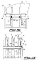
figure 12 shows a front view of the second apparatus during a fourth operating step of the process; and -
figure 13 shows a partial side view of the apparatus offigure 12 . -
Figure 1 shows a frameless window comprising a pane ofglass 1 and twoholders 2. Theholders 2 are generally in the form of elongate channels, i.e. with walls either side of an elongate slot, and so have a U-shaped cross-section. The ends of the channel are open. Each holder normally has a leg or similar appendage (shown infigures 3 to 5 ) extending downwards from the holder (in the normal orientation as shown infigure 1 ) to act as a coupling member for attaching the holder to a window lift mechanism (not shown). The holders are normally made of plastic. - Still referring to
figure 1 , it is seen that the frameless window according to the present invention comprises in a known way a transparent pane, in particular aglass pane 1, generally bent inwards, the lower edge of which is inserted in the slot of one ormore holders 2 which are suitable for supportingpane 1 and are provided with coupling members (not shown in the figures) for the mechanical connection to lifting devices, for example arranged in the door of a motor vehicle. - Referring to
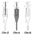
figures 2 to 4 , it is seen that the lower edge ofpane 1 is separated from the walls ofslot 3 ofholders 2 and is joined thereto by means of one or more layers of afirst adhesive 4 applied close to the lateral ends ofslot 3, wherein at least one layer of asecond adhesive 5 is applied inslot 3 between the layers of thefirst adhesive 4. A layer ofprimer 6 can be applied on the two faces of the lower edge ofpane 1 before applying the layers ofadhesive - The
first adhesive 4 is a hotmelt polyurethane adhesive, while thesecond adhesive 5 is a two-component polyurethane adhesive which can be applied at room temperature. The viscosity and the elastic modulus of thefirst adhesive 4 are higher than the viscosity and the elastic modulus, respectively, of thesecond adhesive 5, while the cure time of thefirst adhesive 4 is shorter than the cure time of thesecond adhesive 5. - Referring to
figure 5 , it is seen that the width ofslots 3 ofholders 2 is at least twice the thickness ofpane 1, so that the latter can be arranged in a variable position within a tolerance zone 7 (shown with broken lines) separated and distant from the inner walls ofslots 3. In particular, with apane 1 having a thickness comprised between 3 and 6 mm, the average width of thetolerance zone 7 is comprised between 6 and 10 mm, while the average width ofslot 3 is comprised between 8 and 14 mm. Thetolerance zone 7 further includes 1 mm of space downwards, while the average distance between the lower border of thetolerance zone 7 and the bottom ofslot 3 is comprised between 1 and 3 mm. The depth ofslot 3 is greater than 10 mm, in particular comprised between 31 and 33 mm. - Referring to
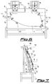
figures 6 and 7 , it is seen that in a first operating step of the process according to the present invention,pane 1, already provided withprimer 6, is arranged in a vertical or inclined position with the lower edge turned upwards on the first apparatus of the system according to the present invention, which comprises in a known way a plurality ofreference supports 8 arranged on a work-table 9. The ends of these reference supports 8 contactingpane 1 are arranged in determined points which are in the same position in space of reference points employed for mounting the window in a motor vehicle. In particular, fourreference supports 8 are arranged on work-table 9 in positions corresponding to the four corners ofpane 1. The work-table 9 comprises a plurality ofrollers 10 which contain laterally or support from the bottom the edges ofpane 1. One ormore pushers 11 are mounted on work-table 9 for urgingpane 1 againstrollers 10. In particular, afirst pusher 11 is arranged on the upper portion of work-table 9 and asecond pusher 11 is arranged on one side of work-table 9. A plurality ofsuction caps 12 are mounted on work-table 9 for pullingpane 1 against thereference supports 8. Twomobile supports holders 2 toward the lower edge, turned upwards, ofpane 1. The mobile supports 13, 14 are also provided with a plurality of reference supports and with alever vice 15 for locking in adetermined position holders 2 on these reference supports. The mobile supports 13, 14 can be driven by pneumatic pistons along aplane 16 tangent to the lower edge, turned upwards, ofpane 1, whichplane 16 forms an angle lower than 20° with work-table 9. Work-table 9 is inclined so that aplane 17 tangent to the upper edge turned downwards ofpane 1 forms an angle lower than 30°, in particular lower than 5°, with a vertical plane. Work-table 9 forms in turn an angle lower than 30° with a vertical plane. - Referring to
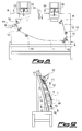
figures 8 and 9 , it is seen that in a second operating step of the process according to thepresent invention pane 1 is locked bypushers 11 and bysuction cups 12 on work-table 9, whileholders 2 are locked on the mobile supports 13, 14 by thelever vices 15. - Referring to
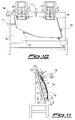
figures 10 and 11 , it is seen that in a third operating step of the process according to thepresent invention holders 2 are moved downwards towardpane 1 by the mobile supports 13, 14, so thatholders 2 are inserted astride the lower edge ofpane 1, after which the layers of the first adhesive 4 (shown with broken lines infigure 10 ), heated at a temperature comprised between 110 and 130 °C, are applied to the lateral ends ofslots 3 ofholders 2 by means of aheating applicator 18 provided with a curved nozzle, so as to easily reach the edges ofslots 3 arranged behindpane 1. Aprotective screen 19 suitable to coverpane 1, thereby leavingholders 2 uncovered, is arranged ontopane 1 before the application of thefirst adhesive 4. When thefirst adhesive 4 has reached a suitable cure time, i.e. when thefirst adhesive 4 can firmly supportholders 2 in their position with respect topane 1, thelever vices 15 are opened, the mobile supports 13, 14 are lifted,screen 19 is removed andpane 1 is separated from work-table 9.
Referring tofigures 12 and 13 , it is seen that in a fourth operating step of the process according to thepresent invention pane 1 provided withholders 2 is arranged with the lower edge turned downwards on acarriage 20 of the second apparatus of the system according to the present invention, which comprises a series ofcarriages 20 suitable for moving horizontally in a direction substantially perpendicular topane 1. For this purpose,carriages 20 are fixed to a conveying device comprising one ormore chains 21 driven by anelectric motor 22 by means oftoothed wheels 23, so that a first half ofcarriages 20 can run in a longitudinal direction, while the second half ofcarriages 20 runs under the first half in the opposite direction. Eachcarriage 20 comprises a plurality ofvertical supports 24, for example two pairs of bars, between which onepane 1 is arranged. Eachcarriage 20 also comprises a plurality ofrollers 25 whichsupport pane 1, thereby allowing a transversal sliding thereof with respect tocarriage 20. The vertical supports 24 are arranged between theholders 2 fixed topane 1. Aprotective sheath 26, for example a rubber glove, is put onholders 2, after which a mixingapplicator 27 pours from the top the second adhesive 5 (shown with broken lines infigure 12 ) intoslot 3 ofholders 2 ofpane 1 on thefirst carriage 20 arranged at the beginning of the series of carriages, untilslot 3 is filled with thesecond adhesive 5, which is contained laterally inslot 3 by the two layers of thefirst adhesive 4 arranged at the lateral ends ofslot 3. At the end of the application of thesecond adhesive 5,carriage 20 is moved longitudinally, so that a free carriage is arranged at the beginning of the series for receiving a new pane.
Claims (18)
- Frameless window (1, 2), in particular a mobile window for motor vehicles which comprises a transparent pane (1) and one or more holders (2), the holders being in the form of elongate channels with walls either side of an elongate slot (3), and so have a U-shaped cross-section, wherein the lower edge of the pane (1) is fixed in the slot (3) of the one or more holders (2) by means of two adhesives (4, 5), characterized in that the lower edge of the pane (1) is joined to the walls of the slot (3) of the holders (2) by means of one or more layers of a first adhesive (4) applied close to both lateral ends of the slot (3), wherein at least one layer of a second adhesive (5) is applied in the slot (3) of the holders (2) between the layers of the first adhesive (4) in liquid form without leaking, the second adhesive being contained laterally by the layers of the first adhesive.
- Window according to the previous claim, characterized in that the pane (1) is arranged in a variable position within a tolerance zone (7) separated and distant from the inner walls of the slot (3).
- Window according to one of the previous claims, characterized in that the first adhesive (4) is a hotmelt polyurethane adhesive.
- Window according to one of the previous claims, characterized in that the second adhesive (5) is a two-component polyurethane adhesive.
- Window according to the previous claim, characterized in that the second adhesive (5) can be applied at room temperature.
- Window according to one of the previous claims, characterized in that the viscosity of the first adhesive (4) is higher than the viscosity of the second adhesive (5).
- Window according to one of the previous claims, characterized in that the elastic modulus of the first adhesive (4) is higher than the elastic modulus of the second adhesive (5).
- Window according to one of the previous claims, characterized in that the cure time of the first adhesive (4) is shorter than the cure time of the second adhesive (5).
- Process for manufacturing frameless windows (1, 2), in particular a mobile window for motor vehicles which comprise a transparent pane (1) and one or more holders (2), the holders being in the form of elongate channels with walls either side of an elongate slot (3), and so have a U-shaped cross-section, wherein the lower edge of the pane is fixed in the slot (3) of the one or more holders (2) by means of two adhesives (4, 5), characterized in that it comprises the following operating steps:- arranging the lower edge of the pane (1) in the slot (3) of the holders (2);- applying one or more layers of a first adhesive (4) close to both lateral ends of the slot (3) of the holders (2);- applying at least one layer of a second adhesive (5) in the slot (3) of the holders (2) between the layers of the first adhesive (4) in liquid form without leaking, the second adhesive being contained laterally by the layers of the first adhesive.
- Process according to the previous claim, characterized in that the first adhesive (4) is a hotmelt polyurethane adhesive.
- Process according to the previous claim, characterized in that the first adhesive (4) is applied at a temperature comprised between 110 and 130 °C.
- Process according to one of claims 9 to 11, characterized in that the lower edge of the pane (1) is turned upwards when the first adhesive (4) is applied.
- Process according to one of claims 9 to 12, characterized in that the second adhesive (5) is a two-component polyurethane adhesive.
- Process according to the previous claim, characterized in that the second adhesive (5) is applied at room temperature.
- Process according to one of claims 9 to 14, characterized in that the lower edge of the pane (1) is turned downwards when the second adhesive (5) is applied.
- Process according to one of claims 9 to 15, characterized in that the viscosity of the first adhesive (4) is higher than the viscosity of the second adhesive (5).
- Process according to one of claims 9 to 16, characterized in that the elastic modulus of the first adhesive (4) is higher than the elastic modulus of the second adhesive (5).
- Process according to one of claims 9 to 17, characterized in that the cure time of the first adhesive (4) is shorter than the cure time of the second adhesive (5).
Priority Applications (1)
| Application Number | Priority Date | Filing Date | Title |
|---|---|---|---|
| EP07857801A EP2102440B1 (en) | 2006-12-19 | 2007-12-19 | Frameless window and process for its manufacture |
Applications Claiming Priority (3)
| Application Number | Priority Date | Filing Date | Title |
|---|---|---|---|
| EP06425847A EP1936088A1 (en) | 2006-12-19 | 2006-12-19 | Frameless window and process for its manufacture |
| PCT/EP2007/064178 WO2008074819A1 (en) | 2006-12-19 | 2007-12-19 | Frameless window and process for its manufacture |
| EP07857801A EP2102440B1 (en) | 2006-12-19 | 2007-12-19 | Frameless window and process for its manufacture |
Publications (2)
| Publication Number | Publication Date |
|---|---|
| EP2102440A1 EP2102440A1 (en) | 2009-09-23 |
| EP2102440B1 true EP2102440B1 (en) | 2011-10-12 |
Family
ID=38008265
Family Applications (2)
| Application Number | Title | Priority Date | Filing Date |
|---|---|---|---|
| EP06425847A Withdrawn EP1936088A1 (en) | 2006-12-19 | 2006-12-19 | Frameless window and process for its manufacture |
| EP07857801A Not-in-force EP2102440B1 (en) | 2006-12-19 | 2007-12-19 | Frameless window and process for its manufacture |
Family Applications Before (1)
| Application Number | Title | Priority Date | Filing Date |
|---|---|---|---|
| EP06425847A Withdrawn EP1936088A1 (en) | 2006-12-19 | 2006-12-19 | Frameless window and process for its manufacture |
Country Status (6)
| Country | Link |
|---|---|
| US (1) | US8171682B2 (en) |
| EP (2) | EP1936088A1 (en) |
| CN (1) | CN101563516B (en) |
| AT (1) | ATE528476T1 (en) |
| BR (1) | BRPI0721142B1 (en) |
| WO (1) | WO2008074819A1 (en) |
Cited By (1)
| Publication number | Priority date | Publication date | Assignee | Title |
|---|---|---|---|---|
| EP4733097A1 (en) * | 2024-10-22 | 2026-04-29 | MAN Truck & Bus SE | Device for facilitating the insertion of a glass pane |
Families Citing this family (14)
| Publication number | Priority date | Publication date | Assignee | Title |
|---|---|---|---|---|
| EP1935558A1 (en) * | 2006-12-19 | 2008-06-25 | Pilkington Italia S.p.A. | System and process for manufacturing frameless windows |
| DE202010009720U1 (en) * | 2009-03-17 | 2011-02-10 | Pilkington Italia S.P.A. | Vehicle trim with a trim strip mounted on it |
| KR102071428B1 (en) * | 2015-12-08 | 2020-01-30 | 쌩-고벵 글래스 프랑스 | Apparatus comprising a paint and at least one lifting rail, method for manufacturing thereof and uses thereof |
| US10801252B2 (en) | 2016-06-25 | 2020-10-13 | Alexander Uskolovsky | Window assembly |
| US9970226B2 (en) * | 2016-10-05 | 2018-05-15 | GM Global Technology Operations LLC | Vehicle window assembly |
| JP7147484B2 (en) * | 2017-12-08 | 2022-10-05 | Agc株式会社 | Window glass with holder and manufacturing method thereof |
| PL3724436T3 (en) | 2017-12-12 | 2022-01-31 | Saint-Gobain Glass France | Support member for a raisable and lowerable vehicle side panel |
| EP3724437B1 (en) * | 2017-12-12 | 2023-12-13 | Saint-Gobain Glass France | Vehicle side panel with retaining element mounted on one side |
| JP7084999B2 (en) * | 2017-12-12 | 2022-06-15 | サン-ゴバン グラス フランス | Holding element for side windows of vehicles that can rise and fall |
| JP7402416B2 (en) * | 2020-03-23 | 2023-12-21 | Agc株式会社 | window glass with holder |
| JP7443916B2 (en) * | 2020-04-30 | 2024-03-06 | Agc株式会社 | Method for manufacturing window glass with holder and device for manufacturing window glass with holder |
| FR3122687B1 (en) | 2021-05-07 | 2024-05-24 | Saint Gobain | METHOD FOR MANUFACTURING SLIDING GLAZING AND Sliding GLAZING |
| FR3122686B1 (en) | 2021-05-07 | 2023-04-28 | Saint Gobain | METHOD FOR MANUFACTURING SLIDING GLAZING AND SLIDING GLAZING |
| FR3125080A1 (en) | 2021-07-08 | 2023-01-13 | Saint-Gobain Glass France | Movable vehicle glazing support and method for adjusting the inclination of a movable glazing |
Family Cites Families (37)
| Publication number | Priority date | Publication date | Assignee | Title |
|---|---|---|---|---|
| US3832274A (en) * | 1973-06-06 | 1974-08-27 | Lord Corp | Fast curing adhesives |
| JPS551261Y2 (en) * | 1975-08-20 | 1980-01-14 | ||
| DE3431391A1 (en) | 1984-08-25 | 1986-03-13 | Bayerische Motoren Werke AG, 8000 München | WINDOW WINDOW FOR MOTOR VEHICLES WITH A RAIL FASTENED TO IT |
| US4803257A (en) * | 1987-04-24 | 1989-02-07 | Ashland Oil, Inc. | Flexible, structural polyurethane adhesives with initial pressure sensitive adhesive performance |
| US4987699A (en) * | 1989-08-24 | 1991-01-29 | Gold Peter N | Mounting for an automotive window panel |
| DE3932724A1 (en) | 1989-09-30 | 1991-04-18 | Bayerische Motoren Werke Ag | Seal between vehicle frameless door window and adjacent window - is fixed to one window and consists of reinforcing section completely embedded in elastomeric sealing element |
| DE4203364C2 (en) | 1992-02-06 | 1993-12-23 | Daimler Benz Ag | Sealing strip for side windows of motor vehicles without a B-pillar |
| DE4336107C2 (en) | 1993-10-22 | 1995-09-21 | Daimler Benz Ag | Double-glazed window lifter unit |
| DE4340363A1 (en) | 1993-11-26 | 1995-06-01 | Griwe Innovative Umformtechnik | Mounting automobile side window pane |
| JP3273690B2 (en) * | 1994-03-24 | 2002-04-08 | 株式会社ニフコ | Glass holder |
| JPH09323542A (en) * | 1996-06-07 | 1997-12-16 | Nifco Inc | Glass holder |
| DE19728580A1 (en) | 1996-07-16 | 1998-01-22 | Volkswagen Ag | Rotary table, especially to hold car doors during manufacture |
| FR2762350B1 (en) | 1997-04-22 | 1999-07-09 | Rockwell Lvs | METHOD FOR ADJUSTING THE ANGULAR POSITION OF A DOOR GLASS, PARTICULARLY FOR A VEHICLE, AND ASSEMBLY OBTAINED BY THIS METHOD |
| DE19720075A1 (en) | 1997-05-14 | 1998-11-19 | Sekurit Saint Gobain Deutsch | Door windows for motor vehicles with a retractable laminated glass pane |
| SE9704468D0 (en) | 1997-12-01 | 1997-12-01 | Hans P Lindblad | Device for and method of mutually positioning two objects |
| DE19808916A1 (en) | 1998-03-03 | 1999-09-09 | Delphi Automotive Systems Gmbh | Method for attaching window pane to window operating drive in vehicle |
| DE19836077C2 (en) * | 1998-07-30 | 2000-05-31 | Brose Fahrzeugteile | Device for connecting a window pane to a window regulator |
| DE19902059C2 (en) | 1999-01-20 | 2000-06-21 | Audi Ag | Disc holder |
| US6349504B1 (en) * | 1999-10-18 | 2002-02-26 | Elco Textron, Inc. | Window lift bracket |
| FR2804650B1 (en) | 2000-02-09 | 2002-04-05 | Renault | DEVICE FOR PLACING A HIGHLY BOMBED WORKPIECE IN A PREDETERMINED POSITION, AND METHOD APPLIED TO THIS DEVICE |
| BE1013572A4 (en) * | 2000-06-23 | 2002-04-02 | Glaverbel | Windows mobile pre-adjusted position. |
| DE10039841A1 (en) * | 2000-08-10 | 2002-02-28 | Meritor Automotive Gmbh | Device for connecting a retractable and extendable motor vehicle window pane to a drive element |
| DE10044845B4 (en) | 2000-09-11 | 2004-06-09 | Brose Fahrzeugteile Gmbh & Co. Kommanditgesellschaft, Coburg | Vehicle door with a cable window lifter adjustable for a frameless window pane |
| DE10049768C2 (en) | 2000-10-02 | 2002-08-14 | Brose Fahrzeugteile | Device for connecting a window pane to the guide device of a window lifter |
| US6425207B1 (en) * | 2000-12-20 | 2002-07-30 | Muncy Corporation | Window regulator with window panel clamp unit |
| EP1239016A1 (en) | 2001-03-08 | 2002-09-11 | Sika AG, vorm. Kaspar Winkler & Co. | Elastic meth (acrylic) adhesive compositions |
| WO2002081841A1 (en) * | 2001-04-03 | 2002-10-17 | James Hardie Research Pty Limited | Fiber cement siding planks, methods of making and installing |
| US6966149B2 (en) * | 2003-03-27 | 2005-11-22 | Fenelon Paul J | Window bracket for a window lift mechanism |
| DE10237756A1 (en) | 2002-08-17 | 2004-03-04 | Saint-Gobain Sekurit Deutschland Gmbh & Co. Kg | Method for producing a height-adjustable vehicle window and height-adjustable vehicle window |
| ATE271477T1 (en) | 2002-09-30 | 2004-08-15 | Eftec Europe Holding Ag | METHOD AND FASTENING SYSTEM FOR MOUNTING A VEHICLE WINDOW ON A SUPPORT FRAME, A VEHICLE WINDOW AND A VEHICLE HAVING SUCH A WINDOW |
| DE10314400A1 (en) * | 2003-03-28 | 2004-10-21 | Pilkington Automotive Deutschland Gmbh | Method and installation for treating the glass panes of an asymmetrical pair of glass panes |
| FR2857716B1 (en) * | 2003-07-18 | 2005-09-09 | Arvinmeritor Light Vehicle Sys | WINDOW CABLE TENSIONER |
| DE102004015052A1 (en) | 2004-03-25 | 2005-10-13 | Bayerische Motoren Werke Ag | Pre-assembly table for a vehicle window pane, for the application of sealing and adhesive masses and positioning for installation, has computer-controlled lower supports and side holders according to the pane configuration |
| EP1617028B1 (en) | 2004-07-16 | 2008-09-17 | Brose Fahrzeugteile GmbH & Co. KG, Coburg | Window regulator for a motor vehicle door |
| EP1773583A1 (en) * | 2004-07-30 | 2007-04-18 | Mannington Mills, Inc. | Flooring products and methods of making the same |
| US20060048452A1 (en) * | 2004-09-03 | 2006-03-09 | Sweeney John A | Flexible mounting bracket for vehicle window panel |
| EP1935558A1 (en) * | 2006-12-19 | 2008-06-25 | Pilkington Italia S.p.A. | System and process for manufacturing frameless windows |
-
2006
- 2006-12-19 EP EP06425847A patent/EP1936088A1/en not_active Withdrawn
-
2007
- 2007-12-19 US US12/519,695 patent/US8171682B2/en active Active
- 2007-12-19 BR BRPI0721142-2A patent/BRPI0721142B1/en not_active IP Right Cessation
- 2007-12-19 CN CN2007800472833A patent/CN101563516B/en not_active Expired - Fee Related
- 2007-12-19 EP EP07857801A patent/EP2102440B1/en not_active Not-in-force
- 2007-12-19 WO PCT/EP2007/064178 patent/WO2008074819A1/en not_active Ceased
- 2007-12-19 AT AT07857801T patent/ATE528476T1/en not_active IP Right Cessation
Cited By (1)
| Publication number | Priority date | Publication date | Assignee | Title |
|---|---|---|---|---|
| EP4733097A1 (en) * | 2024-10-22 | 2026-04-29 | MAN Truck & Bus SE | Device for facilitating the insertion of a glass pane |
Also Published As
| Publication number | Publication date |
|---|---|
| BRPI0721142A2 (en) | 2014-04-01 |
| EP2102440A1 (en) | 2009-09-23 |
| WO2008074819A1 (en) | 2008-06-26 |
| EP1936088A1 (en) | 2008-06-25 |
| CN101563516A (en) | 2009-10-21 |
| US20100037543A1 (en) | 2010-02-18 |
| US8171682B2 (en) | 2012-05-08 |
| ATE528476T1 (en) | 2011-10-15 |
| CN101563516B (en) | 2013-02-27 |
| BRPI0721142B1 (en) | 2019-04-30 |
Similar Documents
| Publication | Publication Date | Title |
|---|---|---|
| US8171682B2 (en) | Frameless window and process for its manufacture | |
| US8146645B2 (en) | System and process for manufacturing frameless windows | |
| KR102555121B1 (en) | Sliding laminated glazing with internal projections | |
| CN108260353B (en) | Sliding laminated glazing unit with internal protrusions | |
| RU2736897C1 (en) | Vehicle side window with retaining element installed on one side | |
| US20100304070A1 (en) | Glazing | |
| EP1936087B1 (en) | Frameless window for passenger vehicle | |
| EP1935557B1 (en) | Process and apparatus for manufacturing frameless windows | |
| CN115916562B (en) | Sliding laminated glazing with inner recess and method for manufacturing such glazing | |
| EP1567381B1 (en) | Sealing, guiding and trimming strip arrangements and methods of making them | |
| US20240240504A1 (en) | Method for manufacturing a sliding glazing unit, and sliding glazing unit |
Legal Events
| Date | Code | Title | Description |
|---|---|---|---|
| PUAI | Public reference made under article 153(3) epc to a published international application that has entered the european phase |
Free format text: ORIGINAL CODE: 0009012 |
|
| 17P | Request for examination filed |
Effective date: 20090720 |
|
| AK | Designated contracting states |
Kind code of ref document: A1 Designated state(s): AT BE BG CH CY CZ DE DK EE ES FI FR GB GR HU IE IS IT LI LT LU LV MC MT NL PL PT RO SE SI SK TR |
|
| DAX | Request for extension of the european patent (deleted) | ||
| 17Q | First examination report despatched |
Effective date: 20100413 |
|
| GRAP | Despatch of communication of intention to grant a patent |
Free format text: ORIGINAL CODE: EPIDOSNIGR1 |
|
| GRAS | Grant fee paid |
Free format text: ORIGINAL CODE: EPIDOSNIGR3 |
|
| GRAA | (expected) grant |
Free format text: ORIGINAL CODE: 0009210 |
|
| AK | Designated contracting states |
Kind code of ref document: B1 Designated state(s): AT BE BG CH CY CZ DE DK EE ES FI FR GB GR HU IE IS IT LI LT LU LV MC MT NL PL PT RO SE SI SK TR |
|
| REG | Reference to a national code |
Ref country code: GB Ref legal event code: FG4D |
|
| REG | Reference to a national code |
Ref country code: CH Ref legal event code: EP |
|
| REG | Reference to a national code |
Ref country code: IE Ref legal event code: FG4D |
|
| REG | Reference to a national code |
Ref country code: DE Ref legal event code: R096 Ref document number: 602007017879 Country of ref document: DE Effective date: 20111215 |
|
| REG | Reference to a national code |
Ref country code: NL Ref legal event code: VDEP Effective date: 20111012 |
|
| LTIE | Lt: invalidation of european patent or patent extension |
Effective date: 20111012 |
|
| REG | Reference to a national code |
Ref country code: AT Ref legal event code: MK05 Ref document number: 528476 Country of ref document: AT Kind code of ref document: T Effective date: 20111012 |
|
| PG25 | Lapsed in a contracting state [announced via postgrant information from national office to epo] |
Ref country code: BE Free format text: LAPSE BECAUSE OF FAILURE TO SUBMIT A TRANSLATION OF THE DESCRIPTION OR TO PAY THE FEE WITHIN THE PRESCRIBED TIME-LIMIT Effective date: 20111012 Ref country code: IS Free format text: LAPSE BECAUSE OF FAILURE TO SUBMIT A TRANSLATION OF THE DESCRIPTION OR TO PAY THE FEE WITHIN THE PRESCRIBED TIME-LIMIT Effective date: 20120212 Ref country code: LT Free format text: LAPSE BECAUSE OF FAILURE TO SUBMIT A TRANSLATION OF THE DESCRIPTION OR TO PAY THE FEE WITHIN THE PRESCRIBED TIME-LIMIT Effective date: 20111012 |
|
| PG25 | Lapsed in a contracting state [announced via postgrant information from national office to epo] |
Ref country code: NL Free format text: LAPSE BECAUSE OF FAILURE TO SUBMIT A TRANSLATION OF THE DESCRIPTION OR TO PAY THE FEE WITHIN THE PRESCRIBED TIME-LIMIT Effective date: 20111012 Ref country code: PT Free format text: LAPSE BECAUSE OF FAILURE TO SUBMIT A TRANSLATION OF THE DESCRIPTION OR TO PAY THE FEE WITHIN THE PRESCRIBED TIME-LIMIT Effective date: 20120213 Ref country code: LV Free format text: LAPSE BECAUSE OF FAILURE TO SUBMIT A TRANSLATION OF THE DESCRIPTION OR TO PAY THE FEE WITHIN THE PRESCRIBED TIME-LIMIT Effective date: 20111012 Ref country code: GR Free format text: LAPSE BECAUSE OF FAILURE TO SUBMIT A TRANSLATION OF THE DESCRIPTION OR TO PAY THE FEE WITHIN THE PRESCRIBED TIME-LIMIT Effective date: 20120113 Ref country code: SI Free format text: LAPSE BECAUSE OF FAILURE TO SUBMIT A TRANSLATION OF THE DESCRIPTION OR TO PAY THE FEE WITHIN THE PRESCRIBED TIME-LIMIT Effective date: 20111012 Ref country code: SE Free format text: LAPSE BECAUSE OF FAILURE TO SUBMIT A TRANSLATION OF THE DESCRIPTION OR TO PAY THE FEE WITHIN THE PRESCRIBED TIME-LIMIT Effective date: 20111012 |
|
| PG25 | Lapsed in a contracting state [announced via postgrant information from national office to epo] |
Ref country code: CY Free format text: LAPSE BECAUSE OF FAILURE TO SUBMIT A TRANSLATION OF THE DESCRIPTION OR TO PAY THE FEE WITHIN THE PRESCRIBED TIME-LIMIT Effective date: 20111012 |
|
| PG25 | Lapsed in a contracting state [announced via postgrant information from national office to epo] |
Ref country code: MC Free format text: LAPSE BECAUSE OF NON-PAYMENT OF DUE FEES Effective date: 20111231 Ref country code: CZ Free format text: LAPSE BECAUSE OF FAILURE TO SUBMIT A TRANSLATION OF THE DESCRIPTION OR TO PAY THE FEE WITHIN THE PRESCRIBED TIME-LIMIT Effective date: 20111012 Ref country code: SK Free format text: LAPSE BECAUSE OF FAILURE TO SUBMIT A TRANSLATION OF THE DESCRIPTION OR TO PAY THE FEE WITHIN THE PRESCRIBED TIME-LIMIT Effective date: 20111012 Ref country code: EE Free format text: LAPSE BECAUSE OF FAILURE TO SUBMIT A TRANSLATION OF THE DESCRIPTION OR TO PAY THE FEE WITHIN THE PRESCRIBED TIME-LIMIT Effective date: 20111012 Ref country code: BG Free format text: LAPSE BECAUSE OF FAILURE TO SUBMIT A TRANSLATION OF THE DESCRIPTION OR TO PAY THE FEE WITHIN THE PRESCRIBED TIME-LIMIT Effective date: 20120112 Ref country code: DK Free format text: LAPSE BECAUSE OF FAILURE TO SUBMIT A TRANSLATION OF THE DESCRIPTION OR TO PAY THE FEE WITHIN THE PRESCRIBED TIME-LIMIT Effective date: 20111012 |
|
| REG | Reference to a national code |
Ref country code: CH Ref legal event code: PL |
|
| PLBE | No opposition filed within time limit |
Free format text: ORIGINAL CODE: 0009261 |
|
| STAA | Information on the status of an ep patent application or granted ep patent |
Free format text: STATUS: NO OPPOSITION FILED WITHIN TIME LIMIT |
|
| PG25 | Lapsed in a contracting state [announced via postgrant information from national office to epo] |
Ref country code: RO Free format text: LAPSE BECAUSE OF FAILURE TO SUBMIT A TRANSLATION OF THE DESCRIPTION OR TO PAY THE FEE WITHIN THE PRESCRIBED TIME-LIMIT Effective date: 20111012 Ref country code: IT Free format text: LAPSE BECAUSE OF FAILURE TO SUBMIT A TRANSLATION OF THE DESCRIPTION OR TO PAY THE FEE WITHIN THE PRESCRIBED TIME-LIMIT Effective date: 20111012 Ref country code: PL Free format text: LAPSE BECAUSE OF FAILURE TO SUBMIT A TRANSLATION OF THE DESCRIPTION OR TO PAY THE FEE WITHIN THE PRESCRIBED TIME-LIMIT Effective date: 20111012 |
|
| 26N | No opposition filed |
Effective date: 20120713 |
|
| GBPC | Gb: european patent ceased through non-payment of renewal fee |
Effective date: 20120112 |
|
| REG | Reference to a national code |
Ref country code: IE Ref legal event code: MM4A |
|
| PG25 | Lapsed in a contracting state [announced via postgrant information from national office to epo] |
Ref country code: IE Free format text: LAPSE BECAUSE OF NON-PAYMENT OF DUE FEES Effective date: 20111219 Ref country code: GB Free format text: LAPSE BECAUSE OF NON-PAYMENT OF DUE FEES Effective date: 20120112 Ref country code: CH Free format text: LAPSE BECAUSE OF NON-PAYMENT OF DUE FEES Effective date: 20111231 Ref country code: LI Free format text: LAPSE BECAUSE OF NON-PAYMENT OF DUE FEES Effective date: 20111231 |
|
| REG | Reference to a national code |
Ref country code: DE Ref legal event code: R097 Ref document number: 602007017879 Country of ref document: DE Effective date: 20120713 |
|
| PG25 | Lapsed in a contracting state [announced via postgrant information from national office to epo] |
Ref country code: AT Free format text: LAPSE BECAUSE OF FAILURE TO SUBMIT A TRANSLATION OF THE DESCRIPTION OR TO PAY THE FEE WITHIN THE PRESCRIBED TIME-LIMIT Effective date: 20111012 |
|
| PG25 | Lapsed in a contracting state [announced via postgrant information from national office to epo] |
Ref country code: MT Free format text: LAPSE BECAUSE OF FAILURE TO SUBMIT A TRANSLATION OF THE DESCRIPTION OR TO PAY THE FEE WITHIN THE PRESCRIBED TIME-LIMIT Effective date: 20111012 |
|
| PG25 | Lapsed in a contracting state [announced via postgrant information from national office to epo] |
Ref country code: ES Free format text: LAPSE BECAUSE OF FAILURE TO SUBMIT A TRANSLATION OF THE DESCRIPTION OR TO PAY THE FEE WITHIN THE PRESCRIBED TIME-LIMIT Effective date: 20120123 |
|
| PG25 | Lapsed in a contracting state [announced via postgrant information from national office to epo] |
Ref country code: LU Free format text: LAPSE BECAUSE OF NON-PAYMENT OF DUE FEES Effective date: 20111219 |
|
| PG25 | Lapsed in a contracting state [announced via postgrant information from national office to epo] |
Ref country code: FI Free format text: LAPSE BECAUSE OF FAILURE TO SUBMIT A TRANSLATION OF THE DESCRIPTION OR TO PAY THE FEE WITHIN THE PRESCRIBED TIME-LIMIT Effective date: 20111012 |
|
| PG25 | Lapsed in a contracting state [announced via postgrant information from national office to epo] |
Ref country code: TR Free format text: LAPSE BECAUSE OF FAILURE TO SUBMIT A TRANSLATION OF THE DESCRIPTION OR TO PAY THE FEE WITHIN THE PRESCRIBED TIME-LIMIT Effective date: 20111012 |
|
| PG25 | Lapsed in a contracting state [announced via postgrant information from national office to epo] |
Ref country code: HU Free format text: LAPSE BECAUSE OF FAILURE TO SUBMIT A TRANSLATION OF THE DESCRIPTION OR TO PAY THE FEE WITHIN THE PRESCRIBED TIME-LIMIT Effective date: 20111012 |
|
| REG | Reference to a national code |
Ref country code: FR Ref legal event code: PLFP Year of fee payment: 9 |
|
| REG | Reference to a national code |
Ref country code: FR Ref legal event code: PLFP Year of fee payment: 10 |
|
| REG | Reference to a national code |
Ref country code: FR Ref legal event code: PLFP Year of fee payment: 11 |
|
| P01 | Opt-out of the competence of the unified patent court (upc) registered |
Effective date: 20230516 |
|
| PGFP | Annual fee paid to national office [announced via postgrant information from national office to epo] |
Ref country code: FR Payment date: 20231219 Year of fee payment: 17 Ref country code: DE Payment date: 20231214 Year of fee payment: 17 |
|
| REG | Reference to a national code |
Ref country code: DE Ref legal event code: R119 Ref document number: 602007017879 Country of ref document: DE |
|
| PG25 | Lapsed in a contracting state [announced via postgrant information from national office to epo] |
Ref country code: DE Free format text: LAPSE BECAUSE OF NON-PAYMENT OF DUE FEES Effective date: 20250701 |
|
| PG25 | Lapsed in a contracting state [announced via postgrant information from national office to epo] |
Ref country code: FR Free format text: LAPSE BECAUSE OF NON-PAYMENT OF DUE FEES Effective date: 20241231 |