EP2102058B1 - Fuel supply apparatus of liquefied gas carrier and fuel supply method thereof - Google Patents
Fuel supply apparatus of liquefied gas carrier and fuel supply method thereof Download PDFInfo
- Publication number
- EP2102058B1 EP2102058B1 EP07851606A EP07851606A EP2102058B1 EP 2102058 B1 EP2102058 B1 EP 2102058B1 EP 07851606 A EP07851606 A EP 07851606A EP 07851606 A EP07851606 A EP 07851606A EP 2102058 B1 EP2102058 B1 EP 2102058B1
- Authority
- EP
- European Patent Office
- Prior art keywords
- fuel
- gas
- valve
- propulsion system
- compressor
- Prior art date
- Legal status (The legal status is an assumption and is not a legal conclusion. Google has not performed a legal analysis and makes no representation as to the accuracy of the status listed.)
- Active
Links
Images




Classifications
-
- B—PERFORMING OPERATIONS; TRANSPORTING
- B63—SHIPS OR OTHER WATERBORNE VESSELS; RELATED EQUIPMENT
- B63J—AUXILIARIES ON VESSELS
- B63J99/00—Subject matter not provided for in other groups of this subclass
-
- B—PERFORMING OPERATIONS; TRANSPORTING
- B63—SHIPS OR OTHER WATERBORNE VESSELS; RELATED EQUIPMENT
- B63H—MARINE PROPULSION OR STEERING
- B63H21/00—Use of propulsion power plant or units on vessels
- B63H21/12—Use of propulsion power plant or units on vessels the vessels being motor-driven
- B63H21/16—Use of propulsion power plant or units on vessels the vessels being motor-driven relating to gas turbines
-
- B—PERFORMING OPERATIONS; TRANSPORTING
- B63—SHIPS OR OTHER WATERBORNE VESSELS; RELATED EQUIPMENT
- B63H—MARINE PROPULSION OR STEERING
- B63H21/00—Use of propulsion power plant or units on vessels
- B63H21/12—Use of propulsion power plant or units on vessels the vessels being motor-driven
-
- F—MECHANICAL ENGINEERING; LIGHTING; HEATING; WEAPONS; BLASTING
- F17—STORING OR DISTRIBUTING GASES OR LIQUIDS
- F17C—VESSELS FOR CONTAINING OR STORING COMPRESSED, LIQUEFIED OR SOLIDIFIED GASES; FIXED-CAPACITY GAS-HOLDERS; FILLING VESSELS WITH, OR DISCHARGING FROM VESSELS, COMPRESSED, LIQUEFIED, OR SOLIDIFIED GASES
- F17C3/00—Vessels not under pressure
- F17C3/02—Vessels not under pressure with provision for thermal insulation
- F17C3/025—Bulk storage in barges or on ships
-
- B—PERFORMING OPERATIONS; TRANSPORTING
- B63—SHIPS OR OTHER WATERBORNE VESSELS; RELATED EQUIPMENT
- B63J—AUXILIARIES ON VESSELS
- B63J99/00—Subject matter not provided for in other groups of this subclass
- B63J2099/001—Burning of transported goods, e.g. fuel, boil-off or refuse
- B63J2099/003—Burning of transported goods, e.g. fuel, boil-off or refuse of cargo oil or fuel, or of boil-off gases, e.g. for propulsive purposes
-
- F—MECHANICAL ENGINEERING; LIGHTING; HEATING; WEAPONS; BLASTING
- F17—STORING OR DISTRIBUTING GASES OR LIQUIDS
- F17C—VESSELS FOR CONTAINING OR STORING COMPRESSED, LIQUEFIED OR SOLIDIFIED GASES; FIXED-CAPACITY GAS-HOLDERS; FILLING VESSELS WITH, OR DISCHARGING FROM VESSELS, COMPRESSED, LIQUEFIED, OR SOLIDIFIED GASES
- F17C2201/00—Vessel construction, in particular geometry, arrangement or size
- F17C2201/05—Size
- F17C2201/052—Size large (>1000 m3)
-
- F—MECHANICAL ENGINEERING; LIGHTING; HEATING; WEAPONS; BLASTING
- F17—STORING OR DISTRIBUTING GASES OR LIQUIDS
- F17C—VESSELS FOR CONTAINING OR STORING COMPRESSED, LIQUEFIED OR SOLIDIFIED GASES; FIXED-CAPACITY GAS-HOLDERS; FILLING VESSELS WITH, OR DISCHARGING FROM VESSELS, COMPRESSED, LIQUEFIED, OR SOLIDIFIED GASES
- F17C2205/00—Vessel construction, in particular mounting arrangements, attachments or identifications means
- F17C2205/01—Mounting arrangements
- F17C2205/0123—Mounting arrangements characterised by number of vessels
- F17C2205/013—Two or more vessels
-
- F—MECHANICAL ENGINEERING; LIGHTING; HEATING; WEAPONS; BLASTING
- F17—STORING OR DISTRIBUTING GASES OR LIQUIDS
- F17C—VESSELS FOR CONTAINING OR STORING COMPRESSED, LIQUEFIED OR SOLIDIFIED GASES; FIXED-CAPACITY GAS-HOLDERS; FILLING VESSELS WITH, OR DISCHARGING FROM VESSELS, COMPRESSED, LIQUEFIED, OR SOLIDIFIED GASES
- F17C2205/00—Vessel construction, in particular mounting arrangements, attachments or identifications means
- F17C2205/01—Mounting arrangements
- F17C2205/0123—Mounting arrangements characterised by number of vessels
- F17C2205/013—Two or more vessels
- F17C2205/0134—Two or more vessels characterised by the presence of fluid connection between vessels
- F17C2205/0142—Two or more vessels characterised by the presence of fluid connection between vessels bundled in parallel
-
- F—MECHANICAL ENGINEERING; LIGHTING; HEATING; WEAPONS; BLASTING
- F17—STORING OR DISTRIBUTING GASES OR LIQUIDS
- F17C—VESSELS FOR CONTAINING OR STORING COMPRESSED, LIQUEFIED OR SOLIDIFIED GASES; FIXED-CAPACITY GAS-HOLDERS; FILLING VESSELS WITH, OR DISCHARGING FROM VESSELS, COMPRESSED, LIQUEFIED, OR SOLIDIFIED GASES
- F17C2205/00—Vessel construction, in particular mounting arrangements, attachments or identifications means
- F17C2205/03—Fluid connections, filters, valves, closure means or other attachments
- F17C2205/0302—Fittings, valves, filters, or components in connection with the gas storage device
- F17C2205/0338—Pressure regulators
-
- F—MECHANICAL ENGINEERING; LIGHTING; HEATING; WEAPONS; BLASTING
- F17—STORING OR DISTRIBUTING GASES OR LIQUIDS
- F17C—VESSELS FOR CONTAINING OR STORING COMPRESSED, LIQUEFIED OR SOLIDIFIED GASES; FIXED-CAPACITY GAS-HOLDERS; FILLING VESSELS WITH, OR DISCHARGING FROM VESSELS, COMPRESSED, LIQUEFIED, OR SOLIDIFIED GASES
- F17C2221/00—Handled fluid, in particular type of fluid
- F17C2221/03—Mixtures
- F17C2221/032—Hydrocarbons
- F17C2221/033—Methane, e.g. natural gas, CNG, LNG, GNL, GNC, PLNG
-
- F—MECHANICAL ENGINEERING; LIGHTING; HEATING; WEAPONS; BLASTING
- F17—STORING OR DISTRIBUTING GASES OR LIQUIDS
- F17C—VESSELS FOR CONTAINING OR STORING COMPRESSED, LIQUEFIED OR SOLIDIFIED GASES; FIXED-CAPACITY GAS-HOLDERS; FILLING VESSELS WITH, OR DISCHARGING FROM VESSELS, COMPRESSED, LIQUEFIED, OR SOLIDIFIED GASES
- F17C2221/00—Handled fluid, in particular type of fluid
- F17C2221/03—Mixtures
- F17C2221/032—Hydrocarbons
- F17C2221/035—Propane butane, e.g. LPG, GPL
-
- F—MECHANICAL ENGINEERING; LIGHTING; HEATING; WEAPONS; BLASTING
- F17—STORING OR DISTRIBUTING GASES OR LIQUIDS
- F17C—VESSELS FOR CONTAINING OR STORING COMPRESSED, LIQUEFIED OR SOLIDIFIED GASES; FIXED-CAPACITY GAS-HOLDERS; FILLING VESSELS WITH, OR DISCHARGING FROM VESSELS, COMPRESSED, LIQUEFIED, OR SOLIDIFIED GASES
- F17C2223/00—Handled fluid before transfer, i.e. state of fluid when stored in the vessel or before transfer from the vessel
- F17C2223/01—Handled fluid before transfer, i.e. state of fluid when stored in the vessel or before transfer from the vessel characterised by the phase
- F17C2223/0146—Two-phase
- F17C2223/0153—Liquefied gas, e.g. LPG, GPL
-
- F—MECHANICAL ENGINEERING; LIGHTING; HEATING; WEAPONS; BLASTING
- F17—STORING OR DISTRIBUTING GASES OR LIQUIDS
- F17C—VESSELS FOR CONTAINING OR STORING COMPRESSED, LIQUEFIED OR SOLIDIFIED GASES; FIXED-CAPACITY GAS-HOLDERS; FILLING VESSELS WITH, OR DISCHARGING FROM VESSELS, COMPRESSED, LIQUEFIED, OR SOLIDIFIED GASES
- F17C2223/00—Handled fluid before transfer, i.e. state of fluid when stored in the vessel or before transfer from the vessel
- F17C2223/01—Handled fluid before transfer, i.e. state of fluid when stored in the vessel or before transfer from the vessel characterised by the phase
- F17C2223/0146—Two-phase
- F17C2223/0153—Liquefied gas, e.g. LPG, GPL
- F17C2223/0161—Liquefied gas, e.g. LPG, GPL cryogenic, e.g. LNG, GNL, PLNG
-
- F—MECHANICAL ENGINEERING; LIGHTING; HEATING; WEAPONS; BLASTING
- F17—STORING OR DISTRIBUTING GASES OR LIQUIDS
- F17C—VESSELS FOR CONTAINING OR STORING COMPRESSED, LIQUEFIED OR SOLIDIFIED GASES; FIXED-CAPACITY GAS-HOLDERS; FILLING VESSELS WITH, OR DISCHARGING FROM VESSELS, COMPRESSED, LIQUEFIED, OR SOLIDIFIED GASES
- F17C2223/00—Handled fluid before transfer, i.e. state of fluid when stored in the vessel or before transfer from the vessel
- F17C2223/03—Handled fluid before transfer, i.e. state of fluid when stored in the vessel or before transfer from the vessel characterised by the pressure level
- F17C2223/033—Small pressure, e.g. for liquefied gas
-
- F—MECHANICAL ENGINEERING; LIGHTING; HEATING; WEAPONS; BLASTING
- F17—STORING OR DISTRIBUTING GASES OR LIQUIDS
- F17C—VESSELS FOR CONTAINING OR STORING COMPRESSED, LIQUEFIED OR SOLIDIFIED GASES; FIXED-CAPACITY GAS-HOLDERS; FILLING VESSELS WITH, OR DISCHARGING FROM VESSELS, COMPRESSED, LIQUEFIED, OR SOLIDIFIED GASES
- F17C2227/00—Transfer of fluids, i.e. method or means for transferring the fluid; Heat exchange with the fluid
- F17C2227/01—Propulsion of the fluid
- F17C2227/0128—Propulsion of the fluid with pumps or compressors
- F17C2227/0157—Compressors
- F17C2227/0164—Compressors with specified compressor type, e.g. piston or impulsive type
-
- F—MECHANICAL ENGINEERING; LIGHTING; HEATING; WEAPONS; BLASTING
- F17—STORING OR DISTRIBUTING GASES OR LIQUIDS
- F17C—VESSELS FOR CONTAINING OR STORING COMPRESSED, LIQUEFIED OR SOLIDIFIED GASES; FIXED-CAPACITY GAS-HOLDERS; FILLING VESSELS WITH, OR DISCHARGING FROM VESSELS, COMPRESSED, LIQUEFIED, OR SOLIDIFIED GASES
- F17C2260/00—Purposes of gas storage and gas handling
- F17C2260/04—Reducing risks and environmental impact
- F17C2260/042—Reducing risk of explosion
-
- F—MECHANICAL ENGINEERING; LIGHTING; HEATING; WEAPONS; BLASTING
- F17—STORING OR DISTRIBUTING GASES OR LIQUIDS
- F17C—VESSELS FOR CONTAINING OR STORING COMPRESSED, LIQUEFIED OR SOLIDIFIED GASES; FIXED-CAPACITY GAS-HOLDERS; FILLING VESSELS WITH, OR DISCHARGING FROM VESSELS, COMPRESSED, LIQUEFIED, OR SOLIDIFIED GASES
- F17C2265/00—Effects achieved by gas storage or gas handling
- F17C2265/03—Treating the boil-off
- F17C2265/032—Treating the boil-off by recovery
- F17C2265/037—Treating the boil-off by recovery with pressurising
-
- F—MECHANICAL ENGINEERING; LIGHTING; HEATING; WEAPONS; BLASTING
- F17—STORING OR DISTRIBUTING GASES OR LIQUIDS
- F17C—VESSELS FOR CONTAINING OR STORING COMPRESSED, LIQUEFIED OR SOLIDIFIED GASES; FIXED-CAPACITY GAS-HOLDERS; FILLING VESSELS WITH, OR DISCHARGING FROM VESSELS, COMPRESSED, LIQUEFIED, OR SOLIDIFIED GASES
- F17C2265/00—Effects achieved by gas storage or gas handling
- F17C2265/06—Fluid distribution
- F17C2265/066—Fluid distribution for feeding engines for propulsion
-
- F—MECHANICAL ENGINEERING; LIGHTING; HEATING; WEAPONS; BLASTING
- F17—STORING OR DISTRIBUTING GASES OR LIQUIDS
- F17C—VESSELS FOR CONTAINING OR STORING COMPRESSED, LIQUEFIED OR SOLIDIFIED GASES; FIXED-CAPACITY GAS-HOLDERS; FILLING VESSELS WITH, OR DISCHARGING FROM VESSELS, COMPRESSED, LIQUEFIED, OR SOLIDIFIED GASES
- F17C2265/00—Effects achieved by gas storage or gas handling
- F17C2265/07—Generating electrical power as side effect
-
- F—MECHANICAL ENGINEERING; LIGHTING; HEATING; WEAPONS; BLASTING
- F17—STORING OR DISTRIBUTING GASES OR LIQUIDS
- F17C—VESSELS FOR CONTAINING OR STORING COMPRESSED, LIQUEFIED OR SOLIDIFIED GASES; FIXED-CAPACITY GAS-HOLDERS; FILLING VESSELS WITH, OR DISCHARGING FROM VESSELS, COMPRESSED, LIQUEFIED, OR SOLIDIFIED GASES
- F17C2270/00—Applications
- F17C2270/01—Applications for fluid transport or storage
- F17C2270/0102—Applications for fluid transport or storage on or in the water
- F17C2270/0105—Ships
-
- Y—GENERAL TAGGING OF NEW TECHNOLOGICAL DEVELOPMENTS; GENERAL TAGGING OF CROSS-SECTIONAL TECHNOLOGIES SPANNING OVER SEVERAL SECTIONS OF THE IPC; TECHNICAL SUBJECTS COVERED BY FORMER USPC CROSS-REFERENCE ART COLLECTIONS [XRACs] AND DIGESTS
- Y02—TECHNOLOGIES OR APPLICATIONS FOR MITIGATION OR ADAPTATION AGAINST CLIMATE CHANGE
- Y02T—CLIMATE CHANGE MITIGATION TECHNOLOGIES RELATED TO TRANSPORTATION
- Y02T70/00—Maritime or waterways transport
- Y02T70/50—Measures to reduce greenhouse gas emissions related to the propulsion system
Definitions
- the present invention relates to a fuel supply apparatus of a liquefied gas carrier and a fuel supply method thereof and, more particularly, to a fuel supply apparatus of a liquefied gas carrier and a fuel supply method thereof for compressing a natural gas which is a naturally or artificially evaporated gas in a cargo tank or an additionally supplied gas to be used as fuel into a high pressure and storing the natural gas, and decompressing the stored natural gas to be used as fuel of a propulsion system when necessary.
- LNG liquefied natural gas
- LPG liquefied natural gas
- the liquefied gas is generally contained in a cargo tank of a liquefied gas carrier, to be carried.
- a small quantity of the liquefied gas partially and naturally evaporates in a cargo tank due to an increase of the inside energy of the liquefied gas caused by movement of the liquefied gas and a temperature difference of the liquefied gas from the outside air.
- Such an evaporated gas is called natural boiled-off gas.
- the natural boiled-off gas can be used as fuel of the liquefied gas carrier when the liquefied gas carrier is operated.
- the natural boiled-off gas is continuously accumulated in the cargo tank when the liquefied gas carrier is moored or anchored, to increase a pressure inside the cargo tank, so that various accidents such as a crack or explosion of the cargo tank occur.
- the liquefied gas carrier may be largely classified, according to a propulsion mode, into two types: a liquefied gas carrier propelled by a steam turbine, and a liquefied gas carrier propelled by electric power.
- Fig. 1 schematically illustrates a conventional propulsion device of a liquefied gas carrier propelled by a steam turbine.
- the propulsion device includes: a cargo tank 100 for storing therein a liquefied natural gas; a boiled-off gas compressor 102 for compressing gas fuel supplied from the cargo tank 100; a gas blocking valve 104 for blocking supply of the gas fuel in an emergency, being connected with the Boiled-off gas compressor 102; a boiler 120 for receiving the gas fuel compressed by the boiled-off gas compressor 102 and generating steam of high temperature and high pressure; a turbine 130 driven by the steam of high temperature and high pressure supplied from the boiler 120; a propeller 190 turning by a driving force from the turbine 130; and a regular electric power generator 140 driven by using the steam of high temperature and high pressure and generating electric power.
- the propulsion device drives the turbine 130 by using the steam of high temperature and high pressure generated in the boiler 120 and generates a propulsive force by turning the propeller 190.
- the regular electric power generator 140 is driven by using the steam of high temperature and high pressure generated in the boiler 120 to generate the regular electric power required for a ship (for example, the power for a living space in the ship).
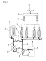
- Fig. 2 is a schematically describes a conventional propulsion device of a liquefied gas carrier propelled by electric power.
- a duel fuel engine 150 is mounted to the propulsion device.
- the duel fuel engine 150 may use any one of MDO (marine diesel oil) and gas fuel such as a natural boiled-off gas and a forced boiled-off gas, as fuel.
- the propulsion device with the duel fuel engine 150 of the liquefied gas carrier propelled by electric power includes: a boiled-off gas compressor 102 for compressing a natural boiled-off gas supplied from a cargo tank 100; a fuel pump 145 for forcing a liquefied gas out of the cargo tank 100; a forcing vaporizer 147 for artificially evaporating the liquefied gas from the cargo tank 100; a main electric power generator 160 for generating electric power by driving the duel fuel engine 150; a motor 170 rotatively driven by the generated electric power; a reducer 180 converting a rotating force of the motor 170 into the proper number of times of rotation and the torque; and a propeller 190 turning by the rotating force of the motor 170 and generating a propulsive force.
- the aforementioned conventional liquefied gas carriers respectively propelled by the steam turbine and electric power can use the gas fuel artificially evaporated or generated during the operation as for the fuel of their respective propulsion systems.
- the propulsion systems in conventional liquefied gas carriers does not need to be operated in full service condition, therefore, the accumulated fuel of gas is wasted by using a dumping device or burnt up by using a gas burner, in order to regulate the pressure inside of the cargo tank.
- the conventional liquefied gas carriers cause many problems, such as energy waste and economical loss thereby.
- FR 2851301 A1 discloses a gaseous fuel supplying equipment for a ship, the equipment comprising a compressor driven by a motor and having an input connected to a tank and an exit connected to a supply collector of an energy production assembly.
- the equipment further comprises a submerged pump at a bottom of the tank, which is connected to an input of an evaporator whose output is connected to the supply collector.
- a buffer tank is connected to the supply collector by a valve, the buffer tank containing gas under a pressure greater than the supply pressure.
- the buffer tank is supplied with gas by a dedicated compressor.
- the valve is intended to gradually discharge gas from the buffer tank into the supply collector to thereby control the pressure in the supply collector in an event of a sudden increase of the load of the energy production assembly.
- the present invention provides a fuel supply apparatus of the liquefied gas carrier and a fuel supply method thereof for temporarily storing remaining gas fuel at high pressure wherein the remaining gas fuel is a naturally evaporated gas in a cargo tank or an additionally supplied gas to be used as fuel, and decompressing the stored gas to be used as fuel of a propulsion system when fuel supply is required.
- a fuel supply apparatus of a liquefied gas carrier as defined in claim 1.
- the gas fuel may be at least one of a natural boiled-off gas naturally evaporated in the cargo tank, a forced boiled-off gas which is artificially evaporated, and a gas additionally supplied for the use of fuel.
- the compressed gas storage tank may be disposed in a space between an engine room of the liquefied gas carrier and the cargo tank.
- the compressor is a multistage high-pressure compressor.
- the compressed gas storage tank may include an explosion-proof film disposed at the outside thereof, to prevent an accident by explosion of the high-pressure gas fuel in an emergency.
- the decompressor is a multistage decompressor.
- the gas fuel may be at least one of a natural boiled-off gas naturally evaporated in the cargo tank, a forced boiled-off gas which is artificially evaporated, and a gas additionally supplied for the use of fuel.
- the remaining boiled-off gas, forced boiled-off gas, or a small quantity of the gas fuel separately supplied for the use of fuel is compressed into a high pressure and stored, and the compressed gas or gas fuel is decompressed to be used as the fuel of the propulsion system when necessary. Therefore, in the present invention, the waste of the boiled-off gas for the regulation of the pressure inside the cargo tank is not required, and the oil fuel (for example, DO, HFO, and the like) to be used as the fuel of the propulsion system is saved, whereby the liquefied gas carrier in accordance with the present invention can be highly competitive.
- the oil fuel for example, DO, HFO, and the like
- Fig. 1 is a schematic view illustrating a conventional propulsion device of a liquefied gas carrier propelled by a steam turbine;
- Fig. 2 is a schematic view describing another conventional propulsion device of a liquefied gas carrier propelled by electric power
- Fig. 3 is a block diagram providing a fuel supply apparatus of a liquefied gas carrier in accordance with an embodiment of the present invention, which is applied to a liquefied gas carrier propelled by a steam turbine;
- Fig. 4 is a block diagram showing the fuel supply apparatus of Fig. 3 , which is applied to a liquefied gas carrier propelled by electric power;
- Fig. 5 is a schematic view partially illustrating a side of the liquefied gas carrier having the fuel supply apparatus of Fig. 3 ;
- Fig. 6 is a schematic view partially showing a plan of the liquefied gas carrier having the fuel supply apparatus of Fig. 3 ;
- Fig. 7 is a flow chart describing a fuel supply method of a liquefied gas carrier in accordance with another embodiment of the present invention.
- Fig. 3 is a block diagram illustrating a fuel supply apparatus of a liquefied gas carrier in accordance with an embodiment of the present invention which is applied to a liquefied gas carrier propelled by a steam turbine.
- Fig. 4 is a block diagram illustrating the fuel supply apparatus of Fig. 3 applied to a liquefied gas carrier propelled by electric power.
- Fig. 5 is a schematic view illustrating a part of a side view of the liquefied gas carrier onto which the fuel supply apparatus of Fig. 3 is mounted
- Fig. 6 is a schematic view illustrating a part of a plan view of the liquefied gas carrier onto which the fuel supply apparatus of Fig. 3 is mounted.
- Fig. 7 is a flow chart describing a fuel supply method of a liquefied gas carrier in accordance with an embodiment of the present invention.
- Fig. 3 shows a fuel supply apparatus of a liquefied gas carrier applied to a liquefied gas carrier driven by a steam turbine.
- the fuel supply apparatus has: a compressor 108 for compressing gas fuel, such as a natural or a forced boiled-off gas, into a high pressure; a compressed gas storage tank 114 for storing the compressed high pressure gas fuel filling the compressed gas storage tank 114; and a decompressor 116 for decompressing the stored high-pressure gas fuel when fuel supply is required.
- gas fuel such as a natural or a forced boiled-off gas
- the gas fuel such as a boiled-off gas compressed into a fuel condition pressure (approximately, 6.5bar) by a boiled-off gas compressor 102 or a artificially evaporated gas generated by a fuel pump 145 and a forcing vaporizer 147, can be used as fuel of a propulsion system (wherein the propulsion system refers to the system related to the generation of a driving force of a ship, i.e., the propulsion system driven by electric power refers to a set including an engine, a generator, a motor, a reducer, a propeller and the like, while the propulsion system propelled by the steam turbine refers to a set including a boiler, a turbine, a propeller, a generator and the like).
- the propulsion system refers to the system related to the generation of a driving force of a ship, i.e., the propulsion system driven by electric power refers to a set including an engine, a generator, a motor, a reducer, a propeller and
- the gas fuel can be used for fuel of the propulsion system by opening a first valve 104 of a pipe connected to the propulsion system and closing a second valve 106 of a pipe connected to the compressor 108, the compressed gas storage tank 114 and the decompressor 116 which are the elements of the embodiment.
- the propulsion system does not require the fuel. Therefore, the first valve 104 is closed to stop the supply of the gas fuel into the propulsion system, and the second valve 106 is opened to introduce the generated gas fuel into the compressor 108.
- the compressor 108 is a device for compressing the introduced gas fuel into a high pressure.
- the compression rate of the compressor 108 may slightly vary according to exemplary embodiments. However, it is preferable to use a multistage compressor for a stable performance with a great compression rate.
- the gas fuel compressed into a high pressure by the compressor 108 fills the compressed gas storage tank 114 and is stored therein by opening a third valve 110 and closing a fourth valve 112.
- the compressed gas storage tank 114 is capable of being filled with the gas fuel compressed into a high pressure and storing the gas fuel.
- the capacity of the compressed gas storage tank 114 may be decided in consideration of taking time for loading and unloading while the liquefied gas carrier is moored or anchored. Therefore, it is preferable that the compressed gas storage tank 114 has the capacity capable of storing all the boiled-off gas generated in the cargo tank 100 while the liquefied gas carrier is moored or anchored.
- a single large tank or a plurality of medium and small tanks connected with each other may be employed as the compressed gas storage tank 114.
- An explosion-proof film 115 may be provided at the outside of the compressed gas storage tank 114.
- the explosion-proof film 115 is a protection film device which can be installed inside or outside of a case of the compressed gas storage tank 114.
- the explosion-proof film 115 may be formed of steel materials, and it protects people or facilities around the compressed gas storage tank 114 from the fragments produced when the compressed gas storage tank 114 explodes.
- the high pressure fuel of gas filling the compressed gas storage tank 114 and stored therein is decompressed into a proper pressure to be used in the propulsion system and can be supplied when fuel supply is required.
- the decompressor 116 decompresses the gas fuel.
- the decompressor 116 is a device for decompressing the high-pressure gas fuel into a pressure proper to be used for the propulsion system, therefore, it is preferable to employ a multistage decompressor for stably performing even if a pressure rate is great.
- a multistage decompression valve of self-control type is employed, so that a droop phenomenon occurring during a normal operation can be reduced, comparing the other valves, and performance can be more stable.
- the multistage decompression valve of self-control type which is not specifically illustrated, may include general elements such as a diaphragm, a seat, a disc, a strainer, a spring and the like.
- the high-pressure gas fuel filling the compressed gas storage tank 114 and stored therein is decompressed by the decompressor 116 so that the gas fuel can be used as fuel of a boiler 120. Further, the boiled-off gas or the forcedly evaporated gas without processing of the compressor 108, the compressed gas storage tank 114 and the decompressor 116 can be also used as the fuel of the boiler 120.
- a turbine 130 By using high-pressure steam generated by operation of the boiler 120, a turbine 130 can be driven to drive a propeller 190, and a regular electric power generator 140 can be operated to generate electric energy to be used for inside the ship.
- Fig. 4 illustrates an embodiment of the fuel supply apparatus described in Fig. 3 , wherein the fuel supply apparatus is applied to a liquefied gas carrier propelled by electric power.
- the liquefied gas carrier propelled by the electric power shown in Fig. 4 uses the fuel supply apparatus having the same elements with the elements of the apparatus used for the liquefied gas carrier driven by the steam turbine shown in Fig. 3 . Therefore, only different operations with that of the apparatus shown in Fig. 3 will be described.
- the liquefied gas carrier propelled by the electric power which has the fuel supply apparatus including the elements aforementioned, stops mooring or anchoring and starts operating, i.e., when fuel supply to the propulsion system is required
- the high-pressure gas fuel filling the compressed gas storage tank 114 and stored therein is decompressed by the decompressor 116, so that the gas fuel can be used for fuel of a duel fuel engine 150.
- the natural boiled-off gas or the forced boiled-off gas without processing of the compressor 108, the compressed gas storage tank 114 and the decompressor 116 can be also used as for fuel of the duel fuel engine 150.
- a main electric power generator 160 is driven to generate electric power.
- the generated electric power generates a proper driving force by using a motor 170 and a reducer 180, to rotate a propeller 190.
- the liquefied gas carrier propelled by the electric power may use MDO (marine diesel oil) or gas fuel for fuel when the empty carrier is operated.
- MDO marine diesel oil
- gas fuel for fuel when the empty carrier is operated.
- Figs. 5 and 6 are schematic views respectively illustrating a side and a plan of the liquefied gas carrier having the fuel supply apparatus in accordance with the embodiment of Fig. 3 .
- the compressed gas storage tank 114 with the explosion-proof film 115 in accordance with the present embodiment is provided in a space between an engine room 200 and the cargo tank 100.
- the engine room 200 refers to the secured space for mounting the propulsion system
- the cargo tank 100 refers to the space for storing the liquefied gas
- the secured space for the compressed gas storage tank 114 is an extra space between the engine room 200 and the cargo tank 100.
- the secured space is preferable to be the extra space which does not disturb shell plating work of the ship and is capable of passing, and arranging pipes and performing maintenance of various kinds of equipment.
- the compressed gas storage tank 114 may be disposed anywhere on the ship.
- Fig. 7 is a flow chart describing a fuel supply method of a liquefied gas carrier in accordance with an embodiment of the present invention.
- the embodiment of the present invention includes a compression step S301 where gas fuel which artificially evaporates or naturally evaporates in the cargo tank, or additionally supplied to be used as fuel is compressed into a high pressure.
- the compressed gas storage tank 114 can also store therein the gas supplied for the use of fuel at a high-pressure. That is, when loading the gas fuel, a small quantity of the fuel of gas in a compressed gas state can be stored in the compressed gas storage tank 114 for the use of fuel, instead of being storing in a liquefied state in the cargo tank.
- the compression step S301 it is possible to compress all of the boiled-off gas, the forcing vaporized gas obtained by artificially evaporating the liquefied gas, and the small quantity of the fuel of gas which has not been stored in the liquefied state upon loading for the use of fuel.
- the multistage high-pressure compressor may be used in this step.
- the compressed high-pressure gas fuel fills the compressed gas storage tank and is stored therein.
- the gas fuel compressed into a high pressure in the compression step S301 is stored in the compressed gas storage tank 114 including the explosion-proof film 115 shown in Fig. 3 .
- a decompression step S305 the high pressure gas fuel stored in the compressed gas storage tank is drawn and decompressed into a pressure to be used in the propulsion system.
- the multistage decompressor such as the multistage decompression valve, may be used for compression of the high-pressure gas fuel.
- the decompressed gas fuel is supplied to be used for fuel of the propulsion system.
- the decompressed gas fuel is used as fuel of the boiler to generate steam.
- the decompressed gas fuel is used as fuel of the duel fuel engine.
- the remaining boiled-off gas, forced boiled-off gas, or a small quantity of the gas fuel separately supplied for the use of fuel is compressed into a high pressure and stored, and the compressed gas or gas fuel is decompressed to be used as the fuel of the propulsion system when necessary. Therefore, in the present invention, the waste of the boiled-off gas for the regulation of the pressure inside the cargo tank is not required, and the oil fuel (for example, DO, HFO, and the like) to be used as the fuel of the propulsion system is saved, whereby the liquefied gas carrier in accordance with the present invention can be highly competitive.
- the oil fuel for example, DO, HFO, and the like
Landscapes
- Engineering & Computer Science (AREA)
- Mechanical Engineering (AREA)
- Chemical & Material Sciences (AREA)
- Combustion & Propulsion (AREA)
- Ocean & Marine Engineering (AREA)
- Physics & Mathematics (AREA)
- Thermal Sciences (AREA)
- General Engineering & Computer Science (AREA)
- Filling Or Discharging Of Gas Storage Vessels (AREA)
Description
- The present invention relates to a fuel supply apparatus of a liquefied gas carrier and a fuel supply method thereof and, more particularly, to a fuel supply apparatus of a liquefied gas carrier and a fuel supply method thereof for compressing a natural gas which is a naturally or artificially evaporated gas in a cargo tank or an additionally supplied gas to be used as fuel into a high pressure and storing the natural gas, and decompressing the stored natural gas to be used as fuel of a propulsion system when necessary.
- Background Art
- In general, LNG (liquefied natural gas) or LPG (liquefied natural gas) is employed as a liquefied gas to be used as fuel. The liquefied gas is generally contained in a cargo tank of a liquefied gas carrier, to be carried.
- During carriage of the liquefied gas, a small quantity of the liquefied gas partially and naturally evaporates in a cargo tank due to an increase of the inside energy of the liquefied gas caused by movement of the liquefied gas and a temperature difference of the liquefied gas from the outside air. Such an evaporated gas is called natural boiled-off gas.
- The natural boiled-off gas can be used as fuel of the liquefied gas carrier when the liquefied gas carrier is operated. However, the natural boiled-off gas is continuously accumulated in the cargo tank when the liquefied gas carrier is moored or anchored, to increase a pressure inside the cargo tank, so that various accidents such as a crack or explosion of the cargo tank occur.
- Generally, the liquefied gas carrier may be largely classified, according to a propulsion mode, into two types: a liquefied gas carrier propelled by a steam turbine, and a liquefied gas carrier propelled by electric power.
-
Fig. 1 schematically illustrates a conventional propulsion device of a liquefied gas carrier propelled by a steam turbine. As shown inFig. 1 , the propulsion device includes: acargo tank 100 for storing therein a liquefied natural gas; a boiled-offgas compressor 102 for compressing gas fuel supplied from thecargo tank 100; agas blocking valve 104 for blocking supply of the gas fuel in an emergency, being connected with the Boiled-offgas compressor 102; aboiler 120 for receiving the gas fuel compressed by the boiled-offgas compressor 102 and generating steam of high temperature and high pressure; aturbine 130 driven by the steam of high temperature and high pressure supplied from theboiler 120; apropeller 190 turning by a driving force from theturbine 130; and a regularelectric power generator 140 driven by using the steam of high temperature and high pressure and generating electric power. In the liquefied gas carrier propelled by the steam turbine, the propulsion device drives theturbine 130 by using the steam of high temperature and high pressure generated in theboiler 120 and generates a propulsive force by turning thepropeller 190. Further, the regularelectric power generator 140 is driven by using the steam of high temperature and high pressure generated in theboiler 120 to generate the regular electric power required for a ship (for example, the power for a living space in the ship). -
Fig. 2 is a schematically describes a conventional propulsion device of a liquefied gas carrier propelled by electric power. InFig. 2 , aduel fuel engine 150 is mounted to the propulsion device. Theduel fuel engine 150 may use any one of MDO (marine diesel oil) and gas fuel such as a natural boiled-off gas and a forced boiled-off gas, as fuel. The propulsion device with theduel fuel engine 150 of the liquefied gas carrier propelled by electric power includes: a boiled-offgas compressor 102 for compressing a natural boiled-off gas supplied from acargo tank 100; afuel pump 145 for forcing a liquefied gas out of thecargo tank 100; a forcingvaporizer 147 for artificially evaporating the liquefied gas from thecargo tank 100; a mainelectric power generator 160 for generating electric power by driving theduel fuel engine 150; amotor 170 rotatively driven by the generated electric power; areducer 180 converting a rotating force of themotor 170 into the proper number of times of rotation and the torque; and apropeller 190 turning by the rotating force of themotor 170 and generating a propulsive force. - The aforementioned conventional liquefied gas carriers respectively propelled by the steam turbine and electric power can use the gas fuel artificially evaporated or generated during the operation as for the fuel of their respective propulsion systems. However, when the liquefied gas carriers are moored or anchored, the propulsion systems in conventional liquefied gas carriers does not need to be operated in full service condition, therefore, the accumulated fuel of gas is wasted by using a dumping device or burnt up by using a gas burner, in order to regulate the pressure inside of the cargo tank.
- As mentioned above, the conventional liquefied gas carriers cause many problems, such as energy waste and economical loss thereby.
- Closest prior art
FR 2851301 A1 - In view of the above, the present invention provides a fuel supply apparatus of the liquefied gas carrier and a fuel supply method thereof for temporarily storing remaining gas fuel at high pressure wherein the remaining gas fuel is a naturally evaporated gas in a cargo tank or an additionally supplied gas to be used as fuel, and decompressing the stored gas to be used as fuel of a propulsion system when fuel supply is required.
- Technical Solution
- In accordance with a first embodiment of the present invention, there is provided a fuel supply apparatus of a liquefied gas carrier as defined in
claim 1. Further embodiments of the - fuel supply apparatus of the present invention are described in the dependent claims.
- The gas fuel may be at least one of a natural boiled-off gas naturally evaporated in the cargo tank, a forced boiled-off gas which is artificially evaporated, and a gas additionally supplied for the use of fuel.
- Further, the compressed gas storage tank may be disposed in a space between an engine room of the liquefied gas carrier and the cargo tank.
- Further, the compressor is a multistage high-pressure compressor.
- Further, the compressed gas storage tank may include an explosion-proof film disposed at the outside thereof, to prevent an accident by explosion of the high-pressure gas fuel in an emergency.
- Further, the decompressor is a multistage decompressor.
- In accordance with a second embodiment of the present invention, there is provided a fuel supply method of a liquefied gas carrier as defined in claim 7. A further embodiment of this method is described in claim 8.
- The gas fuel may be at least one of a natural boiled-off gas naturally evaporated in the cargo tank, a forced boiled-off gas which is artificially evaporated, and a gas additionally supplied for the use of fuel.
- Advantageous Effects
- In accordance with the fuel supply apparatus of a liquefied gas carrier and the fuel supply method thereof, the remaining boiled-off gas, forced boiled-off gas, or a small quantity of the gas fuel separately supplied for the use of fuel is compressed into a high pressure and stored, and the compressed gas or gas fuel is decompressed to be used as the fuel of the propulsion system when necessary. Therefore, in the present invention, the waste of the boiled-off gas for the regulation of the pressure inside the cargo tank is not required, and the oil fuel (for example, DO, HFO, and the like) to be used as the fuel of the propulsion system is saved, whereby the liquefied gas carrier in accordance with the present invention can be highly competitive.
- Furthermore, in accordance with the fuel supply apparatus of a liquefied gas carrier and the fuel supply method thereof, burning out the boiled-off gas for the regulation of the pressure inside the cargo tank is not required, so that the environment problems caused by great amounts of hazardous gas production can be prevented.
- While the invention has been shown and described with respect to the preferred embodiments, it will be understood by those skilled in the art that various changes and modifications may be made without departing from the scope of the invention as defined in the following claims.
- Brief Description of the Drawings
- The objects and features of the present invention will become apparent from the following description of preferred embodiments given in conjunction with the accompanying drawings, in which:
-
Fig. 1 is a schematic view illustrating a conventional propulsion device of a liquefied gas carrier propelled by a steam turbine; -
Fig. 2 is a schematic view describing another conventional propulsion device of a liquefied gas carrier propelled by electric power; -
Fig. 3 is a block diagram providing a fuel supply apparatus of a liquefied gas carrier in accordance with an embodiment of the present invention, which is applied to a liquefied gas carrier propelled by a steam turbine; -
Fig. 4 is a block diagram showing the fuel supply apparatus ofFig. 3 , which is applied to a liquefied gas carrier propelled by electric power; -
Fig. 5 is a schematic view partially illustrating a side of the liquefied gas carrier having the fuel supply apparatus ofFig. 3 ; -
Fig. 6 is a schematic view partially showing a plan of the liquefied gas carrier having the fuel supply apparatus ofFig. 3 ; and -
Fig. 7 is a flow chart describing a fuel supply method of a liquefied gas carrier in accordance with another embodiment of the present invention. - Best Mode for Carrying Out the Invention
- Embodiments of the present invention will now be described with reference to the accompanying drawings for
Figs. 3 to 6 which form a part hereof. -
Fig. 3 is a block diagram illustrating a fuel supply apparatus of a liquefied gas carrier in accordance with an embodiment of the present invention which is applied to a liquefied gas carrier propelled by a steam turbine. Further,Fig. 4 is a block diagram illustrating the fuel supply apparatus ofFig. 3 applied to a liquefied gas carrier propelled by electric power. Further,Fig. 5 is a schematic view illustrating a part of a side view of the liquefied gas carrier onto which the fuel supply apparatus ofFig. 3 is mounted, andFig. 6 is a schematic view illustrating a part of a plan view of the liquefied gas carrier onto which the fuel supply apparatus ofFig. 3 is mounted. Further,Fig. 7 is a flow chart describing a fuel supply method of a liquefied gas carrier in accordance with an embodiment of the present invention. -
Fig. 3 shows a fuel supply apparatus of a liquefied gas carrier applied to a liquefied gas carrier driven by a steam turbine. In this embodiment, the fuel supply apparatus has: acompressor 108 for compressing gas fuel, such as a natural or a forced boiled-off gas, into a high pressure; a compressedgas storage tank 114 for storing the compressed high pressure gas fuel filling the compressedgas storage tank 114; and adecompressor 116 for decompressing the stored high-pressure gas fuel when fuel supply is required. - The gas fuel, such as a boiled-off gas compressed into a fuel condition pressure (approximately, 6.5bar) by a boiled-off
gas compressor 102 or a artificially evaporated gas generated by afuel pump 145 and aforcing vaporizer 147, can be used as fuel of a propulsion system (wherein the propulsion system refers to the system related to the generation of a driving force of a ship, i.e., the propulsion system driven by electric power refers to a set including an engine, a generator, a motor, a reducer, a propeller and the like, while the propulsion system propelled by the steam turbine refers to a set including a boiler, a turbine, a propeller, a generator and the like). - That is, when the liquefied gas carrier is in operation, the propulsion system requires fuel continuously. At this time, the gas fuel can be used for fuel of the propulsion system by opening a
first valve 104 of a pipe connected to the propulsion system and closing asecond valve 106 of a pipe connected to thecompressor 108, the compressedgas storage tank 114 and thedecompressor 116 which are the elements of the embodiment. - However, when the liquefied gas carrier is not operated but moored or anchored, the propulsion system does not require the fuel. Therefore, the
first valve 104 is closed to stop the supply of the gas fuel into the propulsion system, and thesecond valve 106 is opened to introduce the generated gas fuel into thecompressor 108. - The
compressor 108 is a device for compressing the introduced gas fuel into a high pressure. The compression rate of thecompressor 108 may slightly vary according to exemplary embodiments. However, it is preferable to use a multistage compressor for a stable performance with a great compression rate. - The gas fuel compressed into a high pressure by the
compressor 108 fills the compressedgas storage tank 114 and is stored therein by opening athird valve 110 and closing afourth valve 112. - The compressed
gas storage tank 114 is capable of being filled with the gas fuel compressed into a high pressure and storing the gas fuel. The capacity of the compressedgas storage tank 114 may be decided in consideration of taking time for loading and unloading while the liquefied gas carrier is moored or anchored. Therefore, it is preferable that the compressedgas storage tank 114 has the capacity capable of storing all the boiled-off gas generated in thecargo tank 100 while the liquefied gas carrier is moored or anchored. A single large tank or a plurality of medium and small tanks connected with each other may be employed as the compressedgas storage tank 114. - An explosion-
proof film 115 may be provided at the outside of the compressedgas storage tank 114. The explosion-proof film 115 is a protection film device which can be installed inside or outside of a case of the compressedgas storage tank 114. The explosion-proof film 115 may be formed of steel materials, and it protects people or facilities around the compressedgas storage tank 114 from the fragments produced when the compressedgas storage tank 114 explodes. - Further, the high pressure fuel of gas filling the compressed
gas storage tank 114 and stored therein is decompressed into a proper pressure to be used in the propulsion system and can be supplied when fuel supply is required. At this time, thedecompressor 116 decompresses the gas fuel. By closing thethird valve 110 on a pipe connected to thecompressor 108 and opening thefourth valve 112 on a pipe to thedecompressor 116, the high-pressure fuel of gas in the compressedgas storage tank 114 is introduced into thedecompressor 116. - The
decompressor 116 is a device for decompressing the high-pressure gas fuel into a pressure proper to be used for the propulsion system, therefore, it is preferable to employ a multistage decompressor for stably performing even if a pressure rate is great. In this embodiment, a multistage decompression valve of self-control type is employed, so that a droop phenomenon occurring during a normal operation can be reduced, comparing the other valves, and performance can be more stable. The multistage decompression valve of self-control type, which is not specifically illustrated, may include general elements such as a diaphragm, a seat, a disc, a strainer, a spring and the like. - When the liquefied gas carrier driven by the steam turbine, which has the fuel supply apparatus including the elements aforementioned, stops mooring or anchoring to start operating, the high-pressure gas fuel filling the compressed
gas storage tank 114 and stored therein is decompressed by thedecompressor 116 so that the gas fuel can be used as fuel of aboiler 120. Further, the boiled-off gas or the forcedly evaporated gas without processing of thecompressor 108, the compressedgas storage tank 114 and thedecompressor 116 can be also used as the fuel of theboiler 120. - By using high-pressure steam generated by operation of the
boiler 120, aturbine 130 can be driven to drive apropeller 190, and a regularelectric power generator 140 can be operated to generate electric energy to be used for inside the ship. -
Fig. 4 illustrates an embodiment of the fuel supply apparatus described inFig. 3 , wherein the fuel supply apparatus is applied to a liquefied gas carrier propelled by electric power. The liquefied gas carrier propelled by the electric power shown inFig. 4 uses the fuel supply apparatus having the same elements with the elements of the apparatus used for the liquefied gas carrier driven by the steam turbine shown inFig. 3 . Therefore, only different operations with that of the apparatus shown inFig. 3 will be described. - When the liquefied gas carrier propelled by the electric power, which has the fuel supply apparatus including the elements aforementioned, stops mooring or anchoring and starts operating, i.e., when fuel supply to the propulsion system is required, the high-pressure gas fuel filling the compressed
gas storage tank 114 and stored therein is decompressed by thedecompressor 116, so that the gas fuel can be used for fuel of aduel fuel engine 150. Further, the natural boiled-off gas or the forced boiled-off gas without processing of thecompressor 108, the compressedgas storage tank 114 and thedecompressor 116 can be also used as for fuel of theduel fuel engine 150. - By the operation of the
duel fuel engine 150, a mainelectric power generator 160 is driven to generate electric power. The generated electric power generates a proper driving force by using amotor 170 and areducer 180, to rotate apropeller 190. - The liquefied gas carrier propelled by the electric power may use MDO (marine diesel oil) or gas fuel for fuel when the empty carrier is operated.
-
Figs. 5 and6 are schematic views respectively illustrating a side and a plan of the liquefied gas carrier having the fuel supply apparatus in accordance with the embodiment ofFig. 3 . - As shown in
Figs. 5 and6 , the compressedgas storage tank 114 with the explosion-proof film 115 in accordance with the present embodiment is provided in a space between anengine room 200 and thecargo tank 100. Theengine room 200 refers to the secured space for mounting the propulsion system, and thecargo tank 100 refers to the space for storing the liquefied gas, wherein the secured space for the compressedgas storage tank 114 is an extra space between theengine room 200 and thecargo tank 100. The secured space is preferable to be the extra space which does not disturb shell plating work of the ship and is capable of passing, and arranging pipes and performing maintenance of various kinds of equipment. However, the compressedgas storage tank 114 may be disposed anywhere on the ship. -
Fig. 7 is a flow chart describing a fuel supply method of a liquefied gas carrier in accordance with an embodiment of the present invention. - As described in
Fig. 7 , the embodiment of the present invention includes a compression step S301 where gas fuel which artificially evaporates or naturally evaporates in the cargo tank, or additionally supplied to be used as fuel is compressed into a high pressure. - In this embodiment, a remaining natural boiled-off gas or forced boiled=off gas fills the compressed
gas storage tank 114 and is stored therein, so that the liquefied gas carrier can use the stored gas as fuel by decompressing the stored gas when fuel supply is required. Additionally, the compressedgas storage tank 114 can also store therein the gas supplied for the use of fuel at a high-pressure. That is, when loading the gas fuel, a small quantity of the fuel of gas in a compressed gas state can be stored in the compressedgas storage tank 114 for the use of fuel, instead of being storing in a liquefied state in the cargo tank. Therefore, in the compression step S301, it is possible to compress all of the boiled-off gas, the forcing vaporized gas obtained by artificially evaporating the liquefied gas, and the small quantity of the fuel of gas which has not been stored in the liquefied state upon loading for the use of fuel. The multistage high-pressure compressor may be used in this step. - Subsequently, in a filling and storing step S303, the compressed high-pressure gas fuel fills the compressed gas storage tank and is stored therein. The gas fuel compressed into a high pressure in the compression step S301 is stored in the compressed
gas storage tank 114 including the explosion-proof film 115 shown inFig. 3 . - Subsequently, in a decompression step S305, the high pressure gas fuel stored in the compressed gas storage tank is drawn and decompressed into a pressure to be used in the propulsion system. The multistage decompressor, such as the multistage decompression valve, may be used for compression of the high-pressure gas fuel.
- Finally, in a fuel supply step S307, the decompressed gas fuel is supplied to be used for fuel of the propulsion system. When the fuel supply apparatus in accordance with the embodiment of the present invention is applied to the liquefied gas carrier propelled by the steam turbine, the decompressed gas fuel is used as fuel of the boiler to generate steam. When the fuel supply apparatus is applied to the liquefied gas carrier propelled by the electric power, the decompressed gas fuel is used as fuel of the duel fuel engine.
- As described above, in accordance with the fuel supply apparatus of a liquefied gas carrier and the fuel supply method thereof, the remaining boiled-off gas, forced boiled-off gas, or a small quantity of the gas fuel separately supplied for the use of fuel is compressed into a high pressure and stored, and the compressed gas or gas fuel is decompressed to be used as the fuel of the propulsion system when necessary. Therefore, in the present invention, the waste of the boiled-off gas for the regulation of the pressure inside the cargo tank is not required, and the oil fuel (for example, DO, HFO, and the like) to be used as the fuel of the propulsion system is saved, whereby the liquefied gas carrier in accordance with the present invention can be highly competitive.
- Furthermore, in accordance with the fuel supply apparatus of a liquefied gas carrier and the fuel supply method thereof, burning out the boiled-off gas for the regulation of the pressure inside the cargo tank is not required, so that the environment problems caused by great amounts of hazardous gas production can be prevented
- While the invention has been shown and described with respect to the preferred embodiments, it will be understood by those skilled in the art that various changes and modifications may be made without departing from the scope of the invention as defined in the following claims.
Claims (8)
- A fuel supply apparatus of a liquefied gas carrier, comprising:a cargo tank (100);a first pipe extending from the cargo tank (100) for connecting the cargo tank (100) to a propulsion system (120, 130, 190; 150, 160, 170, 180, 190);a first valve (104) located in the first pipe;a second pipe which branches off from the first pipe upstream of the first valve (104) and is connected to a compressor (108);the compressor (108) being adapted to compress gas fuel into a high pressure;a second valve (106) located in the second pipe upstream of the compressor (108);a third pipe extending from the compressor (108) to a compressed gas storage tank (114);the compressed gas storage tank (114) being filled with the compressed high-pressure gas fuel, for storing the gas fuel;a third valve (110) located in the third pipe downstream of the compressor (108);a fourth pipe which branches off from the third pipe downstream of the third valve (110) and is connected to a decompressor (116);the decompressor (116) being adapted to decompress the high-pressure gas fuel drawn from the compressed gas storage tank (114) into a pressure to be used in the propulsion system (120, 130, 190; 150, 160, 170, 180, 190), to supply fuel to the propulsion system (120, 130, 190; 150, 160, 170, 180, 190); anda fourth valve (112) located in the fourth pipe upstream of the decompressor (116); so thatgas fuel can be used for fuel of the propulsion system (120, 130, 190; 150, 160, 170, 180, 190) by opening the first valve (104) and closing the second valve (106), when the liquefied gas carrier is in operation and the propulsion system (120, 130, 190; 150, 160, 170, 180, 190) requires fuel continuously,supply of the gas fuel into the propulsion system (120, 130, 190; 150, 160, 170, 180, 190) can be stopped by closing the first valve (104) and gas fuel can be introduced into the compressor (108) by opening the second valve (106), when the liquefied gas carrier is not operated but moored or anchored and the propulsion system does not require the fuel,the gas fuel compressed into a high pressure by the compressor (108) can be filled into the compressed gas storage tank (114) and stored therein by opening the third valve (110) and closing the fourth valve (112), andhigh-pressure gas fuel in the compressed gas storage tank (114) can be introduced into the decompressor (116) by closing the third valve (110) and opening the fourth valve (112), when fuel supply is required.
- The fuel supply apparatus of claim 1, wherein the gas fuel is at least one of a natural boiled-off gas naturally evaporated in the cargo tank (100), a forced boiled-off gas which is artificially evaporated, and a gas additionally supplied for the use of fuel.
- The fuel supply apparatus of any one of claims 1 and 2, wherein the compressed gas storage tank (114) is disposed in a space between an engine room (200) of the liquefied gas carrier and the cargo tank (100).
- The fuel supply apparatus of any one of claims 1 to 3, wherein the compressor (108) is a multistage high-pressure compressor.
- The fuel supply apparatus of any one of claims 1 to 3, wherein the compressed gas storage tank (114) includes an explosion-proof steel film (115) disposed at the outside thereof, to prevent an accident by explosion of the high-pressure gas fuel in an emergency.
- The fuel supply apparatus of any one of claims 1 to 3, wherein the decompressor (116) is a multistage decompressor.
- A fuel supply method of a liquefied gas carrier, comprising:supplying gas fuel into a propulsion system (120, 130, 190; 150, 160, 170, 180, 190) when the liquefied gas carrier is in operation so that the propulsion system (120, 130, 190; 150, 160, 170, 180, 190) requires fuel continuously;when the liquefied gas carrier is not operated but moored or anchored so that the propulsion system does not require the fuel:when fuel supply is required:stopping the supply of the gas fuel into the propulsion system (120, 130, 190; 150, 160, 170, 180, 190);introducing the generated gas fuel into a compressor (108) ;compressing (S301) the gas fuel into a high pressure; andfilling (S303) a compressed gas storage tank (114) with the compressed high-pressure gas fuel to be stored therein; anddrawing (S305) the stored high-pressure gas fuel and decompressing the gas fuel into a pressure to be used for the propulsion system (120, 130, 190; 150, 160, 170, 180, 190); andsupplying (S307) the decompressed gas fuel to the propulsion system (120, 130, 190; 150, 160, 170, 180, 190) to be used as a fuel.
- The fuel supply method of claim 7, wherein the gas fuel is at least one of a natural boiled-off gas naturally evaporated in a cargo tank (100), a forced boiled-off gas which is artificially evaporated, and a gas additionally supplied for the use of fuel.
Applications Claiming Priority (2)
| Application Number | Priority Date | Filing Date | Title |
|---|---|---|---|
| KR1020060129103A KR100812723B1 (en) | 2006-12-18 | 2006-12-18 | Fuel supply apparatus and method of liquefied gas carrier |
| PCT/KR2007/006639 WO2008075882A1 (en) | 2006-12-18 | 2007-12-18 | Fuel supply apparatus of liquefied gas carrier and fuel supply method thereof |
Publications (3)
| Publication Number | Publication Date |
|---|---|
| EP2102058A1 EP2102058A1 (en) | 2009-09-23 |
| EP2102058A4 EP2102058A4 (en) | 2011-05-11 |
| EP2102058B1 true EP2102058B1 (en) | 2012-09-26 |
Family
ID=39398556
Family Applications (1)
| Application Number | Title | Priority Date | Filing Date |
|---|---|---|---|
| EP07851606A Active EP2102058B1 (en) | 2006-12-18 | 2007-12-18 | Fuel supply apparatus of liquefied gas carrier and fuel supply method thereof |
Country Status (5)
| Country | Link |
|---|---|
| US (1) | US10450045B2 (en) |
| EP (1) | EP2102058B1 (en) |
| JP (1) | JP5070295B2 (en) |
| KR (1) | KR100812723B1 (en) |
| WO (1) | WO2008075882A1 (en) |
Cited By (2)
| Publication number | Priority date | Publication date | Assignee | Title |
|---|---|---|---|---|
| CN102341303B (en) * | 2009-03-03 | 2014-07-09 | Stx造船海洋株式会社 | Boil-off gas treatment apparatus for electric-propelled lng carrier having re-liquefaction function and method thereof |
| CN110475713A (en) * | 2017-04-13 | 2019-11-19 | 三菱造船株式会社 | ship |
Families Citing this family (34)
| Publication number | Priority date | Publication date | Assignee | Title |
|---|---|---|---|---|
| EP2286165A2 (en) * | 2008-05-20 | 2011-02-23 | Shell Internationale Research Maatschappij B.V. | Method of cooling and liquefying a hydrocarbon stream, an apparatus therefor, and a floating structure, caisson or off-shore platform comprising such an apparatus |
| DE102008061192A1 (en) * | 2008-12-09 | 2010-06-17 | Man Diesel Se | Gas supply system for drives of liquefied gas carrier, has gas line system, over which natural gas evaporating in liquefied gas tank of liquefied gas carrier is promoted |
| JP5167158B2 (en) * | 2009-01-29 | 2013-03-21 | 三菱重工業株式会社 | Liquefied fuel carrier and its propulsion system |
| DE102009015411A1 (en) * | 2009-03-27 | 2010-10-07 | Marine-Service Gmbh | Method and device for operating a drive machine for a ship for transporting liquefied gas |
| KR100961867B1 (en) | 2009-10-16 | 2010-06-09 | 대우조선해양 주식회사 | Floating structure with a fuel gas tank |
| KR101210916B1 (en) * | 2009-10-16 | 2012-12-11 | 대우조선해양 주식회사 | Floating structure with a fuel gas tank |
| KR100967818B1 (en) | 2009-10-16 | 2010-07-05 | 대우조선해양 주식회사 | Ship for supplying liquefied fuel gas |
| KR101060887B1 (en) | 2009-11-03 | 2011-08-31 | 현대중공업 주식회사 | Pressure regulation based compressed gas discharge system for compressed gas carrier |
| DE102010007328A1 (en) * | 2010-02-08 | 2011-08-11 | Meyer Werft GmbH, 26871 | Seagoing vessel, in particular gas-powered seagoing vessel |
| KR101239352B1 (en) * | 2010-02-24 | 2013-03-06 | 삼성중공업 주식회사 | Floating liquefied natural gas charging station |
| CA2716283C (en) | 2010-10-01 | 2013-07-30 | Westport Power Inc. | Two engine system with a gaseous fuel stored in liquefied form |
| KR101210921B1 (en) * | 2010-10-29 | 2012-12-11 | 대우조선해양 주식회사 | Boil-off gas handling apparatus and method |
| WO2012118317A2 (en) * | 2011-02-28 | 2012-09-07 | 한국과학기술원 | Lng refueling system and boil-off gas treatment method |
| KR101631176B1 (en) * | 2011-04-05 | 2016-06-17 | 현대중공업 주식회사 | Dual fuel system having supplying fuel in lpg carrier |
| AU2012283998A1 (en) * | 2011-07-19 | 2014-01-23 | Chevron U.S.A. Inc. | Method and system for combusting boil-off gas and generating electricity at an offshore LNG marine terminal |
| JP5688343B2 (en) * | 2011-08-29 | 2015-03-25 | ジャパンマリンユナイテッド株式会社 | Fuel tank support structure and floating structure |
| JP5688348B2 (en) * | 2011-09-06 | 2015-03-25 | ジャパンマリンユナイテッド株式会社 | Fuel tank and floating structure |
| KR101280893B1 (en) * | 2011-11-23 | 2013-07-02 | 삼성중공업 주식회사 | Liquefied Natural Gas Supplying Apparatus |
| KR101324620B1 (en) * | 2011-12-02 | 2013-11-01 | 삼성중공업 주식회사 | Liquid Cargo Tank Having Rotation Unit and Marine Structure having the Same |
| KR101393620B1 (en) * | 2012-06-12 | 2014-05-12 | 한국과학기술연구원 | Underwater moving object using supercavitation |
| KR101435390B1 (en) * | 2012-08-23 | 2014-08-28 | 삼성중공업 주식회사 | Fuel cell systen and ship having the same |
| WO2014080445A1 (en) * | 2012-11-26 | 2014-05-30 | 中国電力株式会社 | Bog processing apparatus and bog processing method |
| KR101413544B1 (en) * | 2013-05-06 | 2014-07-02 | 주식회사래티스테크놀로지 | A Temporary Boil-off Gas Storage System |
| KR102176540B1 (en) * | 2014-01-24 | 2020-11-09 | 대우조선해양 주식회사 | Fuel Tank Module and Fuel Supply System Using The Same for LNG Fuelled Marine Vessel |
| KR20150115120A (en) * | 2014-04-02 | 2015-10-14 | 현대중공업 주식회사 | A Treatment System of Liquefied Gas and method for the same |
| JP5953363B2 (en) * | 2014-12-25 | 2016-07-20 | 三井造船株式会社 | Floating structure with liquefied gas storage facility |
| KR101643086B1 (en) * | 2015-02-17 | 2016-07-26 | 현대중공업 주식회사 | Dual fuel system having supplying fuel in lpg carrier |
| KR20160120373A (en) * | 2015-04-07 | 2016-10-18 | 삼성중공업 주식회사 | Fuel gas supply system |
| JP6038225B2 (en) * | 2015-05-11 | 2016-12-07 | 三菱重工業株式会社 | Gas fired engine |
| EP3362353A4 (en) * | 2015-10-16 | 2019-07-31 | Cryostar SAS | METHOD OF EVAPORATION GAS TREATMENT APPARATUS FOR FEEDING AT LEAST ONE MOTOR |
| CN106184691A (en) * | 2016-09-27 | 2016-12-07 | 上海新奥新能源技术有限公司 | A kind of multi-functional LNG generating ship |
| KR101853943B1 (en) * | 2016-10-07 | 2018-05-02 | 삼성중공업 주식회사 | Generation Facilities Integrated Vessel |
| KR102332936B1 (en) * | 2020-04-03 | 2021-11-30 | 한국조선해양 주식회사 | Fuel Supply System and Ship having the same |
| DE102021101340B4 (en) | 2021-01-22 | 2022-09-15 | Iav Gmbh Ingenieurgesellschaft Auto Und Verkehr | Device and method for emptying at least one gas pressure container for a drive unit that can be operated with gas |
Family Cites Families (29)
| Publication number | Priority date | Publication date | Assignee | Title |
|---|---|---|---|---|
| US2851301A (en) * | 1957-10-09 | 1958-09-09 | Timmons Metal Products Co | Combination pallet rack and truck body |
| DE1147450B (en) * | 1962-03-23 | 1963-04-18 | Arap Armaturen Und App Ges Mit | Multi-stage throttle valve with a valve spindle having throttle channels |
| FR2165729B1 (en) * | 1971-12-27 | 1976-02-13 | Technigaz Fr | |
| NO812328L (en) | 1981-07-08 | 1983-01-10 | Moss Rosenberg Verft As | PROCEDURE FOR THE EXPLOITATION OF DECYCLES FROM THE CRYOGENIC LIQUIDS LIKE FUEL IN A TWO-FUEL DIESEL ENGINE, AND SYSTEM FOR USING THE PROCEDURE |
| DE3245865C2 (en) * | 1982-10-06 | 1984-07-12 | Gebrüder Sulzer AG, Winterthur | Energy supply system for liquid gas tankers |
| JPS62157887A (en) * | 1985-12-28 | 1987-07-13 | Mitsubishi Heavy Ind Ltd | Device for collecting inflammable vaporizing cargo to be utilized in ship |
| JPH0654101B2 (en) | 1987-06-02 | 1994-07-20 | 三菱重工業株式会社 | Gas-fired diesel engine gas supply system |
| US5163409A (en) * | 1992-02-18 | 1992-11-17 | Minnesota Valley Engineering, Inc. | Vehicle mounted LNG delivery system |
| US5411374A (en) * | 1993-03-30 | 1995-05-02 | Process Systems International, Inc. | Cryogenic fluid pump system and method of pumping cryogenic fluid |
| US5540208A (en) * | 1994-09-13 | 1996-07-30 | Nabco Limited | Liquefied gas fuel supply system |
| US5590535A (en) * | 1995-11-13 | 1997-01-07 | Chicago Bridge & Iron Technical Services Company | Process and apparatus for conditioning cryogenic fuel to establish a selected equilibrium pressure |
| US5884488A (en) * | 1997-11-07 | 1999-03-23 | Westport Research Inc. | High pressure fuel supply system for natural gas vehicles |
| US5845479A (en) * | 1998-01-20 | 1998-12-08 | Electric Power Research Institute, Inc. | Method for providing emergency reserve power using storage techniques for electrical systems applications |
| US6153943A (en) * | 1999-03-03 | 2000-11-28 | Mistr, Jr.; Alfred F. | Power conditioning apparatus with energy conversion and storage |
| US6167827B1 (en) * | 1999-05-26 | 2001-01-02 | Guaranteed Advanced Tank Technologies International Ltd. | Maritime chemical tanker having composite tanks for storing and/or transporting liquid organic and inorganic chemicals and the like |
| RU2196238C2 (en) * | 2000-08-16 | 2003-01-10 | ТУЗОВА Алла Павловна | Method of recovery of natural gas expansion energy |
| NO314423B1 (en) * | 2001-07-31 | 2003-03-17 | Hamworthy Kse As | Process of recycling of VOC gas and plant for recycling of VOC gas |
| GB0120661D0 (en) * | 2001-08-24 | 2001-10-17 | Cryostar France Sa | Natural gas supply apparatus |
| JP4048862B2 (en) * | 2002-07-23 | 2008-02-20 | 株式会社Ihi | BOG processing method and apparatus for liquefied gas carrier |
| FR2851301A1 (en) * | 2003-02-19 | 2004-08-20 | Alstom | Gaseous fuel supplying equipment for ship, has accumulator connected to supply collector of energy production assembly by valve and having gas under pressure greater than supply pressure |
| FI118680B (en) | 2003-12-18 | 2008-02-15 | Waertsilae Finland Oy | Gas supply arrangement for a watercraft and method for controlling the pressure of gas in a gas supply system in a watercraft |
| GB0400986D0 (en) * | 2004-01-16 | 2004-02-18 | Cryostar France Sa | Compressor |
| FR2870206B1 (en) | 2004-05-14 | 2006-08-04 | Alstom Sa | INSTALLATION FOR SUPPLYING GASEOUS FUEL TO AN ENERGY PRODUCTION ASSEMBLY OF A LIQUEFIED GAS TRANSPORT VESSEL. |
| CA2580148C (en) * | 2004-09-13 | 2013-12-24 | Argent Marine Operations, Inc. | System and process for transporting lng by non-self-propelled marine lng carrier |
| FR2879261B1 (en) * | 2004-12-10 | 2007-04-13 | Alstom Sa | INSTALLATION FOR THE DELIVERY OF GASEOUS FUEL TO AN ENERGY PRODUCTION ASSEMBLY OF A LIQUEFIED GAS TRANSPORT VESSEL |
| JP4275061B2 (en) * | 2004-12-22 | 2009-06-10 | 三菱重工業株式会社 | Fuel supply apparatus and LNG ship equipped with the same |
| KR200436336Y1 (en) * | 2006-11-30 | 2007-08-01 | 주식회사 동화엔텍 | Pressure Compensation System for Dual Fuel Engine of Gas Carrier |
| US8322357B2 (en) * | 2009-11-13 | 2012-12-04 | Quantum Fuel Systems Technologies Worldwide, Inc. | Integrity protection for pressurized bi-directional systems |
| JP6054101B2 (en) * | 2012-08-29 | 2016-12-27 | 大和ハウス工業株式会社 | Ladder bearing wall |
-
2006
- 2006-12-18 KR KR1020060129103A patent/KR100812723B1/en not_active Expired - Fee Related
-
2007
- 2007-12-18 WO PCT/KR2007/006639 patent/WO2008075882A1/en not_active Ceased
- 2007-12-18 JP JP2009542642A patent/JP5070295B2/en active Active
- 2007-12-18 US US12/519,414 patent/US10450045B2/en active Active
- 2007-12-18 EP EP07851606A patent/EP2102058B1/en active Active
Cited By (3)
| Publication number | Priority date | Publication date | Assignee | Title |
|---|---|---|---|---|
| CN102341303B (en) * | 2009-03-03 | 2014-07-09 | Stx造船海洋株式会社 | Boil-off gas treatment apparatus for electric-propelled lng carrier having re-liquefaction function and method thereof |
| CN110475713A (en) * | 2017-04-13 | 2019-11-19 | 三菱造船株式会社 | ship |
| CN110475713B (en) * | 2017-04-13 | 2021-06-08 | 三菱造船株式会社 | ship |
Also Published As
| Publication number | Publication date |
|---|---|
| EP2102058A1 (en) | 2009-09-23 |
| US10450045B2 (en) | 2019-10-22 |
| US20100089072A1 (en) | 2010-04-15 |
| KR100812723B1 (en) | 2008-03-12 |
| JP5070295B2 (en) | 2012-11-07 |
| WO2008075882A1 (en) | 2008-06-26 |
| JP2010513134A (en) | 2010-04-30 |
| EP2102058A4 (en) | 2011-05-11 |
Similar Documents
| Publication | Publication Date | Title |
|---|---|---|
| US10450045B2 (en) | Fuel supply apparatus of liquefied gas carrier and fuel supply method thereof | |
| KR101895472B1 (en) | Gas Treatment System and Vessel having the same | |
| KR20140138017A (en) | Hybrid fuel supply system and method for a ship engine | |
| KR102884339B1 (en) | Gas purging system for ship | |
| KR102333073B1 (en) | Fuel gas supply system and method for ship | |
| US20250101934A1 (en) | Gas purging system for ship | |
| KR20200091774A (en) | Gas Treatment System, Method of Gas Treatment using the same and Ship having the same | |
| KR20190122942A (en) | BOG treatment system for ship | |
| JP6151207B2 (en) | Reliquefaction equipment for liquefied gas carriers | |
| KR20160091784A (en) | Boil-off gas management system of the lng-fpso and the lng-fpso with the same | |
| KR102011860B1 (en) | System and method for supplying fuel gas for a ship | |
| KR101291246B1 (en) | Ship using bog for dynamic positioning system | |
| KR102827345B1 (en) | Backflow prevention valve set of the gas purging system and gas purging system of ship having same | |
| JP2011178250A (en) | System and method for storing and supplying inert gas | |
| KR102589458B1 (en) | Hybrid generation and propulsion system and method for a vessel | |
| KR20200048942A (en) | A Convertible Vessel | |
| KR102250059B1 (en) | Liquefied Gas Carrier | |
| KR102305887B1 (en) | Gas treatment system and ship having the same | |
| KR102426557B1 (en) | Load Sharing Method Of Ship Including Shaft Generator | |
| KR102137902B1 (en) | Gas treatment system and ship having the same | |
| Skjoldager | Propulsion of LNG Carriers by MAN B&W Two-Stroke Diesel Engines-ME and ME-GI Diesel Engines for LNG Carriers | |
| KR20150028494A (en) | Fuel gas supply system for DFDG and method thereof | |
| KR102011861B1 (en) | System and method for supplying fuel gas for a ship | |
| KR101865056B1 (en) | Apparatus for supplying high pressure natural gas for ship propulsion | |
| KR20180078740A (en) | Gas processing system for vessel with reducer |
Legal Events
| Date | Code | Title | Description |
|---|---|---|---|
| PUAI | Public reference made under article 153(3) epc to a published international application that has entered the european phase |
Free format text: ORIGINAL CODE: 0009012 |
|
| 17P | Request for examination filed |
Effective date: 20090525 |
|
| AK | Designated contracting states |
Kind code of ref document: A1 Designated state(s): AT BE BG CH CY CZ DE DK EE ES FI FR GB GR HU IE IS IT LI LT LU LV MC MT NL PL PT RO SE SI SK TR |
|
| DAX | Request for extension of the european patent (deleted) | ||
| A4 | Supplementary search report drawn up and despatched |
Effective date: 20110413 |
|
| RIC1 | Information provided on ipc code assigned before grant |
Ipc: B63H 21/16 20060101AFI20080715BHEP Ipc: F17C 3/02 20060101ALI20110407BHEP |
|
| REG | Reference to a national code |
Ref country code: DE Ref legal event code: R079 Ref document number: 602007025783 Country of ref document: DE Free format text: PREVIOUS MAIN CLASS: B63H0021160000 Ipc: F17C0003020000 |
|
| RIC1 | Information provided on ipc code assigned before grant |
Ipc: F17C 3/02 20060101AFI20120410BHEP |
|
| GRAP | Despatch of communication of intention to grant a patent |
Free format text: ORIGINAL CODE: EPIDOSNIGR1 |
|
| GRAS | Grant fee paid |
Free format text: ORIGINAL CODE: EPIDOSNIGR3 |
|
| GRAA | (expected) grant |
Free format text: ORIGINAL CODE: 0009210 |
|
| AK | Designated contracting states |
Kind code of ref document: B1 Designated state(s): AT BE BG CH CY CZ DE DK EE ES FI FR GB GR HU IE IS IT LI LT LU LV MC MT NL PL PT RO SE SI SK TR |
|
| REG | Reference to a national code |
Ref country code: GB Ref legal event code: FG4D |
|
| REG | Reference to a national code |
Ref country code: CH Ref legal event code: EP |
|
| REG | Reference to a national code |
Ref country code: AT Ref legal event code: REF Ref document number: 577238 Country of ref document: AT Kind code of ref document: T Effective date: 20121015 |
|
| REG | Reference to a national code |
Ref country code: IE Ref legal event code: FG4D |
|
| REG | Reference to a national code |
Ref country code: DE Ref legal event code: R096 Ref document number: 602007025783 Country of ref document: DE Effective date: 20121122 |
|
| PG25 | Lapsed in a contracting state [announced via postgrant information from national office to epo] |
Ref country code: LT Free format text: LAPSE BECAUSE OF FAILURE TO SUBMIT A TRANSLATION OF THE DESCRIPTION OR TO PAY THE FEE WITHIN THE PRESCRIBED TIME-LIMIT Effective date: 20120926 Ref country code: FI Free format text: LAPSE BECAUSE OF FAILURE TO SUBMIT A TRANSLATION OF THE DESCRIPTION OR TO PAY THE FEE WITHIN THE PRESCRIBED TIME-LIMIT Effective date: 20120926 |
|
| REG | Reference to a national code |
Ref country code: AT Ref legal event code: MK05 Ref document number: 577238 Country of ref document: AT Kind code of ref document: T Effective date: 20120926 |
|
| REG | Reference to a national code |
Ref country code: LT Ref legal event code: MG4D Effective date: 20120926 |
|
| REG | Reference to a national code |
Ref country code: NL Ref legal event code: VDEP Effective date: 20120926 |
|
| PG25 | Lapsed in a contracting state [announced via postgrant information from national office to epo] |
Ref country code: SE Free format text: LAPSE BECAUSE OF FAILURE TO SUBMIT A TRANSLATION OF THE DESCRIPTION OR TO PAY THE FEE WITHIN THE PRESCRIBED TIME-LIMIT Effective date: 20120926 Ref country code: LV Free format text: LAPSE BECAUSE OF FAILURE TO SUBMIT A TRANSLATION OF THE DESCRIPTION OR TO PAY THE FEE WITHIN THE PRESCRIBED TIME-LIMIT Effective date: 20120926 Ref country code: SI Free format text: LAPSE BECAUSE OF FAILURE TO SUBMIT A TRANSLATION OF THE DESCRIPTION OR TO PAY THE FEE WITHIN THE PRESCRIBED TIME-LIMIT Effective date: 20120926 Ref country code: GR Free format text: LAPSE BECAUSE OF FAILURE TO SUBMIT A TRANSLATION OF THE DESCRIPTION OR TO PAY THE FEE WITHIN THE PRESCRIBED TIME-LIMIT Effective date: 20121227 |
|
| PG25 | Lapsed in a contracting state [announced via postgrant information from national office to epo] |
Ref country code: BE Free format text: LAPSE BECAUSE OF FAILURE TO SUBMIT A TRANSLATION OF THE DESCRIPTION OR TO PAY THE FEE WITHIN THE PRESCRIBED TIME-LIMIT Effective date: 20120926 Ref country code: ES Free format text: LAPSE BECAUSE OF FAILURE TO SUBMIT A TRANSLATION OF THE DESCRIPTION OR TO PAY THE FEE WITHIN THE PRESCRIBED TIME-LIMIT Effective date: 20130106 Ref country code: CZ Free format text: LAPSE BECAUSE OF FAILURE TO SUBMIT A TRANSLATION OF THE DESCRIPTION OR TO PAY THE FEE WITHIN THE PRESCRIBED TIME-LIMIT Effective date: 20120926 Ref country code: RO Free format text: LAPSE BECAUSE OF FAILURE TO SUBMIT A TRANSLATION OF THE DESCRIPTION OR TO PAY THE FEE WITHIN THE PRESCRIBED TIME-LIMIT Effective date: 20120926 Ref country code: IS Free format text: LAPSE BECAUSE OF FAILURE TO SUBMIT A TRANSLATION OF THE DESCRIPTION OR TO PAY THE FEE WITHIN THE PRESCRIBED TIME-LIMIT Effective date: 20130126 Ref country code: NL Free format text: LAPSE BECAUSE OF FAILURE TO SUBMIT A TRANSLATION OF THE DESCRIPTION OR TO PAY THE FEE WITHIN THE PRESCRIBED TIME-LIMIT Effective date: 20120926 Ref country code: EE Free format text: LAPSE BECAUSE OF FAILURE TO SUBMIT A TRANSLATION OF THE DESCRIPTION OR TO PAY THE FEE WITHIN THE PRESCRIBED TIME-LIMIT Effective date: 20120926 |
|
| PG25 | Lapsed in a contracting state [announced via postgrant information from national office to epo] |
Ref country code: PL Free format text: LAPSE BECAUSE OF FAILURE TO SUBMIT A TRANSLATION OF THE DESCRIPTION OR TO PAY THE FEE WITHIN THE PRESCRIBED TIME-LIMIT Effective date: 20120926 Ref country code: PT Free format text: LAPSE BECAUSE OF FAILURE TO SUBMIT A TRANSLATION OF THE DESCRIPTION OR TO PAY THE FEE WITHIN THE PRESCRIBED TIME-LIMIT Effective date: 20130128 Ref country code: CY Free format text: LAPSE BECAUSE OF FAILURE TO SUBMIT A TRANSLATION OF THE DESCRIPTION OR TO PAY THE FEE WITHIN THE PRESCRIBED TIME-LIMIT Effective date: 20120926 Ref country code: SK Free format text: LAPSE BECAUSE OF FAILURE TO SUBMIT A TRANSLATION OF THE DESCRIPTION OR TO PAY THE FEE WITHIN THE PRESCRIBED TIME-LIMIT Effective date: 20120926 |
|
| REG | Reference to a national code |
Ref country code: DE Ref legal event code: R097 Ref document number: 602007025783 Country of ref document: DE |
|
| PG25 | Lapsed in a contracting state [announced via postgrant information from national office to epo] |
Ref country code: AT Free format text: LAPSE BECAUSE OF FAILURE TO SUBMIT A TRANSLATION OF THE DESCRIPTION OR TO PAY THE FEE WITHIN THE PRESCRIBED TIME-LIMIT Effective date: 20120926 |
|
| PG25 | Lapsed in a contracting state [announced via postgrant information from national office to epo] |
Ref country code: BG Free format text: LAPSE BECAUSE OF FAILURE TO SUBMIT A TRANSLATION OF THE DESCRIPTION OR TO PAY THE FEE WITHIN THE PRESCRIBED TIME-LIMIT Effective date: 20121226 Ref country code: MC Free format text: LAPSE BECAUSE OF NON-PAYMENT OF DUE FEES Effective date: 20121231 Ref country code: DK Free format text: LAPSE BECAUSE OF FAILURE TO SUBMIT A TRANSLATION OF THE DESCRIPTION OR TO PAY THE FEE WITHIN THE PRESCRIBED TIME-LIMIT Effective date: 20120926 |
|
| REG | Reference to a national code |
Ref country code: CH Ref legal event code: PL |
|
| PLBE | No opposition filed within time limit |
Free format text: ORIGINAL CODE: 0009261 |
|
| STAA | Information on the status of an ep patent application or granted ep patent |
Free format text: STATUS: NO OPPOSITION FILED WITHIN TIME LIMIT |
|
| GBPC | Gb: european patent ceased through non-payment of renewal fee |
Effective date: 20121226 |
|
| PG25 | Lapsed in a contracting state [announced via postgrant information from national office to epo] |
Ref country code: IT Free format text: LAPSE BECAUSE OF FAILURE TO SUBMIT A TRANSLATION OF THE DESCRIPTION OR TO PAY THE FEE WITHIN THE PRESCRIBED TIME-LIMIT Effective date: 20120926 |
|
| 26N | No opposition filed |
Effective date: 20130627 |
|
| REG | Reference to a national code |
Ref country code: IE Ref legal event code: MM4A |
|
| REG | Reference to a national code |
Ref country code: DE Ref legal event code: R119 Ref document number: 602007025783 Country of ref document: DE Effective date: 20130702 |
|
| PG25 | Lapsed in a contracting state [announced via postgrant information from national office to epo] |
Ref country code: CH Free format text: LAPSE BECAUSE OF NON-PAYMENT OF DUE FEES Effective date: 20121231 Ref country code: LI Free format text: LAPSE BECAUSE OF NON-PAYMENT OF DUE FEES Effective date: 20121231 Ref country code: IE Free format text: LAPSE BECAUSE OF NON-PAYMENT OF DUE FEES Effective date: 20121218 Ref country code: DE Free format text: LAPSE BECAUSE OF NON-PAYMENT OF DUE FEES Effective date: 20130702 |
|
| PG25 | Lapsed in a contracting state [announced via postgrant information from national office to epo] |
Ref country code: GB Free format text: LAPSE BECAUSE OF NON-PAYMENT OF DUE FEES Effective date: 20121226 Ref country code: MT Free format text: LAPSE BECAUSE OF FAILURE TO SUBMIT A TRANSLATION OF THE DESCRIPTION OR TO PAY THE FEE WITHIN THE PRESCRIBED TIME-LIMIT Effective date: 20120926 |
|
| PG25 | Lapsed in a contracting state [announced via postgrant information from national office to epo] |
Ref country code: TR Free format text: LAPSE BECAUSE OF FAILURE TO SUBMIT A TRANSLATION OF THE DESCRIPTION OR TO PAY THE FEE WITHIN THE PRESCRIBED TIME-LIMIT Effective date: 20120926 |
|
| PG25 | Lapsed in a contracting state [announced via postgrant information from national office to epo] |
Ref country code: LU Free format text: LAPSE BECAUSE OF NON-PAYMENT OF DUE FEES Effective date: 20121218 |
|
| PG25 | Lapsed in a contracting state [announced via postgrant information from national office to epo] |
Ref country code: HU Free format text: LAPSE BECAUSE OF FAILURE TO SUBMIT A TRANSLATION OF THE DESCRIPTION OR TO PAY THE FEE WITHIN THE PRESCRIBED TIME-LIMIT Effective date: 20071218 |
|
| REG | Reference to a national code |
Ref country code: FR Ref legal event code: PLFP Year of fee payment: 9 |
|
| REG | Reference to a national code |
Ref country code: FR Ref legal event code: PLFP Year of fee payment: 10 |
|
| REG | Reference to a national code |
Ref country code: FR Ref legal event code: PLFP Year of fee payment: 11 |
|
| PGFP | Annual fee paid to national office [announced via postgrant information from national office to epo] |
Ref country code: FR Payment date: 20251008 Year of fee payment: 19 |