EP2101452A1 - Procédés et systèmes pour la récupération de connexions bidirectionnelles - Google Patents
Procédés et systèmes pour la récupération de connexions bidirectionnelles Download PDFInfo
- Publication number
- EP2101452A1 EP2101452A1 EP08300142A EP08300142A EP2101452A1 EP 2101452 A1 EP2101452 A1 EP 2101452A1 EP 08300142 A EP08300142 A EP 08300142A EP 08300142 A EP08300142 A EP 08300142A EP 2101452 A1 EP2101452 A1 EP 2101452A1
- Authority
- EP
- European Patent Office
- Prior art keywords
- switching node
- connection
- unidirectional
- node
- switching
- Prior art date
- Legal status (The legal status is an assumption and is not a legal conclusion. Google has not performed a legal analysis and makes no representation as to the accuracy of the status listed.)
- Withdrawn
Links
Images


Classifications
-
- H—ELECTRICITY
- H04—ELECTRIC COMMUNICATION TECHNIQUE
- H04L—TRANSMISSION OF DIGITAL INFORMATION, e.g. TELEGRAPHIC COMMUNICATION
- H04L45/00—Routing or path finding of packets in data switching networks
- H04L45/02—Topology update or discovery
-
- H—ELECTRICITY
- H04—ELECTRIC COMMUNICATION TECHNIQUE
- H04L—TRANSMISSION OF DIGITAL INFORMATION, e.g. TELEGRAPHIC COMMUNICATION
- H04L43/00—Arrangements for monitoring or testing data switching networks
- H04L43/08—Monitoring or testing based on specific metrics, e.g. QoS, energy consumption or environmental parameters
- H04L43/0805—Monitoring or testing based on specific metrics, e.g. QoS, energy consumption or environmental parameters by checking availability
- H04L43/0811—Monitoring or testing based on specific metrics, e.g. QoS, energy consumption or environmental parameters by checking availability by checking connectivity
-
- H—ELECTRICITY
- H04—ELECTRIC COMMUNICATION TECHNIQUE
- H04L—TRANSMISSION OF DIGITAL INFORMATION, e.g. TELEGRAPHIC COMMUNICATION
- H04L45/00—Routing or path finding of packets in data switching networks
- H04L45/22—Alternate routing
-
- H—ELECTRICITY
- H04—ELECTRIC COMMUNICATION TECHNIQUE
- H04L—TRANSMISSION OF DIGITAL INFORMATION, e.g. TELEGRAPHIC COMMUNICATION
- H04L45/00—Routing or path finding of packets in data switching networks
- H04L45/28—Routing or path finding of packets in data switching networks using route fault recovery
-
- H—ELECTRICITY
- H04—ELECTRIC COMMUNICATION TECHNIQUE
- H04L—TRANSMISSION OF DIGITAL INFORMATION, e.g. TELEGRAPHIC COMMUNICATION
- H04L45/00—Routing or path finding of packets in data switching networks
- H04L45/50—Routing or path finding of packets in data switching networks using label swapping, e.g. multi-protocol label switch [MPLS]
-
- H—ELECTRICITY
- H04—ELECTRIC COMMUNICATION TECHNIQUE
- H04L—TRANSMISSION OF DIGITAL INFORMATION, e.g. TELEGRAPHIC COMMUNICATION
- H04L49/00—Packet switching elements
- H04L49/55—Prevention, detection or correction of errors
- H04L49/557—Error correction, e.g. fault recovery or fault tolerance
Definitions
- the invention relates to the technical field of connection oriented communication networks, especially networks implementing a Multi Protocol Label Switching (MPLS) or Generalized Multi Protocol Label Switching (GMPLS) protocol stack.
- MPLS Multi Protocol Label Switching
- GPLS Generalized Multi Protocol Label Switching
- the Internet Engineering Task Force has initially defined a GMPLS architecture in Request for Comments (RFC) 3945.
- the GMPLS architecture defined in RFC 3945 allows establishment of bi-directional symmetric label-switched paths (LSPs).
- LSPs label-switched paths
- a symmetric bi-directional LSP has the same traffic engineering requirements including fate sharing, protection and restoration, Label-Switching Routers (LSRs), and resource requirements (e.g., latency and jitter) in each direction.
- LSRs Label-Switching Routers
- a bidirectional LSP is an association of two unidirectional data plane connections that could simultaneously deliver traffic in a particular layer between a pair of transport nodes in opposite directions.
- both unidirectional data plane constituents of a bidirectional LSP take identical paths in terms of data links, are provisioned concurrently, and require a single, shared control state.
- bi-directional LSPs both the downstream and upstream data paths, i.e. from initiator to terminator and terminator to initiator, are established using a single set of signaling messages. This reduces the setup latency to essentially one initiator-terminator round trip time plus processing time, and limits the control overhead to the same number of messages as a unidirectional LSP.
- two labels must be allocated. Bidirectional LSP setup is indicated by the presence of an Upstream Label in the appropriate signaling message.
- the GMPLS architecture can be extended to support asymmetric bidirectional LSPs, as described in Internet draft " GMPLS RSVP-TE extension in support of bidirectional LSPs with asymmetric bandwidth requirements", A. Takacs et al., February 2007 .
- RFC 4872 describes protocol-specific procedures and extensions for GMPLS Resource ReSerVation Protocol - Traffic Engineering (RSVP-TE) signaling to support end-to-end LSP recovery, which denotes protection or restoration.
- RSVP-TE Resource ReSerVation Protocol - Traffic Engineering
- a bidirectional working LSP can only be protected or restored through a bidirectional recovery LSP.
- a switching node comprising a data repository storing first connection data relating to a bidirectional connection established between said switching node and a remote switching node along a first path, and second connection data relating to a unidirectional connection provisioned between said switching node and said remote switching node along a second path, and a switch-over module for performing a switch-over action between a first flow direction of the bidirectional connection and the unidirectional connection with the second path.
- an initiator node of the bidirectional connection and/or a terminator node of the bidirectional connection is/are configured in this manner.
- the switching node further comprises a communication module for receiving a recovery triggering signal and for triggering said switch-over module in response to said recovery triggering signal.
- a recovery triggering signal and the corresponding communication module can be implemented in diverse manners. Examples of recovery triggering signals are a notification of a fault affecting the bidirectional connection or a recovery triggering command sent by a recovery deciding entity disposed in the network.
- the switching node can be arranged to enable the switch-over module to be triggered by other means, e.g. by an external command, which may or may not be related to recovery from a fault condition.
- the unidirectional connection is provisioned as a protection connection associated to the bidirectional connection.
- the unidirectional connection is not only provisioned in the control plane, but also fully established in the data plane. Therefore a switch-over action may be performed immediately.
- the unidirectional connection is provisioned as a restoration connection associated to the bidirectional connection, said switching node further comprising a communication module for receiving a recovery triggering signal and a signaling module for sending restoration signaling along the second path to fully establish the unidirectional connection in response to said recovery triggering signal.
- the data repository stores third connection data relating to a unidirectional connection provisioned between said switching node and said remote switching node along a third path, wherein the unidirectional connections along the second and third paths have mutually opposite flow directions, said switching node further comprising a second switch-over module for performing a switch-over action between a second flow direction of the bidirectional connection and the unidirectional connection with the third path.
- the unidirectional connection with the third path can also be provisioned as a protection connection or a restoration connection associated to the bidirectional connection.
- the unidirectional connection with the third path is provisioned as a restoration connection associated to the bidirectional connection, said switching node further comprising a communication module for receiving a recovery triggering signal and a signaling module for sending restoration signaling along the third path to fully establish the unidirectional connection in response to said recovery triggering signal.
- the invention provides also a communication network comprising a first switching node, a second switching node, a first, a second, and a third network paths connecting the first and second switching nodes, I a bidirectional connection established between said first and second switching nodes along the first network path, a first unidirectional connection provisioned between said first and second switching nodes along the second network path, a second unidirectional connection provisioned between said first and second switching nodes along the third network path, wherein the first and second unidirectional connections have opposite flow directions, wherein at least one of the first and second switching nodes comprises a first switch-over module for performing a switch-over action between a first flow direction of the bidirectional connection and the first unidirectional connection, wherein at least one of the first and second switching nodes comprises a second switch-over module for performing a switch-over action between a second flow direction of the bidirectional connection and the second unidirectional connection.
- the invention provides also a method for configuring a switching node in a communication network, comprising the steps of:
- the method further comprises the step of transmitting a signaling message from the second label-switching node to the first label-switching node, in response to receiving said field for requesting unidirectional recovery, to provision said unidirectional connection with the second network path.
- the method further comprises the step of configuring a switch-over module in said second switching node for performing a switch-over action between the flow direction of the bidirectional connection going from the second switching node to the first switching node and said unidirectional connection with the second network path.
- the method further comprises the steps of:
- the method further comprises the step of configuring a switch-over module in said second switching node for performing a switch-over action between the flow direction of the bidirectional connection going from the first switching node to the second switching node and said unidirectional connection with the third network path.
- the invention provides also a digital storage medium having a machine-executable program recorded thereon, and a programmable device comprising a machine-executable program recorded thereon.
- the switching nodes are arranged as label-switching nodes e.g. GMPLS nodes, and the connections are arranged as LSPs.
- Embodiments of the invention are based on the idea of enabling a bidirectional connection to be protected or restored through one or two unidirectional connections.
- only one direction of the bidirectional connection is protected or restored through a unidirectional connection.
- both directions of the bidirectional connection are protected or restored through unidirectional connections that follow different network paths. Since each unidirectional connection requires only bandwidth resources in one direction along the respective network path, the probability of finding an appropriate path with available resources in the network is better than for a bidirectional protecting connection, which would require available resources in both directions along a same path.
- GMPLS Terminology is used in accordance with IETF RFC 4427, unless different definitions are explicitly provided for herein below.
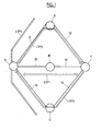
- a GMPLS network comprises a plurality of nodes A, B, C, D, E connected by physical links 10.
- the number of nodes, number of links and topology shown are purely illustrative and not limitative.
- the data plane can be of any type that GMPLS currently supports or will support in the future, e.g. all-optical, WDM, SONET, SDH, Ethernet, IP and others.
- FIG. 1 thick arrows show connections established or provisioned between the nodes.
- a bidirectional LSP referenced as LSP1 is established between nodes A and C along a route A-B-C.
- the LSP LSP1 is a working LSP that is fully established to transport a normal traffic in both directions between at least A and C. Being a bidirectional LSP, the LSP LSP1 has a single, shared control state for both flow directions.
- At least one unidirectional recovery LSP is provisioned or established between nodes A and C along a different route.
- two unidirectional recovery LSPs are shown, referenced as LSP2 and LSP3.
- the LSP LSP2 follows the route C-D-A and has a flow direction from C to A.
- the LSP LSP3 follows the route A-E-C and has a flow direction from A to C.
- each of the unidirectional LSPs LSP2 and LSP3 is intended to recover the traffic of one respective flow direction of the bidirectional LSP LSP1.
- LSPs LSP2 and LSP3 Different recovery types or recovery schemes can be implemented with LSPs LSP2 and LSP3, e.g. dedicated protection, dedicated recovery with or without extra traffic, shared recovery with or without extra traffic, and others.
- the initial provisioning of LSPs LSP2 and LSP3 is done differently. Namely, for protection schemes, LSPs LSP2 and LSP3 are already fully established in the data plane, whereas for restoration schemes, LSPs LSP2 and LSP3 are initially provisioned at least in the control plane and additional signaling takes place to fully establish the pre-provisioned LSP when it must start to carry traffic.
- Different types of restoration schemes can be implemented as well, which involve different levels of pre-provisioning, e.g. pre-computation of route, with or without pre-allocation of resources, with or without pre-selection of resources, with or without cross connection of resources, etc.
- LSP LSP2 as a recovery LSP for a corresponding flow direction of the bidirectional LSP involves at least one switch-over module at the ingress of LSP LSP2 (node C) and/or at the egress (node A).
- a switch-over module is implemented as a switchable bridge function at the ingress, e.g. a broadcast bridge or selector bridge in node C.
- a switch-over module is implemented as a switchable selector function at the egress, e.g. a selective selector in node A.
- the LSP LSP2 is provided with both a switchable bridge function at the ingress, which is arranged to selectively send a normal traffic on the LSP LSP1 or on the LSP LSP2, and a switchable selector function at the egress, which is arranged to selectively receive the normal traffic on the LSP LSP1 or on the LSP LSP2.
- a switch-over module operates by updating a forwarding information base of the corresponding node.
- a normal downstream traffic is carried from node A to node C through LSP LSP1 and a normal upstream traffic is carried from node C to node A through LSP LSP1.
- Extra traffic may or may not be carried by LSPs LSP2 and LSP3, depending on the type of recovery being implemented.
- a fault detection system in the network detects a fault condition affecting the LSP LSP1
- the fault is reported to end nodes A and C, e.g. via an RSVP-TE message NOTIFY or other, which then trigger the recovery of the traffic.
- the components for detecting a fault and making a recovery decision are well-known in the art and can be implemented in any suitable manner in the nodes and or in other devices connected to the network.
- the recovery of the bidirectional traffic can also be triggered through a manual command sent from a network management system (not shown) to the end nodes.
- At least one of node A and node C performs a corresponding switch-over action, i.e. a bridge function in node A and/or a selector function in node C switch/switches from LSP1 to LSP3.
- a switch-over action i.e. a bridge function in node C and/or a selector function in node A switch/switches from LSP1 to LSP2.
- the recovery of a bidirectional LSP by one or two unidirectional LSPs can be applied to many use cases.
- One such use case is when the load of the network does not leave any available path for a bidirectional recovery LSP, as will be illustrated below.
- all links 10 have a bandwidth capacity of 12 units in each direction.
- a unidirectional LSP LSP4 with a bandwidth requirement of 10 units was established from node E to node D.
- the route A-B-C is available to establish the working LSP, though no alternative route remains available for a bidirectional recovery LSP. Yet, the load of the network makes it possible to establish unidirectional recovery LSPs LSP2 and LSP3. Hence, the recovery of the bidirectional LSP by one or more unidirectional LSPs is more flexible, since it is compatible with network states that prevent a bidirectional recovery LSP from being established.
- the respective node controller of nodes A and C includes a connection controller 5 shown on Figure 2 .
- the connection controller 5 includes a signaling module 6, a forwarding information base 8 and a connection state base 9.
- the signaling module 6, e.g. an RSVP-TE module exchanges signaling messages with other nodes through control channels 7, processes signaling messages and updates the data in forwarding information base 8 and connection state base 9 accordingly.
- the forwarding information base 8 stores and maintains forwarding information relating to LSPs that the node is involved in.
- the connection state base 9 stores and maintains parameters and state variables relating to LSPs that the node is involved in, such as bandwidth, status, recovery type, recovery associations and others.
- the forwarding information base 8 is organized as a plurality of linked data structures, which includes a Next Hop Label Forwarding Entry (NHLFE) data structure, an Incoming Label Map (ILM) data structure and a FEC-to-NHLFE map (FTN) data structure.
- NELFE Next Hop Label Forwarding Entry
- ILM Incoming Label Map
- FTN FEC-to-NHLFE map
- the NHLFE data structure 12 includes, for each LSP, an entry containing next-hop information (interface and next-hop address) and label manipulation instructions. It may also include other information required for processing packets in the associated stream.
- Figure 3 shows an entry 21 for LSP1 and an entry 22 for LSP2. In node C, the entry 21 corresponds to the upstream flow direction of the bidirectional LSP.
- the FTN data structure 14 comprises a mapping from the FEC of any incoming packets to corresponding NHLFEs.
- the bidirectional LSP LSP1 has been established to carry a predefined flow in each direction, i.e. a set of IP packets to be treated in the same manner.
- This flow can be identified by a given label or a given Forwarding Equivalence Class (FEC).
- FEC Forwarding Equivalence Class
- the corresponding FEC is defined by a destination IP address mask 134.5/16.
- an entry 23 initially maps that FEC to the entry 21 of the NHLFE data structure 12.
- a switch-over action can be performed by the connection controller by updating the mapping in entry 23 of the FTN data structure 14, so as to link entry 22 of the NHLFE data structure 12 instead of entry 21.
- incoming packets belonging to the FEC will start to be switched along LSP2 instead of LSP1.
- connection controller can perform a switch-over action by updating the mapping in that ILM entry.
- each node processes the RSVP-TE messages that it receives to populate and update a forwarding information base 8 and a connection state base 9 with corresponding connection data.
- different recovery types can be implemented, resulting in different ways of provisioning the recovery resources in the nodes.
- node A is the initiator node of the bidirectional LSP LSP1.
- Node A initiates RSVP-TE signaling to set up the bidirectional LSP LSP1 and the pair of unidirectional recovery LSPs LSP2 and LSP3.
- RSVP-TE RSVP-TE protocol
- the ingress node requests the set-up of an LSP. Therefore, node A can request the set up of LSPs LSP1 and LSP3.
- node A uses a protocol mechanism to inform node C that it must request a unidirectional recovery LSP LSP3 in the reverse direction.
- this mechanism in based on a specific flag or parameter that is put by node A into a connection request message, i.e. a PATH message that serves to set up the bidirectional LSP LSP1.
- a flag can be created in an LSP_ATTRIBUTES object, which is defined in IETF RFC 4420, and can be named "reverse unidirectional protection desired".
- LSP_ATTRIBUTES object which is defined in IETF RFC 4420, and can be named "reverse unidirectional protection desired".
- Other objects and naming conventions may be used as well for the same purpose.
- node A initiates RSVP-TE signaling to set up the bidirectional LSP LSP1.
- a message PATH is sent from node A to node C and a reservation message RESV is sent from node C to node A along the route in the conventional manner.
- node A includes the specific flag or parameter, e.g. a flag "reverse unidirectional protection desired" to cause node C to request a unidirectional recovery LSP in the reverse direction.
- both the downstream and upstream flow directions i.e. from initiator to terminator and terminator to initiator, are established using a single set of signaling messages.
- node C In response to detecting the specific flag in the message PATH, node C searches for a valid unidirectional LSP for the recovery in the reverse direction. Here, it is assumed that such an LSP does not already exist. Therefore node C proceeds to set up one. For that purpose, it is assumed that the route C-D-A has been determined for the unidirectional LSP LSP2.
- a routing module of node C or an external device can perform the route determination.
- node C In order to configure switch-over modules in the end nodes between the LSPs LSP1 and LSP2, node C generates and stores association information in step 35. Node C also communicates this association information to node A, preferably in a corresponding ASSOCIATION object conforming to IETF RFC 4872. In an embodiment, a new ASSOCIATION_TYPE value is used in order to specify that a bidirectional LSP is associated with a unidirectional LSP.
- node C initiates RSVP-TE signaling to set up the unidirectional LSP LSP2.
- a message PATH is sent from node C to node A and a message RESV is sent from node A to node C along the route in the conventional manner.
- node C includes the association information relating to LSPs LSP1 and LSP2.
- this is an ASSOCIATION object, in which the association source is set to the control plane IP address of node C and the association ID is set to the LSP ID of the bidirectional LSP LSP1.
- the LSPs LSP1 and LSP2 can be established in different RSVP sessions or in a same RSVP session.
- node A Being the ingress node, node A is also in charge of requesting the set up of the recovery LSP LSP3 in the forward (downstream) direction. In order to configure switch-over modules in the end nodes between the LSPs LSP1 and LSP3, node A generates and stores association information in step 45. Node A also communicates this association information to node C, preferably in a corresponding ASSOCIATION object conforming to IETF RFC 4872. It is assumed that the route A-E-C has been determined for the unidirectional LSP LSP3. In the step 50, node A initiates RSVP-TE signaling to set up the unidirectional LSP LSP3.
- node A includes the association information relating to LSPs LSP1 and LSP3.
- this is an ASSOCIATION object, in which the association source is set to the control plane IP address of node A and the association ID is set to the LSP ID of the bidirectional LSP LSP1.
- the LSPs LSP1 and LSP3 can be established in different RSVP sessions or in a same RSVP session.
- step 60 the set up of the bidirectional LSP LSP1 is updated by sending a message PATH that includes both association information, i.e. both ASSOCIATION objects, so that node B can also store the recovery related information. However, this step can be omitted to avoid involving node B in the recovery process.
- the end nodes A and C use the association information to configure bridges, selectors and switch-over modules for switching traffic between the working LSP and the recovery LSPs when recovery is decided.
- switch-over modules are configured at one end or at both ends of the recovery LSPs.
- the association information is stored by the end nodes in the connection state base.
- Figure 5 illustrates an example format for the association information thus stored.
- the messages shown on Figure 4 are not exhaustive. The order, in which the messages are sent, is purely illustrative. Some steps can be performed in a different order or simultaneously.
- the bandwidth requirements in the downstream (forward) direction and upstream (reverse) direction can be equal, i.e. symmetric, or unequal, i.e. asymmetric.
- the above embodiment can be modified to omit the set up of one of the unidirectional LSPs. Of course, this would result in the traffic of the bidirectional LSP being protected only in the flow direction for which a recovery LSP was set up.
- the GMPLS architecture can be extended to support point-to-multipoint bidirectional LSPs, as described in French patent application No 0757329 filed on 03 September 2007 .
- the method of protecting bidirectional connections by one or two unidirectional recovery connections can be applied to Point-to-multipoint (P2MP) LSPs as well. Therefore, where reference is made to an LSP in the above embodiments, this reference may be construed as a given branch of a P2MP LSP tree in a P2MP implementation.
- an automatic recovery strategy selection method is executed by a network node or external device to select a recovery strategy adapted to a current load of the network.
- the method comprises the step of searching for an available path for a bidirectional recovery connection. If a path is found, a bidirectional recovery connection is set up. If no such path can be found, a method of recovery by unidirectional connections is selected and one or two unidirectional recovery connections is/are set up.
- a method of recovery by unidirectional connections comprises the steps of searching for an available path for a unidirectional recovery connection in the forward direction, setting up a corresponding unidirectional connection if a path is found, searching for an available path for a unidirectional recovery connection in the reverse direction, and setting up a corresponding unidirectional connection if a path is found.
- the invention may be implemented by means of hardware as well as software.
- the same item of hardware may represent several «modules».
- the functions of the various elements shown in the Figures may be provided through the use of dedicated hardware as well as hardware capable of executing software in association with appropriate software.
- the functions may be provided by a single dedicated processor, by a single shared processor, or by a plurality of individual processors, some of which may be shared.
- processor or “controller” should not be construed to refer exclusively to hardware capable of executing software, and may implicitly include, without limitation, digital signal processor (DSP) hardware, network processor, application specific integrated circuit (ASIC), field programmable gate array (FPGA), read-only memory (ROM) for storing software, random access memory (RAM), and non-volatile storage.
- DSP digital signal processor
- ASIC application specific integrated circuit
- FPGA field programmable gate array
- ROM read-only memory
- RAM random access memory
- non-volatile storage Other hardware, conventional and/or custom, may also be included.
Landscapes
- Engineering & Computer Science (AREA)
- Computer Networks & Wireless Communication (AREA)
- Signal Processing (AREA)
- Environmental & Geological Engineering (AREA)
- Data Exchanges In Wide-Area Networks (AREA)
Priority Applications (1)
| Application Number | Priority Date | Filing Date | Title |
|---|---|---|---|
| EP08300142A EP2101452A1 (fr) | 2008-03-13 | 2008-03-13 | Procédés et systèmes pour la récupération de connexions bidirectionnelles |
Applications Claiming Priority (1)
| Application Number | Priority Date | Filing Date | Title |
|---|---|---|---|
| EP08300142A EP2101452A1 (fr) | 2008-03-13 | 2008-03-13 | Procédés et systèmes pour la récupération de connexions bidirectionnelles |
Publications (1)
| Publication Number | Publication Date |
|---|---|
| EP2101452A1 true EP2101452A1 (fr) | 2009-09-16 |
Family
ID=39661447
Family Applications (1)
| Application Number | Title | Priority Date | Filing Date |
|---|---|---|---|
| EP08300142A Withdrawn EP2101452A1 (fr) | 2008-03-13 | 2008-03-13 | Procédés et systèmes pour la récupération de connexions bidirectionnelles |
Country Status (1)
| Country | Link |
|---|---|
| EP (1) | EP2101452A1 (fr) |
Cited By (5)
| Publication number | Priority date | Publication date | Assignee | Title |
|---|---|---|---|---|
| CN102170391A (zh) * | 2010-02-26 | 2011-08-31 | 中兴通讯股份有限公司 | 关联的双向标签交换路径的创建方法及系统 |
| CN102170392A (zh) * | 2010-02-26 | 2011-08-31 | 中兴通讯股份有限公司 | 关联的双向标签交换路径的创建方法及系统 |
| WO2014035941A1 (fr) * | 2012-08-31 | 2014-03-06 | Cisco Technology, Inc. | Déroutement rapide destiné à des tunnels bidirectionnels à technique de circulation co-acheminée |
| US11190486B2 (en) | 2018-08-13 | 2021-11-30 | Waterfall Security Solutions Ltd. | Automatic security response using one-way links |
| WO2022143468A1 (fr) * | 2020-12-31 | 2022-07-07 | 华为技术有限公司 | Procédé, appareil et système de transmission de données, et support de stockage |
Citations (5)
| Publication number | Priority date | Publication date | Assignee | Title |
|---|---|---|---|---|
| US20020172149A1 (en) * | 2001-05-17 | 2002-11-21 | Hiroshi Kinoshita | Method and apparatus for protection path setup |
| EP1482694A2 (fr) * | 2003-04-28 | 2004-12-01 | Alcatel IP Networks, Inc. | Réseau privé virtuel à tolérance aux défaillances |
| US20050007950A1 (en) * | 2003-07-07 | 2005-01-13 | Liu Hua Autumn | Methods and devices for creating an alternate path for a bi-directional LSP |
| US20050237927A1 (en) * | 2003-05-14 | 2005-10-27 | Shinya Kano | Transmission apparatus |
| EP1679842A1 (fr) * | 2005-01-06 | 2006-07-12 | AT&T Corp. | Gestion de bande passante pour reroutage MPLS rapide |
-
2008
- 2008-03-13 EP EP08300142A patent/EP2101452A1/fr not_active Withdrawn
Patent Citations (5)
| Publication number | Priority date | Publication date | Assignee | Title |
|---|---|---|---|---|
| US20020172149A1 (en) * | 2001-05-17 | 2002-11-21 | Hiroshi Kinoshita | Method and apparatus for protection path setup |
| EP1482694A2 (fr) * | 2003-04-28 | 2004-12-01 | Alcatel IP Networks, Inc. | Réseau privé virtuel à tolérance aux défaillances |
| US20050237927A1 (en) * | 2003-05-14 | 2005-10-27 | Shinya Kano | Transmission apparatus |
| US20050007950A1 (en) * | 2003-07-07 | 2005-01-13 | Liu Hua Autumn | Methods and devices for creating an alternate path for a bi-directional LSP |
| EP1679842A1 (fr) * | 2005-01-06 | 2006-07-12 | AT&T Corp. | Gestion de bande passante pour reroutage MPLS rapide |
Non-Patent Citations (1)
| Title |
|---|
| A. TAKACS, GMPLS RSVP-TE EXTENSION IN SUPPORT OF BIDIRECTIONAL LSPS WITH ASYMMETRIC BANDWIDTH REQUIREMENTS |
Cited By (9)
| Publication number | Priority date | Publication date | Assignee | Title |
|---|---|---|---|---|
| CN102170391A (zh) * | 2010-02-26 | 2011-08-31 | 中兴通讯股份有限公司 | 关联的双向标签交换路径的创建方法及系统 |
| CN102170392A (zh) * | 2010-02-26 | 2011-08-31 | 中兴通讯股份有限公司 | 关联的双向标签交换路径的创建方法及系统 |
| EP2541847A1 (fr) * | 2010-02-26 | 2013-01-02 | ZTE Corporation | Procédé pour l'établissement d'un chemin à commutation d'étiquettes bidirectionnel associé, et système pour sa mise en uvre |
| EP2541847A4 (fr) * | 2010-02-26 | 2014-04-09 | Zte Corp | Procédé pour l'établissement d'un chemin à commutation d'étiquettes bidirectionnel associé, et système pour sa mise en uvre |
| US8824451B2 (en) | 2010-02-26 | 2014-09-02 | Zte Corporation | Method and system for establishing an associated bidirectional label-switched path |
| WO2014035941A1 (fr) * | 2012-08-31 | 2014-03-06 | Cisco Technology, Inc. | Déroutement rapide destiné à des tunnels bidirectionnels à technique de circulation co-acheminée |
| US9160652B2 (en) | 2012-08-31 | 2015-10-13 | Cisco Technology, Inc. | Fast reroute for bidirectional co-routed traffic engineering tunnels |
| US11190486B2 (en) | 2018-08-13 | 2021-11-30 | Waterfall Security Solutions Ltd. | Automatic security response using one-way links |
| WO2022143468A1 (fr) * | 2020-12-31 | 2022-07-07 | 华为技术有限公司 | Procédé, appareil et système de transmission de données, et support de stockage |
Similar Documents
| Publication | Publication Date | Title |
|---|---|---|
| US9088485B2 (en) | System, method and apparatus for signaling and responding to ERO expansion failure in inter-domain TE LSP | |
| EP1820300B1 (fr) | Protection de reacheminement rapide a la peripherie d'un reseau rfc 2547 | |
| EP1867106B1 (fr) | Techniques de prévention de boucles par manipulation par encapsulation de champ ip/mpls | |
| US7586841B2 (en) | System and method for protecting against failure of a TE-LSP tail-end node | |
| US7920466B2 (en) | Protection of hierarchical tunnel head-end nodes | |
| EP2963872B1 (fr) | Anneaux mpls convergents avec découverte automatique | |
| US20120207017A1 (en) | Recovery mechanism for point-to-multipoint traffic | |
| EP2963878B1 (fr) | Protection de trajet pour trajets commutés à étiquette multi-protocole en anneau | |
| EP2963879B1 (fr) | Anneaux de commutation à étiquette multi-protocole | |
| WO2010023511A1 (fr) | Procédés pour établir une connexion de trafic et une connexion de contrôle associée | |
| EP2101452A1 (fr) | Procédés et systèmes pour la récupération de connexions bidirectionnelles | |
| EP2963877B1 (fr) | Contrôle de la bande passante pour des chemins commutés d'étiquettes multi-protocole en boucle | |
| EP2522105A1 (fr) | Technique de rétablissement de chemin partagé | |
| US7702810B1 (en) | Detecting a label-switched path outage using adjacency information | |
| Petersson | MPLS based recovery mechanisms | |
| EP3007393B1 (fr) | Procédé et système pour traiter une signalisation rsvp-te | |
| Abukhshim | Intra-Area, Inter-Area and Inter-AS Traffic Engineering and Path Selection Evaluation | |
| Tsirakakis | Fault Recovery in Carrier Ethernet, Optical and GMPLS Networks |
Legal Events
| Date | Code | Title | Description |
|---|---|---|---|
| PUAI | Public reference made under article 153(3) epc to a published international application that has entered the european phase |
Free format text: ORIGINAL CODE: 0009012 |
|
| AK | Designated contracting states |
Kind code of ref document: A1 Designated state(s): AT BE BG CH CY CZ DE DK EE ES FI FR GB GR HR HU IE IS IT LI LT LU LV MC MT NL NO PL PT RO SE SI SK TR |
|
| AX | Request for extension of the european patent |
Extension state: AL BA MK RS |
|
| 17P | Request for examination filed |
Effective date: 20100316 |
|
| AKX | Designation fees paid |
Designated state(s): AT BE BG CH CY CZ DE DK EE ES FI FR GB GR HR HU IE IS IT LI LT LU LV MC MT NL NO PL PT RO SE SI SK TR |
|
| RAP1 | Party data changed (applicant data changed or rights of an application transferred) |
Owner name: ALCATEL LUCENT |
|
| 111Z | Information provided on other rights and legal means of execution |
Free format text: AT BE BG CH CY CZ DE DK EE ES FI FR GB GR HR HU IE IS IT LI LT LU LV MC MT NL NO PL PT RO SE SI SK TR Effective date: 20130410 |
|
| RAP1 | Party data changed (applicant data changed or rights of an application transferred) |
Owner name: ALCATEL LUCENT |
|
| D11X | Information provided on other rights and legal means of execution (deleted) | ||
| 17Q | First examination report despatched |
Effective date: 20160331 |
|
| STAA | Information on the status of an ep patent application or granted ep patent |
Free format text: STATUS: THE APPLICATION IS DEEMED TO BE WITHDRAWN |
|
| 18D | Application deemed to be withdrawn |
Effective date: 20161011 |