EP2101378A1 - Laser frequency stabilizing device, method and program - Google Patents
Laser frequency stabilizing device, method and program Download PDFInfo
- Publication number
- EP2101378A1 EP2101378A1 EP09154763A EP09154763A EP2101378A1 EP 2101378 A1 EP2101378 A1 EP 2101378A1 EP 09154763 A EP09154763 A EP 09154763A EP 09154763 A EP09154763 A EP 09154763A EP 2101378 A1 EP2101378 A1 EP 2101378A1
- Authority
- EP
- European Patent Office
- Prior art keywords
- light
- longitudinal mode
- laser
- signal
- mode light
- Prior art date
- Legal status (The legal status is an assumption and is not a legal conclusion. Google has not performed a legal analysis and makes no representation as to the accuracy of the status listed.)
- Withdrawn
Links
- 230000000087 stabilizing effect Effects 0.000 title claims abstract description 40
- 238000000034 method Methods 0.000 title claims description 16
- 238000010521 absorption reaction Methods 0.000 claims abstract description 41
- 229920006395 saturated elastomer Polymers 0.000 claims abstract description 23
- 230000010355 oscillation Effects 0.000 claims description 19
- BJQHLKABXJIVAM-UHFFFAOYSA-N bis(2-ethylhexyl) phthalate Chemical compound CCCCC(CC)COC(=O)C1=CC=CC=C1C(=O)OCC(CC)CCCC BJQHLKABXJIVAM-UHFFFAOYSA-N 0.000 claims description 12
- 238000005086 pumping Methods 0.000 claims description 9
- 229910052740 iodine Inorganic materials 0.000 claims description 8
- 239000011630 iodine Substances 0.000 claims description 8
- 230000010287 polarization Effects 0.000 claims description 8
- 239000013078 crystal Substances 0.000 description 12
- 238000005259 measurement Methods 0.000 description 11
- 230000003287 optical effect Effects 0.000 description 11
- PNDPGZBMCMUPRI-UHFFFAOYSA-N iodine Chemical compound II PNDPGZBMCMUPRI-UHFFFAOYSA-N 0.000 description 5
- 229910017502 Nd:YVO4 Inorganic materials 0.000 description 4
- 239000004065 semiconductor Substances 0.000 description 4
- 238000007493 shaping process Methods 0.000 description 4
- 239000007787 solid Substances 0.000 description 3
- 238000010586 diagram Methods 0.000 description 2
- 230000000694 effects Effects 0.000 description 2
- 230000005855 radiation Effects 0.000 description 2
- 238000001228 spectrum Methods 0.000 description 2
- ZCYVEMRRCGMTRW-UHFFFAOYSA-N 7553-56-2 Chemical compound [I] ZCYVEMRRCGMTRW-UHFFFAOYSA-N 0.000 description 1
- 229910009372 YVO4 Inorganic materials 0.000 description 1
- 238000007792 addition Methods 0.000 description 1
- 230000003321 amplification Effects 0.000 description 1
- 238000012986 modification Methods 0.000 description 1
- 230000004048 modification Effects 0.000 description 1
- 238000003199 nucleic acid amplification method Methods 0.000 description 1
- 230000010363 phase shift Effects 0.000 description 1
- 238000004611 spectroscopical analysis Methods 0.000 description 1
Images

Classifications
-
- H—ELECTRICITY
- H01—ELECTRIC ELEMENTS
- H01S—DEVICES USING THE PROCESS OF LIGHT AMPLIFICATION BY STIMULATED EMISSION OF RADIATION [LASER] TO AMPLIFY OR GENERATE LIGHT; DEVICES USING STIMULATED EMISSION OF ELECTROMAGNETIC RADIATION IN WAVE RANGES OTHER THAN OPTICAL
- H01S3/00—Lasers, i.e. devices using stimulated emission of electromagnetic radiation in the infrared, visible or ultraviolet wave range
- H01S3/10—Controlling the intensity, frequency, phase, polarisation or direction of the emitted radiation, e.g. switching, gating, modulating or demodulating
- H01S3/13—Stabilisation of laser output parameters, e.g. frequency or amplitude
- H01S3/139—Stabilisation of laser output parameters, e.g. frequency or amplitude by controlling the mutual position or the reflecting properties of the reflectors of the cavity, e.g. by controlling the cavity length
- H01S3/1392—Stabilisation of laser output parameters, e.g. frequency or amplitude by controlling the mutual position or the reflecting properties of the reflectors of the cavity, e.g. by controlling the cavity length by using a passive reference, e.g. absorption cell
-
- H—ELECTRICITY
- H01—ELECTRIC ELEMENTS
- H01S—DEVICES USING THE PROCESS OF LIGHT AMPLIFICATION BY STIMULATED EMISSION OF RADIATION [LASER] TO AMPLIFY OR GENERATE LIGHT; DEVICES USING STIMULATED EMISSION OF ELECTROMAGNETIC RADIATION IN WAVE RANGES OTHER THAN OPTICAL
- H01S3/00—Lasers, i.e. devices using stimulated emission of electromagnetic radiation in the infrared, visible or ultraviolet wave range
- H01S3/10—Controlling the intensity, frequency, phase, polarisation or direction of the emitted radiation, e.g. switching, gating, modulating or demodulating
- H01S3/13—Stabilisation of laser output parameters, e.g. frequency or amplitude
- H01S3/139—Stabilisation of laser output parameters, e.g. frequency or amplitude by controlling the mutual position or the reflecting properties of the reflectors of the cavity, e.g. by controlling the cavity length
- H01S3/1396—Stabilisation of laser output parameters, e.g. frequency or amplitude by controlling the mutual position or the reflecting properties of the reflectors of the cavity, e.g. by controlling the cavity length by using two modes present, e.g. Zeeman splitting
-
- H—ELECTRICITY
- H01—ELECTRIC ELEMENTS
- H01S—DEVICES USING THE PROCESS OF LIGHT AMPLIFICATION BY STIMULATED EMISSION OF RADIATION [LASER] TO AMPLIFY OR GENERATE LIGHT; DEVICES USING STIMULATED EMISSION OF ELECTROMAGNETIC RADIATION IN WAVE RANGES OTHER THAN OPTICAL
- H01S3/00—Lasers, i.e. devices using stimulated emission of electromagnetic radiation in the infrared, visible or ultraviolet wave range
- H01S3/05—Construction or shape of optical resonators; Accommodation of active medium therein; Shape of active medium
- H01S3/08—Construction or shape of optical resonators or components thereof
- H01S3/08004—Construction or shape of optical resonators or components thereof incorporating a dispersive element, e.g. a prism for wavelength selection
-
- H—ELECTRICITY
- H01—ELECTRIC ELEMENTS
- H01S—DEVICES USING THE PROCESS OF LIGHT AMPLIFICATION BY STIMULATED EMISSION OF RADIATION [LASER] TO AMPLIFY OR GENERATE LIGHT; DEVICES USING STIMULATED EMISSION OF ELECTROMAGNETIC RADIATION IN WAVE RANGES OTHER THAN OPTICAL
- H01S3/00—Lasers, i.e. devices using stimulated emission of electromagnetic radiation in the infrared, visible or ultraviolet wave range
- H01S3/09—Processes or apparatus for excitation, e.g. pumping
- H01S3/091—Processes or apparatus for excitation, e.g. pumping using optical pumping
- H01S3/094—Processes or apparatus for excitation, e.g. pumping using optical pumping by coherent light
- H01S3/0941—Processes or apparatus for excitation, e.g. pumping using optical pumping by coherent light of a laser diode
- H01S3/09415—Processes or apparatus for excitation, e.g. pumping using optical pumping by coherent light of a laser diode the pumping beam being parallel to the lasing mode of the pumped medium, e.g. end-pumping
-
- H—ELECTRICITY
- H01—ELECTRIC ELEMENTS
- H01S—DEVICES USING THE PROCESS OF LIGHT AMPLIFICATION BY STIMULATED EMISSION OF RADIATION [LASER] TO AMPLIFY OR GENERATE LIGHT; DEVICES USING STIMULATED EMISSION OF ELECTROMAGNETIC RADIATION IN WAVE RANGES OTHER THAN OPTICAL
- H01S3/00—Lasers, i.e. devices using stimulated emission of electromagnetic radiation in the infrared, visible or ultraviolet wave range
- H01S3/10—Controlling the intensity, frequency, phase, polarisation or direction of the emitted radiation, e.g. switching, gating, modulating or demodulating
- H01S3/106—Controlling the intensity, frequency, phase, polarisation or direction of the emitted radiation, e.g. switching, gating, modulating or demodulating by controlling devices placed within the cavity
- H01S3/108—Controlling the intensity, frequency, phase, polarisation or direction of the emitted radiation, e.g. switching, gating, modulating or demodulating by controlling devices placed within the cavity using non-linear optical devices, e.g. exhibiting Brillouin or Raman scattering
- H01S3/109—Frequency multiplication, e.g. harmonic generation
-
- H—ELECTRICITY
- H01—ELECTRIC ELEMENTS
- H01S—DEVICES USING THE PROCESS OF LIGHT AMPLIFICATION BY STIMULATED EMISSION OF RADIATION [LASER] TO AMPLIFY OR GENERATE LIGHT; DEVICES USING STIMULATED EMISSION OF ELECTROMAGNETIC RADIATION IN WAVE RANGES OTHER THAN OPTICAL
- H01S3/00—Lasers, i.e. devices using stimulated emission of electromagnetic radiation in the infrared, visible or ultraviolet wave range
- H01S3/10—Controlling the intensity, frequency, phase, polarisation or direction of the emitted radiation, e.g. switching, gating, modulating or demodulating
- H01S3/13—Stabilisation of laser output parameters, e.g. frequency or amplitude
- H01S3/136—Stabilisation of laser output parameters, e.g. frequency or amplitude by controlling devices placed within the cavity
- H01S3/137—Stabilisation of laser output parameters, e.g. frequency or amplitude by controlling devices placed within the cavity for stabilising of frequency
-
- H—ELECTRICITY
- H01—ELECTRIC ELEMENTS
- H01S—DEVICES USING THE PROCESS OF LIGHT AMPLIFICATION BY STIMULATED EMISSION OF RADIATION [LASER] TO AMPLIFY OR GENERATE LIGHT; DEVICES USING STIMULATED EMISSION OF ELECTROMAGNETIC RADIATION IN WAVE RANGES OTHER THAN OPTICAL
- H01S3/00—Lasers, i.e. devices using stimulated emission of electromagnetic radiation in the infrared, visible or ultraviolet wave range
- H01S3/10—Controlling the intensity, frequency, phase, polarisation or direction of the emitted radiation, e.g. switching, gating, modulating or demodulating
- H01S3/13—Stabilisation of laser output parameters, e.g. frequency or amplitude
- H01S3/139—Stabilisation of laser output parameters, e.g. frequency or amplitude by controlling the mutual position or the reflecting properties of the reflectors of the cavity, e.g. by controlling the cavity length
- H01S3/1398—Stabilisation of laser output parameters, e.g. frequency or amplitude by controlling the mutual position or the reflecting properties of the reflectors of the cavity, e.g. by controlling the cavity length by using a supplementary modulation of the output
-
- H—ELECTRICITY
- H01—ELECTRIC ELEMENTS
- H01S—DEVICES USING THE PROCESS OF LIGHT AMPLIFICATION BY STIMULATED EMISSION OF RADIATION [LASER] TO AMPLIFY OR GENERATE LIGHT; DEVICES USING STIMULATED EMISSION OF ELECTROMAGNETIC RADIATION IN WAVE RANGES OTHER THAN OPTICAL
- H01S3/00—Lasers, i.e. devices using stimulated emission of electromagnetic radiation in the infrared, visible or ultraviolet wave range
- H01S3/14—Lasers, i.e. devices using stimulated emission of electromagnetic radiation in the infrared, visible or ultraviolet wave range characterised by the material used as the active medium
- H01S3/16—Solid materials
- H01S3/1601—Solid materials characterised by an active (lasing) ion
- H01S3/1603—Solid materials characterised by an active (lasing) ion rare earth
- H01S3/1611—Solid materials characterised by an active (lasing) ion rare earth neodymium
-
- H—ELECTRICITY
- H01—ELECTRIC ELEMENTS
- H01S—DEVICES USING THE PROCESS OF LIGHT AMPLIFICATION BY STIMULATED EMISSION OF RADIATION [LASER] TO AMPLIFY OR GENERATE LIGHT; DEVICES USING STIMULATED EMISSION OF ELECTROMAGNETIC RADIATION IN WAVE RANGES OTHER THAN OPTICAL
- H01S3/00—Lasers, i.e. devices using stimulated emission of electromagnetic radiation in the infrared, visible or ultraviolet wave range
- H01S3/14—Lasers, i.e. devices using stimulated emission of electromagnetic radiation in the infrared, visible or ultraviolet wave range characterised by the material used as the active medium
- H01S3/16—Solid materials
- H01S3/163—Solid materials characterised by a crystal matrix
- H01S3/1671—Solid materials characterised by a crystal matrix vanadate, niobate, tantalate
- H01S3/1673—YVO4 [YVO]
Definitions
- the present invention relates to a laser frequency stabilizing device, laser frequency stabilizing method and laser frequency stabilizing program for changing the resonant cavity length based on a light output signal to stabilize the oscillation frequency of a laser light.
- a continuous-wave oscillation, 532-nm range solid laser uses a Nd:YAG crystal or the like as a gain medium, which is pumped with a semiconductor laser.
- the wavelength of such the solid laser is utilized as the standard for lengths.
- An actual measurement using a wavelength of the laser light requires oscillations of the laser at a single frequency, that is, in a single longitudinal mode.
- the use of the laser light wavelength for length measurement requires higher frequency stability of the laser light in order to reduce uncertainty of the length measurement.
- the oscillation frequency can be controlled at the center of a saturated absorption signal to produce a laser light with high frequency stability (see, for example, Patent Document 1: JP 2001-274495A ).
- the device in Patent Document 1 modulates the resonant cavity length and controls the oscillation frequency of the laser light to capture the saturated absorption signal. Therefore, modulation takes place in the oscillation frequency of the laser light for use in length measurement and so forth.
- the influence of the modulation associated with the measurement of the saturated absorption signal may deteriorate the measurement accuracy and so forth as a problem.
- the present invention has an object to provide a laser frequency stabilizing device, laser frequency stabilizing method and laser frequency stabilizing program capable of eliminating the influence of modulation at lower costs.
- the present invention provides a laser frequency stabilizing device capable of establishing resonance of a pumping light in a resonant cavity to produce and emit a laser light, applying the laser light to an absorption cell to generate a light output signal, and varying the resonant cavity length based on a saturated absorption signal contained in the light output signal to stabilize the oscillation frequency of the laser light, the device comprising: a laser light producer operative to produce a laser light containing a first longitudinal mode light and a second longitudinal mode light having different wavelengths; a spectrometer operative to spectrally decompose the laser light emitted from the laser light producer into the first longitudinal mode light and the second longitudinal mode light; a first detector operative to detect the light output signal from the absorption cell; a second detector operative to detect the signal intensity of the first longitudinal mode light; a third detector operative to detect the signal intensity of the second longitudinal mode light; an actuator operative to change the resonant cavity length; a first drive controller operative to detect the saturated absorption signal from
- the laser frequency stabilizing device can stabilize the frequency without modulating the resonant cavity length.
- the laser light producer may be configured to produce and emit a first longitudinal mode light and a second longitudinal mode light having adjacent peak wavelengths and mutually orthogonal planes of polarization.
- the switcher may be configured to switch the control by the first drive controller to the control by the second drive controller for control of the actuator when the saturated absorption signal detected at the first detector meets the oscillation frequency of the laser light.
- the first drive controller may be configured to control the actuator on the basis of at least one of a second order differential signal derived from the light output signal and a third order differential signal derived from the light output signal.
- the present invention provides a laser frequency stabilizing method capable of establishing resonance of a pumping light in a resonant cavity to produce a laser light, applying the laser light to an absorption cell to generate a light output signal, and varying the resonant cavity length based on a saturated absorption signal contained in the light output signal to stabilize the oscillation frequency of the laser light, the method comprising: controlling the resonant cavity length based on the light output signal from the absorption cell; and detecting a first longitudinal mode light and a second longitudinal mode light contained in the laser light and having different wavelengths to control the resonant cavity length such that the signal intensity based on the first longitudinal mode light and the signal intensity based on the second longitudinal mode light have a ratio of a certain value.
- the present invention provides a laser frequency stabilizing program capable of establishing resonance of a pumping light in a resonant cavity to produce a laser light, applying the laser light to an absorption cell to generate a light output signal, and varying the resonant cavity length based on a saturated absorption signal contained in the light output signal to stabilize the oscillation frequency of the laser light, the program comprising computer-executable steps of: controlling the resonant cavity length based on the light output signal from the absorption cell; and detecting a first longitudinal mode light and a second longitudinal mode light contained in the laser light and having different wavelengths to control the resonant cavity length such that the signal intensity based on the first longitudinal mode light and the signal intensity based on the second longitudinal mode light have a ratio of a certain value.
- a laser frequency stabilizing device according to an embodiment of the present invention will now be described with reference to the drawings.
- Fig. 1 is a brief block diagram of the laser frequency stabilizing device according to the embodiment of the present invention.
- the laser frequency stabilizing device comprises a laser light producer 10, a laser light spectrometer 20, a first controller 30, a second controller 40, and a switcher 50.
- the laser light producer 10 has a function of producing a laser light.
- the laser light spectrometer 20 has a function of spectrally decomposing the laser light produced at the laser light producer 10.
- the first controller 30 and the second controller 40 have a function of detecting the laser light and controlling the oscillation frequency of the laser light.
- the switcher 50 has a function of switching between the control by the first controller 30 and the control by the second controller 40 for frequency control of the laser light.
- the laser light producer 10 includes a pumping semiconductor laser 11, a beam shaping system 12, and a cabinet 13.
- the pumping semiconductor laser 11 is supplied with a certain current to emit a light L(0) having a wavelength of 808 nm.
- the beam shaping system 12 includes plural optical members. The beam shaping system 12 guides the light L(0) therethrough from the pumping semiconductor laser 11 to the cabinet 13.
- a Nd:YV04 crystal 14a, a KTP crystal 14b, a wavelength plate 15, an etalon 16, a reflecting mirror 17, and an actuator 18 are sequentially arranged on the optical path of the light L(0).
- the Nd: YVO4 crystal 14a is a crystal for diode-laser-pumped solid laser.
- the Nd:YVO4 crystal 14a emits a 1064-nm wavelength light L' (0) by stimulated radiation on application of the light L(0) to excite Nd atoms.
- the Nd:YVO4 crystal 14a is coated to reflect the light L' (0) toward the aide of the beam shaping system 12.
- the KTP crystal 14b is a non-linear optical crystal.
- the KTP crystal 14b converts part of the light L' (0) by stimulated radiation into a secondary harmonic or a 532-nm light.
- the wavelength plate 15 phase-shifts the axis of the vertical polarization of the light L'(0) to change the polarization of the light L'(0).
- the etalon 16 includes high-reflection filters arranged face to face.
- the etalon 16 has a frequency filer function and is previously adjusted to produce two lights (a first and a second longitudinal mode light) having different frequencies (wavelengths), more specifically, a first and a second longitudinal mode light having adjacent peak wavelengths.
- the reflecting mirror 17 is coated to reflect the light L'(0) therefrom and transmit the 532-nm wavelength light therethrough. Therefore, the Nd:YVO4 crystal 14a and the reflecting mirror 17 configure a resonant cavity only for the light L'(0).
- the actuator 18 includes a piezoelectric element.
- the actuator 18 is provided between the cabinet 13 and the reflecting mirror 17.
- the actuator 18 deforms (expands and contracts) in response to the voltage applied thereto. In a word, with the deformation, the actuator 18 shifts the reflecting mirror 17 relative to the Nd:YVO4 crystal 14a to change the resonant cavity length.
- the laser light producer 10 with the adjusted etalon 16 produces a first longitudinal mode light L(1) and a second longitudinal mode light L(2) having adjacent peak locations in the wavelength direction.
- the laser light producer 10 applies the first longitudinal mode light L(1) and the second longitudinal mode light L(2) to the laser light spectrometer 20.
- the direction of the polarization of the first longitudinal mode light L (1) is orthogonal to the direction of the polarization of the second longitudinal mode light L(2).
- the first longitudinal mode light L(1) is a n-light and the second longitudinal mode light L(2) is a ⁇ -light.
- the first longitudinal mode light L(1) is a ⁇ -light and the second longitudinal mode light L(2) is a ⁇ -light, for example.
- the laser light spectrometer 20 includes a beam splitter 201, a polarizing plate 202, a 1/2-wavelength plate 203, a first polarizing beam splitter 204, a prism 205, a 1/2-wavelength plate 206, a second polarizing beam splitter 207, a 1/4-wavelength plate 208, an iodine cell 209, a reflecting mirror 210, and a third polarizing beam splitter 211.
- the beam splitter 201 is provided at a position into which the first longitudinal mode light L(1) and the second longitudinal mode light L(2) from the laser light producer 10 enter.
- the beam splitter 201 splits the first longitudinal mode light L(1) and the second longitudinal mode light L(2).
- the beam splitter 201 transmits part of the first longitudinal mode light L(1) therethrough as a first longitudinal mode light L (1A) and reflects the remainder therefromas a first longitudinal mode light L(1B).
- the beam splitter 201 transmits part of the second longitudinal mode light L(2) therethrough as a second longitudinal mode light L(2A) and reflects the remainder therefrom as a second longitudinal mode light L(2B).
- the polarizing plate 202, the 1/2-wavelength plate 203 and the first polarizing beam splitter 204 are sequentially arranged on the optical path of the first longitudinal mode light L(1A) and the second longitudinal mode light L(2A).
- the polarizing plate 202 is configured to transmit only the first longitudinal mode light L(1A) therethrough and block the second longitudinal mode light L(2A).
- the 1/2-wavelength plate 203 changes the polarization direction of the first longitudinal mode light L(1A) that is a linear polarized light.
- the first polarizing beam splitter 204 splits the first polarized longitudinal mode light L(1A).
- the first polarizing beam splitter 204 transmits part of the first polarized longitudinal mode light L(1A) therethrough to produce a first longitudinal mode light L(1Aa) and reflects the remainder therefrom to produce a first longitudinal mode light L(1Ab).
- the first longitudinal mode light L(1Aa) transmitted through the first polarizing beam splitter 204 is available in length measurement and so forth.
- the prism 205 is provided at a position to which the first longitudinal mode light L(1Ab) reflected at the first polarizing beam splitter 204 is applied.
- the prism 205 receives the first longitudinal mode light L(1Ab) from the first polarizing beam splitter 204 and reflects it therefrom at a certain angle.
- the 1/2-wavelength plate 206, the second polarizing beam splitter 207, the 1/4-wavelength plate 208, the iodine cell 209, and the reflecting mirror 210 are sequentially arranged on the optical path of the first longitudinal mode light L(1Ab) reflected at the prism 205.
- the first longitudinal mode light L(1Ab) is applied, through the 1/2-wavelength plate 206, the secondpolarizing beam splitter 207, thel/4-wavelengthplate 208 and the iodine cell 209, to the reflecting mirror 210. Subsequently, the first longitudinal mode light L(1Ab) travels through the iodine cell 209 and the 1/4-wavelength plate 208 and is reflected at the second polarizing beam splitter 207. On the above optical path, the first longitudinal mode light L(1Ab) transmits through the iodine cell 209, which absorbs light within a specific frequency range to yield an absorption light L(1Ab)',
- the third polarizing beam splitter 211 is arranged on the optical path of the first longitudinal mode light L(1B) and the second longitudinal mode light L(2B).
- the third polarizing beam splitter 211 spectrally decomposes the first longitudinal mode light L(1B) and the second longitudinal mode light L(2B).
- the third polarizing beam splitter 211 reflects the first longitudinal mode light L(1B) therefrom and transmits the second longitudinal mode light L(2B) therethrough.
- the first controller 30 includes a first detector 31, a second order differential lock-in amp 32, a third order differential lock-in amp 33, a main controller 34, a modulation/demodulation signal generator 35, and a first drive controller 36.
- the first detector 31 detects the absorption light L(1Ab)' incoming from the second polarizing beam splitter 207.
- the first detector 31 produces a light output signal Sg1 based on the detected absorption light L(1Ab)'.
- the first detector 31 provides the light output signal Sg1 to the second order differential lock-in amp 32 and the third order differential lock-in amp 33.
- the second order differential lock-in amp 32 demodulates the input of the light output signal Sg1 with a 2f-Hz frequency to produce a second order differential signal Sg2.
- the second order differential lock-in amp 32 provides the produced second order differential signal Sg2 to the main controller 34.
- the third order differential lock-in amp 33 demodulates the input of the light output signal Sg1 with a 3f-Hz frequency to produce a third order differential signal Sg3.
- the third order differential lock-in amp 33 provides the produced third order differential signal Sg3 to the main controller 34.
- the main controller 34 may comprise a PC (Personal Computer).
- the main controller 34 includes a storage unit to store various programs.
- the main controller 34 controls the frequency of the laser light in accordance with the stored various programs.
- the main controller 34 controls the state of the switcher 50 based on the input of the second order differential signal Sg2 and the third order differential signal Sg3.
- the main controller 34 produces a first actuator control signal Sc1 based on the input of the third order differential signal Sg3.
- the first actuator control signal Sc1 is fed to the first drive controller 36 to control the first drive controller 36.
- the modulation/demodulation signal generator 35 provides a 1f-Hz frequency signal to the first drive controller 36.
- the modulation/demodulation signal generator 35 provides a signal having a 2f-Hz frequency to the second order differential lock-in amp 32.
- the modulation/demodulation signal generator 35 provides a 3f-Hz frequency signal to the third order differential lock-in amp 33.
- the first drive controller 36 produces a first control voltage C1 based on the first actuator control signal Sc1 and the 1f-Hz frequency signal and applies the first control voltage C1 to the switcher 50.
- the first control voltage C1 is a voltage modulated with the 1f-Hz frequency.
- the first drive controller 36 controls the actuator 18 based on the third order differential signal Sg3 derived from the light output signal Sg1.
- the second controller 40 includes a second detector 41, a third detector 42, a differential amp 43, and a second drive controller 44.
- the second detector 41 detects the first longitudinal mode light L(1B) incoming from the third polarizing beam splitter 211.
- the second detector 41 produces a first mode signal Sga based on the first detected longitudinal mode light L(1B).
- the second detector 41 provides the first mode signal Sga to the differential amp 43.
- the third detector 42 detects the second longitudinal mode light L(2B) incoming from the third polarizing beam splitter 211.
- the third detector 42 produces a second mode signal Sgb based on the second detected longitudinal mode light L(2B).
- the third detector 42 provides the second mode signal Sgb to the differential amp 43.
- the differential amp 43 leads the first mode signal Sga and the second mode signal Sgb to differential amplification to produce a second actuator control signal Sc2.
- the second actuator control signal Sc2 is a signal for control of the second drive controller 44.
- the second actuator control signal Sc2 is a signal indicative of a ratio between the signal intensity of the first mode signal Sga and the signal intensity of the second mode signal Sgb.
- the differential amp 43 provides the second actuator control signal Sc2 to the second drive controller 44.
- the second drive controller 44 produces a second control voltage C2 based on the second actuator control signal Sc2 and applies the second control voltage C2 to the switcher 50.
- the second control voltage C2 is a voltage based on the ratio between the signal intensity of the first mode signal Sga and the signal intensity of the second mode signal Sgb.
- the switcher 50 has a first through a third terminal 51-53.
- the first terminal 51 is connected to the actuator 18.
- the second terminal 52 is supplied with the first control voltage C1.
- the third terminal 53 is supplied with the second control voltage C2.
- the switcher 50 when the switcher 50 connects the first terminal 51 with the second terminal 52, the actuator 18 is placed under the drive control with the first control voltage C1.
- the switcher 50 connects the first terminal 51 with the third terminal 53, the actuator 18 is placed under the drive control with the second control voltage C2.
- the switcher 50 switches between the connections associated with the first through third terminals 51-53 under the control of the main controller 34.
- the adjustment of the etalon 16 may be executed as follows. First, an optical spectrum analyzer is installed between the beam splitter 201 and the third polarizing beam splitter 211. In addition, a wavelength meter is installed behind the first polarizing beam splitter 204.
- the installed optical spectrum analyzer is used to read two adjacent longitudinal mode lights L(1B), L(2B), then adjust the rotational angle of the etalon 16 in the resonant cavity such that these longitudinal mode lights L(1B), L(2B) can be emitted, and thereafter adjust the first longitudinal mode light L (1A) to have a desired frequency based on a measurement result from a wavelength meter.
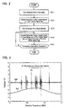
- Fig. 2 is a flowchart illustrative of the laser frequency stabilizing control according to the present embodiment.
- Fig. 3 shows the light output signal Sg1 and the third order differential signal Sg3.
- the main controller 34 first turns the switcher 50 to a first state (step S11).
- the first state is herein defined as a state in which the first terminal 51 is connected with the second terminal 52.
- the main controller 34 sets it such that the first drive controller 36 controls the actuator 18.
- the first drive controller 36 controls driving the actuator 18 based on the light output signal Sg1 (step S12).
- the first drive controller 36 controls the resonant cavity length based on the light output signal Sg1.
- the first drive controller 36 first drives the actuator 18 to measure the third order differential signal Sg3 within a certain frequency region. With this measurement, as shown in Fig. 3 , plural saturated absorption signals P1-Pn (n is a natural number) having peaks and valleys can be observed in the third order differential signal Sg3 within a certain frequency region.
- the first drive controller 36 then drives the actuator 18 to set the oscillation frequency of the third order differential signal Sg3 to meet the central frequency of an arbitrary saturated absorption signal Pk.
- the first longitudinal mode light L(1Aa) for use in length measurement has an oscillation frequency coincident with the central frequency of the set saturated absorption signal Pk.
- the first control voltage C1 output from the first drive controller 36 is modulated with the 1f-Hz frequency signal. Therefore, the first longitudinal mode light L(1Aa) becomes a modulated light.
- the main controller 34 turns the switcher 50 to a second state (step S13).
- the second state is herein defined as a state in which the first terminal 51 is connected with the third terminal 53.
- the main controller 34 sets it such that the second drive controller 44 controls the actuator 18.
- the second drive controller 44 controls driving the actuator 18 based on the signal intensity of the first mode signal Sga and the signal intensity of the second mode signal Sgb (step S14).
- the second drive controller 44 controls the resonant cavity length based on the signal intensity of the first mode signal Sga and the signal intensity of the second mode signal Sgb.
- the second drive controller 44 controls it such that the signal intensity of the first mode signal Sga and the signal intensity of the second mode signal Sgb become equal or both have a constant ratio (of a certain value).
- the main controller 34 decides whether a termination instruction for terminating the control is accepted (step S15) . If the main controller 34 decides that the termination instruction is accepted (step S15, Y), it terminates the control. On the other hand, if the main controller 34 decides that the termination instruction is not accepted (step S15, N), it executes the process at the step S14 repeatedly.
- the laser frequency stabilizing device measures saturated absorption signals while the first drive controller 36 modulates the resonant cavity length and controls the actuator 18 such that the oscillation frequency of the third order differential signal Sg3 meets the central frequency of an arbitrary saturated absorption signal. Subsequently, the laser frequency stabilizing device controls the actuator 18 using the second drive controller 44 based on the signal intensity of the first mode signal Sga and the signal intensity of the second mode signal Sgb. Thus, the laser frequency stabilizing device according to the present embodiment finally stabilizes the laser frequency without modulating the resonant cavity length.
- the laser frequency stabilizing device can produce a stabilized laser light not modulated. Accordingly, the use of the laser light makes it possible to achieve high-precision length measurement. In addition, the laser frequency stabilizing device according to the present embodiment requires no expensive optical element and therefore can be produced at a lower cost.
- the first drive controller 36 drives the actuator 18 in response to the first actuator control signal Sc1 from the main controller 34 based on the third order differential signal Sg3.
- the first drive controller 36 is though not limited to the above configuration and may be configured to drive the actuator 18 in response to a control signal from the main controller 34 based on the second order differential signal Sg2.
- the first drive controller 36 may be configured to control it based on the light output signal Sg1.
- the above embodiment is configured to use the etalon 16 to produce the first longitudinal mode light L (1) and the second longitudinal mode light L(2) though it is not limited to the above configuration.
- a laser tube may be used, which can adjust the resonant cavity length so as to produce the first longitudinal mode light L(1) and the second longitudinal mode light L(2).
- the laser tube may be equipped with a heater around the outer circumference thereof and may be configured stretchable under the temperature control for the heater.
Landscapes
- Physics & Mathematics (AREA)
- Electromagnetism (AREA)
- Engineering & Computer Science (AREA)
- Plasma & Fusion (AREA)
- Optics & Photonics (AREA)
- Lasers (AREA)
Abstract
Description
- The present invention relates to a laser frequency stabilizing device, laser frequency stabilizing method and laser frequency stabilizing program for changing the resonant cavity length based on a light output signal to stabilize the oscillation frequency of a laser light.
- A continuous-wave oscillation, 532-nm range solid laser uses a Nd:YAG crystal or the like as a gain medium, which is pumped with a semiconductor laser. The wavelength of such the solid laser is utilized as the standard for lengths. An actual measurement using a wavelength of the laser light requires oscillations of the laser at a single frequency, that is, in a single longitudinal mode.
- Further, the use of the laser light wavelength for length measurement requires higher frequency stability of the laser light in order to reduce uncertainty of the length measurement. In an iodine-stabilized laser using an iodine molecular absorption line spectrometry, the oscillation frequency can be controlled at the center of a saturated absorption signal to produce a laser light with high frequency stability (see, for example, Patent Document 1:
JP 2001-274495A - The device in
Patent Document 1, however, modulates the resonant cavity length and controls the oscillation frequency of the laser light to capture the saturated absorption signal. Therefore, modulation takes place in the oscillation frequency of the laser light for use in length measurement and so forth. In a word, in the prior art, the influence of the modulation associated with the measurement of the saturated absorption signal may deteriorate the measurement accuracy and so forth as a problem. - To overcome the above problem, there has been proposed a configuration in the art, which includes a modulator such as an electro-optic modulator (EOM). The configuration uses an expensive optical element, which elevates the cost.
- Therefore, the present invention has an object to provide a laser frequency stabilizing device, laser frequency stabilizing method and laser frequency stabilizing program capable of eliminating the influence of modulation at lower costs.
- The present invention provides a laser frequency stabilizing device capable of establishing resonance of a pumping light in a resonant cavity to produce and emit a laser light, applying the laser light to an absorption cell to generate a light output signal, and varying the resonant cavity length based on a saturated absorption signal contained in the light output signal to stabilize the oscillation frequency of the laser light, the device comprising: a laser light producer operative to produce a laser light containing a first longitudinal mode light and a second longitudinal mode light having different wavelengths; a spectrometer operative to spectrally decompose the laser light emitted from the laser light producer into the first longitudinal mode light and the second longitudinal mode light; a first detector operative to detect the light output signal from the absorption cell; a second detector operative to detect the signal intensity of the first longitudinal mode light; a third detector operative to detect the signal intensity of the second longitudinal mode light; an actuator operative to change the resonant cavity length; a first drive controller operative to detect the saturated absorption signal from the light output signal detected at the first detector and control driving the actuator based on the saturated absorption signal; a second drive controller operative to control driving the actuator such that the signal intensity of the first longitudinal mode light detected at the second detector and the signal intensity of the second longitudinal mode light detected at the third detector have a ratio of a certain value; and a switcher operative to switch the control of the actuator between the control by the first drive controller and the control by the second drive controller.
- With such the configuration, the laser frequency stabilizing device can stabilize the frequency without modulating the resonant cavity length.
- Preferably, the laser light producer may be configured to produce and emit a first longitudinal mode light and a second longitudinal mode light having adjacent peak wavelengths and mutually orthogonal planes of polarization. Preferably, the switcher may be configured to switch the control by the first drive controller to the control by the second drive controller for control of the actuator when the saturated absorption signal detected at the first detector meets the oscillation frequency of the laser light. Preferably, the first drive controller may be configured to control the actuator on the basis of at least one of a second order differential signal derived from the light output signal and a third order differential signal derived from the light output signal.
- The present invention provides a laser frequency stabilizing method capable of establishing resonance of a pumping light in a resonant cavity to produce a laser light, applying the laser light to an absorption cell to generate a light output signal, and varying the resonant cavity length based on a saturated absorption signal contained in the light output signal to stabilize the oscillation frequency of the laser light, the method comprising: controlling the resonant cavity length based on the light output signal from the absorption cell; and detecting a first longitudinal mode light and a second longitudinal mode light contained in the laser light and having different wavelengths to control the resonant cavity length such that the signal intensity based on the first longitudinal mode light and the signal intensity based on the second longitudinal mode light have a ratio of a certain value.
- The present invention provides a laser frequency stabilizing program capable of establishing resonance of a pumping light in a resonant cavity to produce a laser light, applying the laser light to an absorption cell to generate a light output signal, and varying the resonant cavity length based on a saturated absorption signal contained in the light output signal to stabilize the oscillation frequency of the laser light, the program comprising computer-executable steps of: controlling the resonant cavity length based on the light output signal from the absorption cell; and detecting a first longitudinal mode light and a second longitudinal mode light contained in the laser light and having different wavelengths to control the resonant cavity length such that the signal intensity based on the first longitudinal mode light and the signal intensity based on the second longitudinal mode light have a ratio of a certain value.
-
-
Fig. 1 is a brief block diagram of a laser frequency stabilizing device according to an embodiment of the present invention. -
Fig. 2 is a flowchart showing laser frequency stabilizing control in the laser frequency stabilizing device according to the embodiment of the present invention. -
Fig. 3 shows a light output signal Sg1 and a third order differential signal Sg3 detected during control in the laser frequency stabilizing device according to the embodiment of the present invention. - A laser frequency stabilizing device according to an embodiment of the present invention will now be described with reference to the drawings.
- A configuration of the laser frequency stabilizing device according to the embodiment of the present invention is described.
Fig. 1 is a brief block diagram of the laser frequency stabilizing device according to the embodiment of the present invention. As shown inFig. 1 , the laser frequency stabilizing device comprises alaser light producer 10, alaser light spectrometer 20, afirst controller 30, asecond controller 40, and aswitcher 50. Thelaser light producer 10 has a function of producing a laser light. Thelaser light spectrometer 20 has a function of spectrally decomposing the laser light produced at thelaser light producer 10. Thefirst controller 30 and thesecond controller 40 have a function of detecting the laser light and controlling the oscillation frequency of the laser light. Theswitcher 50 has a function of switching between the control by thefirst controller 30 and the control by thesecond controller 40 for frequency control of the laser light. - The
laser light producer 10 includes apumping semiconductor laser 11, abeam shaping system 12, and acabinet 13. The pumpingsemiconductor laser 11 is supplied with a certain current to emit a light L(0) having a wavelength of 808 nm. Thebeam shaping system 12 includes plural optical members. Thebeam shaping system 12 guides the light L(0) therethrough from the pumpingsemiconductor laser 11 to thecabinet 13. - Inside the
cabinet 13, a Nd:YV04 crystal 14a, aKTP crystal 14b, awavelength plate 15, anetalon 16, a reflectingmirror 17, and anactuator 18 are sequentially arranged on the optical path of the light L(0). - The Nd: YVO4 crystal 14a is a crystal for diode-laser-pumped solid laser. The Nd:
YVO4 crystal 14a emits a 1064-nm wavelength light L' (0) by stimulated radiation on application of the light L(0) to excite Nd atoms. The Nd:YVO4 crystal 14a is coated to reflect the light L' (0) toward the aide of thebeam shaping system 12. - The
KTP crystal 14b is a non-linear optical crystal. TheKTP crystal 14b converts part of the light L' (0) by stimulated radiation into a secondary harmonic or a 532-nm light. - The
wavelength plate 15 phase-shifts the axis of the vertical polarization of the light L'(0) to change the polarization of the light L'(0). - The
etalon 16 includes high-reflection filters arranged face to face. Theetalon 16 has a frequency filer function and is previously adjusted to produce two lights (a first and a second longitudinal mode light) having different frequencies (wavelengths), more specifically, a first and a second longitudinal mode light having adjacent peak wavelengths. - The reflecting
mirror 17 is coated to reflect the light L'(0) therefrom and transmit the 532-nm wavelength light therethrough. Therefore, the Nd:YVO4 crystal 14a and the reflectingmirror 17 configure a resonant cavity only for the light L'(0). - The
actuator 18 includes a piezoelectric element. Theactuator 18 is provided between thecabinet 13 and the reflectingmirror 17. Theactuator 18 deforms (expands and contracts) in response to the voltage applied thereto. In a word, with the deformation, theactuator 18 shifts the reflectingmirror 17 relative to the Nd:YVO4 crystal 14a to change the resonant cavity length. - The
laser light producer 10 with the adjustedetalon 16 produces a first longitudinal mode light L(1) and a second longitudinal mode light L(2) having adjacent peak locations in the wavelength direction. Thelaser light producer 10 applies the first longitudinal mode light L(1) and the second longitudinal mode light L(2) to thelaser light spectrometer 20. - The direction of the polarization of the first longitudinal mode light L (1) is orthogonal to the direction of the polarization of the second longitudinal mode light L(2). For example, the first longitudinal mode light L(1) is a n-light and the second longitudinal mode light L(2) is a σ-light. Alternatively, the first longitudinal mode light L(1) is a σ-light and the second longitudinal mode light L(2) is a π-light, for example.
- The
laser light spectrometer 20 includes abeam splitter 201, a polarizingplate 202, a 1/2-wavelength plate 203, a first polarizingbeam splitter 204, aprism 205, a 1/2-wavelength plate 206, a second polarizingbeam splitter 207, a 1/4-wavelength plate 208, aniodine cell 209, a reflectingmirror 210, and a third polarizingbeam splitter 211. - The
beam splitter 201 is provided at a position into which the first longitudinal mode light L(1) and the second longitudinal mode light L(2) from thelaser light producer 10 enter. Thebeam splitter 201 splits the first longitudinal mode light L(1) and the second longitudinal mode light L(2). Thebeam splitter 201 transmits part of the first longitudinal mode light L(1) therethrough as a first longitudinal mode light L (1A) and reflects the remainder therefromas a first longitudinal mode light L(1B). Thebeam splitter 201 transmits part of the second longitudinal mode light L(2) therethrough as a second longitudinal mode light L(2A) and reflects the remainder therefrom as a second longitudinal mode light L(2B). - The
polarizing plate 202, the 1/2-wavelength plate 203 and the firstpolarizing beam splitter 204 are sequentially arranged on the optical path of the first longitudinal mode light L(1A) and the second longitudinal mode light L(2A). Thepolarizing plate 202 is configured to transmit only the first longitudinal mode light L(1A) therethrough and block the second longitudinal mode light L(2A). The 1/2-wavelength plate 203 changes the polarization direction of the first longitudinal mode light L(1A) that is a linear polarized light. The firstpolarizing beam splitter 204 splits the first polarized longitudinal mode light L(1A). The firstpolarizing beam splitter 204 transmits part of the first polarized longitudinal mode light L(1A) therethrough to produce a first longitudinal mode light L(1Aa) and reflects the remainder therefrom to produce a first longitudinal mode light L(1Ab). The first longitudinal mode light L(1Aa) transmitted through the firstpolarizing beam splitter 204 is available in length measurement and so forth. - The
prism 205 is provided at a position to which the first longitudinal mode light L(1Ab) reflected at the firstpolarizing beam splitter 204 is applied. Theprism 205 receives the first longitudinal mode light L(1Ab) from the firstpolarizing beam splitter 204 and reflects it therefrom at a certain angle. - The 1/2-
wavelength plate 206, the secondpolarizing beam splitter 207, the 1/4-wavelength plate 208, theiodine cell 209, and the reflectingmirror 210 are sequentially arranged on the optical path of the first longitudinal mode light L(1Ab) reflected at theprism 205. - With the above configuration, the first longitudinal mode light L(1Ab) is applied, through the 1/2-
wavelength plate 206, thesecondpolarizing beam splitter 207, thel/4-wavelengthplate 208 and theiodine cell 209, to the reflectingmirror 210. Subsequently, the first longitudinal mode light L(1Ab) travels through theiodine cell 209 and the 1/4-wavelength plate 208 and is reflected at the secondpolarizing beam splitter 207. On the above optical path, the first longitudinal mode light L(1Ab) transmits through theiodine cell 209, which absorbs light within a specific frequency range to yield an absorption light L(1Ab)', - The third
polarizing beam splitter 211 is arranged on the optical path of the first longitudinal mode light L(1B) and the second longitudinal mode light L(2B). The thirdpolarizing beam splitter 211 spectrally decomposes the first longitudinal mode light L(1B) and the second longitudinal mode light L(2B). The thirdpolarizing beam splitter 211 reflects the first longitudinal mode light L(1B) therefrom and transmits the second longitudinal mode light L(2B) therethrough. - The
first controller 30 includes afirst detector 31, a second order differential lock-inamp 32, a third order differential lock-inamp 33, amain controller 34, a modulation/demodulation signal generator 35, and afirst drive controller 36. - The
first detector 31 detects the absorption light L(1Ab)' incoming from the secondpolarizing beam splitter 207. Thefirst detector 31 produces a light output signal Sg1 based on the detected absorption light L(1Ab)'. Thefirst detector 31 provides the light output signal Sg1 to the second order differential lock-inamp 32 and the third order differential lock-inamp 33. - The second order differential lock-in
amp 32 demodulates the input of the light output signal Sg1 with a 2f-Hz frequency to produce a second order differential signal Sg2. The second order differential lock-inamp 32 provides the produced second order differential signal Sg2 to themain controller 34. - The third order differential lock-in
amp 33 demodulates the input of the light output signal Sg1 with a 3f-Hz frequency to produce a third order differential signal Sg3. The third order differential lock-inamp 33 provides the produced third order differential signal Sg3 to themain controller 34. - The
main controller 34 may comprise a PC (Personal Computer). Themain controller 34 includes a storage unit to store various programs. Themain controller 34 controls the frequency of the laser light in accordance with the stored various programs. Themain controller 34 controls the state of theswitcher 50 based on the input of the second order differential signal Sg2 and the third order differential signal Sg3. Themain controller 34 produces a first actuator control signal Sc1 based on the input of the third order differential signal Sg3. The first actuator control signal Sc1 is fed to thefirst drive controller 36 to control thefirst drive controller 36. - The modulation/
demodulation signal generator 35 provides a 1f-Hz frequency signal to thefirst drive controller 36. The modulation/demodulation signal generator 35 provides a signal having a 2f-Hz frequency to the second order differential lock-inamp 32. The modulation/demodulation signal generator 35 provides a 3f-Hz frequency signal to the third order differential lock-inamp 33. - The
first drive controller 36 produces a first control voltage C1 based on the first actuator control signal Sc1 and the 1f-Hz frequency signal and applies the first control voltage C1 to theswitcher 50. The first control voltage C1 is a voltage modulated with the 1f-Hz frequency. In other word, in the above configuration, thefirst drive controller 36 controls theactuator 18 based on the third order differential signal Sg3 derived from the light output signal Sg1. - The
second controller 40 includes asecond detector 41, athird detector 42, adifferential amp 43, and asecond drive controller 44. - The
second detector 41 detects the first longitudinal mode light L(1B) incoming from the thirdpolarizing beam splitter 211. Thesecond detector 41 produces a first mode signal Sga based on the first detected longitudinal mode light L(1B). Thesecond detector 41 provides the first mode signal Sga to thedifferential amp 43. - The
third detector 42 detects the second longitudinal mode light L(2B) incoming from the thirdpolarizing beam splitter 211. Thethird detector 42 produces a second mode signal Sgb based on the second detected longitudinal mode light L(2B). Thethird detector 42 provides the second mode signal Sgb to thedifferential amp 43. - The
differential amp 43 leads the first mode signal Sga and the second mode signal Sgb to differential amplification to produce a second actuator control signal Sc2. The second actuator control signal Sc2 is a signal for control of thesecond drive controller 44. The second actuator control signal Sc2 is a signal indicative of a ratio between the signal intensity of the first mode signal Sga and the signal intensity of the second mode signal Sgb. Thedifferential amp 43 provides the second actuator control signal Sc2 to thesecond drive controller 44. - The
second drive controller 44 produces a second control voltage C2 based on the second actuator control signal Sc2 and applies the second control voltage C2 to theswitcher 50. The second control voltage C2 is a voltage based on the ratio between the signal intensity of the first mode signal Sga and the signal intensity of the second mode signal Sgb. - The
switcher 50 has a first through a third terminal 51-53. Thefirst terminal 51 is connected to theactuator 18. Thesecond terminal 52 is supplied with the first control voltage C1. Thethird terminal 53 is supplied with the second control voltage C2. - In a word, when the
switcher 50 connects thefirst terminal 51 with thesecond terminal 52, theactuator 18 is placed under the drive control with the first control voltage C1. When theswitcher 50 connects thefirst terminal 51 with thethird terminal 53, theactuator 18 is placed under the drive control with the second control voltage C2. Theswitcher 50 switches between the connections associated with the first through third terminals 51-53 under the control of themain controller 34. (Adjustment ofEtalon 16 according to Present Embodiment) - The following description is given to a method for adjusting the
etalon 16 to emit two adjacent longitudinal mode lights L(1B), L(2B) from the above-describedlaser light producer 10. The adjustment of theetalon 16 may be executed as follows. First, an optical spectrum analyzer is installed between thebeam splitter 201 and the thirdpolarizing beam splitter 211. In addition, a wavelength meter is installed behind the firstpolarizing beam splitter 204. The installed optical spectrum analyzer is used to read two adjacent longitudinal mode lights L(1B), L(2B), then adjust the rotational angle of theetalon 16 in the resonant cavity such that these longitudinal mode lights L(1B), L(2B) can be emitted, and thereafter adjust the first longitudinal mode light L (1A) to have a desired frequency based on a measurement result from a wavelength meter. - The following description is given to the control for stabilizing the laser frequency (laser frequency stabilizing control) in the present embodiment with reference to
Figs. 2 and 3. Fig. 2 is a flowchart illustrative of the laser frequency stabilizing control according to the present embodiment.Fig. 3 shows the light output signal Sg1 and the third order differential signal Sg3. - As shown in
Fig. 2 , themain controller 34 first turns theswitcher 50 to a first state (step S11). The first state is herein defined as a state in which thefirst terminal 51 is connected with thesecond terminal 52. In a word, themain controller 34 sets it such that thefirst drive controller 36 controls theactuator 18. - Subsequently, the
first drive controller 36 controls driving theactuator 18 based on the light output signal Sg1 (step S12). In a word, thefirst drive controller 36 controls the resonant cavity length based on the light output signal Sg1. - In the control at the above step S12, the
first drive controller 36 first drives theactuator 18 to measure the third order differential signal Sg3 within a certain frequency region. With this measurement, as shown inFig. 3 , plural saturated absorption signals P1-Pn (n is a natural number) having peaks and valleys can be observed in the third order differential signal Sg3 within a certain frequency region. - The
first drive controller 36 then drives theactuator 18 to set the oscillation frequency of the third order differential signal Sg3 to meet the central frequency of an arbitrary saturated absorption signal Pk. Thus, the first longitudinal mode light L(1Aa) for use in length measurement has an oscillation frequency coincident with the central frequency of the set saturated absorption signal Pk. The first control voltage C1 output from thefirst drive controller 36 is modulated with the 1f-Hz frequency signal. Therefore, the first longitudinal mode light L(1Aa) becomes a modulated light. - Next, the
main controller 34 turns theswitcher 50 to a second state (step S13). The second state is herein defined as a state in which thefirst terminal 51 is connected with thethird terminal 53. In a word, themain controller 34 sets it such that thesecond drive controller 44 controls theactuator 18. - Subsequently, the
second drive controller 44 controls driving theactuator 18 based on the signal intensity of the first mode signal Sga and the signal intensity of the second mode signal Sgb (step S14). In a word, thesecond drive controller 44 controls the resonant cavity length based on the signal intensity of the first mode signal Sga and the signal intensity of the second mode signal Sgb. Thesecond drive controller 44 controls it such that the signal intensity of the first mode signal Sga and the signal intensity of the second mode signal Sgb become equal or both have a constant ratio (of a certain value). - Next, the
main controller 34 decides whether a termination instruction for terminating the control is accepted (step S15) . If themain controller 34 decides that the termination instruction is accepted (step S15, Y), it terminates the control. On the other hand, if themain controller 34 decides that the termination instruction is not accepted (step S15, N), it executes the process at the step S14 repeatedly. - The following description is given to the effect of the laser frequency stabilizing device according to the present embodiment. As described above, the laser frequency stabilizing device according to the present embodiment measures saturated absorption signals while the
first drive controller 36 modulates the resonant cavity length and controls theactuator 18 such that the oscillation frequency of the third order differential signal Sg3 meets the central frequency of an arbitrary saturated absorption signal. Subsequently, the laser frequency stabilizing device controls theactuator 18 using thesecond drive controller 44 based on the signal intensity of the first mode signal Sga and the signal intensity of the second mode signal Sgb. Thus, the laser frequency stabilizing device according to the present embodiment finally stabilizes the laser frequency without modulating the resonant cavity length. Namely, the laser frequency stabilizing device according to the present embodiment can produce a stabilized laser light not modulated. Accordingly, the use of the laser light makes it possible to achieve high-precision length measurement. In addition, the laser frequency stabilizing device according to the present embodiment requires no expensive optical element and therefore can be produced at a lower cost. - One embodiment associated with the laser frequency stabilizing device has been described above though the present invention is not limited to the above embodiment but rather can be given various modifications, additions, replacements and so forth without departing from the scope and spirit of the invention.
- For example, in the above embodiment, the
first drive controller 36 drives theactuator 18 in response to the first actuator control signal Sc1 from themain controller 34 based on the third order differential signal Sg3. Thefirst drive controller 36 is though not limited to the above configuration and may be configured to drive theactuator 18 in response to a control signal from themain controller 34 based on the second order differential signal Sg2. In a word, thefirst drive controller 36 may be configured to control it based on the light output signal Sg1. - The above embodiment is configured to use the
etalon 16 to produce the first longitudinal mode light L (1) and the second longitudinal mode light L(2) though it is not limited to the above configuration. Instead of theetalon 16, a laser tube may be used, which can adjust the resonant cavity length so as to produce the first longitudinal mode light L(1) and the second longitudinal mode light L(2). The laser tube may be equipped with a heater around the outer circumference thereof and may be configured stretchable under the temperature control for the heater.
Claims (15)
- A laser frequency stabilizing device capable of establishing resonance of a pumping light in a resonant cavity to produce a laser light, applying the laser light to an absorption cell to generate a light output signal, and varying the resonant cavity length based on a saturated absorption signal contained in the light output signal to stabilize the oscillation frequency of the laser light, the device comprising:a laser light producer operative to produce and emit a laser light containing a first longitudinal mode light and a second longitudinal mode light having different wavelengths;a spectrometer operative to spectrally decompose the laser light emitted from the laser light producer into the first longitudinal mode light and the second longitudinal mode light;a first detector operative to detect the light output signal from the absorption cell;a second detector operative to detect the signal intensity of the first longitudinal mode light;a third detector operative to detect the signal intensity of the second longitudinal mode light;an actuator operative to change the resonant cavity length;a first drive controller operative to detect the saturated absorption signal from the light output signal detected at the first detector and control driving the actuator based on the saturated absorption signal;a second drive controller operative to control driving the actuator such that the signal intensity of the first longitudinal mode light detected at the second detector and the signal intensity of the second longitudinal mode light detected at the third detector have a ratio of a certain value; anda switcher operative to switch the control of the actuator between the control by the first drive controller and the control by the second drive controller.
- The laser frequency stabilizing device according to claim 1, wherein the laser light producer produces and emits a first longitudinal mode light and a second longitudinal mode light having adjacent peak wavelengths and mutually orthogonal planes of polarization.
- The device according to claim 1 or claim 2,
wherein the switcher switches the control by the first drive controller to the control by the second drive controller for control of the actuator when the saturated absorption signal meets the oscillation frequency of the laser light under the control of the first drive controller. - The device according to any of the preceding claims,
wherein the first drive controller controls the actuator on the basis of at least one of a second order differental signal derived from the light output signal and a third order differential signal derived from the light output signal. - The device according to any of the preceding claims,
wherein the absorption cell is an iodine cell. - The laser frequency stabilizing device according to any of the preceding claims, wherein the laser light producer includes an etalon adjusted to produce the first longitudinal mode light and the second longitudinal mode light.
- The laser frequency stabilizing device according to any of claims 1 to 5, wherein the laser light producer includes a laser tube adjusted to produce the first longitudinal mode light and the second longitudinal mode light.
- A laser frequency stabilizing method capable of establishing resonance of a pumping light in a resonant cavity to produce a laser light, applying the laser light to an absorption cell to generate a light output signal, and varying the resonant cavity length based on a saturated absorption signal contained in the light output signal to stabilize the oscillation frequency of the laser light, the method comprising:controlling the resonant cavity length based on the light output signal from the absorption cell; anddetecting a first longitudinal mode light and a second longitudinal mode light contained in the laser light and having different wavelengths to control the resonant cavity length such that the signal intensity based on the first longitudinal mode light and the signal intensity based on the second longitudinal mode light have a ratio of a certain value.
- The laser frequency stabilizing method according to claim 8, wherein the first longitudinal mode light and the second longitudinal mode light have adjacent peak wavelengths and mutually orthogonal planes of polarization.
- The method according to claim 8 or claim 9,
further comprising switching the control by the light output signal to the control by the first longitudinal mode light and the second longitudinal mode light for control of the resonant cavity length when the saturated absorption signal detected under the control based on the light output signal meets the oscillation frequency of the laser light. - The method according to any of claims 8 to 10,
further comprising controlling the resonant cavity length on the basis of at least one of a second order differential signal derived from the light output signal and a third order differential signal derived from the light output signal. - The method according to any of claims 8 to 11,
wherein the absorption cell is an iodine cell. - The method according to any of claims 8 to 12,
wherein an etalon is used to produce the first longitudinal mode light and the second longitudinal mode light. - The method according to any of claims 8 to 12,
wherein a laser tube is used to produce the first longitudinal mode light and the second longitudinal mode light. - A laser frequency stabilizing program capable of establishing resonance of a pumping light in a resonant cavity to produce a laser light, applying the laser light to an absorption cell to generate a light output signal, and varying the resonant cavity length based on a saturated absorption signal contained in the light output signal to stabilize the oscillation frequency of the laser light, the program comprising computer-executable steps for carrying out a method according to any of the preceding claims.
Applications Claiming Priority (1)
| Application Number | Priority Date | Filing Date | Title |
|---|---|---|---|
| JP2008062737A JP2009218488A (en) | 2008-03-12 | 2008-03-12 | Device, method and program for stabilizing laser frequency |
Publications (1)
| Publication Number | Publication Date |
|---|---|
| EP2101378A1 true EP2101378A1 (en) | 2009-09-16 |
Family
ID=40810304
Family Applications (1)
| Application Number | Title | Priority Date | Filing Date |
|---|---|---|---|
| EP09154763A Withdrawn EP2101378A1 (en) | 2008-03-12 | 2009-03-10 | Laser frequency stabilizing device, method and program |
Country Status (3)
| Country | Link |
|---|---|
| US (1) | US7835411B2 (en) |
| EP (1) | EP2101378A1 (en) |
| JP (1) | JP2009218488A (en) |
Cited By (6)
| Publication number | Priority date | Publication date | Assignee | Title |
|---|---|---|---|---|
| EP2575219A1 (en) * | 2011-09-28 | 2013-04-03 | Mitutoyo Corporation | Method for determining stabilization of laser output signal and laser frequency stabilizing device |
| EP2800213A1 (en) * | 2013-05-02 | 2014-11-05 | Mitutoyo Corporation | Laser-Apparatus |
| EP2624381A3 (en) * | 2012-01-25 | 2014-11-05 | Mitutoyo Corporation | Method for determining saturated absorption lines and laser frequency stabilizing device |
| CN109301687A (en) * | 2018-11-26 | 2019-02-01 | 中国人民解放军国防科技大学 | A laser automatic frequency stabilization system based on saturable absorption spectrum intelligent identification technology |
| CN110165547A (en) * | 2019-05-15 | 2019-08-23 | 中国航空工业集团公司北京长城计量测试技术研究所 | A kind of laser frequency stabilisation device and method |
| CN112838898A (en) * | 2019-11-22 | 2021-05-25 | 海思光电子有限公司 | Frequency locking device and frequency locking method |
Families Citing this family (13)
| Publication number | Priority date | Publication date | Assignee | Title |
|---|---|---|---|---|
| US20100292581A1 (en) * | 2009-05-13 | 2010-11-18 | Peter Guy Howard | Dynamic Calibration of an Optical Spectrometer |
| JP2011108682A (en) * | 2009-11-12 | 2011-06-02 | Anritsu Corp | External resonator-type semiconductor laser and raman amplifier using the same |
| US8432551B2 (en) | 2010-08-06 | 2013-04-30 | Honeywell International Inc. | Neon or iodine absorption enhanced hene ring laser gyroscope |
| JP5706680B2 (en) * | 2010-12-22 | 2015-04-22 | 株式会社ミツトヨ | Stabilization discriminator, laser frequency stabilization device, and stabilization discrimination method |
| US8687198B2 (en) | 2011-09-20 | 2014-04-01 | Honeywell International Inc. | Coupled cavity dispersion enhanced ring laser gyroscope |
| US9502856B2 (en) * | 2012-04-11 | 2016-11-22 | University Of Central Florida Research Foundation, Inc. | Stabilization of an injection locked harmonically mode-locked laser via polarization spectroscopy for frequency comb generation |
| WO2015083242A1 (en) * | 2013-12-03 | 2015-06-11 | 株式会社日立製作所 | Light source apparatus and magnetic field measuring apparatus |
| JP6469472B2 (en) | 2015-02-17 | 2019-02-13 | 株式会社ミツトヨ | Laser frequency stabilization device and laser frequency stabilization method |
| CA2998026A1 (en) * | 2017-03-13 | 2018-09-13 | Picomole Inc. | Apparatus and method of optimizing laser system |
| CN106848824B (en) * | 2017-03-31 | 2019-03-29 | 中国科学院国家授时中心 | A kind of integrated laser system and method |
| JP2019149400A (en) | 2018-02-26 | 2019-09-05 | 株式会社ミツトヨ | Laser light source device and laser light adjustment method |
| US11035789B2 (en) | 2019-04-03 | 2021-06-15 | Picomole Inc. | Cavity ring-down spectroscopy system and method of modulating a light beam therein |
| US11506495B2 (en) * | 2020-07-27 | 2022-11-22 | Honeywell International Inc. | Injection locking resonator fiber optic gyroscope |
Citations (8)
| Publication number | Priority date | Publication date | Assignee | Title |
|---|---|---|---|---|
| US3517330A (en) * | 1966-11-09 | 1970-06-23 | Philco Ford Corp | Frequency stabilization of laser system which compares the amplitudes of two beat note signals |
| US3530402A (en) * | 1968-04-26 | 1970-09-22 | Philco Ford Corp | Laser frequency stabilization system |
| JPH0286180A (en) * | 1988-09-22 | 1990-03-27 | Ushio Inc | Method for stabilizing frequency of internal mirror type he-ne laser having 543-nm oscillating wavelength |
| US5068864A (en) * | 1990-05-04 | 1991-11-26 | Laser Science, Inc. | Laser frequency stabilization |
| US5428700A (en) * | 1994-07-29 | 1995-06-27 | Litton Systems, Inc. | Laser stabilization |
| JP2000261092A (en) * | 1999-03-09 | 2000-09-22 | Anritsu Corp | Frequency-stabilized light source |
| JP2001274495A (en) * | 2000-03-27 | 2001-10-05 | Neoark Corp | Autolock method for laser beam oscillation frequency |
| EP1744414A2 (en) * | 2005-07-11 | 2007-01-17 | Mitutoyo Corporation | Frequency-stabilized laser and frequency stabilizing method |
Family Cites Families (7)
| Publication number | Priority date | Publication date | Assignee | Title |
|---|---|---|---|---|
| US5014278A (en) * | 1988-09-22 | 1991-05-07 | Ushio Denki Kabushiki Kaisha | Method for the frequency stabilization of internal mirror type helium-neon laser oscillating at wavelength of 543 nm |
| US6009111A (en) * | 1997-04-17 | 1999-12-28 | University Technology Corporation | System and a method for frequency-stabilizing a diode laser |
| US6477190B1 (en) * | 1999-02-15 | 2002-11-05 | Fujitsu Limited | Optical module |
| ATE357759T1 (en) * | 1999-08-13 | 2007-04-15 | California Inst Of Techn | FREQUENCY LOCKING DEVICE IN A FIBER. |
| JP4090209B2 (en) * | 2001-03-14 | 2008-05-28 | 日本オプネクスト株式会社 | Optical wavelength stabilization circuit, optical transmitter and optical transmission system |
| US7200159B2 (en) * | 2004-03-01 | 2007-04-03 | Lucent Technologies Inc. | Method and apparatus for temperature stabilization of a wavelength of a laser |
| JP4897449B2 (en) * | 2006-12-04 | 2012-03-14 | 株式会社ミツトヨ | Laser frequency stabilization device, laser frequency stabilization method, and laser frequency stabilization program |
-
2008
- 2008-03-12 JP JP2008062737A patent/JP2009218488A/en active Pending
-
2009
- 2009-03-10 EP EP09154763A patent/EP2101378A1/en not_active Withdrawn
- 2009-03-12 US US12/402,573 patent/US7835411B2/en not_active Expired - Fee Related
Patent Citations (8)
| Publication number | Priority date | Publication date | Assignee | Title |
|---|---|---|---|---|
| US3517330A (en) * | 1966-11-09 | 1970-06-23 | Philco Ford Corp | Frequency stabilization of laser system which compares the amplitudes of two beat note signals |
| US3530402A (en) * | 1968-04-26 | 1970-09-22 | Philco Ford Corp | Laser frequency stabilization system |
| JPH0286180A (en) * | 1988-09-22 | 1990-03-27 | Ushio Inc | Method for stabilizing frequency of internal mirror type he-ne laser having 543-nm oscillating wavelength |
| US5068864A (en) * | 1990-05-04 | 1991-11-26 | Laser Science, Inc. | Laser frequency stabilization |
| US5428700A (en) * | 1994-07-29 | 1995-06-27 | Litton Systems, Inc. | Laser stabilization |
| JP2000261092A (en) * | 1999-03-09 | 2000-09-22 | Anritsu Corp | Frequency-stabilized light source |
| JP2001274495A (en) * | 2000-03-27 | 2001-10-05 | Neoark Corp | Autolock method for laser beam oscillation frequency |
| EP1744414A2 (en) * | 2005-07-11 | 2007-01-17 | Mitutoyo Corporation | Frequency-stabilized laser and frequency stabilizing method |
Non-Patent Citations (1)
| Title |
|---|
| BONDARENKO: "Stabilized two-frequency He + Ne laser for 0.63 micrometres wavelength", INSTRUMENTS AND EXPERIMENTAL TECHNIQUES, 1978, XP001669443 * |
Cited By (9)
| Publication number | Priority date | Publication date | Assignee | Title |
|---|---|---|---|---|
| EP2575219A1 (en) * | 2011-09-28 | 2013-04-03 | Mitutoyo Corporation | Method for determining stabilization of laser output signal and laser frequency stabilizing device |
| US8958446B2 (en) | 2011-09-28 | 2015-02-17 | Mitutoyo Corporation | Method for determining stabilization of light output signal and laser frequency stabilizing device |
| EP2624381A3 (en) * | 2012-01-25 | 2014-11-05 | Mitutoyo Corporation | Method for determining saturated absorption lines and laser frequency stabilizing device |
| EP2800213A1 (en) * | 2013-05-02 | 2014-11-05 | Mitutoyo Corporation | Laser-Apparatus |
| US9231364B2 (en) | 2013-05-02 | 2016-01-05 | Mitutoyo Corporation | Laser apparatus |
| CN109301687A (en) * | 2018-11-26 | 2019-02-01 | 中国人民解放军国防科技大学 | A laser automatic frequency stabilization system based on saturable absorption spectrum intelligent identification technology |
| CN110165547A (en) * | 2019-05-15 | 2019-08-23 | 中国航空工业集团公司北京长城计量测试技术研究所 | A kind of laser frequency stabilisation device and method |
| CN112838898A (en) * | 2019-11-22 | 2021-05-25 | 海思光电子有限公司 | Frequency locking device and frequency locking method |
| WO2021098653A1 (en) * | 2019-11-22 | 2021-05-27 | 华为技术有限公司 | Frequency locking device and frequency locking method |
Also Published As
| Publication number | Publication date |
|---|---|
| US20090232172A1 (en) | 2009-09-17 |
| US7835411B2 (en) | 2010-11-16 |
| JP2009218488A (en) | 2009-09-24 |
Similar Documents
| Publication | Publication Date | Title |
|---|---|---|
| US7835411B2 (en) | Laser frequency stabilizing device, method and program | |
| US7242700B2 (en) | Stabilized frequency-converted laser system | |
| US8248688B2 (en) | Tandem photonic amplifier | |
| US6763042B2 (en) | Apparatus and method for frequency conversion and mixing of laser light | |
| EP2058907B1 (en) | Frequency-stabilized laser device, laser frequency stabilizing method, and laser frequency stabilizing program | |
| US20070008995A1 (en) | Frequency-stabilized laser and frequency stabilizing method | |
| CN112421353A (en) | Device and adjustment method for suppressing gain narrowing and obtaining ultrashort pulse amplification output | |
| CN102889929B (en) | A kind of ultraviolet spectrometer (UVS) method for wavelength calibration | |
| CN115102031A (en) | Device and method for adjusting output frequency of laser based on atomic transition | |
| US10505336B2 (en) | Laser adjustment method and laser source device | |
| US10534205B2 (en) | Apparatus and method for generating electromagnetic radiation | |
| US20070280306A1 (en) | Laser device, control device of laser device, method of controlling laser device, method of tuning wavelength of laser device and control data of laser device | |
| CN113708203B (en) | Stable high-power ultrashort pulse generating system | |
| US10170885B2 (en) | Current control device and laser device | |
| US5025449A (en) | Optical pumping-type solid-state laser apparatus with a semiconductor laser device | |
| US10554011B2 (en) | Light source device and wavelength conversion method using non-linear crystal and a first and second optical path length control mechanism | |
| JP5557601B2 (en) | Laser light source adjustment system | |
| US8761213B2 (en) | Wavelength-stabilized frequency-converted optically pumped semiconductor laser | |
| JP2011249400A (en) | Adjustment system for laser light source and adjustment method for laser light source | |
| US4896326A (en) | Peak power fluctuations in optical pulse compression | |
| JP2000208849A (en) | Semiconductor laser pumped solid-state laser device | |
| JP2008130848A (en) | Laser frequency stabilizing apparatus, and laser frequency stabilizing method | |
| JP2015035469A (en) | Solid-state laser device | |
| CN119890898A (en) | Full-locking femtosecond optical frequency comb device | |
| CN121261190A (en) | Laser isolation passivation laser light path structure of crystalline silicon battery |
Legal Events
| Date | Code | Title | Description |
|---|---|---|---|
| PUAI | Public reference made under article 153(3) epc to a published international application that has entered the european phase |
Free format text: ORIGINAL CODE: 0009012 |
|
| AK | Designated contracting states |
Kind code of ref document: A1 Designated state(s): AT BE BG CH CY CZ DE DK EE ES FI FR GB GR HR HU IE IS IT LI LT LU LV MC MK MT NL NO PL PT RO SE SI SK TR |
|
| AX | Request for extension of the european patent |
Extension state: AL BA RS |
|
| 17P | Request for examination filed |
Effective date: 20100305 |
|
| 17Q | First examination report despatched |
Effective date: 20100401 |
|
| AKX | Designation fees paid |
Designated state(s): DE FR GB |
|
| STAA | Information on the status of an ep patent application or granted ep patent |
Free format text: STATUS: THE APPLICATION HAS BEEN WITHDRAWN |
|
| 18W | Application withdrawn |
Effective date: 20130422 |