EP2101060A1 - Ultrasonic piezoelectric pump - Google Patents
Ultrasonic piezoelectric pump Download PDFInfo
- Publication number
- EP2101060A1 EP2101060A1 EP08004605A EP08004605A EP2101060A1 EP 2101060 A1 EP2101060 A1 EP 2101060A1 EP 08004605 A EP08004605 A EP 08004605A EP 08004605 A EP08004605 A EP 08004605A EP 2101060 A1 EP2101060 A1 EP 2101060A1
- Authority
- EP
- European Patent Office
- Prior art keywords
- piezoelectric
- fluid
- ultrasonic
- frame
- piezoelectric device
- Prior art date
- Legal status (The legal status is an assumption and is not a legal conclusion. Google has not performed a legal analysis and makes no representation as to the accuracy of the status listed.)
- Granted
Links
Images




Classifications
-
- F—MECHANICAL ENGINEERING; LIGHTING; HEATING; WEAPONS; BLASTING
- F04—POSITIVE - DISPLACEMENT MACHINES FOR LIQUIDS; PUMPS FOR LIQUIDS OR ELASTIC FLUIDS
- F04B—POSITIVE-DISPLACEMENT MACHINES FOR LIQUIDS; PUMPS
- F04B43/00—Machines, pumps, or pumping installations having flexible working members
- F04B43/02—Machines, pumps, or pumping installations having flexible working members having plate-like flexible members, e.g. diaphragms
- F04B43/04—Pumps having electric drive
- F04B43/043—Micropumps
- F04B43/046—Micropumps with piezoelectric drive
Definitions
- the present invention relates to a piezoelectric pump, and more particularly, to an ultrasonic piezoelectric pump in which a piezoelectric pump is integrated with a fluid pipe without a check valve so that the structure can be simplified.
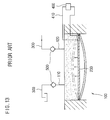
- FIG. 13 is a conceptual view illustrating a conventional piezoelectric pump.
- the conventional piezoelectric pump includes a piezoelectric actuator 100 having a suction port 110 and a discharge port 120, and a piezoelectric device 200 installed in the piezoelectric actuator 100.
- the suction port 110 and the discharge port 120 communicate with fluid pipes 300, respectively.
- Ends of the piezoelectric device 200 are connected to a controller 400 by lead wires 410 such that the controller 400 applies an electric field to the piezoelectric device 200 to pump a fluid while being deflected.
- the fluid supplied through the fluid pipe 300 is fed into the piezoelectric actuator 100 through the suction port 110, and the fed fluid is pumped when a voltage is applied to the piezoelectric device 200 by the controller 400 and then is discharged out through the discharge port 120.
- the conventional piezoelectric pump includes check valves 500 respectively installed to the suction port 110 and the discharge port 120 to prevent the fluid from flowing backward when the fluid is pumped by the deflection of the piezoelectric device 200.
- the conventional piezoelectric pump is provided independently from the fluid pipe 300 and the check valves 500 for preventing fluid from flowing backward are provided independently from the pump, the conventional piezoelectric pump is not suitable for minimizing electronic products and medical equipment because it is difficult to make the piezoelectric pump in a small size.
- the present invention has been made in view of the above problems, and it is an aspect of the present invention to provide an ultrasonic piezoelectric pump in which: a piezoelectric actuator is installed at a center of a fluid pipe; a plurality of fluid-flow holes is formed around the piezoelectric actuator; and a tapered nozzle is tapered forward and downwardly in front of the piezoelectric actuator to force a fluid to be easily discharged and to have difficulty to flow backward so that a fluid can be smoothly pumped by the piezoelectric actuator without a check valve while preventing the fluid from flowing backward.
- an ultrasonic piezoelectric pump comprising: a fluid pipe having a hollow part formed therein to permit a fluid to flow from a fluid source; a piezoelectric actuator inserted into the hollow part and including a piezoelectric device and a plurality of fluid holes; a controller connected to a lead wire to apply a driving power to the piezoelectric device; and a tapered nozzle inserted into the hollow part in front of the piezoelectric actuator and tapered forward and downwardly.
- the piezoelectric actuator comprises: a case having a through-hole formed at the center thereof; a frame, inserted into the through-hole, to which the piezoelectric device is installed; and the fluid holes formed in the vicinity of the frame to penetrate the front side to the rear side of the case.
- the piezoelectric device comprises a unimorph comprising: a thin plate; and a piezoelectric ceramic contacting a side of the thin plate.
- the piezoelectric device comprises: a case having a through-hole formed at the center thereof; a pipe-shaped cylinder inserted into the through-hole; a rear plate fixed to the rear side of the cylinder to close the rear side of the cylinder; a front plate contacting an inner wall of the cylinder and used as a piston; the piezoelectric device, provided to connect the rear plate to the front plate, in which a plurality of piezoelectric ceramics are laminated; and the fluid holes formed in the vicinity of the cylinder to penetrate the front side to the rear side of the case.
- the front plate further comprises a circular rubber ring to seal the case and to prevent the fluid from entering.
- the piezoelectric actuator comprises: a case having a through-hole formed at the center thereof; a frame inserted into the through-hole; a piezoelectric ceramic provided in the frame to generate a deflection in the radial direction; an elastic member contacting the front side of the piezoelectric ceramic, a part of the elastic member inserted into the frame and another part of the elastic member protruding from the front side of the frame, and the protruded part having a smaller diameter than that of the part inserted into the frame and vibrating due to ultrasonic waves applied to the piezoelectric device; a fixed body to fix the elastic member to the frame, and through which the elastic member penetrates; and the fluid holes formed in the vicinity of the frame to penetrate the front side to the rear side of the case.
- the ultrasonic piezoelectric pump further comprises a distance adjusting circular ring provided in the fluid pipe to adjust a distance between the piezoelectric actuator and the tapered nozzle.
- FIG. 1 is a sectional view illustrating an ultrasonic piezoelectric pump according to a first embodiment of the present invention.
- the ultrasonic piezoelectric pump includes a fluid pipe 1, a piezoelectric pump 2, a controller 3, and a tapered nozzle 4.
- the fluid pipe 1 has a hollow part 11 formed therein through which a fluid flows from a fluid source.
- the piezoelectric actuator 2 is inserted into the hollow part 11 and includes a piezoelectric device 23 and a plurality of fluid holes 24.
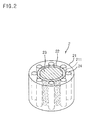
- FIG. 2 is a perspective view illustrating the piezoelectric actuator of FIG. 1 .
- the actuator 2 includes a case 21 with through-holes 211 formed at the center thereof, a frame 22, inserted into the through-holes 211, in which the piezoelectric device 23 is installed to the front side of the frame 22, and the plurality of fluid holes 24 formed in the vicinity of the frame 22 to penetrate the front side to the rear side of the case 21 and to permit the fluid supplied to the fluid pipe 1 to flow therethrough.
- the piezoelectric device 23 is made in the form of a unimorph having a thin plate 231 and a piezoelectric ceramic 232 contacting one side of the thin plate 231, but may be made in the form of a bimorph, as illustrated in FIG. 4 , having a thin plate 231 and piezoelectric ceramics 232 contacting sides of the thin plate 231.
- the controller 3 is connected to the piezoelectric device 23 through a lead wire 31 to apply a driving power to the piezoelectric device 23.
- the tapered nozzle 4 has a tapered opening 41 inserted into the hollow part 11 in front of the piezoelectric actuator and tapered forward and downwardly. Since the opening 41 is tapered forward and downwardly, the fluid can be easily discharged and has difficulty to flow backward so that the backflow of the fluid can be prevented.
- FIG. 5 is a sectional view illustrating an ultrasonic piezoelectric pump according to a second embodiment of the present invention.
- structures and operations of the same components as those of FIG. 1 will be omitted.
- a distance adjusting circular ring 5 is provided in the hollow part 11 of the fluid pipe 1 between the piezoelectric actuator 2 and the tapered nozzle 4 to adjust a distance from the piezoelectric actuator 2 and the tapered nozzle 4.
- the distance between the piezoelectric actuator 2 and the tapered nozzle 4 is preferably adjusted by the distance adjusting circular ring 5 to optimize the transmission of kinetic energy of the fluid.
- FIG. 6 is a sectional view illustrating an ultrasonic piezoelectric pump according to a third embodiment of the present invention, and structures and operations of the same components as those of the first and second embodiments of the present invention will be omitted.
- the ultrasonic piezoelectric pump includes a fluid pipe 1, a piezoelectric actuator 2, a controller 3, and a tapered nozzle 4.
- FIG. 7 is a perspective view illustrating the actuator in FIG. 6 , and as illustrated in FIGS. 6 and 7 , the actuator 7 includes a case 21, a cylinder 25, a rear plate 26, a front plate 27, and a piezoelectric device 23.
- the case has a through-hole 211 formed at the center and the cylinder 25 has a pipe shape and is inserted into the through-hole 211.
- the case 21 has a plurality of fluid holes 24 penetrating from the front side of the case 21 to the rear side thereof in the vicinity of the cylinder 25 to permit the fluid to flow from the front side to the rear side of the case 21.
- the rear plate 26 is fixed to the rear side of the cylinder 25 to close the rear side of the cylinder 25 and the front plate 27 contacts the inner wall of the cylinder 25 and plays a role of a reciprocating piston.
- the piezoelectric device 23 connects the rear plate 26 to the front plate 27 and a plurality of piezoelectric ceramics 232 are laminated on the piezoelectric device 23 such that the piezoelectric device 23 plays a role of a rod for moving the front plate 27 forward and backward due to an external applied voltage.
- a distance adjusting circular ring 5 is provided in the hollow part 11 of the fluid pipe 1 between the piezoelectric actuator 2 and the tapered nozzle 4 to adjust a distance between the piezoelectric actuator 2 and the tapered nozzle 4.
- FIG. 8 is a sectional view illustrating another example of the actuator in FIG. 6 .
- a circular rubber ring 271 is provided to the front plate 27 to seal the case to prevent a fluid from entering.
- the controller 3 is connected to the piezoelectric device 23 by the lead wire 31 to apply a driving power to the piezoelectric device 23.
- the tapered nozzle 4 is inserted into the hollow part 11 in front of the piezoelectric actuator and has an opening 41 tapered downwardly and forwardly. Since the opening 41 is tapered forward and downwardly, the fluid is easily discharged and has difficulty to flow backward so that the fluid can be prevented from flowing backward.
- the fluid is pumped using the ultrasonic piezoelectric pump according to the first to third embodiments of the present invention by adjusting the voltage applied to the piezoelectric device 23 such that the voltage, as illustrated in FIG. 9 , has a waveform of a voltage slowly increasing during the suctioning of the fluid and quickly decreasing during the discharge of the fluid.
- the frequency of the voltage is adjusted to have a waveform of the voltage such that the piezoelectric device is quickly deformed to discharge the fluid and slowly returns to suction the fluid, therefore the fluid can be smoothly discharged.
- the ultrasonic piezoelectric device (?) transmits kinetic energy to fluid particles such that the fluid particles flow due to an inertial force.
- the movement of the fluid caused by the inertial force resonates in association with the flow frequency of the fluid so that heat transfer can be accelerated.
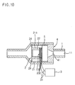
- FIG. 10 is a sectional view illustrating an ultrasonic piezoelectric pump according to a fourth embodiment of the present invention.
- the ultrasonic piezoelectric pump includes a piezoelectric pump 1, a piezoelectric actuator 2, a controller 3, and a tapered nozzle 4.
- the fluid pump 1 has a hollow part 11 formed therein through which a fluid flows from a fluid source.
- the piezoelectric actuator 2 is inserted into and fixed in the hollow part 11, and has a piezoelectric device 23 and a plurality of fluid holes 24.
- the actuator 2 includes a case 21 having a through-hole 211 formed at the center, a frame 22, inserted into the through-hole 211, to which the piezoelectric device 23 is installed, and a plurality of fluid holes 24 formed in the vicinity of the frame 22 to penetrate the front side to the rear side of the case 21 and to permit the fluid supplied to the fluid pipe 1 to flow therethrough.
- the piezoelectric device 23 may include a multi-layer piezoelectric disc having a plurality of thin piezoelectric ceramics 232 which resonate in the thickness direction by the application of ultrasonic waves.
- controller 3 is connected to the piezoelectric device 23 by a lead wire 21 to adjust a frequency applied to the piezoelectric device 23.
- the controller 3 applies ultrasonic waves higher than 5 MHz to the piezoelectric device 23 having several tens of piezoelectric ceramics 232 through the lead wire 31 so that vibration in the thickness direction is obtained to discharge the fluid through the tapered nozzle 4.
- a distance adjusting circular ring 5 may be provided in the hollow part 11 of the fluid pipe 1 between the piezoelectric actuator 2 and the tapered nozzle 4 to adjust a distance from the piezoelectric actuator 2 and the tapered nozzle 4.
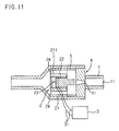
- FIG. 11 is a sectional view illustrating an ultrasonic piezoelectric pump according to a fifth embodiment of the present invention and FIG. 12 is an enlarged view illustrating the piezoelectric device 23 in FIG. 23.
- the ultrasonic piezoelectric pump includes a fluid pipe 1, a piezoelectric actuator 2, a controller 3, and a tapered nozzle 4.
- the piezoelectric actuator 2 includes a case 21 with through-holes 211 formed at the center thereof, a frame 22 inserted into the through-holes 211, the piezoelectric device 23 installed in the frame 22, and a plurality of fluid holes 24 formed in the vicinity of the frame 22 to penetrate the front side to the rear side of the case 21.
- the piezoelectric device 23 includes a piezoelectric ceramic 232a, an elastic member 232b, and a fixed body 234.
- the piezoelectric ceramic 23a is provided in the frame 22 and generates deflection in the radial direction.
- the elastic member 232b contacts the front side of the piezoelectric ceramic 232a, is partially inserted into the frame 22, and is partially protruded outwardly from the front side of the frame 22.
- the part of the elastic member 232b protruded from the frame 22 has a diameter smaller than that of the part of the elastic member 232b inserted into the frame 22, and due to the small diameter, generates a large deflection.
- the elastic member 232b vibrates at ultrasonic waves with a preset frequency applied to the piezoelectric ceramic 232a in the longitudinal direction.
- the elastic member 232b does not vibrate when the frequency applied to the piezoelectric ceramic 232a is low, but vibrates in the longitudinal direction by which ultrasonic vibration is transmitted thereto when the frequency applied to the piezoelectric ceramic 232a is in the form of ultrasonic waves with several hundreds of kHz or higher.
- the elastic member 232b is inserted into the fixed body 234 to penetrate the same, and the fixed body 234 fixes the elastic member 232b to the frame 22.
- the controller 3 is connected to the piezoelectric device 23 by the lead wire 31 to adjust the frequency applied to the piezoelectric device 23.
- the intensity of the frequency applied to the piezoelectric device by the controller 3 is set by modes to vibrate only the piezoelectric ceramic 232a generating a radial directional deflection or to apply a higher frequency to vibrate the piezoelectric ceramic 232a and all the piezoelectric ceramics 232a generating the longitudinal deflection.
- the fluid is pumped using the piezoelectric actuator installed at the center of the fluid pipe and the tapered nozzle tapered forward and downwardly without a check valve so that the fluid is smoothly pumped.
- the ultrasonic piezoelectric pump does not include the fluid pipe separated from the fluid pump and a check valve, the ultrasonic piezoelectric pump can be made in a simple structure and is easily made in a small size.
- the ultrasonic piezoelectric pump is described for use with a fluid
- the ultrasonic piezoelectric pump can be used for gas such as air and its description will be omitted since the structure and operation thereof is identical to the case of for use with the fluid.
- the piezoelectric actuator is installed at the center of the fluid pipe, a plurality of fluid-flow holes is formed around the piezoelectric actuator, and the tapered nozzle is tapered forward and downwardly in front of the piezoelectric actuator to force the fluid to be easily discharged and to have difficulty flowing backward so that the fluid can be smoothly pumped by the piezoelectric actuator without a check valve while preventing the fluid from flowing backward and the pumping efficiency can be improved.
- a voltage applied to the piezoelectric device is adjusted to quickly deform the piezoelectric device for the fluid discharge and a frequency is adjusted to have a voltage waveform to force the piezoelectric device to be restored slowly so that a fluid can be smoothly discharged.
- the piezoelectric device is driven by ultrasonic waves to force the fluid to flow while causing flow resonance so that efficiency of heat transfer can be improved.
- the flow of a fluid is controlled by the piezoelectric ceramic vibrating in the longitudinal direction or in the radial direction by the application of ultrasonic waves and the elastic member vibrating in the longitudinal direction by ultrasonic waves applied to the piezoelectric device, so that the fluid can be smoothly pumped without the backflow by the piezoelectric actuator without a check valve and the ultrasonic piezoelectric pump can be applied to small sized products.
Landscapes
- Engineering & Computer Science (AREA)
- Mechanical Engineering (AREA)
- General Engineering & Computer Science (AREA)
- Reciprocating Pumps (AREA)
Abstract
Description
- The present invention relates to a piezoelectric pump, and more particularly, to an ultrasonic piezoelectric pump in which a piezoelectric pump is integrated with a fluid pipe without a check valve so that the structure can be simplified.
- In general, since parts for small sized electronic products and medical equipment possibly malfunction or are damaged due to heat generated therein because degree of integration of transistors is improved, cooling of the electronic parts is becoming a critical issue in electronic apparatuses using small electronic parts.
- It is proposed a refrigerant circulation system using a piezoelectric pump, as a solution for cooling the small sized electronic components, for suctioning liquid refrigerant and for vibrating the liquid refrigerant by applying a force to the liquid refrigerant to discharge the refrigerant in a desired phase(?).
-
FIG. 13 is a conceptual view illustrating a conventional piezoelectric pump. Referring toFIG. 13 , the conventional piezoelectric pump includes apiezoelectric actuator 100 having asuction port 110 and adischarge port 120, and apiezoelectric device 200 installed in thepiezoelectric actuator 100. Thesuction port 110 and thedischarge port 120 communicate withfluid pipes 300, respectively. - Ends of the
piezoelectric device 200 are connected to acontroller 400 bylead wires 410 such that thecontroller 400 applies an electric field to thepiezoelectric device 200 to pump a fluid while being deflected. - In this structure, the fluid supplied through the
fluid pipe 300 is fed into thepiezoelectric actuator 100 through thesuction port 110, and the fed fluid is pumped when a voltage is applied to thepiezoelectric device 200 by thecontroller 400 and then is discharged out through thedischarge port 120. - The conventional piezoelectric pump includes
check valves 500 respectively installed to thesuction port 110 and thedischarge port 120 to prevent the fluid from flowing backward when the fluid is pumped by the deflection of thepiezoelectric device 200. - As such, since the conventional piezoelectric pump is provided independently from the
fluid pipe 300 and thecheck valves 500 for preventing fluid from flowing backward are provided independently from the pump, the conventional piezoelectric pump is not suitable for minimizing electronic products and medical equipment because it is difficult to make the piezoelectric pump in a small size. - Therefore, the present invention has been made in view of the above problems, and it is an aspect of the present invention to provide an ultrasonic piezoelectric pump in which: a piezoelectric actuator is installed at a center of a fluid pipe; a plurality of fluid-flow holes is formed around the piezoelectric actuator; and a tapered nozzle is tapered forward and downwardly in front of the piezoelectric actuator to force a fluid to be easily discharged and to have difficulty to flow backward so that a fluid can be smoothly pumped by the piezoelectric actuator without a check valve while preventing the fluid from flowing backward.
- It is another aspect of the present invention to provide an ultrasonic piezoelectric pump in which a voltage applied to a piezoelectric device is adjusted to quickly deform the piezoelectric device for the fluid discharge and a frequency is adjusted to have a voltage waveform to force the piezoelectric device to be restored slowly so that a fluid can be smoothly discharged.
- It is still another aspect of the present invention to provide an ultrasonic piezoelectric pump, a piezoelectric device of which is driven by ultrasonic waves to force a fluid to flow while causing flow resonance so that efficiency of heat transfer can be improved.
- In order to achieve the object, there is provided an ultrasonic piezoelectric pump comprising: a fluid pipe having a hollow part formed therein to permit a fluid to flow from a fluid source; a piezoelectric actuator inserted into the hollow part and including a piezoelectric device and a plurality of fluid holes; a controller connected to a lead wire to apply a driving power to the piezoelectric device; and a tapered nozzle inserted into the hollow part in front of the piezoelectric actuator and tapered forward and downwardly.
- The piezoelectric actuator comprises: a case having a through-hole formed at the center thereof; a frame, inserted into the through-hole, to which the piezoelectric device is installed; and the fluid holes formed in the vicinity of the frame to penetrate the front side to the rear side of the case.
- The piezoelectric device comprises a unimorph comprising: a thin plate; and a piezoelectric ceramic contacting a side of the thin plate.
- The piezoelectric device comprises: a case having a through-hole formed at the center thereof; a pipe-shaped cylinder inserted into the through-hole; a rear plate fixed to the rear side of the cylinder to close the rear side of the cylinder; a front plate contacting an inner wall of the cylinder and used as a piston; the piezoelectric device, provided to connect the rear plate to the front plate, in which a plurality of piezoelectric ceramics are laminated; and the fluid holes formed in the vicinity of the cylinder to penetrate the front side to the rear side of the case.
- The front plate further comprises a circular rubber ring to seal the case and to prevent the fluid from entering.
- The piezoelectric actuator comprises: a case having a through-hole formed at the center thereof; a frame inserted into the through-hole; a piezoelectric ceramic provided in the frame to generate a deflection in the radial direction; an elastic member contacting the front side of the piezoelectric ceramic, a part of the elastic member inserted into the frame and another part of the elastic member protruding from the front side of the frame, and the protruded part having a smaller diameter than that of the part inserted into the frame and vibrating due to ultrasonic waves applied to the piezoelectric device; a fixed body to fix the elastic member to the frame, and through which the elastic member penetrates; and the fluid holes formed in the vicinity of the frame to penetrate the front side to the rear side of the case.
- The ultrasonic piezoelectric pump further comprises a distance adjusting circular ring provided in the fluid pipe to adjust a distance between the piezoelectric actuator and the tapered nozzle.
- The above and other aspects, features and other advantages of the present invention will be more clearly understood from the following detailed description taken in conjunction with the accompanying drawings, in which:
-
FIG. 1 is a sectional view illustrating an ultrasonic piezoelectric pump according to an embodiment of the present invention; -
FIG. 2 is a perspective view illustrating an actuator inFIG. 1 ; -
FIGS. 3 to 5 are sectional views illustrating a piezoelectric device inFIG. 1 ; -
FIG. 6 is a sectional view illustrating an ultrasonic piezoelectric pump according to another embodiment of the present invention; -
FIG. 7 is a sectional view illustrating an ultrasonic piezoelectric pump according to still another embodiment of the present invention; -
FIG. 8 is a perspective view illustrating an actuator inFIG. 7 ; -
FIG. 9 is a perspective view illustrating another example of the actuator inFIG. 7 ; -
FIG. 10 is a sectional view illustrating an ultrasonic piezoelectric pump according to still embodiment of the present invention; -
FIG. 11 is a sectional view illustrating a piezoelectric device inFIG. 10 ; -
FIG. 12 is a waveform chart illustrating a voltage applied to the piezoelectric device according to an embodiment of the present invention; and -
FIG. 13 is a conceptual view illustrating a conventional piezoelectric pump. - Hereinafter, preferred embodiments of the present invention will be described in detail with reference to the accompanying drawings.
-
FIG. 1 is a sectional view illustrating an ultrasonic piezoelectric pump according to a first embodiment of the present invention. The ultrasonic piezoelectric pump includes a fluid pipe 1, apiezoelectric pump 2, acontroller 3, and atapered nozzle 4. - The fluid pipe 1 has a
hollow part 11 formed therein through which a fluid flows from a fluid source. - Moreover, the
piezoelectric actuator 2 is inserted into thehollow part 11 and includes apiezoelectric device 23 and a plurality offluid holes 24. -
FIG. 2 is a perspective view illustrating the piezoelectric actuator ofFIG. 1 . Theactuator 2 includes acase 21 with through-holes 211 formed at the center thereof, aframe 22, inserted into the through-holes 211, in which thepiezoelectric device 23 is installed to the front side of theframe 22, and the plurality offluid holes 24 formed in the vicinity of theframe 22 to penetrate the front side to the rear side of thecase 21 and to permit the fluid supplied to the fluid pipe 1 to flow therethrough. - In this case, the
piezoelectric device 23, as illustrated inFIG. 3 , is made in the form of a unimorph having athin plate 231 and apiezoelectric ceramic 232 contacting one side of thethin plate 231, but may be made in the form of a bimorph, as illustrated inFIG. 4 , having athin plate 231 andpiezoelectric ceramics 232 contacting sides of thethin plate 231. - The
controller 3 is connected to thepiezoelectric device 23 through alead wire 31 to apply a driving power to thepiezoelectric device 23. - The
tapered nozzle 4 has atapered opening 41 inserted into thehollow part 11 in front of the piezoelectric actuator and tapered forward and downwardly. Since theopening 41 is tapered forward and downwardly, the fluid can be easily discharged and has difficulty to flow backward so that the backflow of the fluid can be prevented. -
FIG. 5 is a sectional view illustrating an ultrasonic piezoelectric pump according to a second embodiment of the present invention. Hereinafter, structures and operations of the same components as those ofFIG. 1 will be omitted. - Referring to
FIG. 5 , a distance adjustingcircular ring 5 is provided in thehollow part 11 of the fluid pipe 1 between thepiezoelectric actuator 2 and thetapered nozzle 4 to adjust a distance from thepiezoelectric actuator 2 and thetapered nozzle 4. - In this case, the distance between the
piezoelectric actuator 2 and thetapered nozzle 4 is preferably adjusted by the distance adjustingcircular ring 5 to optimize the transmission of kinetic energy of the fluid. -
FIG. 6 is a sectional view illustrating an ultrasonic piezoelectric pump according to a third embodiment of the present invention, and structures and operations of the same components as those of the first and second embodiments of the present invention will be omitted. - According to this embodiment, the ultrasonic piezoelectric pump includes a fluid pipe 1, a
piezoelectric actuator 2, acontroller 3, and atapered nozzle 4. -
FIG. 7 is a perspective view illustrating the actuator inFIG. 6 , and as illustrated inFIGS. 6 and7 , the actuator 7 includes acase 21, acylinder 25, arear plate 26, afront plate 27, and apiezoelectric device 23. - The case has a through-
hole 211 formed at the center and thecylinder 25 has a pipe shape and is inserted into the through-hole 211. - Moreover, the
case 21 has a plurality offluid holes 24 penetrating from the front side of thecase 21 to the rear side thereof in the vicinity of thecylinder 25 to permit the fluid to flow from the front side to the rear side of thecase 21. - The
rear plate 26 is fixed to the rear side of thecylinder 25 to close the rear side of thecylinder 25 and thefront plate 27 contacts the inner wall of thecylinder 25 and plays a role of a reciprocating piston. - The
piezoelectric device 23 connects therear plate 26 to thefront plate 27 and a plurality ofpiezoelectric ceramics 232 are laminated on thepiezoelectric device 23 such that thepiezoelectric device 23 plays a role of a rod for moving thefront plate 27 forward and backward due to an external applied voltage. - Moreover, a distance adjusting
circular ring 5 is provided in thehollow part 11 of the fluid pipe 1 between thepiezoelectric actuator 2 and thetapered nozzle 4 to adjust a distance between thepiezoelectric actuator 2 and thetapered nozzle 4. -
FIG. 8 is a sectional view illustrating another example of the actuator inFIG. 6 . Referring toFIGS. 6 to 8 , acircular rubber ring 271 is provided to thefront plate 27 to seal the case to prevent a fluid from entering. - By doing so, the fluid flowing from the hollow part of the fluid pipe 1 to outside the
case 21 is prevented from entering the actuator. - The
controller 3 is connected to thepiezoelectric device 23 by thelead wire 31 to apply a driving power to thepiezoelectric device 23. - Meanwhile, the
tapered nozzle 4 is inserted into thehollow part 11 in front of the piezoelectric actuator and has an opening 41 tapered downwardly and forwardly. Since theopening 41 is tapered forward and downwardly, the fluid is easily discharged and has difficulty to flow backward so that the fluid can be prevented from flowing backward. - The fluid is pumped using the ultrasonic piezoelectric pump according to the first to third embodiments of the present invention by adjusting the voltage applied to the
piezoelectric device 23 such that the voltage, as illustrated inFIG. 9 , has a waveform of a voltage slowly increasing during the suctioning of the fluid and quickly decreasing during the discharge of the fluid. - In other words, the frequency of the voltage is adjusted to have a waveform of the voltage such that the piezoelectric device is quickly deformed to discharge the fluid and slowly returns to suction the fluid, therefore the fluid can be smoothly discharged.
- According to the embodiments of the present invention, the ultrasonic piezoelectric device (?) transmits kinetic energy to fluid particles such that the fluid particles flow due to an inertial force.
- In other words, the movement of the fluid caused by the inertial force resonates in association with the flow frequency of the fluid so that heat transfer can be accelerated.
-
FIG. 10 is a sectional view illustrating an ultrasonic piezoelectric pump according to a fourth embodiment of the present invention. The ultrasonic piezoelectric pump includes a piezoelectric pump 1, apiezoelectric actuator 2, acontroller 3, and atapered nozzle 4. - The fluid pump 1 has a
hollow part 11 formed therein through which a fluid flows from a fluid source. - Moreover, the
piezoelectric actuator 2 is inserted into and fixed in thehollow part 11, and has apiezoelectric device 23 and a plurality of fluid holes 24. - Here, the
actuator 2 includes acase 21 having a through-hole 211 formed at the center, aframe 22, inserted into the through-hole 211, to which thepiezoelectric device 23 is installed, and a plurality of fluid holes 24 formed in the vicinity of theframe 22 to penetrate the front side to the rear side of thecase 21 and to permit the fluid supplied to the fluid pipe 1 to flow therethrough. - The
piezoelectric device 23 may include a multi-layer piezoelectric disc having a plurality of thinpiezoelectric ceramics 232 which resonate in the thickness direction by the application of ultrasonic waves. - Moreover, the
controller 3 is connected to thepiezoelectric device 23 by alead wire 21 to adjust a frequency applied to thepiezoelectric device 23. - In other words, the
controller 3 applies ultrasonic waves higher than 5 MHz to thepiezoelectric device 23 having several tens ofpiezoelectric ceramics 232 through thelead wire 31 so that vibration in the thickness direction is obtained to discharge the fluid through the taperednozzle 4. - Here, a distance adjusting
circular ring 5 may be provided in thehollow part 11 of the fluid pipe 1 between thepiezoelectric actuator 2 and the taperednozzle 4 to adjust a distance from thepiezoelectric actuator 2 and the taperednozzle 4. -
FIG. 11 is a sectional view illustrating an ultrasonic piezoelectric pump according to a fifth embodiment of the present invention andFIG. 12 is an enlarged view illustrating thepiezoelectric device 23 in FIG. 23. Referring toFIG. 11 , the ultrasonic piezoelectric pump includes a fluid pipe 1, apiezoelectric actuator 2, acontroller 3, and atapered nozzle 4. - Here, the
piezoelectric actuator 2 includes acase 21 with through-holes 211 formed at the center thereof, aframe 22 inserted into the through-holes 211, thepiezoelectric device 23 installed in theframe 22, and a plurality of fluid holes 24 formed in the vicinity of theframe 22 to penetrate the front side to the rear side of thecase 21. - The
piezoelectric device 23 includes a piezoelectric ceramic 232a, anelastic member 232b, and afixed body 234. - Here, the piezoelectric ceramic 23a is provided in the
frame 22 and generates deflection in the radial direction. - The
elastic member 232b contacts the front side of the piezoelectric ceramic 232a, is partially inserted into theframe 22, and is partially protruded outwardly from the front side of theframe 22. - The part of the
elastic member 232b protruded from theframe 22 has a diameter smaller than that of the part of theelastic member 232b inserted into theframe 22, and due to the small diameter, generates a large deflection. - The
elastic member 232b vibrates at ultrasonic waves with a preset frequency applied to the piezoelectric ceramic 232a in the longitudinal direction. - In other words, the
elastic member 232b does not vibrate when the frequency applied to the piezoelectric ceramic 232a is low, but vibrates in the longitudinal direction by which ultrasonic vibration is transmitted thereto when the frequency applied to the piezoelectric ceramic 232a is in the form of ultrasonic waves with several hundreds of kHz or higher. - Meanwhile, the
elastic member 232b is inserted into the fixedbody 234 to penetrate the same, and the fixedbody 234 fixes theelastic member 232b to theframe 22. - The
controller 3 is connected to thepiezoelectric device 23 by thelead wire 31 to adjust the frequency applied to thepiezoelectric device 23. - In the fifth embodiment of the present invention, the intensity of the frequency applied to the piezoelectric device by the
controller 3 is set by modes to vibrate only the piezoelectric ceramic 232a generating a radial directional deflection or to apply a higher frequency to vibrate the piezoelectric ceramic 232a and all thepiezoelectric ceramics 232a generating the longitudinal deflection. - As such, according to the embodiments of the present invention, the fluid is pumped using the piezoelectric actuator installed at the center of the fluid pipe and the tapered nozzle tapered forward and downwardly without a check valve so that the fluid is smoothly pumped. Moreover, since the ultrasonic piezoelectric pump does not include the fluid pipe separated from the fluid pump and a check valve, the ultrasonic piezoelectric pump can be made in a simple structure and is easily made in a small size.
- Meanwhile, although the ultrasonic piezoelectric pump is described for use with a fluid, the ultrasonic piezoelectric pump can be used for gas such as air and its description will be omitted since the structure and operation thereof is identical to the case of for use with the fluid.
- As described above, according to the ultrasonic piezoelectric pump, the piezoelectric actuator is installed at the center of the fluid pipe, a plurality of fluid-flow holes is formed around the piezoelectric actuator, and the tapered nozzle is tapered forward and downwardly in front of the piezoelectric actuator to force the fluid to be easily discharged and to have difficulty flowing backward so that the fluid can be smoothly pumped by the piezoelectric actuator without a check valve while preventing the fluid from flowing backward and the pumping efficiency can be improved.
- Moreover, a voltage applied to the piezoelectric device is adjusted to quickly deform the piezoelectric device for the fluid discharge and a frequency is adjusted to have a voltage waveform to force the piezoelectric device to be restored slowly so that a fluid can be smoothly discharged.
- According to the ultrasonic piezoelectric pump, the piezoelectric device is driven by ultrasonic waves to force the fluid to flow while causing flow resonance so that efficiency of heat transfer can be improved.
- According to the ultrasonic piezoelectric pump, the flow of a fluid is controlled by the piezoelectric ceramic vibrating in the longitudinal direction or in the radial direction by the application of ultrasonic waves and the elastic member vibrating in the longitudinal direction by ultrasonic waves applied to the piezoelectric device, so that the fluid can be smoothly pumped without the backflow by the piezoelectric actuator without a check valve and the ultrasonic piezoelectric pump can be applied to small sized products.
- Although the preferred embodiments of the present invention have been disclosed for illustrative purposes, those skilled in the art will appreciate that various modifications, additions and substitutions are possible, without departing from the scope and spirit of the invention as disclosed in the accompanying claims.
Claims (9)
- An ultrasonic piezoelectric pump comprising:a fluid pipe having a hollow part formed therein to permit a fluid to flow from a fluid source;a piezoelectric actuator inserted into the hollow part and including a piezoelectric device and a plurality of fluid holes;a controller connected to a lead wire to apply a driving power to the piezoelectric device; anda tapered nozzle inserted into the hollow part in front of the piezoelectric actuator and tapered forward and downwardly.
- The ultrasonic piezoelectric pump according to claim 1, wherein the piezoelectric actuator comprises:a case having a through-hole formed at the center thereof;a frame, inserted into the through-hole, to which the piezoelectric device is installed; andthe fluid holes formed in the vicinity of the frame to penetrate the front side to the rear side of the case.
- The ultrasonic piezoelectric pump according to claim 2, wherein the piezoelectric device comprises a unimorph comprising:a thin plate; anda piezoelectric ceramic contacting a side of the thin plate.
- The ultrasonic piezoelectric pump according to claim 2, wherein the piezoelectric device comprises a unimorph comprising:a thin plate; anda piezoelectric ceramic contacting sides of the thin plate.
- The ultrasonic piezoelectric pump according to claim 2, wherein the piezoelectric device comprises a multi-layer piezoelectric disc having a plurality of thin piezoelectric ceramics and resonating in the thickness direction.
- The ultrasonic piezoelectric pump according to claim 1, wherein the piezoelectric device comprises:a case having a through-hole formed at the center thereof;a pipe-shaped cylinder inserted into the through-hole;a rear plate fixed to the rear side of the cylinder to close the rear side of the cylinder;a front plate contacting an inner wall of the cylinder and used as a piston;the piezoelectric device, provided to connect the rear plate to the front plate, in which a plurality of piezoelectric ceramics are laminated; andthe fluid holes formed in the vicinity of the cylinder to penetrate the front side to the rear side of the case.
- The ultrasonic piezoelectric pump according to claim 6, wherein the front plate further comprises a circular rubber ring to seal the case and to prevent the fluid from entering.
- The ultrasonic piezoelectric pump according to claim 1, wherein the piezoelectric actuator comprises:a case having a through-hole formed at the center thereof;a frame inserted into the through-hole;a piezoelectric ceramic provided in the frame to generate a deflection in the radial direction;an elastic member contacting the front side of the piezoelectric ceramic, a part of the elastic member inserted into the frame and another part of the elastic member protruding from the front side of the frame, and the protruded part having a smaller diameter than that of the part inserted into the frame and vibrating due to ultrasonic waves applied to the piezoelectric device;a fixed body to fix the elastic member to the frame, and through which the elastic member penetrates; andthe fluid holes formed in the vicinity of the frame to penetrate the front side to the rear side of the case.
- The ultrasonic piezoelectric pump according to any one of claims 1 to 8, further comprising a distance adjusting circular ring provided in the fluid pipe to adjust a distance between the piezoelectric actuator and the tapered nozzle.
Priority Applications (2)
| Application Number | Priority Date | Filing Date | Title |
|---|---|---|---|
| AT08004605T ATE525571T1 (en) | 2008-03-12 | 2008-03-12 | PIEZOELECTRIC ULTRASONIC PUMP |
| EP08004605A EP2101060B1 (en) | 2008-03-12 | 2008-03-12 | Ultrasonic piezoelectric pump |
Applications Claiming Priority (1)
| Application Number | Priority Date | Filing Date | Title |
|---|---|---|---|
| EP08004605A EP2101060B1 (en) | 2008-03-12 | 2008-03-12 | Ultrasonic piezoelectric pump |
Publications (2)
| Publication Number | Publication Date |
|---|---|
| EP2101060A1 true EP2101060A1 (en) | 2009-09-16 |
| EP2101060B1 EP2101060B1 (en) | 2011-09-21 |
Family
ID=39469499
Family Applications (1)
| Application Number | Title | Priority Date | Filing Date |
|---|---|---|---|
| EP08004605A Not-in-force EP2101060B1 (en) | 2008-03-12 | 2008-03-12 | Ultrasonic piezoelectric pump |
Country Status (2)
| Country | Link |
|---|---|
| EP (1) | EP2101060B1 (en) |
| AT (1) | ATE525571T1 (en) |
Cited By (4)
| Publication number | Priority date | Publication date | Assignee | Title |
|---|---|---|---|---|
| CN102261324A (en) * | 2011-06-21 | 2011-11-30 | 南京航空航天大学 | Valveless piezoelectric pump of conical spiral flow tube |
| CN111486086A (en) * | 2020-05-29 | 2020-08-04 | 成都航空职业技术学院 | A lightweight piezoelectric hydraulic pump suitable for long-term work |
| CN111550390A (en) * | 2020-05-20 | 2020-08-18 | 成都航空职业技术学院 | A piezoelectric hydraulic pump |
| DE102020206836A1 (en) | 2020-06-02 | 2021-12-02 | Robert Bosch Gesellschaft mit beschränkter Haftung | Feed pump |
Citations (3)
| Publication number | Priority date | Publication date | Assignee | Title |
|---|---|---|---|---|
| US5004945A (en) * | 1988-09-26 | 1991-04-02 | Nippondenso Co., Ltd. | Piezoelectric type actuator |
| WO1997024528A2 (en) | 1995-12-31 | 1997-07-10 | Micro Infusion Ltd. | Multichannel microdosing apparatus |
| US20060232166A1 (en) * | 2005-04-13 | 2006-10-19 | Par Technologies Llc | Stacked piezoelectric diaphragm members |
-
2008
- 2008-03-12 EP EP08004605A patent/EP2101060B1/en not_active Not-in-force
- 2008-03-12 AT AT08004605T patent/ATE525571T1/en not_active IP Right Cessation
Patent Citations (3)
| Publication number | Priority date | Publication date | Assignee | Title |
|---|---|---|---|---|
| US5004945A (en) * | 1988-09-26 | 1991-04-02 | Nippondenso Co., Ltd. | Piezoelectric type actuator |
| WO1997024528A2 (en) | 1995-12-31 | 1997-07-10 | Micro Infusion Ltd. | Multichannel microdosing apparatus |
| US20060232166A1 (en) * | 2005-04-13 | 2006-10-19 | Par Technologies Llc | Stacked piezoelectric diaphragm members |
Cited By (5)
| Publication number | Priority date | Publication date | Assignee | Title |
|---|---|---|---|---|
| CN102261324A (en) * | 2011-06-21 | 2011-11-30 | 南京航空航天大学 | Valveless piezoelectric pump of conical spiral flow tube |
| CN102261324B (en) * | 2011-06-21 | 2013-11-06 | 南京航空航天大学 | Valveless piezoelectric pump of conical spiral flow tube |
| CN111550390A (en) * | 2020-05-20 | 2020-08-18 | 成都航空职业技术学院 | A piezoelectric hydraulic pump |
| CN111486086A (en) * | 2020-05-29 | 2020-08-04 | 成都航空职业技术学院 | A lightweight piezoelectric hydraulic pump suitable for long-term work |
| DE102020206836A1 (en) | 2020-06-02 | 2021-12-02 | Robert Bosch Gesellschaft mit beschränkter Haftung | Feed pump |
Also Published As
| Publication number | Publication date |
|---|---|
| ATE525571T1 (en) | 2011-10-15 |
| EP2101060B1 (en) | 2011-09-21 |
Similar Documents
| Publication | Publication Date | Title |
|---|---|---|
| US20090232681A1 (en) | Ultrasonic piezoelectric pump | |
| EP3080460B1 (en) | Acoustic-resonance fluid pump | |
| JP6179993B2 (en) | Dual cavity pump | |
| JP5012889B2 (en) | Piezoelectric micro blower | |
| EP2438301B1 (en) | Fluid disc pump | |
| JP6183862B2 (en) | Disc pump with improved actuator | |
| JP5623515B2 (en) | Pump with disc-shaped cavity | |
| AU2011212955B2 (en) | Fluid disc pump square-wave driver | |
| US10087923B2 (en) | Disc pump with advanced actuator | |
| US20080174620A1 (en) | Synthetic jets | |
| US8821134B2 (en) | Fluid disc pump | |
| CN107532584A (en) | Pump and fluid control device | |
| JP2008527233A (en) | Pump with diaphragm joined as bellows | |
| JPS58140491A (en) | Flow generating device | |
| EP2101060B1 (en) | Ultrasonic piezoelectric pump | |
| JP2002106464A (en) | Suction muffler for compressor | |
| JP2001330000A (en) | Pressure wave generator | |
| CN111140478A (en) | Piezoelectric micropump and gas control device | |
| KR20170057658A (en) | High efficiency ultrasonic vibrator | |
| CN109424525B (en) | Actuator | |
| KR100726395B1 (en) | Ultrasonic piezoelectric pump | |
| JP2006219986A (en) | Vibrating compressor | |
| JP2007255282A (en) | Acoustic fluid machine | |
| CN109661519A (en) | Suction pump | |
| CN109424527B (en) | Actuating gas deflector |
Legal Events
| Date | Code | Title | Description |
|---|---|---|---|
| PUAI | Public reference made under article 153(3) epc to a published international application that has entered the european phase |
Free format text: ORIGINAL CODE: 0009012 |
|
| 17P | Request for examination filed |
Effective date: 20080312 |
|
| AK | Designated contracting states |
Kind code of ref document: A1 Designated state(s): AT BE BG CH CY CZ DE DK EE ES FI FR GB GR HR HU IE IS IT LI LT LU LV MC MT NL NO PL PT RO SE SI SK TR |
|
| AX | Request for extension of the european patent |
Extension state: AL BA MK RS |
|
| AKX | Designation fees paid |
Designated state(s): AT BE BG CH CY CZ DE DK EE ES FI FR GB GR HR HU IE IS IT LI LT LU LV MC MT NL NO PL PT RO SE SI SK TR |
|
| 17Q | First examination report despatched |
Effective date: 20101123 |
|
| GRAP | Despatch of communication of intention to grant a patent |
Free format text: ORIGINAL CODE: EPIDOSNIGR1 |
|
| GRAS | Grant fee paid |
Free format text: ORIGINAL CODE: EPIDOSNIGR3 |
|
| GRAA | (expected) grant |
Free format text: ORIGINAL CODE: 0009210 |
|
| AK | Designated contracting states |
Kind code of ref document: B1 Designated state(s): AT BE BG CH CY CZ DE DK EE ES FI FR GB GR HR HU IE IS IT LI LT LU LV MC MT NL NO PL PT RO SE SI SK TR |
|
| REG | Reference to a national code |
Ref country code: GB Ref legal event code: FG4D |
|
| REG | Reference to a national code |
Ref country code: CH Ref legal event code: EP |
|
| REG | Reference to a national code |
Ref country code: IE Ref legal event code: FG4D |
|
| REG | Reference to a national code |
Ref country code: DE Ref legal event code: R096 Ref document number: 602008009907 Country of ref document: DE Effective date: 20111201 |
|
| REG | Reference to a national code |
Ref country code: NL Ref legal event code: VDEP Effective date: 20110921 |
|
| PG25 | Lapsed in a contracting state [announced via postgrant information from national office to epo] |
Ref country code: LT Free format text: LAPSE BECAUSE OF FAILURE TO SUBMIT A TRANSLATION OF THE DESCRIPTION OR TO PAY THE FEE WITHIN THE PRESCRIBED TIME-LIMIT Effective date: 20110921 Ref country code: SE Free format text: LAPSE BECAUSE OF FAILURE TO SUBMIT A TRANSLATION OF THE DESCRIPTION OR TO PAY THE FEE WITHIN THE PRESCRIBED TIME-LIMIT Effective date: 20110921 Ref country code: HR Free format text: LAPSE BECAUSE OF FAILURE TO SUBMIT A TRANSLATION OF THE DESCRIPTION OR TO PAY THE FEE WITHIN THE PRESCRIBED TIME-LIMIT Effective date: 20110921 Ref country code: NO Free format text: LAPSE BECAUSE OF FAILURE TO SUBMIT A TRANSLATION OF THE DESCRIPTION OR TO PAY THE FEE WITHIN THE PRESCRIBED TIME-LIMIT Effective date: 20111221 Ref country code: FI Free format text: LAPSE BECAUSE OF FAILURE TO SUBMIT A TRANSLATION OF THE DESCRIPTION OR TO PAY THE FEE WITHIN THE PRESCRIBED TIME-LIMIT Effective date: 20110921 |
|
| LTIE | Lt: invalidation of european patent or patent extension |
Effective date: 20110921 |
|
| PG25 | Lapsed in a contracting state [announced via postgrant information from national office to epo] |
Ref country code: GR Free format text: LAPSE BECAUSE OF FAILURE TO SUBMIT A TRANSLATION OF THE DESCRIPTION OR TO PAY THE FEE WITHIN THE PRESCRIBED TIME-LIMIT Effective date: 20111222 Ref country code: SI Free format text: LAPSE BECAUSE OF FAILURE TO SUBMIT A TRANSLATION OF THE DESCRIPTION OR TO PAY THE FEE WITHIN THE PRESCRIBED TIME-LIMIT Effective date: 20110921 Ref country code: LV Free format text: LAPSE BECAUSE OF FAILURE TO SUBMIT A TRANSLATION OF THE DESCRIPTION OR TO PAY THE FEE WITHIN THE PRESCRIBED TIME-LIMIT Effective date: 20110921 Ref country code: CY Free format text: LAPSE BECAUSE OF FAILURE TO SUBMIT A TRANSLATION OF THE DESCRIPTION OR TO PAY THE FEE WITHIN THE PRESCRIBED TIME-LIMIT Effective date: 20110921 Ref country code: AT Free format text: LAPSE BECAUSE OF FAILURE TO SUBMIT A TRANSLATION OF THE DESCRIPTION OR TO PAY THE FEE WITHIN THE PRESCRIBED TIME-LIMIT Effective date: 20110921 |
|
| REG | Reference to a national code |
Ref country code: AT Ref legal event code: MK05 Ref document number: 525571 Country of ref document: AT Kind code of ref document: T Effective date: 20110921 |
|
| PG25 | Lapsed in a contracting state [announced via postgrant information from national office to epo] |
Ref country code: BE Free format text: LAPSE BECAUSE OF FAILURE TO SUBMIT A TRANSLATION OF THE DESCRIPTION OR TO PAY THE FEE WITHIN THE PRESCRIBED TIME-LIMIT Effective date: 20110921 |
|
| PG25 | Lapsed in a contracting state [announced via postgrant information from national office to epo] |
Ref country code: SK Free format text: LAPSE BECAUSE OF FAILURE TO SUBMIT A TRANSLATION OF THE DESCRIPTION OR TO PAY THE FEE WITHIN THE PRESCRIBED TIME-LIMIT Effective date: 20110921 Ref country code: CZ Free format text: LAPSE BECAUSE OF FAILURE TO SUBMIT A TRANSLATION OF THE DESCRIPTION OR TO PAY THE FEE WITHIN THE PRESCRIBED TIME-LIMIT Effective date: 20110921 Ref country code: IS Free format text: LAPSE BECAUSE OF FAILURE TO SUBMIT A TRANSLATION OF THE DESCRIPTION OR TO PAY THE FEE WITHIN THE PRESCRIBED TIME-LIMIT Effective date: 20120121 |
|
| PG25 | Lapsed in a contracting state [announced via postgrant information from national office to epo] |
Ref country code: NL Free format text: LAPSE BECAUSE OF FAILURE TO SUBMIT A TRANSLATION OF THE DESCRIPTION OR TO PAY THE FEE WITHIN THE PRESCRIBED TIME-LIMIT Effective date: 20110921 Ref country code: RO Free format text: LAPSE BECAUSE OF FAILURE TO SUBMIT A TRANSLATION OF THE DESCRIPTION OR TO PAY THE FEE WITHIN THE PRESCRIBED TIME-LIMIT Effective date: 20110921 Ref country code: EE Free format text: LAPSE BECAUSE OF FAILURE TO SUBMIT A TRANSLATION OF THE DESCRIPTION OR TO PAY THE FEE WITHIN THE PRESCRIBED TIME-LIMIT Effective date: 20110921 Ref country code: PT Free format text: LAPSE BECAUSE OF FAILURE TO SUBMIT A TRANSLATION OF THE DESCRIPTION OR TO PAY THE FEE WITHIN THE PRESCRIBED TIME-LIMIT Effective date: 20120123 Ref country code: IT Free format text: LAPSE BECAUSE OF FAILURE TO SUBMIT A TRANSLATION OF THE DESCRIPTION OR TO PAY THE FEE WITHIN THE PRESCRIBED TIME-LIMIT Effective date: 20110921 Ref country code: PL Free format text: LAPSE BECAUSE OF FAILURE TO SUBMIT A TRANSLATION OF THE DESCRIPTION OR TO PAY THE FEE WITHIN THE PRESCRIBED TIME-LIMIT Effective date: 20110921 |
|
| PLBE | No opposition filed within time limit |
Free format text: ORIGINAL CODE: 0009261 |
|
| STAA | Information on the status of an ep patent application or granted ep patent |
Free format text: STATUS: NO OPPOSITION FILED WITHIN TIME LIMIT |
|
| PG25 | Lapsed in a contracting state [announced via postgrant information from national office to epo] |
Ref country code: DK Free format text: LAPSE BECAUSE OF FAILURE TO SUBMIT A TRANSLATION OF THE DESCRIPTION OR TO PAY THE FEE WITHIN THE PRESCRIBED TIME-LIMIT Effective date: 20110921 |
|
| 26N | No opposition filed |
Effective date: 20120622 |
|
| REG | Reference to a national code |
Ref country code: DE Ref legal event code: R097 Ref document number: 602008009907 Country of ref document: DE Effective date: 20120622 |
|
| PG25 | Lapsed in a contracting state [announced via postgrant information from national office to epo] |
Ref country code: MC Free format text: LAPSE BECAUSE OF NON-PAYMENT OF DUE FEES Effective date: 20120331 |
|
| REG | Reference to a national code |
Ref country code: CH Ref legal event code: PL |
|
| REG | Reference to a national code |
Ref country code: IE Ref legal event code: MM4A |
|
| PG25 | Lapsed in a contracting state [announced via postgrant information from national office to epo] |
Ref country code: IE Free format text: LAPSE BECAUSE OF NON-PAYMENT OF DUE FEES Effective date: 20120312 Ref country code: LI Free format text: LAPSE BECAUSE OF NON-PAYMENT OF DUE FEES Effective date: 20120331 Ref country code: CH Free format text: LAPSE BECAUSE OF NON-PAYMENT OF DUE FEES Effective date: 20120331 |
|
| PG25 | Lapsed in a contracting state [announced via postgrant information from national office to epo] |
Ref country code: ES Free format text: LAPSE BECAUSE OF FAILURE TO SUBMIT A TRANSLATION OF THE DESCRIPTION OR TO PAY THE FEE WITHIN THE PRESCRIBED TIME-LIMIT Effective date: 20120101 |
|
| PG25 | Lapsed in a contracting state [announced via postgrant information from national office to epo] |
Ref country code: BG Free format text: LAPSE BECAUSE OF FAILURE TO SUBMIT A TRANSLATION OF THE DESCRIPTION OR TO PAY THE FEE WITHIN THE PRESCRIBED TIME-LIMIT Effective date: 20111221 |
|
| PG25 | Lapsed in a contracting state [announced via postgrant information from national office to epo] |
Ref country code: MT Free format text: LAPSE BECAUSE OF FAILURE TO SUBMIT A TRANSLATION OF THE DESCRIPTION OR TO PAY THE FEE WITHIN THE PRESCRIBED TIME-LIMIT Effective date: 20110921 |
|
| PG25 | Lapsed in a contracting state [announced via postgrant information from national office to epo] |
Ref country code: TR Free format text: LAPSE BECAUSE OF FAILURE TO SUBMIT A TRANSLATION OF THE DESCRIPTION OR TO PAY THE FEE WITHIN THE PRESCRIBED TIME-LIMIT Effective date: 20110921 |
|
| PG25 | Lapsed in a contracting state [announced via postgrant information from national office to epo] |
Ref country code: LU Free format text: LAPSE BECAUSE OF NON-PAYMENT OF DUE FEES Effective date: 20120312 |
|
| PG25 | Lapsed in a contracting state [announced via postgrant information from national office to epo] |
Ref country code: HU Free format text: LAPSE BECAUSE OF FAILURE TO SUBMIT A TRANSLATION OF THE DESCRIPTION OR TO PAY THE FEE WITHIN THE PRESCRIBED TIME-LIMIT Effective date: 20080312 |
|
| REG | Reference to a national code |
Ref country code: FR Ref legal event code: PLFP Year of fee payment: 9 |
|
| REG | Reference to a national code |
Ref country code: FR Ref legal event code: PLFP Year of fee payment: 10 |
|
| REG | Reference to a national code |
Ref country code: FR Ref legal event code: PLFP Year of fee payment: 11 |
|
| PGFP | Annual fee paid to national office [announced via postgrant information from national office to epo] |
Ref country code: GB Payment date: 20190306 Year of fee payment: 12 Ref country code: DE Payment date: 20190226 Year of fee payment: 12 |
|
| PGFP | Annual fee paid to national office [announced via postgrant information from national office to epo] |
Ref country code: FR Payment date: 20190213 Year of fee payment: 12 |
|
| REG | Reference to a national code |
Ref country code: DE Ref legal event code: R119 Ref document number: 602008009907 Country of ref document: DE |
|
| PG25 | Lapsed in a contracting state [announced via postgrant information from national office to epo] |
Ref country code: DE Free format text: LAPSE BECAUSE OF NON-PAYMENT OF DUE FEES Effective date: 20201001 Ref country code: FR Free format text: LAPSE BECAUSE OF NON-PAYMENT OF DUE FEES Effective date: 20200331 |
|
| GBPC | Gb: european patent ceased through non-payment of renewal fee |
Effective date: 20200312 |
|
| PG25 | Lapsed in a contracting state [announced via postgrant information from national office to epo] |
Ref country code: GB Free format text: LAPSE BECAUSE OF NON-PAYMENT OF DUE FEES Effective date: 20200312 |