EP2101048A1 - An exhaust gas duct component - Google Patents
An exhaust gas duct component Download PDFInfo
- Publication number
- EP2101048A1 EP2101048A1 EP08102520A EP08102520A EP2101048A1 EP 2101048 A1 EP2101048 A1 EP 2101048A1 EP 08102520 A EP08102520 A EP 08102520A EP 08102520 A EP08102520 A EP 08102520A EP 2101048 A1 EP2101048 A1 EP 2101048A1
- Authority
- EP
- European Patent Office
- Prior art keywords
- exhaust gas
- gas duct
- duct component
- channel
- component according
- Prior art date
- Legal status (The legal status is an assumption and is not a legal conclusion. Google has not performed a legal analysis and makes no representation as to the accuracy of the status listed.)
- Withdrawn
Links
Images

Classifications
-
- F—MECHANICAL ENGINEERING; LIGHTING; HEATING; WEAPONS; BLASTING
- F01—MACHINES OR ENGINES IN GENERAL; ENGINE PLANTS IN GENERAL; STEAM ENGINES
- F01N—GAS-FLOW SILENCERS OR EXHAUST APPARATUS FOR MACHINES OR ENGINES IN GENERAL; GAS-FLOW SILENCERS OR EXHAUST APPARATUS FOR INTERNAL-COMBUSTION ENGINES
- F01N13/00—Exhaust or silencing apparatus characterised by constructional features
- F01N13/12—Exhaust or silencing apparatus characterised by constructional features specially adapted for submerged exhausting
Definitions
- the invention relates to an exhaust gas duct component used to guide the exhaust gas emissions.
- the disadvantage of the exhaust gas duct components known in the state of the art is they are not capable of protecting any electronic component installed upstream in the exhaust gas channel, from contact with liquid possibly entering the exhaust gas channel when the vehicle is moving through water.
- the water from outside enters the exhaust gas channel, the water may come into contact with any electronic component positioned in the exhaust gas channel. The water coming in contact with the electronic component placed in the exhaust gas channel may damage the electronic component.
- a sensor positioned in the exhaust gas channel will be at a high temperature when the vehicle is running. When the sensor comes in contact with water the sensor will get damaged.
- the invention proposes an advantageous solution for the disadvantage encountered above.
- the exhaust gas duct component proposed in the invention has an input channel and an output channel.
- the input channel has two parts, a first part and a second part joined together with a non zero angle between them.
- the input channel is formed in such a way that the liquid possibly entering through the output channel will not reach easily an electronic component located upstream of exhaust gas duct component.
- the exhaust gas duct component has a simple design not deviating much from the components available as state of the art.
- the output channel can be placed advantageously close to the bottom of the duct component so that any water collected in the duct component will flow out automatically when the water level outside is lower than the level of the output channel.
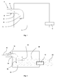
- the figure 1 shows a schematic of an exhaust gas duct component.
- the exhaust gas duct component shown in the figure forms a part of an exhaust gas channel.
- the exhaust gas channel may consist of a plurality of mufflers, plurality of pipes connecting the mufflers with each other and to the engine.
- the exhaust gas channel receives the exhaust gases from the engine and guides it to the outside of the vehicle.
- the mufflers in the exhaust gas channel reduce the noise created by the exhaust gases.
- the figure 1 shows only a part of an exhaust gas channel.
- the exhaust gas duct component shown in the Figure 1 comprises an input channel 10, an output channel 12 and a joining enclosure 14 which encloses a part of the input channel 10 and a part of the output channel 12.
- the joining enclosure 14 which may be a muffler has a bigger volume compared to the input channel 10 and the output channel 12.
- An electronic component 16 which needs to be protected from any liquid entering through the output channel 12, is placed in front or in the input channel 10 upstream of the exhaust gas duct component.
- the input channel 10 consists of a first part 20 and a second part 22, both parts joined together.
- the second part 22 is referred as stand pipe.
- Part of the first part 20 is inside the joining enclosure 14 and part of it is outside the joining enclosure 14.
- the stand pipe 22 is completely inside the joining enclosure 14.
- the input channel 10 is positioned in the joining enclosure 14 in such a way that the stand pipe 22 is pointing downwards and the opening part 24 of the stand pipe 22 is below the bottom wall 26 of the first part 20.
- the output channel 12 is placed closer to the bottom of the joining enclosure 14 and the input channel 10 is placed at a higher level compared the output channel 12, i.e. the first part 20 of the input channel 10 is at a conveniently higher level compared to the output channel 12.
- Figure 2 shows the functioning of the exhaust gas duct component when the vehicle enters an area filled with liquid, which may be water.
- the water enters the exhaust gas duct component through the output channel 12.
- the water entering the exhaust gas duct component will not immediately reach the electronic component 16 because the input channel 10 is at a higher position compared to the output channel 12. But if the water keeps entering through the output channel 12, the water level in the exhaust gas duct component keeps rising.
- the opening 24 of the stand pipe 22 of the input channel 10 is submerged in water.
- the water level in the input channel will not rise further because the exhaust gases shown with an arrow 30 entering the exhaust gas duct component through the input channel 10 will be at a higher pressure than the water rushing in through the output channel 12.
- the exhaust gases 30 entering the exhaust gas duct component will keep pushing down the water in the stand pipe 22 of the input channel 10 as shown with an arrow 32. This will result in a portion of the water to be pushed out of the exhaust gas duct component through the output channel 12.
- the height 18 represents the height of the waves the exhaust gas duct component will withstand before the electronic component 16 comes in contact with the water in the exhaust gas duct component.
- Figure 3 shows another embodiment of the invention.
- Figure 3 has all the components same as in Fig 1 except the shape of the input channel 10.
- Her the input channel has the first part 20 joined to the second part 22 with a pipe at an angle to both first part 20 and second part 22.
- the input channel 10 may have different shapes, consisting of a first part, a stand pipe slanting downwards at an angle, both parts joined together by a part which is convenient to be formed inside the joining enclosure.
Landscapes
- Engineering & Computer Science (AREA)
- Chemical & Material Sciences (AREA)
- Combustion & Propulsion (AREA)
- Mechanical Engineering (AREA)
- General Engineering & Computer Science (AREA)
- Exhaust Silencers (AREA)
Abstract
Description
- The invention relates to an exhaust gas duct component used to guide the exhaust gas emissions.
- There are different types of exhaust gas duct components available as state of the art.
- The disadvantage of the exhaust gas duct components known in the state of the art, is they are not capable of protecting any electronic component installed upstream in the exhaust gas channel, from contact with liquid possibly entering the exhaust gas channel when the vehicle is moving through water. When the water from outside enters the exhaust gas channel, the water may come into contact with any electronic component positioned in the exhaust gas channel. The water coming in contact with the electronic component placed in the exhaust gas channel may damage the electronic component.
- For example, a sensor positioned in the exhaust gas channel will be at a high temperature when the vehicle is running. When the sensor comes in contact with water the sensor will get damaged.
- The invention proposes an advantageous solution for the disadvantage encountered above.
- The device according to the independent patent claim has the below mentioned advantages:
- The exhaust gas duct component proposed in the invention has an input channel and an output channel. The input channel has two parts, a first part and a second part joined together with a non zero angle between them. The input channel is formed in such a way that the liquid possibly entering through the output channel will not reach easily an electronic component located upstream of exhaust gas duct component.
- Further improvements and/or advantages are realised by the features of the dependent patent claims.
- The exhaust gas duct component has a simple design not deviating much from the components available as state of the art.
- The output channel can be placed advantageously close to the bottom of the duct component so that any water collected in the duct component will flow out automatically when the water level outside is lower than the level of the output channel.
-
- Figure 1
- shows a schematic of an exhaust gas duct component according to a first embodiment
- Figure 2
- a schematic of an exhaust gas duct component when the vehicle is moving through water
- Figure 3
- shows a schematic of an exhaust gas duct component according to a second embodiment
- The
figure 1 shows a schematic of an exhaust gas duct component. The exhaust gas duct component shown in the figure forms a part of an exhaust gas channel. The exhaust gas channel may consist of a plurality of mufflers, plurality of pipes connecting the mufflers with each other and to the engine. The exhaust gas channel receives the exhaust gases from the engine and guides it to the outside of the vehicle. The mufflers in the exhaust gas channel reduce the noise created by the exhaust gases. Thefigure 1 shows only a part of an exhaust gas channel. - The exhaust gas duct component shown in the
Figure 1 comprises aninput channel 10, anoutput channel 12 and a joiningenclosure 14 which encloses a part of theinput channel 10 and a part of theoutput channel 12. The joiningenclosure 14 which may be a muffler has a bigger volume compared to theinput channel 10 and theoutput channel 12. - An
electronic component 16 which needs to be protected from any liquid entering through theoutput channel 12, is placed in front or in theinput channel 10 upstream of the exhaust gas duct component. - The
input channel 10 consists of afirst part 20 and asecond part 22, both parts joined together. Thesecond part 22 is referred as stand pipe. Part of thefirst part 20 is inside the joiningenclosure 14 and part of it is outside the joiningenclosure 14. Thestand pipe 22 is completely inside the joiningenclosure 14. - The
input channel 10 is positioned in the joiningenclosure 14 in such a way that thestand pipe 22 is pointing downwards and theopening part 24 of thestand pipe 22 is below thebottom wall 26 of thefirst part 20. - The
output channel 12 is placed closer to the bottom of the joiningenclosure 14 and theinput channel 10 is placed at a higher level compared theoutput channel 12, i.e. thefirst part 20 of theinput channel 10 is at a conveniently higher level compared to theoutput channel 12. -
Figure 2 shows the functioning of the exhaust gas duct component when the vehicle enters an area filled with liquid, which may be water. The water enters the exhaust gas duct component through theoutput channel 12. The water entering the exhaust gas duct component will not immediately reach theelectronic component 16 because theinput channel 10 is at a higher position compared to theoutput channel 12. But if the water keeps entering through theoutput channel 12, the water level in the exhaust gas duct component keeps rising. When the water level rises to alevel 34, the opening 24 of thestand pipe 22 of theinput channel 10 is submerged in water. Now the water level in the input channel will not rise further because the exhaust gases shown with an arrow 30 entering the exhaust gas duct component through theinput channel 10 will be at a higher pressure than the water rushing in through theoutput channel 12. The exhaust gases 30 entering the exhaust gas duct component will keep pushing down the water in thestand pipe 22 of theinput channel 10 as shown with anarrow 32. This will result in a portion of the water to be pushed out of the exhaust gas duct component through theoutput channel 12. - When the water is collected in the joining
enclosure 14 and when the vehicle is moving, the water will move in the form of waves inside the joiningenclosure 14. Theheight 18 represents the height of the waves the exhaust gas duct component will withstand before theelectronic component 16 comes in contact with the water in the exhaust gas duct component. - When the
water level 38 outside of the vehicle recedes below the level of theoutput channel 12, the water collected in the exhaust duct component will start flowing out of the exhaust gas duct component through theoutput channel 12. A little amount of water which may be still left in the exhaust gas duct component will evaporate because of the high temperature of the exhaust gases. -
Figure 3 shows another embodiment of the invention.Figure 3 has all the components same as inFig 1 except the shape of theinput channel 10. Her the input channel has thefirst part 20 joined to thesecond part 22 with a pipe at an angle to bothfirst part 20 andsecond part 22. - In different embodiments of the invention, the
input channel 10 may have different shapes, consisting of a first part, a stand pipe slanting downwards at an angle, both parts joined together by a part which is convenient to be formed inside the joining enclosure.
Claims (13)
- An Exhaust gas duct component for exhaust gas, comprising an input channel (10), an output channel (12) and a joining enclosure (14), which can be arranged in an exhaust gas duct, down stream of a liquid sensitive component (16), characterized in that,
the input channel (10) has a first part (20) and a second part (22) wherein the second part (22) is positioned inside the joining enclosure (14) and wherein the second part (22) has a direction with a non zero angle relative to the direction of the first part (20), so that a liquid possibly entering the joining enclosure ( 14 ) from the output channel ( 12 ) can be prevented from reaching the liquid sensitive component. (16). - An Exhaust gas duct component according to claim 1 wherein the joining enclosure (14) is a muffler.
- An Exhaust gas duct component according to claim 1 or 2 wherein the second part (22) of the input channel (10) is formed as a stand pipe and joined to the first part (20).
- An Exhaust gas duct component according to one of the preceding claims wherein the first part (20) of the input channel (10) is placed horizontally.
- An Exhaust gas duct component according to one of the preceding claims wherein the second part (22) is slanting downwards.
- An Exhaust gas duct component according to one of the preceding claims wherein the opening (24) of the second part (22) is at a level below a bottom wall (26) of the first part (20) of the input channel.
- An Exhaust gas duct component according to one of the preceding claims wherein the first part (20) is partly exposed out side the joining enclosure (14).
- An Exhaust gas duct component according to one of the preceding claims wherein the second part (22) has at least a minimum height (18) which can avoid waves of the liquid possibly created inside the joining enclosure (14) by movement of the vehicle, from reaching the first part (20).
- An Exhaust gas duct component according to one of the preceding claims wherein the output channel (12) is placed horizontally.
- An Exhaust gas duct component according to one of the preceding claims wherein at least the first part (20) of the input channel (10) is placed at a higher level relative to the output channel (12).
- An Exhaust gas duct component according to one of the preceding claims wherein the output channel (12) is placed close to the bottom of the joining enclosure (14) so that if any liquid is collected in the joining enclosure (14), the liquid will flow out through the output channel (12) when the level of the liquid outside of the exhaust duct component is lower than inside of the joining enclosure.
- An Exhaust gas duct component according to one of the preceding claims wherein the liquid sensitive component (16) is an electronic component, e.g. a sensor, especially an electrically heated sensor.
- An exhaust gas channel comprising a liquid sensitive component, e.g. an electronic component and an exhaust gas duct component according to one of the preceding claims arranged downstream of the liquid sensitive component.
Priority Applications (1)
| Application Number | Priority Date | Filing Date | Title |
|---|---|---|---|
| EP08102520A EP2101048A1 (en) | 2008-03-12 | 2008-03-12 | An exhaust gas duct component |
Applications Claiming Priority (1)
| Application Number | Priority Date | Filing Date | Title |
|---|---|---|---|
| EP08102520A EP2101048A1 (en) | 2008-03-12 | 2008-03-12 | An exhaust gas duct component |
Publications (1)
| Publication Number | Publication Date |
|---|---|
| EP2101048A1 true EP2101048A1 (en) | 2009-09-16 |
Family
ID=39674832
Family Applications (1)
| Application Number | Title | Priority Date | Filing Date |
|---|---|---|---|
| EP08102520A Withdrawn EP2101048A1 (en) | 2008-03-12 | 2008-03-12 | An exhaust gas duct component |
Country Status (1)
| Country | Link |
|---|---|
| EP (1) | EP2101048A1 (en) |
Citations (3)
| Publication number | Priority date | Publication date | Assignee | Title |
|---|---|---|---|---|
| US1065707A (en) * | 1913-06-24 | Nicholas W Montgomery | Under-water exhaust for explosive and other engines. | |
| US2498979A (en) * | 1943-09-18 | 1950-02-28 | Maxim Silencer Co | Water separator silencer |
| US4184566A (en) * | 1978-05-10 | 1980-01-22 | Maritec Corporation | Marine engine noise suppressor |
-
2008
- 2008-03-12 EP EP08102520A patent/EP2101048A1/en not_active Withdrawn
Patent Citations (3)
| Publication number | Priority date | Publication date | Assignee | Title |
|---|---|---|---|---|
| US1065707A (en) * | 1913-06-24 | Nicholas W Montgomery | Under-water exhaust for explosive and other engines. | |
| US2498979A (en) * | 1943-09-18 | 1950-02-28 | Maxim Silencer Co | Water separator silencer |
| US4184566A (en) * | 1978-05-10 | 1980-01-22 | Maritec Corporation | Marine engine noise suppressor |
Similar Documents
| Publication | Publication Date | Title |
|---|---|---|
| EP2107349B1 (en) | Air flow measuring device | |
| JP5440271B2 (en) | Intake manifold for vehicles | |
| EP1939415A1 (en) | Exhaust system | |
| CN103608576B (en) | EGR device for internal combustion engine | |
| CN105697111B (en) | For determining the sensor device of the delivery temperature of explosive motor | |
| JP5779471B2 (en) | Humidity detector | |
| CN204851408U (en) | Indulge and put engine close coupling exhaust manifold subassembly | |
| EP2101048A1 (en) | An exhaust gas duct component | |
| JP6047974B2 (en) | Gas sensor protective cover structure | |
| CN105909353A (en) | Exhaust gas system for a combustion engine | |
| JP2017214907A (en) | Urea water addition system for internal combustion engine | |
| JP5999324B2 (en) | Intake system structure of internal combustion engine | |
| JP5604348B2 (en) | Diesel engine exhaust treatment equipment | |
| JP2014088822A (en) | Engine heat shield structure | |
| JP2013053593A (en) | Device for preventing water splash of gas sensor | |
| JP6201740B2 (en) | Drainage device for internal combustion engine | |
| JP7803265B2 (en) | connecting pipe | |
| JP6187243B2 (en) | Drainage device for internal combustion engine | |
| KR100501372B1 (en) | Gas flux structure of exhaust system in vehicle | |
| RU2004107013A (en) | GAS-TRANSFER UNIT WITH GAS-TURBINE ENGINE | |
| JP2022129255A (en) | Pipe | |
| CN105986874B (en) | Heat insulating device for vehicle exhaust gas purification system | |
| CN203742739U (en) | Noise abatement device | |
| JP2014051943A (en) | Exhaust gas recirculating device of engine | |
| CN101377146A (en) | Silencer for automobile |
Legal Events
| Date | Code | Title | Description |
|---|---|---|---|
| PUAI | Public reference made under article 153(3) epc to a published international application that has entered the european phase |
Free format text: ORIGINAL CODE: 0009012 |
|
| AK | Designated contracting states |
Kind code of ref document: A1 Designated state(s): AT BE BG CH CY CZ DE DK EE ES FI FR GB GR HR HU IE IS IT LI LT LU LV MC MT NL NO PL PT RO SE SI SK TR |
|
| AX | Request for extension of the european patent |
Extension state: AL BA MK RS |
|
| 17P | Request for examination filed |
Effective date: 20100316 |
|
| 17Q | First examination report despatched |
Effective date: 20100422 |
|
| AKX | Designation fees paid |
Designated state(s): AT BE BG CH CY CZ DE DK EE ES FI FR GB GR HR HU IE IS IT LI LT LU LV MC MT NL NO PL PT RO SE SI SK TR |
|
| STAA | Information on the status of an ep patent application or granted ep patent |
Free format text: STATUS: THE APPLICATION IS DEEMED TO BE WITHDRAWN |
|
| 18D | Application deemed to be withdrawn |
Effective date: 20101110 |