EP2101007A1 - An insulating wall system for a building structure - Google Patents
An insulating wall system for a building structure Download PDFInfo
- Publication number
- EP2101007A1 EP2101007A1 EP08102444A EP08102444A EP2101007A1 EP 2101007 A1 EP2101007 A1 EP 2101007A1 EP 08102444 A EP08102444 A EP 08102444A EP 08102444 A EP08102444 A EP 08102444A EP 2101007 A1 EP2101007 A1 EP 2101007A1
- Authority
- EP
- European Patent Office
- Prior art keywords
- profile
- protrusions
- mounting
- profiles
- wall system
- Prior art date
- Legal status (The legal status is an assumption and is not a legal conclusion. Google has not performed a legal analysis and makes no representation as to the accuracy of the status listed.)
- Withdrawn
Links
- 238000009413 insulation Methods 0.000 claims abstract description 33
- 238000000034 method Methods 0.000 claims abstract description 16
- 239000012774 insulation material Substances 0.000 claims abstract description 11
- 230000014759 maintenance of location Effects 0.000 claims abstract description 5
- 239000000463 material Substances 0.000 claims description 9
- -1 polyethylene Polymers 0.000 claims description 5
- 239000004033 plastic Substances 0.000 claims description 4
- 229920003023 plastic Polymers 0.000 claims description 4
- 239000004698 Polyethylene Substances 0.000 claims description 3
- 229920000573 polyethylene Polymers 0.000 claims description 3
- 239000004743 Polypropylene Substances 0.000 claims description 2
- 239000007769 metal material Substances 0.000 claims description 2
- 229920001155 polypropylene Polymers 0.000 claims description 2
- 229920000915 polyvinyl chloride Polymers 0.000 claims description 2
- 239000004800 polyvinyl chloride Substances 0.000 claims description 2
- 229910000831 Steel Inorganic materials 0.000 description 8
- 239000010959 steel Substances 0.000 description 8
- 239000002184 metal Substances 0.000 description 2
- 238000010521 absorption reaction Methods 0.000 description 1
- 238000005452 bending Methods 0.000 description 1
- 230000008602 contraction Effects 0.000 description 1
- 238000006073 displacement reaction Methods 0.000 description 1
- 238000009826 distribution Methods 0.000 description 1
- 238000004049 embossing Methods 0.000 description 1
- 230000002708 enhancing effect Effects 0.000 description 1
- 238000001746 injection moulding Methods 0.000 description 1
- 238000004519 manufacturing process Methods 0.000 description 1
- 230000000284 resting effect Effects 0.000 description 1
- 230000001932 seasonal effect Effects 0.000 description 1
- 238000000638 solvent extraction Methods 0.000 description 1
- 239000010935 stainless steel Substances 0.000 description 1
Images


Classifications
-
- E—FIXED CONSTRUCTIONS
- E04—BUILDING
- E04B—GENERAL BUILDING CONSTRUCTIONS; WALLS, e.g. PARTITIONS; ROOFS; FLOORS; CEILINGS; INSULATION OR OTHER PROTECTION OF BUILDINGS
- E04B1/00—Constructions in general; Structures which are not restricted either to walls, e.g. partitions, or floors or ceilings or roofs
- E04B1/62—Insulation or other protection; Elements or use of specified material therefor
- E04B1/74—Heat, sound or noise insulation, absorption, or reflection; Other building methods affording favourable thermal or acoustical conditions, e.g. accumulating of heat within walls
- E04B1/76—Heat, sound or noise insulation, absorption, or reflection; Other building methods affording favourable thermal or acoustical conditions, e.g. accumulating of heat within walls specifically with respect to heat only
Definitions
- the present invention relates to the field of an insulating wall system for a building structure, wherein said wall system comprises a first wall with insulation material attached to said first wall by a plurality of mounting profiles and fastening members extending through the mounting profiles and the insulation.
- the mounting profiles are preferably made of steel, such as galvanised steel, to ensure a low-cost and weather-resistant profile to hold the insulation in place.
- the mounting profiles are produced in certain lengths. When the profiles are mounted, the fasteners may bend in order to absorb the thermal expansion or contraction in the profiles.
- two or more mounting profiles may be mounted in continuation of each other in order to support the insulation throughout the entire façade. Accordingly, the profiles abut each other. Thermal expansion of the profiles in this configuration might result in a displacement of the profiles and consequently a potentially disastrous loss of friction in the genius insulating wall system described above, where the insulation is held in place due to the friction created between the first wall and the insulation and the insulation and the mounting profiles as the fasteners are mounted with a pre-stressed tension slightly compressing the insulation material.
- An object of the invention may be to provide an insulating wall system for a building structure where thermal expansions of the profiles in the wall system are absorbed so that the risk of disfiguration of the wall system or even the failure of the wall system is prevented.
- an insulating wall system for a building structure comprising a first wall with insulation material attached to said first wall by a plurality of mounting profiles and fastening members extending through the mounting profiles and the insulation, wherein two or more mounting profiles are mounted in continuation of each other, and wherein an intermediate profile distance member for facilitating mounting and retention of two adjacent mounting profiles, said member comprising a base portion with one or more first protrusions on one side and one or more second protrusions on the other side, wherein the one or more first protrusions are adapted to engage the end of a first profile and the one or more second protrusions are adapted to engage the end of a second profile mounted in continuation of the first profile.
- a method of mounting an insulating wall system on a building structure comprising the steps of providing a first wall, attaching insulation material to said first wall by a plurality of mounting profiles and fastening members extending through the mounting profiles and the insulation, wherein two or more mounting profiles are mounted one after another in continuation of each other, whereby a first mounting profile is mounted, mounting an intermediate profile distance member having a base portion with one or more first protrusions on one side and one or more second protrusions on the other side, so that the one or more first protrusions engage the end of a first profile, and mounting a second profile in continuation of the first profile by fitting the end of said second profile over the one or more second protrusions on said distance member adapted for this purpose.
- a method of absorbing thermal expansions of mounting profiles in a building structure using at least one intermediate profile distance member for facilitating mounting of two mounting profiles in a wall system of a building structure said member comprising a base portion with one or more first protrusions on one side and one or more second protrusions on the other side, wherein the one or more first protrusions are adapted to engage the end of a first profile and the one or more second protrusions are adapted to engage the end of a second profile mounted in continuation of the first profile.
- the thermal expansion is absorbed in a manner so that the profiles are not mutually displaced.
- the profiles may slide along the associated protrusions in order to compensate for the thermal conditions the wall system is exposed to. It is common to produce such profiles in a metal, such as steel. With steel expanding approx. 1 mm per meter when heated approx. 60°C, building structures, in particular when situated on the outside of the thermal insulation, is exposed to considerable thermal variations due to sunlight, seasonal climate changes, etc..
- a method and a system and an associated intermediate distance member so that these thermal expansions may be absorbed without risking thermal deformation of the profiles whereby the insulation mounting could otherwise become loose and the wall structure thereby be jeopardised.
- the distance member is made of a non-metallic material, preferably a plastic material, more preferably a material selected from polyethylene, polypropylene, polyvinylchloride, or any combination thereof. Moreover, the distance member is preferably integrally formed in a single piece.
- the first protrusions comprise two protrusions provided at the two distal regions of the base portion and said first protrusions are adapted to engage into said first profile by extending into openings in the end of said first profile.
- the second protrusions preferably comprise two protrusions provided at the two distal regions of the base portion and wherein the said second protrusions are adapted to engage into said second profile by extending into openings in the end of said second profile.
- an elevated portion between the two second protrusions, where said elevated portion extends out of the plane of the base portion, preferably at the second side of the base portion and with an extension distance less than said second protrusions.
- the elevated portion serves the function of facilitating the positioning of the second profile and is preferably provided with a sloping surface of at least the distal portion of the elevated portion, most preferably at the longitudinal side of the base portion facing towards the side where the inner surfaces of the one or more second protrusions are spaced most apart, i.e. where the surfaces are "pointing outwards".
- said elevated portion comprises one or more distance fins provided for abutment by the end of the central engagement portion of the profile and wherein said fins are adapted for collapsing if exerted to a pressure exceeding a predetermined amount by the second profile once said profile is mounted.
- These collapsible fins are preferably provided at the longitudinal side of the base portion where the inner surfaces are "pointing inwards, i.e. opposite the sloping surface of the elevated portion, if such sloping surface is provided thereon.
- the mounting profiles are provided with a central insulation engagement portion and two building cover structure receiving surfaces on each side of said central insulation engagement portion and with inclined intermediate portions therebetween.
- the first and second sets of protrusions are provided with inwardly facing surfaces provided with an inclination corresponding to the inclined intermediate portions of the profiles. These inclinations are such that the profile is guided into the correct position.
- the distance member is symmetrical at least about a centre plane so that the first and second protrusions on either side of said plane are symmetrically identical.
- the one or more first protrusions may in a preferred embodiment be formed with a cross-sectional foursided trapezoid shape where the two outermost angles are perpendicular and all sides except the innermost side are substantially parallel with the outer contour of the base portion.
- the corresponding outer region of the profile generally circumscribes this geometric shape of the first protrusions so that the distance member is firmly fitted into the end portion of the first profile.
- the second protrusions may be provided with an inner surface and one or two supporting flanges as no further surfaces are considered required in a preferred embodiment in order to receive and guide the end of the second profile into position.
- a first wall 1 is provided, said first wall preferably being an inner wall.
- slabs of fibrous insulation 2 are provided, and this insulation material 2 is mounted by a number of support profiles 3, which are secured to the wall 1 by fasteners pierced through the insulation 2 and mounted with a predetermined amount of tension thereby slightly compressing the insulation 2 and establishing a frictional force between the wall 1 and the insulation 2 and between the insulation 2 and the profiles 3.
- the profiles 3 are moreover designed for supporting the outer skin of the building, i.e. the outer wall structure, i.e. a second wall (not shown in the figures).
- the profiles 3 may also be provided in continuation of each other, as shown in the figures with the profiles 3' and 3".
- a metal profile 3 is provided as mounting profile 3 in the wall system.
- This profile 3 is advantageous as it is inexpensive in manufacture and of a fire-proof material, such as steel, preferably corrosion-resistant steel, galvanised steel or the like.
- the profile 3 is formed with a central insulation engagement portion 31 and two building cover structure receiving surfaces 32 on each side of the central portion 31.
- the building cover receiving surfaces 32 are formed in a plane parallel with the central insulation engagement portion 31 and as shown in fig. 3 connecting portions 33 are formed which are formed as a bend in the sheet material with respect to the central portion 31, which provides extra stiffness to the profile 3.
- outer portions are formed which are substantially perpendicular to the building cover receiving surfaces 32.
- the particular cross-sectional shape of the profile 3, as shown in fig. 3 provides the profile 3 with a stiffness that ensures an even distribution of the friction forces when the profile 3 is mounted in the wall system sandwiching the insulation material 2 between the profile 3 and the first wall 1.
- the profile 3 is formed with a specific shape providing sufficient stiffness so that the profile 3 does not bend substantially along its longitudinal axis when fitted by pre-stressed fasteners 5.
- mounting holes and friction enhancing knobs such as an array of rearwardly extending embossings.
- the profiles Due to changes in temperature, the profiles expand.
- the fasteners may absorb this expansion by bending.
- two profiles mounted in continuation of each other do not have sufficient space to expand.
- the profiles are in accordance with the present invention mounted with an intermediate distance member 4 between two neighbouring profiles 3', 3". This assembly is also shown in fig. 10 .
- the distance member 4 is preferably made in softer material relative to the material of the profiles 3', 3".
- the profiles 3 are made of steel, such as galvanised steel, and the distance member 4 is made of plastic.
- the distance member 4 is described in detail with reference to the figures 4 to 9 .
- the distance member 4 is formed integrally, preferably in a plastic material, such as polyethylene or the like, by injection moulding or the like.
- the distance member 4 is formed with a base portion 8 which is plate-like with a shape and size generally circumscribing the end section shape of the profiles 3.
- the distance member 4 is provided with two first protrusions 6 extending downwards and two second protrusions 7 facing upwards. These protrusions 6, 7 are adapted to slide into the end of the profile 3 for guidance. Accordingly, the first protrusions 6 are pointing downwards and formed with two symmetrically shaped protrusions 6 with an essentially trapezoid shape having an inclined inner surface 61 (see figs. 8 and 9 ). The end of the profile side portions 32, 33, 34 generally circumscribe the first protrusions 6.
- the first protrusions 6 are adapted to a precise fit inside the ends of the two side portions 32, 33, 34 of the profile 3 so that the inclined inner surface 61 of the first protrusions 6 are provided with a corresponding, such as the same or substantially similar, angular inclination as the connecting portion 33 of the profile 3.
- the distance member 4 can be easily fitted on the end of the first profile 3' already mounted on the wall system.
- the distance member may be fitted on the end of the first profile 3' before it is mounted on the wall.
- the distance member 4 is furthermore provided with two second protrusions 7 extending in the opposite direction of the first protrusions 6.
- These protrusions 7 are preferably shaped similar to the inner section only of the first protrusions 6, i.e. having with an inclined portion with an inner surface 71 (see figs. 8 and 9 ) adapted to cooperate with the correspondingly inclined connecting portions 33 of the profile 3, so that the second profile 3" can be easily fitted with its end around these two second protrusions 7.
- an elevated portion 9 Centrally on the base portion 8, there is an elevated portion 9 which is provided with a sloping surface 11 on the front side of the distance member 4 where the second profile 3" is received when it is being mounted.
- the end of the central engagement portion 31 of the second profile 3" may abut these collapsible fins 10 when the profile is mounted, but such abutment is not needed once the profiles are mounted the distance member has ensured that the profiles 3' and 3" are mounted in the wall system with a suitable distance apart to absorb thermal expansion. Since the distance member remains between the two profiles, the thermal expansion may be absorbed by the fins 10 which simply collapse when the profiles expand.
- the mounting process for the distance member 4 may be described as follows:
- the insulation material 2 is attached to the wall 1 by the first mounting profile 3' by fastening members 5 extending through the first profile 3' and the insulation 2 in a wall structure where two or more mounting profiles are to be mounted one after another in continuation of each other.
- the insulation material is somewhat compressed.
- the intermediate profile distance member 4 is fitted on the end of the first profile 3' with the first protrusions 6 extending into the retention portions 33 of the profile 3', whereas the second protrusions 7 extend upwards and ready to receive the next profile 3".
- the second profile 3" is mounted in continuation of the first profile 3' by fitting the end of said second profile 3" over the second protrusions 7 on said distance member 4. Since the second protrusions 7 are shaped like the "inner-half" of the first protrusion 6, there is no obstacle for the profile 3" to be pushed into place. As the profile end with the central portion 31 and the inclined connecting portions 33 on either side thereof is laid on the insulation the profile end is guided in place by the sloping surface 11 of elevated portion 9 of the distance member 4 and the correspondingly angled inner surfaces 71 on the second protrusions 7 and the connecting portions 33 on the profile facilitate a correct mounting as the profile end is wedged into alignment with the first profile 3'.
- the end of the central portion 31 may be guided by the sloping surface 11 to rest on the elevated portion 9 of the distance member 4 during mounting. This facilitates the fitting of the second profile 3".
- the profile 3" is positioned with its central portion 31 resting on the elevated portion 9, the profile 3" is mounted to the wall by a number of fasteners 5 whereby profile 3" slides in the direction of the arrow M and the insulation is compressed until the two profiles 3' and 3" becomes aligned, as shown in fig. 12 .
- the fins 10 are provided in this rear section 12 so that it is ensured that the second profile 3" does not slide or fall into this "groove” 12 and ensures that there is a distance between the profiles 3', 3" in order to absorb thermal expansion of the profiles later on.
- the distance member 4 When the profiles 3', 3" are mounted the distance member 4 effectively becomes superfluous since the profiles 3', 3" are firmly mounted with a distance between them due to the presence of the distance member during the mounting process. However, in order not to counteract any thermal expansion of the profiles, the distance member 4 is provided with the collapsible fins 10 so that any expansion breaks away these fins 10.
- the profiles are described as having openings. It is realised that the profiles shown in the figures are “open” profiles and not closed “tubular”-like profiles. However, by the term openings in relation to the profiles are meant any cavity which is accessible from the outside, in particular the end of the profiles.
- the invention is described with reference to a vertical side wall structure.
- wall structures may be provided with thermal absorption means according to the present invention. Examples thereof could be a roof structure.
- the wall system may also be used for internal walls in a building structure, where a partitioning wall must be provided with thermal insulation. Accordingly, it is realised that other variants than the above-described may be provided without departing from the scope of the invention as it is defined by the claims.
Landscapes
- Physics & Mathematics (AREA)
- Engineering & Computer Science (AREA)
- Architecture (AREA)
- Acoustics & Sound (AREA)
- Electromagnetism (AREA)
- Civil Engineering (AREA)
- Structural Engineering (AREA)
- Building Environments (AREA)
Abstract
The present invention concerns an insulating wall system for a building structure, wherein said wall system comprises a first wall (1) with insulation material (2) attached to said first wall by a plurality of mounting profiles (3) and fastening members (5) extending through the mounting profiles and the insulation, wherein two or more mounting profiles are mounted in continuation of each other, and wherein an intermediate profile distance member (4) for facilitating mounting and retention of two adjacent mounting profiles, said member comprising a base portion (8) with one or more first protrusions (6) on one side and one or more second protrusions (7) on the other side, wherein the one or more first protrusions are adapted to engage the end of a first profile and the one or more second protrusions are adapted to engage the end of a second profile mounted in continuation of the first profile. By the invention there is provided a method and a system and an associated intermediate distance member so that these thermal expansions may be absorbed without risking thermal deformation of the profiles and that the insulation mounting thereby could become loose and the wall structure thereby be jeopardised.
Description
- The present invention relates to the field of an insulating wall system for a building structure, wherein said wall system comprises a first wall with insulation material attached to said first wall by a plurality of mounting profiles and fastening members extending through the mounting profiles and the insulation.
- A wall system of such kind is known from
WO 2007/110244 , which is hereby incorporated by reference. The mounting profiles are preferably made of steel, such as galvanised steel, to ensure a low-cost and weather-resistant profile to hold the insulation in place. The mounting profiles are produced in certain lengths. When the profiles are mounted, the fasteners may bend in order to absorb the thermal expansion or contraction in the profiles. - However, in larger building structures two or more mounting profiles may be mounted in continuation of each other in order to support the insulation throughout the entire façade. Accordingly, the profiles abut each other. Thermal expansion of the profiles in this configuration might result in a displacement of the profiles and consequently a potentially disastrous loss of friction in the genius insulating wall system described above, where the insulation is held in place due to the friction created between the first wall and the insulation and the insulation and the mounting profiles as the fasteners are mounted with a pre-stressed tension slightly compressing the insulation material.
- An object of the invention may be to provide an insulating wall system for a building structure where thermal expansions of the profiles in the wall system are absorbed so that the risk of disfiguration of the wall system or even the failure of the wall system is prevented.
- According to the invention, there is provided an insulating wall system for a building structure, wherein said wall system comprises a first wall with insulation material attached to said first wall by a plurality of mounting profiles and fastening members extending through the mounting profiles and the insulation, wherein two or more mounting profiles are mounted in continuation of each other, and wherein an intermediate profile distance member for facilitating mounting and retention of two adjacent mounting profiles, said member comprising a base portion with one or more first protrusions on one side and one or more second protrusions on the other side, wherein the one or more first protrusions are adapted to engage the end of a first profile and the one or more second protrusions are adapted to engage the end of a second profile mounted in continuation of the first profile.
- In a second aspect of the invention, there is provided a method of mounting an insulating wall system on a building structure, said method comprising the steps of providing a first wall, attaching insulation material to said first wall by a plurality of mounting profiles and fastening members extending through the mounting profiles and the insulation, wherein two or more mounting profiles are mounted one after another in continuation of each other, whereby a first mounting profile is mounted, mounting an intermediate profile distance member having a base portion with one or more first protrusions on one side and one or more second protrusions on the other side, so that the one or more first protrusions engage the end of a first profile, and mounting a second profile in continuation of the first profile by fitting the end of said second profile over the one or more second protrusions on said distance member adapted for this purpose.
- Furthermore, in a third aspect of the invention, there is provided a method of absorbing thermal expansions of mounting profiles in a building structure using at least one intermediate profile distance member for facilitating mounting of two mounting profiles in a wall system of a building structure, said member comprising a base portion with one or more first protrusions on one side and one or more second protrusions on the other side, wherein the one or more first protrusions are adapted to engage the end of a first profile and the one or more second protrusions are adapted to engage the end of a second profile mounted in continuation of the first profile.
- By providing a distance member between the profiles in the wall system, the thermal expansion is absorbed in a manner so that the profiles are not mutually displaced. The profiles may slide along the associated protrusions in order to compensate for the thermal conditions the wall system is exposed to. It is common to produce such profiles in a metal, such as steel. With steel expanding approx. 1 mm per meter when heated approx. 60°C, building structures, in particular when situated on the outside of the thermal insulation, is exposed to considerable thermal variations due to sunlight, seasonal climate changes, etc.. By the invention there is provided a method and a system and an associated intermediate distance member so that these thermal expansions may be absorbed without risking thermal deformation of the profiles whereby the insulation mounting could otherwise become loose and the wall structure thereby be jeopardised.
- In a preferred embodiment of the invention, the distance member is made of a non-metallic material, preferably a plastic material, more preferably a material selected from polyethylene, polypropylene, polyvinylchloride, or any combination thereof. Moreover, the distance member is preferably integrally formed in a single piece.
- In the preferred embodiment of the invention, the first protrusions comprise two protrusions provided at the two distal regions of the base portion and said first protrusions are adapted to engage into said first profile by extending into openings in the end of said first profile. Similarly, the second protrusions preferably comprise two protrusions provided at the two distal regions of the base portion and wherein the said second protrusions are adapted to engage into said second profile by extending into openings in the end of said second profile. As the protrusions substantially extend with the orientation substantially parallel to the longitudinal direction of the profiles, the thermal elongation of the profile will cause each of the profiles to slide on their associated set of guide protrusions on the distance member.
- In a preferred embodiment of the invention, there is provided an elevated portion between the two second protrusions, where said elevated portion extends out of the plane of the base portion, preferably at the second side of the base portion and with an extension distance less than said second protrusions. The elevated portion serves the function of facilitating the positioning of the second profile and is preferably provided with a sloping surface of at least the distal portion of the elevated portion, most preferably at the longitudinal side of the base portion facing towards the side where the inner surfaces of the one or more second protrusions are spaced most apart, i.e. where the surfaces are "pointing outwards".
- In a further embodiment, said elevated portion comprises one or more distance fins provided for abutment by the end of the central engagement portion of the profile and wherein said fins are adapted for collapsing if exerted to a pressure exceeding a predetermined amount by the second profile once said profile is mounted. These collapsible fins are preferably provided at the longitudinal side of the base portion where the inner surfaces are "pointing inwards, i.e. opposite the sloping surface of the elevated portion, if such sloping surface is provided thereon.
- In the preferred embodiment of the invention, the mounting profiles are provided with a central insulation engagement portion and two building cover structure receiving surfaces on each side of said central insulation engagement portion and with inclined intermediate portions therebetween. Correspondingly, the first and second sets of protrusions are provided with inwardly facing surfaces provided with an inclination corresponding to the inclined intermediate portions of the profiles. These inclinations are such that the profile is guided into the correct position.
- Preferably, the distance member is symmetrical at least about a centre plane so that the first and second protrusions on either side of said plane are symmetrically identical. The one or more first protrusions may in a preferred embodiment be formed with a cross-sectional foursided trapezoid shape where the two outermost angles are perpendicular and all sides except the innermost side are substantially parallel with the outer contour of the base portion. The corresponding outer region of the profile generally circumscribes this geometric shape of the first protrusions so that the distance member is firmly fitted into the end portion of the first profile. The second protrusions may be provided with an inner surface and one or two supporting flanges as no further surfaces are considered required in a preferred embodiment in order to receive and guide the end of the second profile into position.
- In the following, the invention is described in more detail with reference to the accompanying drawings, in which:
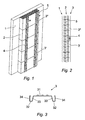
- fig. 1
- is a schematic perspective view of an insulating wall system according to the invention;
- fig. 2
- is a schematic cross-section side view of the insulating wall system,
- fig. 3
- is a cross-section view of a mounting profile for use in an insulating wall system according to the invention;
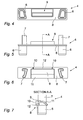
- fig. 4
- is a bottom view of a distance member according to a preferred embodiment of the invention;
- fig. 5
- is a side view of this distance member according to a preferred embodiment of the invention;
- fig. 6 is
- a top view of a distance member according to a preferred embodiment of the invention;
- fig. 7
- is a cross-section side view of the section A-A of
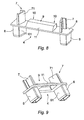
fig. 5 ; - fig. 8
- is a perspective view of a preferred embodiment of a distance member according to the invention;
- fig. 9
- is another perspective view thereof; and
- fig. 10
- is a schematic perspective view of an assembly of two mounting profiles with a distance member according to the invention, and
- figures 11 and 12
- are schematic longitudinal cross-section views illustrating the mounting process of a wall system according to the invention.
- With reference to
figures 1 and 2 , an embodiment of the wall system according to the invention is shown. Afirst wall 1 is provided, said first wall preferably being an inner wall. On the outside surface of thisinner wall 1, slabs offibrous insulation 2 are provided, and thisinsulation material 2 is mounted by a number ofsupport profiles 3, which are secured to thewall 1 by fasteners pierced through theinsulation 2 and mounted with a predetermined amount of tension thereby slightly compressing theinsulation 2 and establishing a frictional force between thewall 1 and theinsulation 2 and between theinsulation 2 and theprofiles 3. Theprofiles 3 are moreover designed for supporting the outer skin of the building, i.e. the outer wall structure, i.e. a second wall (not shown in the figures). Besides parallelly mountedprofiles 3, in particular on larger areas on a building structure, theprofiles 3 may also be provided in continuation of each other, as shown in the figures with theprofiles 3' and 3". - Preferably, a
metal profile 3 is provided asmounting profile 3 in the wall system. Thisprofile 3 is advantageous as it is inexpensive in manufacture and of a fire-proof material, such as steel, preferably corrosion-resistant steel, galvanised steel or the like. Theprofile 3 is formed with a centralinsulation engagement portion 31 and two building cover structure receivingsurfaces 32 on each side of thecentral portion 31. The buildingcover receiving surfaces 32 are formed in a plane parallel with the centralinsulation engagement portion 31 and as shown infig. 3 connectingportions 33 are formed which are formed as a bend in the sheet material with respect to thecentral portion 31, which provides extra stiffness to theprofile 3. On the outside of the buildingcover receiving surfaces 32 outer portions are formed which are substantially perpendicular to the building cover receiving surfaces 32. The particular cross-sectional shape of theprofile 3, as shown infig. 3 , provides theprofile 3 with a stiffness that ensures an even distribution of the friction forces when theprofile 3 is mounted in the wall system sandwiching theinsulation material 2 between theprofile 3 and thefirst wall 1. Theprofile 3 is formed with a specific shape providing sufficient stiffness so that theprofile 3 does not bend substantially along its longitudinal axis when fitted bypre-stressed fasteners 5. In thecentral portion 31 of theprofile 3 there is provided mounting holes and friction enhancing knobs such as an array of rearwardly extending embossings. By theprofile 3, a uniform contact between theprofile 3 and theinsulation 2 may be established. - Due to changes in temperature, the profiles expand. The fasteners may absorb this expansion by bending. However, two profiles mounted in continuation of each other do not have sufficient space to expand. To address this problem, the profiles are in accordance with the present invention mounted with an
intermediate distance member 4 between twoneighbouring profiles 3', 3". This assembly is also shown infig. 10 . Thedistance member 4 is preferably made in softer material relative to the material of theprofiles 3', 3". In the preferred embodiment, theprofiles 3 are made of steel, such as galvanised steel, and thedistance member 4 is made of plastic. - The
distance member 4 is described in detail with reference to thefigures 4 to 9 . In a preferred embodiment, thedistance member 4 is formed integrally, preferably in a plastic material, such as polyethylene or the like, by injection moulding or the like. Thedistance member 4 is formed with abase portion 8 which is plate-like with a shape and size generally circumscribing the end section shape of theprofiles 3. - The
distance member 4 is provided with twofirst protrusions 6 extending downwards and twosecond protrusions 7 facing upwards. Theseprotrusions profile 3 for guidance. Accordingly, thefirst protrusions 6 are pointing downwards and formed with two symmetrically shapedprotrusions 6 with an essentially trapezoid shape having an inclined inner surface 61 (seefigs. 8 and 9 ). The end of theprofile side portions first protrusions 6. This means that thefirst protrusions 6 are adapted to a precise fit inside the ends of the twoside portions profile 3 so that the inclinedinner surface 61 of thefirst protrusions 6 are provided with a corresponding, such as the same or substantially similar, angular inclination as the connectingportion 33 of theprofile 3. In this manner thedistance member 4 can be easily fitted on the end of the first profile 3' already mounted on the wall system. Alternatively, the distance member may be fitted on the end of the first profile 3' before it is mounted on the wall. - The
distance member 4 is furthermore provided with twosecond protrusions 7 extending in the opposite direction of thefirst protrusions 6. Theseprotrusions 7 are preferably shaped similar to the inner section only of thefirst protrusions 6, i.e. having with an inclined portion with an inner surface 71 (seefigs. 8 and 9 ) adapted to cooperate with the correspondingly inclined connectingportions 33 of theprofile 3, so that thesecond profile 3" can be easily fitted with its end around these twosecond protrusions 7. - Centrally on the
base portion 8, there is anelevated portion 9 which is provided with a slopingsurface 11 on the front side of thedistance member 4 where thesecond profile 3" is received when it is being mounted. On the other side of theelevated portion 9, i.e. the side facing towards theinsulation 2 when thedistance member 4 is mounted between theprofiles 3, one or morecollapsible fins 10 are provided in arear section 12 of thebase portion 8 behind theelevated portion 9. The end of thecentral engagement portion 31 of thesecond profile 3" may abut thesecollapsible fins 10 when the profile is mounted, but such abutment is not needed once the profiles are mounted the distance member has ensured that theprofiles 3' and 3" are mounted in the wall system with a suitable distance apart to absorb thermal expansion. Since the distance member remains between the two profiles, the thermal expansion may be absorbed by thefins 10 which simply collapse when the profiles expand. - With reference to
figures 11 to 12 , the mounting process for thedistance member 4 may be described as follows: - The
insulation material 2 is attached to thewall 1 by the first mounting profile 3' byfastening members 5 extending through the first profile 3' and theinsulation 2 in a wall structure where two or more mounting profiles are to be mounted one after another in continuation of each other. When the first profile 3' is mounted, the insulation material is somewhat compressed. The intermediateprofile distance member 4 is fitted on the end of the first profile 3' with thefirst protrusions 6 extending into theretention portions 33 of the profile 3', whereas thesecond protrusions 7 extend upwards and ready to receive thenext profile 3". - The
second profile 3" is mounted in continuation of the first profile 3' by fitting the end of saidsecond profile 3" over thesecond protrusions 7 on saiddistance member 4. Since thesecond protrusions 7 are shaped like the "inner-half" of thefirst protrusion 6, there is no obstacle for theprofile 3" to be pushed into place. As the profile end with thecentral portion 31 and the inclined connectingportions 33 on either side thereof is laid on the insulation the profile end is guided in place by the slopingsurface 11 ofelevated portion 9 of thedistance member 4 and the correspondingly angledinner surfaces 71 on thesecond protrusions 7 and the connectingportions 33 on the profile facilitate a correct mounting as the profile end is wedged into alignment with the first profile 3'. - The end of the
central portion 31 may be guided by the slopingsurface 11 to rest on theelevated portion 9 of thedistance member 4 during mounting. This facilitates the fitting of thesecond profile 3". When theprofile 3" is positioned with itscentral portion 31 resting on theelevated portion 9, theprofile 3" is mounted to the wall by a number offasteners 5 wherebyprofile 3" slides in the direction of the arrow M and the insulation is compressed until the twoprofiles 3' and 3" becomes aligned, as shown infig. 12 . In order to ensure that thesecond profile 3" does not fall into therear section 12, thefins 10 are provided in thisrear section 12 so that it is ensured that thesecond profile 3" does not slide or fall into this "groove" 12 and ensures that there is a distance between theprofiles 3', 3" in order to absorb thermal expansion of the profiles later on. - When the
profiles 3', 3" are mounted thedistance member 4 effectively becomes superfluous since theprofiles 3', 3" are firmly mounted with a distance between them due to the presence of the distance member during the mounting process. However, in order not to counteract any thermal expansion of the profiles, thedistance member 4 is provided with thecollapsible fins 10 so that any expansion breaks away thesefins 10. - In the application directional terms such as downwards, upwards, upper, lower and the like are used for explanatory reasons only. By the invention it is realised that these terms must be understood as merely relative terms and that the invention is not limited to certain features or members being oriented in a particular direction.
- In this specification, the profiles are described as having openings. It is realised that the profiles shown in the figures are "open" profiles and not closed "tubular"-like profiles. However, by the term openings in relation to the profiles are meant any cavity which is accessible from the outside, in particular the end of the profiles.
- Above and with reference to the figures, the invention is described with reference to a vertical side wall structure. However, by the invention, it is realised that other wall structures may be provided with thermal absorption means according to the present invention. Examples thereof could be a roof structure. The wall system may also be used for internal walls in a building structure, where a partitioning wall must be provided with thermal insulation. Accordingly, it is realised that other variants than the above-described may be provided without departing from the scope of the invention as it is defined by the claims.
Claims (15)
- An insulating wall system for a building structure, wherein said wall system comprises a first wall with insulation material attached to said first wall by a plurality of mounting profiles and fastening members extending through the mounting profiles and the insulation, wherein two or more mounting profiles are mounted in continuation of each other, and wherein there is provided an intermediate profile distance member for facilitating mounting and retention of two adjacent mounting profiles, said member comprising a base portion with one or more first protrusions on one side and one or more second protrusions on the other side, wherein the one or more first protrusions are adapted to engage the end of a first profile and the one or more second protrusions are adapted to engage the end of a second profile mounted in continuation of the first profile.
- An insulating wall system according to claim 1, wherein the one or more first protrusions comprise two protrusions provided at the two distal regions of the base portion and wherein the said first protrusions are adapted to engage into said first profile by extending into openings in the end of said first profile.
- An insulating wall system according to claim 1 or 2, wherein the one or more second protrusions comprise two protrusions provided at the two distal regions of the base portion and wherein the said second protrusions are adapted to engage into said second profile by extending into openings in the end of said second profile.
- An insulating wall system according to any of the preceding claims, wherein the mounting profiles are provided with a central insulation engagement portion and two building cover structure receiving surfaces on each side of said central insulation engagement portion and with inclined intermediate portions therebetween.
- An insulating wall system according to claim 4, wherein the first and second sets of protrusions have inwardly facing surfaces provided with an inclination corresponding to the inclined intermediate portions of the profiles.
- An insulating wall system according to any of the preceding claims, wherein an elevated portion is provided between the two second protrusions, wherein said elevated portion is extending out of the plane of the base portion at a distance less than said second protrusions.
- An insulating wall system according to claim 6, wherein said elevated portion comprises one or more distance fins provided for abutment by the end of the central engagement portion of the profile and wherein said fins are adapted for collapsing if exerted to a pressure exceeding a predetermined amount by the second profile once said profile is mounted.
- An insulating wall system according to any of the preceding claims, wherein the distance member is symmetrical.
- An insulating wall system according to any of the preceding claims, wherein the distance member is integrally formed in a single piece in a non-metallic material, preferably a plastic material, more preferably a material selected from polyethylene, polypropylene, polyvinylchloride, or any combination thereof.
- A method of mounting an insulating wall system on a building structure, said method comprising the steps of:providing a wall,attaching insulation material to said wall by a plurality of mounting profiles and fastening members extending through the mounting profiles and the insulation, wherein two or more mounting profiles are mounted one after another in continuation of each other, whereby a first mounting profile is mounted,mounting an intermediate profile distance member having a base portion with one or more first protrusions on one side and one or more second protrusions on the other side, so that the one or more first protrusions engage the end of a first profile, andmounting a second profile in continuation of the first profile by fitting the end of said second profile over the one or more second protrusions on said distance member which are adapted for this purpose by being concurrently shaped with corresponding retention portions on the second profile.
- A method according to claim 10, wherein the mounting profiles are provided with a central insulation engagement portion and two building cover structure receiving surfaces on each side of said central insulation engagement portion and with inclined intermediate portions therebetween and the first and second sets of protrusions have inwardly facing surfaces provided with an inclination corresponding to the inclined intermediate portions of the profiles.
- A method according to claim 10 or 11, wherein the second profile is arranged to abut on an elevated portion on the distance member before it is mounted, said elevated portion extending out of the plane of the base portion at a distance less than said second protrusions, and wherein the abutment on the elevated portion is relieved after mounting of the second profile.
- A method according to claim 12, wherein said elevated portion comprises one or more distance fins provided for abutment by the end of the central engagement portion of the second profile after mounting thereof, and wherein said fins are adapted for collapsing if exerted to a pressure exceeding a predetermined amount by the second profile.
- A method of absorbing thermal expansions of mounting profiles in a building structure using at least one intermediate profile distance member for facilitating mounting of two mounting profiles in a wall system of a building structure, said member comprising a base portion with one or more first protrusions on one side and one or more second protrusions on the other side, wherein the one or more first protrusions are adapted to engage the end of a first profile and the one or more second protrusions are adapted to engage the end of a second profile mounted in continuation of the first profile.
- An intermediate profile distance member for use in a wall system according to any of the claims 1 to 9 for performing a method according to any of claims 10 to 13 thereby allowing for the performance of a method according to claim 14.
Priority Applications (2)
| Application Number | Priority Date | Filing Date | Title |
|---|---|---|---|
| EP08102444A EP2101007A1 (en) | 2008-03-10 | 2008-03-10 | An insulating wall system for a building structure |
| PCT/EP2009/052606 WO2009112422A1 (en) | 2008-03-10 | 2009-03-05 | An insulating wall system for a building structure |
Applications Claiming Priority (1)
| Application Number | Priority Date | Filing Date | Title |
|---|---|---|---|
| EP08102444A EP2101007A1 (en) | 2008-03-10 | 2008-03-10 | An insulating wall system for a building structure |
Publications (1)
| Publication Number | Publication Date |
|---|---|
| EP2101007A1 true EP2101007A1 (en) | 2009-09-16 |
Family
ID=39673362
Family Applications (1)
| Application Number | Title | Priority Date | Filing Date |
|---|---|---|---|
| EP08102444A Withdrawn EP2101007A1 (en) | 2008-03-10 | 2008-03-10 | An insulating wall system for a building structure |
Country Status (2)
| Country | Link |
|---|---|
| EP (1) | EP2101007A1 (en) |
| WO (1) | WO2009112422A1 (en) |
Citations (4)
| Publication number | Priority date | Publication date | Assignee | Title |
|---|---|---|---|---|
| CH402369A (en) * | 1963-03-08 | 1965-11-15 | Menziken Aluminium Ag | Wall or ceiling cladding |
| DE3842876A1 (en) * | 1988-12-20 | 1990-06-21 | Gruenzweig & Hartmann Montage | Wall structure |
| FR2876131A1 (en) * | 2004-10-05 | 2006-04-07 | Saint Gobain Isover Sa | WALL LINING HAVING IMPROVED RESISTANCE |
| WO2007110244A1 (en) | 2006-03-29 | 2007-10-04 | Rockwool International A/S | An insulating wall system for a building structure |
-
2008
- 2008-03-10 EP EP08102444A patent/EP2101007A1/en not_active Withdrawn
-
2009
- 2009-03-05 WO PCT/EP2009/052606 patent/WO2009112422A1/en not_active Ceased
Patent Citations (4)
| Publication number | Priority date | Publication date | Assignee | Title |
|---|---|---|---|---|
| CH402369A (en) * | 1963-03-08 | 1965-11-15 | Menziken Aluminium Ag | Wall or ceiling cladding |
| DE3842876A1 (en) * | 1988-12-20 | 1990-06-21 | Gruenzweig & Hartmann Montage | Wall structure |
| FR2876131A1 (en) * | 2004-10-05 | 2006-04-07 | Saint Gobain Isover Sa | WALL LINING HAVING IMPROVED RESISTANCE |
| WO2007110244A1 (en) | 2006-03-29 | 2007-10-04 | Rockwool International A/S | An insulating wall system for a building structure |
Also Published As
| Publication number | Publication date |
|---|---|
| WO2009112422A1 (en) | 2009-09-17 |
Similar Documents
| Publication | Publication Date | Title |
|---|---|---|
| KR101222648B1 (en) | A system of metallic roof panel and construction method thereof | |
| AU2009243485B2 (en) | Internal tie for a fluid storage tank | |
| JP4829838B2 (en) | Simple building roof | |
| AU2023201975B2 (en) | Roof Clip | |
| KR102756128B1 (en) | Building Integrated Photovoltaic System and Construction Method thereof | |
| KR20100011655U (en) | Structure to connect roof of sectional building | |
| WO2011163616A1 (en) | Roof panel spacer | |
| KR100888209B1 (en) | Supporting Bar Fixture for Aluminum Foam Formwork | |
| WO2009112422A1 (en) | An insulating wall system for a building structure | |
| KR102038039B1 (en) | Roof Structure of Building | |
| GB2446959A (en) | Cladding support bracket | |
| JP5368749B2 (en) | Rooftop greening equipment | |
| JP6146857B2 (en) | Solar panel installation stand | |
| KR101458605B1 (en) | roof-pannel and constructing method using the roof-pannel | |
| EP4004383B1 (en) | Bracket or clip for connecting sheets of a covering to a substructure | |
| US3320708A (en) | Wall construction | |
| JP7657587B2 (en) | Building exterior wall structure | |
| EP2034095A1 (en) | Installation structure for earth retaining wall | |
| JP2014171445A (en) | Pipe fixing structure | |
| EP3822413A1 (en) | Sound-absorbing wall composed of a plurality of panels | |
| GB2448411A (en) | Cladding system | |
| DK3237701T3 (en) | PROCEDURE AND COLLECTION FOR CLOVING OR COVERING BUILDINGS | |
| JP4568136B2 (en) | Building roof tile support bracket. | |
| EP1942235A2 (en) | Cladding systems | |
| HK40076106A (en) | Connector and connection |
Legal Events
| Date | Code | Title | Description |
|---|---|---|---|
| PUAI | Public reference made under article 153(3) epc to a published international application that has entered the european phase |
Free format text: ORIGINAL CODE: 0009012 |
|
| AK | Designated contracting states |
Kind code of ref document: A1 Designated state(s): AT BE BG CH CY CZ DE DK EE ES FI FR GB GR HR HU IE IS IT LI LT LU LV MC MT NL NO PL PT RO SE SI SK TR |
|
| AX | Request for extension of the european patent |
Extension state: AL BA MK RS |
|
| AKX | Designation fees paid | ||
| REG | Reference to a national code |
Ref country code: DE Ref legal event code: 8566 |
|
| STAA | Information on the status of an ep patent application or granted ep patent |
Free format text: STATUS: THE APPLICATION IS DEEMED TO BE WITHDRAWN |
|
| 18D | Application deemed to be withdrawn |
Effective date: 20100317 |