EP2100498A2 - Hydraulic bale kicker with optional weighing device - Google Patents
Hydraulic bale kicker with optional weighing device Download PDFInfo
- Publication number
- EP2100498A2 EP2100498A2 EP09154768A EP09154768A EP2100498A2 EP 2100498 A2 EP2100498 A2 EP 2100498A2 EP 09154768 A EP09154768 A EP 09154768A EP 09154768 A EP09154768 A EP 09154768A EP 2100498 A2 EP2100498 A2 EP 2100498A2
- Authority
- EP
- European Patent Office
- Prior art keywords
- ramp
- actuator
- tailgate
- bale
- round baler
- Prior art date
- Legal status (The legal status is an assumption and is not a legal conclusion. Google has not performed a legal analysis and makes no representation as to the accuracy of the status listed.)
- Granted
Links
Images


Classifications
-
- A—HUMAN NECESSITIES
- A01—AGRICULTURE; FORESTRY; ANIMAL HUSBANDRY; HUNTING; TRAPPING; FISHING
- A01F—PROCESSING OF HARVESTED PRODUCE; HAY OR STRAW PRESSES; DEVICES FOR STORING AGRICULTURAL OR HORTICULTURAL PRODUCE
- A01F15/00—Baling presses for straw, hay or the like
- A01F15/08—Details
- A01F15/0875—Discharge devices
- A01F15/0883—Discharge devices for round balers
-
- A—HUMAN NECESSITIES
- A01—AGRICULTURE; FORESTRY; ANIMAL HUSBANDRY; HUNTING; TRAPPING; FISHING
- A01F—PROCESSING OF HARVESTED PRODUCE; HAY OR STRAW PRESSES; DEVICES FOR STORING AGRICULTURAL OR HORTICULTURAL PRODUCE
- A01F15/00—Baling presses for straw, hay or the like
- A01F15/08—Details
- A01F15/0875—Discharge devices
- A01F2015/0891—Weighing the finished bale before falling to ground
Definitions
- the present invention relating generally to an agricultural baler for forming cylindrical bales of crop material, commonly referred to as a round baler, is specifically directed to an apparatus for ejecting the bale from the baler following bale formation to provide clearance for baler tailgate operation. More particularly, this invention is concerned with a bale kicker apparatus that allows the tailgate opening and closing cycle to occur as quickly as possible.
- balers have been used to consolidate and package crop material so as to facilitate the storage and handling of the crop material for later use.
- a mower-conditioner cuts and conditions the crop material for windrow drying in the sun.
- a baler is pulled along the windrows to pick up the crop material and form it into conveniently sized and shaped round bales. More specifically, the windrow pickup of the baler gathers the cut and windrowed crop material and lifts it into the baling chamber.
- the baling chamber consists of a pair of opposing sidewalls with a series of belts that rotate and compress the crop material into a cylindrical shape.
- the operator wraps the bale to ensure that the bale maintains its shape and density.
- the operator then raises the tailgate of the baler and the bale is ejected onto the ground, generally urged by a kicker apparatus.
- the tailgate is then closed and the cycle repeated as necessary and desired to manage the field of cut crop material.
- a representative example of a round baler of this type is the round baler of US 4,458,587 , which is incorporated in its entirety herein by reference.
- bale kicker apparatus for a round baler capable of ejecting a finished bale from the baler in minimal time without interfering with the opening and closing cycle of the baler tailgate that overcomes the above-identified problems and disadvantages.
- an agricultural round baler comprising:
- bale ejecting apparatus for a round baler that is durable in construction, inexpensive of manufacture, carefree of maintenance, easily assembled, and simple and effective to use.
- the hydraulic control system is a single loop, reversible hydraulic circuit suitable for receiving hydraulic fluid from a tractor hydraulic system.
- the present invention thus advantageously provides a hydraulically actuated bale kicker for a round baler that hydraulically interconnects with the hydraulic system positioning the tailgate to coordinate movement of the kicker with respect to tailgate position.
- the ramp has a forward portion and a rearward portion being angled with respect to the forward portion.
- the present invention thus advantageously provides a bale kicker apparatus featuring ramp design capable of accommodating bales of varying sizes.
- the round baler further comprises a controller; the bale kicker further comprises a ramp position sensor for providing a position signal representing the pivotal position of the movable ramp to the controller; and the hydraulic control system further comprises a pressure sensor, for providing a pressure signal representing the hydraulic pressure in the ramp actuator, and a valve arranged in the interconnection between the ramp actuator and both the first connection and the retraction port of the tailgate actuator.
- the present invention thus advantageously provides a hydraulically powered bale kicker for a round baler that optionally provides a measurement of bale weight.
- the round baler further comprises a baler level sensor generating a level signal representative of the round baler forward-rearward pitch relative to level ground.
- the present invention thus advantageously provides a bale kicker apparatus with an optional bale weighing feature that compensates for variations in the slope of the terrain on which the baler is positioned.
- a method for ejecting a completed bale from an agricultural round baler characterised in that it comprises the steps of:
- a generally well-known round baler 10 is shown to comprise a main frame 11 terminating forwardly in a tongue 12 and rearwardly slightly beyond a transverse axle to which a pair of wheels 14 (only one shown) are mounted, thus forming a ground supported main frame 11 (not shown in detail) for forward movement across the ground.
- the main frame 11 supports a series of belts 16 and rolls (not shown) which together with a first sidewall 17 (shown in the breakout) behind and generally parallel to cover panel 18 and a second sidewall 20, all together establishing a bale-forming chamber 22. Cut crop material is picked up by transverse pickup 24 and fed into bale-forming chamber 22 where it is, as discussed above, formed into a cylindrically shaped bale.
- Tailgate actuator 32 is preferably a double-acting hydraulic cylinder, requiring pressurised hydraulic fluid to extend and open the tailgate and also to retract and close the tailgate 30.
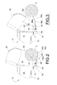
- FIG. 2 shows a partial side elevation view of baler 10 also showing bale kicker 40 having a ramp 46, a chassis mount 42 with a pivot axis 44 about which the ramp 46 pivots.
- Pivot axis 44 is arranged generally parallel to the ground and transversely with respect to the forward-rearward direction of normal baler movement across the ground.
- the bale kicker ramp 46 typically comprises an open framework structure having sufficient frame members to support a bale as it is being ejected.
- Ramp 46 comprises a forward portion 46a and a rearward portion 46b; the portions are angled relative to each other, forming an obtuse angle therebetween along bend axis 46c.
- ramp actuator 48 which interconnects chassis mount 42 and the ramp 46.
- Ramp actuator 48 is preferably a single-acting hydraulic cylinder hydraulically connected to a hydraulic control system, discussed later.
- a bale 5 has been completed and tailgate 30 moved into the raised position to allow the bale to be ejected.
- the bale 5 drops on to ramp 46 and moves toward a position generally centered over bend axis 46c.
- the weight of the bale 5 on the ramp 46 forces the ramp toward the lowered position as ramp actuator 48 is vented to allow hydraulic fluid to be freely returned to the hydraulic control system as the ramp moves downwardly.
- the bale will at some point begin to roll rearwardly away from the baler.
- Tailgate actuator 32 is pressurised for retraction to close the tailgate 30.
- Ramp actuator 48 is hydraulically connected in parallel to the retraction side of tailgate actuator 32 and thus is also pressurised to move ramp 46 toward the raised position. As the ramp 46 moves upwardly, it contacts the bale and urges it further rearward to clear the space required for tailgate 30 to complete its downward swing, shown as arc 60, and return to the closed position.
- FIG 4 depicts a hydraulic control system 50 for managing the movement of the tailgate 30 and bale kicker 40.
- Hydraulic control system 50 is a single loop hydraulic circuit receiving hydraulic fluid from a tractor hydraulic system 100, which allows selective pressurization to portions of the baler hydraulic control system 50 to cause desired tailgate directional movement.
- Tractor hydraulic system 100 is well known in the art and not discussed further in detail.
- Pressurizing the tailgate raise portion of the circuit, shown as connection 54 and providing a non-pressurised fluid return path through connection 52 supplies pressurised fluid to extension port 32a on the tailgate actuator 32 and causes is to extend and raise the tailgate.
- the retraction port 32b is vented allowing fluid to be returned to reservoir in the tractor hydraulic system 100.
- Ramp actuator 48 is also aligned to release fluid to the tractor hydraulic system 100 and allow the kicker ramp to move to the lowered position (positions shown in Figure 2 ).
- Figure 5 presents a second embodiment of the hydraulic control system 50 which includes provisions to determine the weight of bale before it is ejected from the baler.
- pressure sensor 72 and valve 74 have been incorporated into the hydraulic line connecting ramp actuator 48 to the hydraulic control system 50.
- ramp movement can suspended to allow a pressure reading to be obtained.
- Pressure in ramp actuator 48 can be correlated to bale weight.
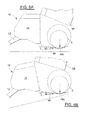
- the addition of a ramp position sensor 76, a baler level sensor 78, and a controller 70 allow the position of the ramp at the point at which bale weight is taken to be adjusted to account for variations in the terrain over which the baler is traversing as illustrated in Figure 6B .
- Consistent bale weights require that the bale position on the ramp be the same each time bale weight is determined, illustrated by contrasting Figures 6A and 6B .
- Inputs from level sensor 78 and the position of the ramp as indicated by position sensor 76 are used to determine the optimal ramp position to assure the bale is properly positioned on the ramp, preferably at the bend axis between the angled forward and rearward portions of the ramp. Once that position is reached, valve 74 would temporarily isolate the hydraulic line so that a pressure signal from sensor 72 could be received. Normal bale ejection continues from that point when valve 74 is opened to allow the ramp to continue its downward movement.
- baler level sensor 78 generates a level signal representative of baler forward-rearward pitch relative to level ground. This level signal and the position signal of the position sensor 76 provide an input to the control valve 74 thereby enabling the pressure signal indicative of weight supported by the ramp 46 to compensate for variations in ground slope.
Abstract
Description
- The present invention, relating generally to an agricultural baler for forming cylindrical bales of crop material, commonly referred to as a round baler, is specifically directed to an apparatus for ejecting the bale from the baler following bale formation to provide clearance for baler tailgate operation. More particularly, this invention is concerned with a bale kicker apparatus that allows the tailgate opening and closing cycle to occur as quickly as possible.
- For many years agricultural balers have been used to consolidate and package crop material so as to facilitate the storage and handling of the crop material for later use. Usually, a mower-conditioner cuts and conditions the crop material for windrow drying in the sun. When the cut crop material is properly dried, a baler is pulled along the windrows to pick up the crop material and form it into conveniently sized and shaped round bales. More specifically, the windrow pickup of the baler gathers the cut and windrowed crop material and lifts it into the baling chamber. In a round baler, the baling chamber consists of a pair of opposing sidewalls with a series of belts that rotate and compress the crop material into a cylindrical shape. When the bale has achieved a desired size and density, the operator wraps the bale to ensure that the bale maintains its shape and density. The operator then raises the tailgate of the baler and the bale is ejected onto the ground, generally urged by a kicker apparatus. The tailgate is then closed and the cycle repeated as necessary and desired to manage the field of cut crop material. A representative example of a round baler of this type is the round baler of
US 4,458,587 , which is incorporated in its entirety herein by reference. - When ejecting a bale, it is important to insure that the bale has rolled clear of the open tailgate before closing the tailgate to resume baling. It is also important for the cycle time for opening and closing the tailgate to be as short as possible to minimise unproductive time in the field. Experience with mechanical spring kicker devices has shown that known examples do not provide sufficient force to move the bale away from the tailgate swing area as quickly as is desired. Experience with known hydraulically actuated kickers is a tendency to slow movement of the tailgate resulting in increased tailgate opening and closing cycle time.
- It would be a great advantage to provide a bale kicker apparatus for a round baler capable of ejecting a finished bale from the baler in minimal time without interfering with the opening and closing cycle of the baler tailgate that overcomes the above-identified problems and disadvantages.
- Accordingly, it is an object of the present invention to provide a hydraulically actuated bale kicker apparatus for a round baler that ejects the bale without interfering the opening and closing of the baler tailgate and avoids the above-noted disadvantages.
- These and other objects are achieved according to a first aspect of the invention by providing an agricultural round baler, comprising:
- a ground supported main frame;
- a movable tailgate;
- a tailgate actuator for moving the tailgate between an open position and a closed position, the tailgate actuator being a double-acting hydraulic actuator having an extension port and a retraction port; and
- a bale kicker comprising:
- a movable ramp connected to the main frame for pivotal movement about a pivot axis,
- a ramp actuator for managing the pivotal position of the ramp between a raised and a lowered position; and
- a hydraulic control system interconnecting the tailgate actuator, the ramp actuator, a first connection and a second connection for providing pressurised fluid and a non-pressurised return path to the hydraulic control system,
- the ramp actuator is a single acting hydraulic actuator;
- the hydraulic control system interconnects the first connection, the retraction port of the tailgate actuator and the ramp actuator; and
- the hydraulic control system further interconnects the second connection and the extension port of the tailgate actuator.
- It is an advantage of the present invention that it provides a hydraulically powered bale kicker for a round baler that ejects the bale to clear the tailgate without slowing opening or closing of the tailgate.
- It is a still a further advantage of the present invention that it provides a bale ejecting apparatus for a round baler that is durable in construction, inexpensive of manufacture, carefree of maintenance, easily assembled, and simple and effective to use.
- According to an embodiment of the invention the hydraulic control system is a single loop, reversible hydraulic circuit suitable for receiving hydraulic fluid from a tractor hydraulic system.
- The present invention thus advantageously provides a hydraulically actuated bale kicker for a round baler that hydraulically interconnects with the hydraulic system positioning the tailgate to coordinate movement of the kicker with respect to tailgate position.
- According to a preferred aspect of the invention the ramp has a forward portion and a rearward portion being angled with respect to the forward portion.
- The present invention thus advantageously provides a bale kicker apparatus featuring ramp design capable of accommodating bales of varying sizes.
- According to a further embodiment of the invention
the round baler further comprises a controller;
the bale kicker further comprises a ramp position sensor for providing a position signal representing the pivotal position of the movable ramp to the controller; and
the hydraulic control system further comprises a pressure sensor, for providing a pressure signal representing the hydraulic pressure in the ramp actuator, and a valve arranged in the interconnection between the ramp actuator and both the first connection and the retraction port of the tailgate actuator. - The present invention thus advantageously provides a hydraulically powered bale kicker for a round baler that optionally provides a measurement of bale weight.
- According to a further embodiment of the invention the round baler further comprises a baler level sensor generating a level signal representative of the round baler forward-rearward pitch relative to level ground.
- The present invention thus advantageously provides a bale kicker apparatus with an optional bale weighing feature that compensates for variations in the slope of the terrain on which the baler is positioned.
- According to a second aspect of the invention there is provided a method for ejecting a completed bale from an agricultural round baler according to the first aspect of the invention, characterised in that it comprises the steps of:
- pressurising the first connection and venting the second connection for pressurising extension port and venting retraction port of the tailgate actuator for opening the tailgate and for venting the ramp actuator for lowering the movable ramp to the lowered position by the weight of the bale;
- venting the first connection and pressurising the second connection, for venting extension port and pressurising retraction port of the tailgate actuator for closing the tailgate and for pressurising the ramp actuator for raising the movable ramp to the raised position.
- The advantages of this invention will be apparent upon consideration of the following detailed disclosure of the invention, especially when taken in conjunction with the accompanying drawings wherein:
-
Figure 1 is an isometric view of a typical round baler shown with a tailgate in the raised position and having a bale kicker apparatus of the type on which the present invention is useful; -
Figure 2 is a partial side view of the round baler ofFigure 1 showing the tailgate in the open position and the bale kicker apparatus in the lowered position; -
Figure 3 is a partial side view of the round baler ofFigure 1 showing the tailgate in the open position and the bale kicker apparatus in the raised position; -
Figure 4 is a schematic view of the hydraulic system of a first embodiment of the present invention; -
Figure 5 is schematic view of the hydraulic system for a second embodiment of the present invention having bale weighing capability; and -
Figure 6 is a pair of partial side views,Figure 6A and Figure 6B , of the bale kicker apparatus showing bale weighing on varying and uneven terrain. - Many of the fastening, connection, processes and other means and components utilised in this invention are widely known and used in the field of the invention described, and their exact nature or type is not necessary for an understanding and use of the invention by a person skilled in the art, and they will not therefore be discussed in significant detail. Also, any reference herein to the terms "left" or "right," "up" or "down," or "top" or "bottom" are used as a matter of mere convenience, and are determined by standing at the rear of the machine facing in its normal direction of travel. Furthermore, the various components shown or described herein for any specific application of this invention can be varied or altered as anticipated by this invention and the practice of a specific application of any element may already be widely known or used in the art by persons skilled in the art and each will likewise not therefore be discussed in significant detail. When referring to the figures, like parts are numbered the same in all of the figures.
- Referring to
Figure 1 , a generally well-knownround baler 10 is shown to comprise amain frame 11 terminating forwardly in atongue 12 and rearwardly slightly beyond a transverse axle to which a pair of wheels 14 (only one shown) are mounted, thus forming a ground supported main frame 11 (not shown in detail) for forward movement across the ground. Themain frame 11 supports a series ofbelts 16 and rolls (not shown) which together with a first sidewall 17 (shown in the breakout) behind and generally parallel to coverpanel 18 and asecond sidewall 20, all together establishing a bale-formingchamber 22. Cut crop material is picked up bytransverse pickup 24 and fed into bale-formingchamber 22 where it is, as discussed above, formed into a cylindrically shaped bale. It is then wrapped with twine or a wrapping material dispensed from a wrapping mechanism generally behindshield 28. Upon completion of the wrapping process,tailgate 30 is pivoted upwardly by operation of tailgate actuator 32 (only one side shown), and the bale is ejected onto the ground. To expedite bale ejection, abale kicker 40 is provided to urge the completed bale rearwardly to provide clearance for thetailgate 30 to be returned to a closed position and baling operations to resume. Tailgateactuator 32 is preferably a double-acting hydraulic cylinder, requiring pressurised hydraulic fluid to extend and open the tailgate and also to retract and close thetailgate 30. -
Figure 2 shows a partial side elevation view ofbaler 10 also showingbale kicker 40 having aramp 46, achassis mount 42 with apivot axis 44 about which theramp 46 pivots.Pivot axis 44 is arranged generally parallel to the ground and transversely with respect to the forward-rearward direction of normal baler movement across the ground. Thebale kicker ramp 46 typically comprises an open framework structure having sufficient frame members to support a bale as it is being ejected.Ramp 46 comprises aforward portion 46a and arearward portion 46b; the portions are angled relative to each other, forming an obtuse angle therebetween alongbend axis 46c. Angling of the forward and rearward portions of theramp 46 causes the bale to move toward the bend axis as it drops onto the ramp thereby providing a consistent position on the ramp from bale to bale. A consistent bale position on theramp 46 is required for determining the weight of the bale, discussed in greater detail later herein. The pivotal position oframp 46 is managed byramp actuator 48 which interconnectschassis mount 42 and theramp 46.Ramp actuator 48 is preferably a single-acting hydraulic cylinder hydraulically connected to a hydraulic control system, discussed later. - As presented in
Figure 2 , abale 5 has been completed andtailgate 30 moved into the raised position to allow the bale to be ejected. Thebale 5 drops on to ramp 46 and moves toward a position generally centered overbend axis 46c. The weight of thebale 5 on theramp 46 forces the ramp toward the lowered position asramp actuator 48 is vented to allow hydraulic fluid to be freely returned to the hydraulic control system as the ramp moves downwardly. As the ramp continues its downward movement, the bale will at some point begin to roll rearwardly away from the baler. - Referring now to
Figure 3 , thebale 5 is resting on the ground and thetailgate 30 closing has commenced.Tailgate actuator 32 is pressurised for retraction to close thetailgate 30.Ramp actuator 48 is hydraulically connected in parallel to the retraction side oftailgate actuator 32 and thus is also pressurised to moveramp 46 toward the raised position. As theramp 46 moves upwardly, it contacts the bale and urges it further rearward to clear the space required fortailgate 30 to complete its downward swing, shown asarc 60, and return to the closed position. -
Figure 4 depicts ahydraulic control system 50 for managing the movement of thetailgate 30 andbale kicker 40.Hydraulic control system 50 is a single loop hydraulic circuit receiving hydraulic fluid from a tractorhydraulic system 100, which allows selective pressurization to portions of the balerhydraulic control system 50 to cause desired tailgate directional movement. Tractorhydraulic system 100 is well known in the art and not discussed further in detail. Pressurizing the tailgate raise portion of the circuit, shown asconnection 54 and providing a non-pressurised fluid return path throughconnection 52 supplies pressurised fluid toextension port 32a on thetailgate actuator 32 and causes is to extend and raise the tailgate. Theretraction port 32b is vented allowing fluid to be returned to reservoir in the tractorhydraulic system 100.Ramp actuator 48 is also aligned to release fluid to the tractorhydraulic system 100 and allow the kicker ramp to move to the lowered position (positions shown inFigure 2 ). - Reversing the supply and return lines to supply pressurised fluid to
connection 52 and vent thereturn connection 54 to the tractor hydraulic reservoir supplies pressurised fluid to theramp actuator 48 and theretraction side 32b oftailgate actuator 32.Orifice 62 disposed in the tailgate actuator hydraulic extension line restricts the flow of hydraulic fluid thereby controlling the rate of tailgate closure and prevent it from slamming closed. Theorifice 62 is bypassed during the extension cycle bycheck valve 64 as the weight of the tailgate itself provides sufficient resistance to tailgate movement. The upward movement of the ramp urges the completed bale out of the way of the tailgate closure path (arc 60 inFigures 2 and 3 ) without impeding the rate of tailgate closure, which is controlled by theorifice 62. The additional fluid required to extendramp actuator 48 has a negligible effect on the rate at which the tailgate actuator retracts. - Referring now to
Figures 5 and6 ,Figure 5 presents a second embodiment of thehydraulic control system 50 which includes provisions to determine the weight of bale before it is ejected from the baler. In this embodiment,pressure sensor 72 andvalve 74 have been incorporated into the hydraulic line connectingramp actuator 48 to thehydraulic control system 50. By closingvalve 74 during the tailgate opening-ramp lowering cycle, ramp movement can suspended to allow a pressure reading to be obtained. Pressure inramp actuator 48 can be correlated to bale weight. The addition of aramp position sensor 76, abaler level sensor 78, and acontroller 70 allow the position of the ramp at the point at which bale weight is taken to be adjusted to account for variations in the terrain over which the baler is traversing as illustrated inFigure 6B . Consistent bale weights require that the bale position on the ramp be the same each time bale weight is determined, illustrated by contrastingFigures 6A and 6B . Inputs fromlevel sensor 78 and the position of the ramp as indicated byposition sensor 76 are used to determine the optimal ramp position to assure the bale is properly positioned on the ramp, preferably at the bend axis between the angled forward and rearward portions of the ramp. Once that position is reached,valve 74 would temporarily isolate the hydraulic line so that a pressure signal fromsensor 72 could be received. Normal bale ejection continues from that point whenvalve 74 is opened to allow the ramp to continue its downward movement. - It is clear that the
baler level sensor 78 generates a level signal representative of baler forward-rearward pitch relative to level ground. This level signal and the position signal of theposition sensor 76 provide an input to thecontrol valve 74 thereby enabling the pressure signal indicative of weight supported by theramp 46 to compensate for variations in ground slope. - It will be understood that changes in the details, materials, steps and arrangements of parts which have been described and illustrated to explain the the invention will occur to and may be made by those skilled in the art upon a reading of this disclosure without departing from the scope of the inventions as defined by the claims.
Claims (9)
- An agricultural round baler (10), comprising:a ground supported main frame (11);a movable tailgate (30);a tailgate actuator (32) for moving the tailgate (30) between an open position and a closed position, the tailgate actuator (32) being a double-acting hydraulic actuator having an extension port (32a) and a retraction port (32b); anda bale kicker (40) comprising:characterised in that:- a movable ramp (46) connected to the main frame (11) for pivotal movement about a pivot axis (44);- a ramp actuator (48) for managing the pivotal position of the ramp (46) between a raised and a lowered position; and- a hydraulic control system (50) interconnecting the tailgate actuator (32), the ramp actuator (48), and first and second connections (52, 54) for providing pressurised fluid and a non-pressurised return path to the hydraulic control system (50),the ramp actuator (48) is a single acting hydraulic actuator;the hydraulic control system (50) interconnects the first connection (52), the retraction port (32b) of the tailgate actuator (32) and the ramp actuator (48); andthe hydraulic control system (50) further interconnects the second connection (54) and the extension port (32a) of the tailgate actuator (32).
- An agricultural round baler according to claim 1, characterised in that the hydraulic control system (50) is a single loop, reversible hydraulic circuit suitable for receiving hydraulic fluid from a tractor hydraulic system (100).
- An agricultural round baler according to claim 1 or 2, characterised in that the ramp (46) has a forward portion (46a) and a rearward portion (46b) being angled with respect to the forward portion (46a).
- An agricultural round baler according to any of the previous claims, characterised in that the hydraulic control system (50) further comprises an orifice (62) bypassed by a check valve (64) arranged in the interconnection between the second connection (54) and the extension port (32a) of the tailgate actuator (32) for controlling the rate of tailgate closure.
- An agricultural round baler according to any of the previous claims, characterised in that:the round baler (10) further comprises a controller (70);the bale kicker (40) further comprises a ramp position sensor (76) for providing a position signal representing the pivotal position of the movable ramp (46) to the controller (70); andthe hydraulic control system (50) further comprises a pressure sensor (72), for providing a pressure signal representing the hydraulic pressure in the ramp actuator (48), and a valve (74) arranged in the interconnection between the ramp actuator (48) and both the first connection (52) and the retraction port (32b) of the tailgate actuator (32).
- An agricultural round baler according to claim 5, characterised in that the round baler (10) further comprises a baler level sensor (78) generating a level signal representative of the round baler (10) forward-rearward pitch relative to level ground.
- A method for ejecting a completed bale (5) from an agricultural round baler (10) according to any of the previous claims, characterised in that it comprises the steps of:pressurising the first connection (54) and venting the second connection (52) for pressurising extension port (32a) and venting retraction port (32b) of the tailgate actuator (32) for opening the tailgate (30) and for venting the ramp actuator (48) for lowering the movable ramp (46) to the lowered position by the weight of the bale (5); andventing the first connection (54) and pressurising the second connection (52) for venting extension port (32a) and pressurising retraction port (32b) of the tailgate actuator (32) for closing the tailgate (30) and for pressurising the ramp actuator (48) for raising the movable ramp (46) to the raised position.
- A method according to claim 7 when referring to claim 5 or any dependent claim thereof, characterised in that during the step of pressurising the first connection (54) and venting the second connection (52) it further comprises the steps of:the ramp position sensor (76) providing a position signal representing the pivotal position of the movable ramp (46) to the controller (70);the controller (70) closing valve (74) to suspend the movement of the movable ramp (46) movement;the pressure sensor (72) providing a pressure signal representing the hydraulic pressure in the ramp actuator (48) to the controller (70) for correlating this pressure signal to bale weight; andthe controller (70) opening valve (74) to resume the movement of the movable ramp (46).
- A method according to claim 8 when referring to claim 6 or any dependent claim thereof, characterised in that it comprises the additional step of the baler level sensor (78) providing a level signal representative of the round baler (10) forward-rearward pitch relative to level ground to the controller (70) for determining the pivotal position of the movable ramp (46) at which the movement is to be suspended to compensate for variations in ground slope when providing the pressure signal to the controller (70) for correlating this pressure to bale weight.
Applications Claiming Priority (1)
| Application Number | Priority Date | Filing Date | Title |
|---|---|---|---|
| US12/045,631 US7805914B2 (en) | 2008-03-10 | 2008-03-10 | Hydraulic bale kicker with optional weighing device |
Publications (3)
| Publication Number | Publication Date |
|---|---|
| EP2100498A2 true EP2100498A2 (en) | 2009-09-16 |
| EP2100498A3 EP2100498A3 (en) | 2009-12-23 |
| EP2100498B1 EP2100498B1 (en) | 2011-08-17 |
Family
ID=40756585
Family Applications (1)
| Application Number | Title | Priority Date | Filing Date |
|---|---|---|---|
| EP09154768A Active EP2100498B1 (en) | 2008-03-10 | 2009-03-10 | Hydraulic bale kicker with weighing device |
Country Status (3)
| Country | Link |
|---|---|
| US (1) | US7805914B2 (en) |
| EP (1) | EP2100498B1 (en) |
| AT (1) | ATE520298T1 (en) |
Cited By (7)
| Publication number | Priority date | Publication date | Assignee | Title |
|---|---|---|---|---|
| EP2384617A1 (en) * | 2010-05-04 | 2011-11-09 | Deere & Company | Baler and method of controlling a movement of a large cylindrical bale |
| EP2875716A1 (en) * | 2013-11-25 | 2015-05-27 | CNH Industrial Belgium nv | Fluid circuit for bale ejection |
| EP2875717A1 (en) * | 2013-11-25 | 2015-05-27 | CNH Industrial Belgium nv | Fluid circuit for bale ejection with restricted flow |
| EP3677113A1 (en) * | 2019-01-02 | 2020-07-08 | Deere & Company | Bale weight measurement and control system using lift gate |
| US20220015300A1 (en) * | 2020-07-20 | 2022-01-20 | Deere & Company | Round baler with bale holder in gate |
| ES2946413A1 (en) * | 2022-01-16 | 2023-07-18 | Fernandez Sante Marcos | DEVICE TO UNLOAD THE BALE IN A CONTROLLED WAY IN AGRICULTURAL ROUND BALERS (Machine-translation by Google Translate, not legally binding) |
| US11771010B2 (en) | 2020-07-20 | 2023-10-03 | Deere & Company | Round baler with position controlled take-up roller, and method of operating a round baler |
Families Citing this family (17)
| Publication number | Priority date | Publication date | Assignee | Title |
|---|---|---|---|---|
| US20120189417A1 (en) * | 2010-12-27 | 2012-07-26 | Agco Corporation | Passive Ramp With Ramp Down Switch |
| DE102011079940A1 (en) * | 2011-07-27 | 2013-01-31 | Deere & Company | Round baler |
| US9295198B2 (en) | 2012-05-09 | 2016-03-29 | Cnh Industrial America Llc | Density system bypass for a round baler |
| US9297688B2 (en) | 2012-12-21 | 2016-03-29 | Cnh Industrial America Llc | Weighing round bales |
| US8776679B1 (en) * | 2013-03-15 | 2014-07-15 | Cnh Industrial Canada, Ltd. | Semi-automatic bale ejection sequence |
| JP6335453B2 (en) * | 2013-08-23 | 2018-05-30 | 株式会社Ihiアグリテック | Roll baler |
| EP3036986B1 (en) * | 2014-12-24 | 2019-10-16 | CNH Industrial Belgium nv | Weighing round bales |
| US9622417B2 (en) | 2015-05-01 | 2017-04-18 | Cnh Industrial America Llc | Tailgate motion adjustment system |
| US11425863B2 (en) * | 2015-07-14 | 2022-08-30 | Clemson University Research Foundation | Round bale weighing method and system |
| US10918020B2 (en) * | 2015-09-30 | 2021-02-16 | Deere & Company | Baler and accumulator control system |
| US10595465B2 (en) | 2016-04-08 | 2020-03-24 | Deere & Company | Agricultural baler including baler gate control system |
| US10091943B2 (en) | 2016-09-06 | 2018-10-09 | Deere & Company | Round module weighing using differential pressure sensing |
| WO2018056805A1 (en) * | 2016-09-23 | 2018-03-29 | Lely Patent N.V. | Apparatus and method for forming and ejecting a bale depending on a ramp sensor |
| US10385605B2 (en) * | 2016-11-16 | 2019-08-20 | Vermeer Manufacturing Company | Tailgate sensor |
| IT201700093544A1 (en) * | 2017-08-11 | 2019-02-11 | Kverneland Group Ravenna Srl | CONTAINABLE BOTTLE WITH A TRACTOR FOR REALIZING ROUND BALES AND METHOD FOR CREATING ROUND BALES |
| US11612108B2 (en) | 2019-12-16 | 2023-03-28 | Cnh Industrial America Llc | Hydraulic system for agricultural baler |
| CN114577318B (en) * | 2022-01-25 | 2023-12-19 | 常州纺织服装职业技术学院 | Vehicle-mounted weighing module and sensing method thereof |
Citations (1)
| Publication number | Priority date | Publication date | Assignee | Title |
|---|---|---|---|---|
| US4458587A (en) | 1982-03-01 | 1984-07-10 | Sperry Corporation | Adjustable bale kicker |
Family Cites Families (25)
| Publication number | Priority date | Publication date | Assignee | Title |
|---|---|---|---|---|
| US3567072A (en) | 1968-12-24 | 1971-03-02 | Donald Tenhulzen | Weighing and automatic dumping attachment for combines and like machines |
| US4362097A (en) | 1980-12-29 | 1982-12-07 | Rogers Laurence J D | Apparatus for determining weight of cylindrical hay bales |
| GB2196294B (en) * | 1986-10-20 | 1991-01-23 | Deere & Co | Machine for forming cylindrical bales of crop |
| US4742880A (en) | 1987-04-15 | 1988-05-10 | Hesston Corporation | Method and apparatus for determining the weight of bales issuing from a crop baler |
| GB2203986B (en) * | 1987-04-27 | 1990-12-19 | Deere & Co | Machine for forming cylindrical bales of crop |
| EP0424489B1 (en) * | 1989-05-09 | 1992-11-04 | Wirth, Gallo Messtechnik AG | Axle-spring weighing device system |
| US5263410A (en) | 1991-03-29 | 1993-11-23 | Olin Ray L | Valve and hydraulic circuit for a bale discharge apparatus |
| US5384436A (en) | 1993-06-30 | 1995-01-24 | Pritchard; Gary E. | Apparatus and method for electrically weighing bales in a mobile crop baler |
| US5717167A (en) * | 1995-01-24 | 1998-02-10 | Lts Scale Corp. | Device and method for weighing solid waste with an angle-correction scale |
| US5622104A (en) | 1995-08-28 | 1997-04-22 | Gehl Company | Cylindrical baler having hydraulic circuit for controlling bale density and tailgate operation |
| US5811739A (en) | 1997-03-28 | 1998-09-22 | Palmore; Donald | Mobile bale weighing device |
| US5959257A (en) * | 1998-04-15 | 1999-09-28 | Harvestmaster, Inc. | System for weighing material on a conveyor |
| DE19835166C2 (en) | 1998-08-04 | 2000-06-15 | Case Harvesting Sys Gmbh | Method and device for determining the baling density of bales |
| DE19906611A1 (en) | 1999-02-17 | 2000-08-24 | Lely Welger Maschinenfabrik Gm | Agricultural baler with a weighing device |
| DE19910555A1 (en) | 1999-03-10 | 2000-09-14 | Lely Welger Maschinenfabrik Gm | Agricultural round baler with a weighing device |
| US6892632B1 (en) | 2001-08-10 | 2005-05-17 | Gehl Company | Jointed bale kicker for a round baler |
| US6807901B2 (en) * | 2002-08-05 | 2004-10-26 | Vermeer Manufacturing Company | Two-stage spring loaded bale ramp |
| DE10241215A1 (en) | 2002-09-06 | 2004-03-18 | Deere & Company, Moline | Round baler with weighing device |
| DE10303201C5 (en) | 2003-01-28 | 2015-03-12 | Lely Vermeer Maschinenfabrik GmbH | Round baler for agricultural stalks |
| DE10322333A1 (en) | 2003-05-17 | 2004-12-02 | Deere & Company, Moline | Device for measuring the weight of a bale |
| US20050257513A1 (en) | 2004-04-01 | 2005-11-24 | Smith Kevin M | Hydraulic bale ramp |
| US20050217233A1 (en) * | 2004-04-01 | 2005-10-06 | Smith Kevin M | Hydraulic bale ramp |
| US7197979B2 (en) | 2005-06-10 | 2007-04-03 | Deere & Company | Controlled bale ejection mechanism |
| US7472649B1 (en) * | 2007-09-28 | 2009-01-06 | Deere & Company | Sequence and timing control for large round baler ejection device |
| DE102007058313B4 (en) * | 2007-12-04 | 2016-03-10 | Deere & Company | Arrangement for adjusting the position of a pick-up drum and a hold-down of an agricultural harvester |
-
2008
- 2008-03-10 US US12/045,631 patent/US7805914B2/en active Active
-
2009
- 2009-03-10 EP EP09154768A patent/EP2100498B1/en active Active
- 2009-03-10 AT AT09154768T patent/ATE520298T1/en not_active IP Right Cessation
Patent Citations (1)
| Publication number | Priority date | Publication date | Assignee | Title |
|---|---|---|---|---|
| US4458587A (en) | 1982-03-01 | 1984-07-10 | Sperry Corporation | Adjustable bale kicker |
Cited By (9)
| Publication number | Priority date | Publication date | Assignee | Title |
|---|---|---|---|---|
| EP2384617A1 (en) * | 2010-05-04 | 2011-11-09 | Deere & Company | Baler and method of controlling a movement of a large cylindrical bale |
| US8113113B2 (en) | 2010-05-04 | 2012-02-14 | Deere & Company | Discharged bale control device and control method |
| EP2875716A1 (en) * | 2013-11-25 | 2015-05-27 | CNH Industrial Belgium nv | Fluid circuit for bale ejection |
| EP2875717A1 (en) * | 2013-11-25 | 2015-05-27 | CNH Industrial Belgium nv | Fluid circuit for bale ejection with restricted flow |
| EP3677113A1 (en) * | 2019-01-02 | 2020-07-08 | Deere & Company | Bale weight measurement and control system using lift gate |
| US20220015300A1 (en) * | 2020-07-20 | 2022-01-20 | Deere & Company | Round baler with bale holder in gate |
| US11771010B2 (en) | 2020-07-20 | 2023-10-03 | Deere & Company | Round baler with position controlled take-up roller, and method of operating a round baler |
| US11825775B2 (en) * | 2020-07-20 | 2023-11-28 | Deere & Company | Round baler with bale holder in gate |
| ES2946413A1 (en) * | 2022-01-16 | 2023-07-18 | Fernandez Sante Marcos | DEVICE TO UNLOAD THE BALE IN A CONTROLLED WAY IN AGRICULTURAL ROUND BALERS (Machine-translation by Google Translate, not legally binding) |
Also Published As
| Publication number | Publication date |
|---|---|
| ATE520298T1 (en) | 2011-09-15 |
| US20090223196A1 (en) | 2009-09-10 |
| EP2100498B1 (en) | 2011-08-17 |
| EP2100498A3 (en) | 2009-12-23 |
| US7805914B2 (en) | 2010-10-05 |
Similar Documents
| Publication | Publication Date | Title |
|---|---|---|
| EP2100498B1 (en) | Hydraulic bale kicker with weighing device | |
| US7849791B2 (en) | Optimized baler tailgate cycle | |
| EP2974591B1 (en) | A carriage assembly, baler and a method for moving a bale from an agricultural baler to a carriage assembly | |
| CA2849906C (en) | Baler attachment for optionally changing the orientation of bales being released from a baler | |
| CA2540781C (en) | Controlled bale ejection mechanism | |
| EP2974590B1 (en) | Carriage assembly, agricultural baler with such and method for moving a bale on a bale carriage | |
| US7640852B1 (en) | Round baler belt-tensioning cylinder arrangement also used for bale ejection | |
| US9241443B2 (en) | Gate position control of round bale discharge | |
| EP2974589B1 (en) | A carriage assembly, a baler and a method for deploying the carriage assembly | |
| EP3003008B1 (en) | Bale eject linkage and methods of use | |
| EP2875716B1 (en) | Fluid circuit for bale ejection | |
| EP2614703B1 (en) | Crop parameter dependent bale chamber configuration adaptation | |
| CA1318179C (en) | Support assembly attached to a large round baler for forming a bale discharge ramp | |
| EP2384617B1 (en) | Baler and method of controlling a movement of a large cylindrical bale | |
| EP2875717B1 (en) | Fluid circuit for bale ejection with restricted flow | |
| EP3087827B1 (en) | Tailgate motion adjustment system | |
| CA2307245C (en) | Bale wrapping implement | |
| US6033172A (en) | Bale turning apparatus | |
| CA2307244C (en) | Bale wrapping implement | |
| NL2013287B1 (en) | Bale forming apparatus with a retaining device. | |
| IE86474B1 (en) | A bale handling apparatus |
Legal Events
| Date | Code | Title | Description |
|---|---|---|---|
| PUAI | Public reference made under article 153(3) epc to a published international application that has entered the european phase |
Free format text: ORIGINAL CODE: 0009012 |
|
| AK | Designated contracting states |
Kind code of ref document: A2 Designated state(s): AT BE BG CH CY CZ DE DK EE ES FI FR GB GR HR HU IE IS IT LI LT LU LV MC MK MT NL NO PL PT RO SE SI SK TR |
|
| AX | Request for extension of the european patent |
Extension state: AL BA RS |
|
| PUAL | Search report despatched |
Free format text: ORIGINAL CODE: 0009013 |
|
| AK | Designated contracting states |
Kind code of ref document: A3 Designated state(s): AT BE BG CH CY CZ DE DK EE ES FI FR GB GR HR HU IE IS IT LI LT LU LV MC MK MT NL NO PL PT RO SE SI SK TR |
|
| AX | Request for extension of the european patent |
Extension state: AL BA RS |
|
| 17P | Request for examination filed |
Effective date: 20100623 |
|
| AKX | Designation fees paid |
Designated state(s): AT BE BG CH CY CZ DE DK EE ES FI FR GB GR HR HU IE IS IT LI LT LU LV MC MK MT NL NO PL PT RO SE SI SK TR |
|
| GRAP | Despatch of communication of intention to grant a patent |
Free format text: ORIGINAL CODE: EPIDOSNIGR1 |
|
| RTI1 | Title (correction) |
Free format text: HYDRAULIC BALE KICKER WITH WEIGHING DEVICE |
|
| GRAS | Grant fee paid |
Free format text: ORIGINAL CODE: EPIDOSNIGR3 |
|
| GRAA | (expected) grant |
Free format text: ORIGINAL CODE: 0009210 |
|
| AK | Designated contracting states |
Kind code of ref document: B1 Designated state(s): AT BE BG CH CY CZ DE DK EE ES FI FR GB GR HR HU IE IS IT LI LT LU LV MC MK MT NL NO PL PT RO SE SI SK TR |
|
| REG | Reference to a national code |
Ref country code: GB Ref legal event code: FG4D |
|
| REG | Reference to a national code |
Ref country code: CH Ref legal event code: EP |
|
| REG | Reference to a national code |
Ref country code: IE Ref legal event code: FG4D |
|
| REG | Reference to a national code |
Ref country code: DE Ref legal event code: R096 Ref document number: 602009002145 Country of ref document: DE Effective date: 20111020 |
|
| REG | Reference to a national code |
Ref country code: NL Ref legal event code: T3 |
|
| LTIE | Lt: invalidation of european patent or patent extension |
Effective date: 20110817 |
|
| PG25 | Lapsed in a contracting state [announced via postgrant information from national office to epo] |
Ref country code: FI Free format text: LAPSE BECAUSE OF FAILURE TO SUBMIT A TRANSLATION OF THE DESCRIPTION OR TO PAY THE FEE WITHIN THE PRESCRIBED TIME-LIMIT Effective date: 20110817 Ref country code: LT Free format text: LAPSE BECAUSE OF FAILURE TO SUBMIT A TRANSLATION OF THE DESCRIPTION OR TO PAY THE FEE WITHIN THE PRESCRIBED TIME-LIMIT Effective date: 20110817 Ref country code: NO Free format text: LAPSE BECAUSE OF FAILURE TO SUBMIT A TRANSLATION OF THE DESCRIPTION OR TO PAY THE FEE WITHIN THE PRESCRIBED TIME-LIMIT Effective date: 20111117 Ref country code: IS Free format text: LAPSE BECAUSE OF FAILURE TO SUBMIT A TRANSLATION OF THE DESCRIPTION OR TO PAY THE FEE WITHIN THE PRESCRIBED TIME-LIMIT Effective date: 20111217 Ref country code: PT Free format text: LAPSE BECAUSE OF FAILURE TO SUBMIT A TRANSLATION OF THE DESCRIPTION OR TO PAY THE FEE WITHIN THE PRESCRIBED TIME-LIMIT Effective date: 20111219 Ref country code: SE Free format text: LAPSE BECAUSE OF FAILURE TO SUBMIT A TRANSLATION OF THE DESCRIPTION OR TO PAY THE FEE WITHIN THE PRESCRIBED TIME-LIMIT Effective date: 20110817 |
|
| REG | Reference to a national code |
Ref country code: AT Ref legal event code: MK05 Ref document number: 520298 Country of ref document: AT Kind code of ref document: T Effective date: 20110817 |
|
| PG25 | Lapsed in a contracting state [announced via postgrant information from national office to epo] |
Ref country code: GR Free format text: LAPSE BECAUSE OF FAILURE TO SUBMIT A TRANSLATION OF THE DESCRIPTION OR TO PAY THE FEE WITHIN THE PRESCRIBED TIME-LIMIT Effective date: 20111118 Ref country code: PL Free format text: LAPSE BECAUSE OF FAILURE TO SUBMIT A TRANSLATION OF THE DESCRIPTION OR TO PAY THE FEE WITHIN THE PRESCRIBED TIME-LIMIT Effective date: 20110817 Ref country code: AT Free format text: LAPSE BECAUSE OF FAILURE TO SUBMIT A TRANSLATION OF THE DESCRIPTION OR TO PAY THE FEE WITHIN THE PRESCRIBED TIME-LIMIT Effective date: 20110817 Ref country code: SI Free format text: LAPSE BECAUSE OF FAILURE TO SUBMIT A TRANSLATION OF THE DESCRIPTION OR TO PAY THE FEE WITHIN THE PRESCRIBED TIME-LIMIT Effective date: 20110817 Ref country code: CY Free format text: LAPSE BECAUSE OF FAILURE TO SUBMIT A TRANSLATION OF THE DESCRIPTION OR TO PAY THE FEE WITHIN THE PRESCRIBED TIME-LIMIT Effective date: 20110817 Ref country code: LV Free format text: LAPSE BECAUSE OF FAILURE TO SUBMIT A TRANSLATION OF THE DESCRIPTION OR TO PAY THE FEE WITHIN THE PRESCRIBED TIME-LIMIT Effective date: 20110817 |
|
| PG25 | Lapsed in a contracting state [announced via postgrant information from national office to epo] |
Ref country code: SK Free format text: LAPSE BECAUSE OF FAILURE TO SUBMIT A TRANSLATION OF THE DESCRIPTION OR TO PAY THE FEE WITHIN THE PRESCRIBED TIME-LIMIT Effective date: 20110817 Ref country code: CZ Free format text: LAPSE BECAUSE OF FAILURE TO SUBMIT A TRANSLATION OF THE DESCRIPTION OR TO PAY THE FEE WITHIN THE PRESCRIBED TIME-LIMIT Effective date: 20110817 |
|
| PG25 | Lapsed in a contracting state [announced via postgrant information from national office to epo] |
Ref country code: EE Free format text: LAPSE BECAUSE OF FAILURE TO SUBMIT A TRANSLATION OF THE DESCRIPTION OR TO PAY THE FEE WITHIN THE PRESCRIBED TIME-LIMIT Effective date: 20110817 Ref country code: RO Free format text: LAPSE BECAUSE OF FAILURE TO SUBMIT A TRANSLATION OF THE DESCRIPTION OR TO PAY THE FEE WITHIN THE PRESCRIBED TIME-LIMIT Effective date: 20110817 |
|
| PLBE | No opposition filed within time limit |
Free format text: ORIGINAL CODE: 0009261 |
|
| STAA | Information on the status of an ep patent application or granted ep patent |
Free format text: STATUS: NO OPPOSITION FILED WITHIN TIME LIMIT |
|
| PG25 | Lapsed in a contracting state [announced via postgrant information from national office to epo] |
Ref country code: DK Free format text: LAPSE BECAUSE OF FAILURE TO SUBMIT A TRANSLATION OF THE DESCRIPTION OR TO PAY THE FEE WITHIN THE PRESCRIBED TIME-LIMIT Effective date: 20110817 |
|
| 26N | No opposition filed |
Effective date: 20120521 |
|
| REG | Reference to a national code |
Ref country code: DE Ref legal event code: R097 Ref document number: 602009002145 Country of ref document: DE Effective date: 20120521 |
|
| PG25 | Lapsed in a contracting state [announced via postgrant information from national office to epo] |
Ref country code: MC Free format text: LAPSE BECAUSE OF NON-PAYMENT OF DUE FEES Effective date: 20120331 |
|
| PG25 | Lapsed in a contracting state [announced via postgrant information from national office to epo] |
Ref country code: HR Free format text: LAPSE BECAUSE OF FAILURE TO SUBMIT A TRANSLATION OF THE DESCRIPTION OR TO PAY THE FEE WITHIN THE PRESCRIBED TIME-LIMIT Effective date: 20120404 |
|
| REG | Reference to a national code |
Ref country code: IE Ref legal event code: MM4A |
|
| PG25 | Lapsed in a contracting state [announced via postgrant information from national office to epo] |
Ref country code: IE Free format text: LAPSE BECAUSE OF NON-PAYMENT OF DUE FEES Effective date: 20120310 |
|
| PG25 | Lapsed in a contracting state [announced via postgrant information from national office to epo] |
Ref country code: MK Free format text: LAPSE BECAUSE OF FAILURE TO SUBMIT A TRANSLATION OF THE DESCRIPTION OR TO PAY THE FEE WITHIN THE PRESCRIBED TIME-LIMIT Effective date: 20110817 |
|
| PG25 | Lapsed in a contracting state [announced via postgrant information from national office to epo] |
Ref country code: ES Free format text: LAPSE BECAUSE OF FAILURE TO SUBMIT A TRANSLATION OF THE DESCRIPTION OR TO PAY THE FEE WITHIN THE PRESCRIBED TIME-LIMIT Effective date: 20111128 |
|
| PG25 | Lapsed in a contracting state [announced via postgrant information from national office to epo] |
Ref country code: BG Free format text: LAPSE BECAUSE OF FAILURE TO SUBMIT A TRANSLATION OF THE DESCRIPTION OR TO PAY THE FEE WITHIN THE PRESCRIBED TIME-LIMIT Effective date: 20111117 |
|
| PG25 | Lapsed in a contracting state [announced via postgrant information from national office to epo] |
Ref country code: MT Free format text: LAPSE BECAUSE OF FAILURE TO SUBMIT A TRANSLATION OF THE DESCRIPTION OR TO PAY THE FEE WITHIN THE PRESCRIBED TIME-LIMIT Effective date: 20110817 |
|
| REG | Reference to a national code |
Ref country code: CH Ref legal event code: PL |
|
| PG25 | Lapsed in a contracting state [announced via postgrant information from national office to epo] |
Ref country code: HR Free format text: LAPSE BECAUSE OF FAILURE TO SUBMIT A TRANSLATION OF THE DESCRIPTION OR TO PAY THE FEE WITHIN THE PRESCRIBED TIME-LIMIT Effective date: 20110817 |
|
| PG25 | Lapsed in a contracting state [announced via postgrant information from national office to epo] |
Ref country code: CH Free format text: LAPSE BECAUSE OF NON-PAYMENT OF DUE FEES Effective date: 20130331 Ref country code: LI Free format text: LAPSE BECAUSE OF NON-PAYMENT OF DUE FEES Effective date: 20130331 |
|
| REG | Reference to a national code |
Ref country code: DE Ref legal event code: R082 Ref document number: 602009002145 Country of ref document: DE Representative=s name: PATENTANWAELTE WALLACH, KOCH & PARTNER, DE |
|
| PG25 | Lapsed in a contracting state [announced via postgrant information from national office to epo] |
Ref country code: TR Free format text: LAPSE BECAUSE OF FAILURE TO SUBMIT A TRANSLATION OF THE DESCRIPTION OR TO PAY THE FEE WITHIN THE PRESCRIBED TIME-LIMIT Effective date: 20110817 |
|
| PG25 | Lapsed in a contracting state [announced via postgrant information from national office to epo] |
Ref country code: LU Free format text: LAPSE BECAUSE OF NON-PAYMENT OF DUE FEES Effective date: 20120310 |
|
| REG | Reference to a national code |
Ref country code: DE Ref legal event code: R082 Ref document number: 602009002145 Country of ref document: DE Representative=s name: PATENTANWAELTE WALLACH, KOCH, DR. HAIBACH, FEL, DE Effective date: 20140428 Ref country code: DE Ref legal event code: R082 Ref document number: 602009002145 Country of ref document: DE Representative=s name: PATENTANWAELTE WALLACH, KOCH & PARTNER, DE Effective date: 20140428 Ref country code: DE Ref legal event code: R081 Ref document number: 602009002145 Country of ref document: DE Owner name: CNH INDUSTRIAL BELGIUM NV, BE Free format text: FORMER OWNER: CNH BELGIUM NV, ZEDELGEM, BE Effective date: 20140428 |
|
| PG25 | Lapsed in a contracting state [announced via postgrant information from national office to epo] |
Ref country code: HU Free format text: LAPSE BECAUSE OF FAILURE TO SUBMIT A TRANSLATION OF THE DESCRIPTION OR TO PAY THE FEE WITHIN THE PRESCRIBED TIME-LIMIT Effective date: 20090310 |
|
| REG | Reference to a national code |
Ref country code: FR Ref legal event code: CD Owner name: CNH INDUSTRIAL BELGIUM NV Effective date: 20140725 |
|
| REG | Reference to a national code |
Ref country code: NL Ref legal event code: TD Effective date: 20150714 |
|
| REG | Reference to a national code |
Ref country code: NL Ref legal event code: TD Effective date: 20150714 |
|
| REG | Reference to a national code |
Ref country code: FR Ref legal event code: PLFP Year of fee payment: 8 |
|
| REG | Reference to a national code |
Ref country code: FR Ref legal event code: PLFP Year of fee payment: 9 |
|
| REG | Reference to a national code |
Ref country code: FR Ref legal event code: PLFP Year of fee payment: 10 |
|
| PGFP | Annual fee paid to national office [announced via postgrant information from national office to epo] |
Ref country code: NL Payment date: 20200325 Year of fee payment: 12 |
|
| PGFP | Annual fee paid to national office [announced via postgrant information from national office to epo] |
Ref country code: BE Payment date: 20200320 Year of fee payment: 12 |
|
| REG | Reference to a national code |
Ref country code: DE Ref legal event code: R082 Ref document number: 602009002145 Country of ref document: DE Representative=s name: MEISSNER BOLTE PATENTANWAELTE RECHTSANWAELTE P, DE |
|
| REG | Reference to a national code |
Ref country code: DE Ref legal event code: R084 Ref document number: 602009002145 Country of ref document: DE |
|
| REG | Reference to a national code |
Ref country code: NL Ref legal event code: MM Effective date: 20210401 |
|
| REG | Reference to a national code |
Ref country code: BE Ref legal event code: MM Effective date: 20210331 |
|
| PG25 | Lapsed in a contracting state [announced via postgrant information from national office to epo] |
Ref country code: NL Free format text: LAPSE BECAUSE OF NON-PAYMENT OF DUE FEES Effective date: 20210401 |
|
| PG25 | Lapsed in a contracting state [announced via postgrant information from national office to epo] |
Ref country code: BE Free format text: LAPSE BECAUSE OF NON-PAYMENT OF DUE FEES Effective date: 20210331 |
|
| PGFP | Annual fee paid to national office [announced via postgrant information from national office to epo] |
Ref country code: FR Payment date: 20230322 Year of fee payment: 15 |
|
| PGFP | Annual fee paid to national office [announced via postgrant information from national office to epo] |
Ref country code: IT Payment date: 20230313 Year of fee payment: 15 Ref country code: GB Payment date: 20230322 Year of fee payment: 15 Ref country code: DE Payment date: 20230323 Year of fee payment: 15 |