EP2099373B1 - Volar plate fixation device - Google Patents
Volar plate fixation device Download PDFInfo
- Publication number
- EP2099373B1 EP2099373B1 EP07854942.5A EP07854942A EP2099373B1 EP 2099373 B1 EP2099373 B1 EP 2099373B1 EP 07854942 A EP07854942 A EP 07854942A EP 2099373 B1 EP2099373 B1 EP 2099373B1
- Authority
- EP
- European Patent Office
- Prior art keywords
- holes
- volar plate
- distal
- bone
- row
- Prior art date
- Legal status (The legal status is an assumption and is not a legal conclusion. Google has not performed a legal analysis and makes no representation as to the accuracy of the status listed.)
- Active
Links
Images



Classifications
-
- A—HUMAN NECESSITIES
- A61—MEDICAL OR VETERINARY SCIENCE; HYGIENE
- A61B—DIAGNOSIS; SURGERY; IDENTIFICATION
- A61B17/00—Surgical instruments, devices or methods
- A61B17/56—Surgical instruments or methods for treatment of bones or joints; Devices specially adapted therefor
- A61B17/58—Surgical instruments or methods for treatment of bones or joints; Devices specially adapted therefor for osteosynthesis, e.g. bone plates, screws or setting implements
- A61B17/68—Internal fixation devices, including fasteners and spinal fixators, even if a part thereof projects from the skin
- A61B17/80—Cortical plates, i.e. bone plates; Instruments for holding or positioning cortical plates, or for compressing bones attached to cortical plates
- A61B17/8061—Cortical plates, i.e. bone plates; Instruments for holding or positioning cortical plates, or for compressing bones attached to cortical plates specially adapted for particular bones
-
- A—HUMAN NECESSITIES
- A61—MEDICAL OR VETERINARY SCIENCE; HYGIENE
- A61B—DIAGNOSIS; SURGERY; IDENTIFICATION
- A61B90/00—Instruments, implements or accessories specially adapted for surgery or diagnosis and not covered by any of the groups A61B1/00 - A61B50/00, e.g. for luxation treatment or for protecting wound edges
- A61B90/90—Identification means for patients or instruments, e.g. tags
- A61B90/92—Identification means for patients or instruments, e.g. tags coded with colour
-
- A—HUMAN NECESSITIES
- A61—MEDICAL OR VETERINARY SCIENCE; HYGIENE
- A61B—DIAGNOSIS; SURGERY; IDENTIFICATION
- A61B17/00—Surgical instruments, devices or methods
- A61B17/56—Surgical instruments or methods for treatment of bones or joints; Devices specially adapted therefor
- A61B17/58—Surgical instruments or methods for treatment of bones or joints; Devices specially adapted therefor for osteosynthesis, e.g. bone plates, screws or setting implements
- A61B17/68—Internal fixation devices, including fasteners and spinal fixators, even if a part thereof projects from the skin
- A61B17/80—Cortical plates, i.e. bone plates; Instruments for holding or positioning cortical plates, or for compressing bones attached to cortical plates
- A61B17/8085—Cortical plates, i.e. bone plates; Instruments for holding or positioning cortical plates, or for compressing bones attached to cortical plates with pliable or malleable elements or having a mesh-like structure, e.g. small strips
Definitions
- Disclosed embodiments relate generally to fixation of bone fractures to aid in healing, and more specifically to internal fixation devices designed to stabilize wrist fractures of the distal volar radius.
- Plating systems have also been utilized to attempt to stabilize the bone fragments associated with wrist fractures.
- a metal plate would be mounted to the fractured bones using a set of pins. While this sort of surgical plate system seems to offer advantages over other conventional techniques, it has been in its infancy to date and requires further refinement to provide effective alignment and stabilization of wrist fractures.
- disclosed embodiments relate to improved volar plate devices that provide a stabilizing framework allowing for proper alignment and fixation of bone fragments during the healing process.
- Disclosed embodiments take advantage of detailed anatomical analysis of the distal volar radius region, providing an internal fixation device that complements the bones' innate design to effectively align and support the fracture site.
- the systems include a bones plate shaped to fit onto a radius bone, which include a distal end, a row of openings adjacent the distal end for receiving fasteners that secure the plate to the bone, and an aperture proximal to the row of openings.
- US Patent Publication No. US2006/0264947 describes a fracture fixation system for a fracture of a head portion of a long bone, and particularly the proximal humerus.
- the system includes both smooth pegs and pegs having a threaded shaft.
- US Patent Publication No. US2004/0193155 describes various bone fracture fixation systems which include particular plate hole and threaded fastener engagements.
- US Patent No. US6866665 describes a volar plate having a head portion including two sets of pegs, the second set of pegs being provided distal to the first.
- a volar plate is set out in claim 1.
- volar plate embodiments disclosed herein relate to internal fixation devices designed in accordance with anatomical studies, with the goal of providing an effective stabilization framework for support of the fracture site while allowing adequate range of motion of the injured wrist for effective physical therapy.
- a volar plate rigidly attached to the bone and physically supporting bone fragments in proper alignment provide a support framework that allows physical therapy to begin relatively early. This is important because it allows range of motion and functional use of the injured wrist to be emphasized throughout the treatment regimen, while ensuring that bone fragments are stably held in proper alignment for healing.
- the disclosed embodiments generally comprise a volar plate designed for rigid attachment to the bone at the fracture site.
- the volar plate would typically be positioned on the volar side of the fractured radius bone, and would be held in place using bone screws anchored to the bone.
- the shape of the present volar plate is designed to mimic and mesh with the bone surface geometry of the volar surface of the distal radius.
- the volar plates employ a wider distal head portion that tapers to a narrower proximal body portion. The distal head angles upward away from the generally flat proximal body portion of the volar plate, forming a concave upper surface (as the plate curves upward near the distal end).
- the curved upper surface of the volar plate resulting from the angled attachment of the distal head portion to the proximal body portion, mimics the curvature of the distal volar surface of the radius bone.
- the volar plate's anatomical shape also allows for screw placement that essentially tracks the articular surface of the distal radius, basically following the subchondral bone contour line.
- the plate's shape provides anatomical alignment of the plate within the pronator quadratus fossa, allowing bone screws to obtain purchase in the dorsal subchondral bone without danger of protrusion into the joint space.
- volar plate designed to interact effectively with the patient's bone structure, thus providing an effective base of support for a wrist fracture.
- the disclosed embodiments reduce the risk of improper plate and screw placement and provide for successful, reproducible outcomes when mounting the volar plate on the bone.
- the distal head of the volar plate contains a plurality of holes, through which bone screws, K-wires, sutures, or some other effective fixation means may be inserted to fix bone fragments in place relative to one another and to the distal head of the radius via the volar plate.
- the fixation means removably attached to the head of the volar plate, typically by insertion through the plurality of holes in the distal head of the volar plate
- the fixation means (such as bone screws) hold the bone fragments in proper position, allowing effective healing.
- Bone screws are generally used as the primary fixation means, since the threading along the length of their shafts seems to provide a more secure stabilization framework by obtaining purchase in the bone fragments.
- the volar plate includes at least two rows of holes located on the distal head of the volar plate. Each of the holes is typically substantially the same size.
- the proximal row has three or more holes, allowing fixation means to be employed through the volar plate.
- the disclosed embodiments utilize a substantially non-linear alignment of the holes in the proximal row, with the interior hole(s) distal to the two outside holes.
- the distal row also has three or more holes allowing fixation means to be employed through the volar plate.
- the disclosed embodiments utilize a substantially non-linear alignment of the holes in the distal row in an attempt to more closely match the contours of the articular surface of the distal radius, basically following the subchondral bone contour line in order to provide a stabilization framework that accommodates and interacts synergistically with the patient's actual anatomy. So for example, the interior hole(s) of the distal row would be proximal to the two outer holes.
- the orientation of the plurality of holes in the distal head of the volar plate determines the orientation of the fixation means (for example, bone screws threadably screwed into the volar plate) projecting out from the bottom surface of the head of the volar plate.
- the fixation means for example, bone screws threadably screwed into the volar plate
- the distal row of fixation means would follow a downward angulation similar to the joint surface, allowing the fixation means to reach subchondral bone without entering the joint space, while the proximal row of fixation means would converge on the distal row of fixation means to provide support.
- the screws of the proximal row would extend out between the screws of the distal row.
- the screws of the distal and proximal rows would be interleaved, creating an effective stabilization framework for bone fragments.
- This arrangement also accommodates various length screws which may be necessary for various sizes (depths) of radii across the population.
- the volar plate may also contain a central cavity, located generally in the vicinity of the region of the volar plate where the distal head angles away from the proximal body.
- the central cavity may provide convenient access for the introduction of grafting materials during the treatment regimen.
- a plurality of mounting screw holes are located within the proximal body of the volar plate, allowing the plate to be mounted in place securely on the bone and/or to address more proximal fractures.
- One or more mounting screw holes are generally located towards the proximal end of the volar plate (and one or more of these mounting screw holes could be configured as an elongated slot, allowing longitudinal adjustment of the volar plate as it is being affixed by the surgeon), while two mounting screw holes would generally be located more distally, with one on either side of the central opening. All of these mounting screw holes allow the volar plate to be firmly fixed in place on the bone, providing a secure base for the stabilization framework. Finally, the volar plate may also include smaller holes for K-wires, allowing temporary fixation of the volar plate in place during the surgical procedure in such a way that the surgeon may correctly position and temporarily fix the volar plate prior to affixing it securely to the bone via bone screws.
- volar plate designed in accordance with the anatomical region of the distal radius, having a wider distal head portion that narrows to a generally flat proximal body, with the head angling up from the plane of the proximal body to form a concave upper surface.
- the head of the volar plate would generally have two rows of holes, allowing bone screws or some other fixation means to be inserted through the volar plate to fix the position of bone fragments with respect to each other and with respect to the volar plate.
- volar plate may further aid in healing of the fracture by incorporating a central cavity, which allows introduction of grafting and/or bone void filler material. Due to unique design features, disclosed volar plate embodiments offer improved stabilization and support for the healing of bone fractures, while allowing for a range of motion for physical therapy.
- Disclosed embodiments relate to surgically implanted internal fixation devices designed in accordance with anatomical studies.
- the disclosed embodiments comprise a volar plate designed for rigid attachment to the bone at the fracture site.
- the volar plate would be positioned on the volar side of a fractured radial bone, and would be held in place using bone screws anchored into the bone surface. Additionally, bone screws could be used to fix the position of bone fragments, stabilizing the wrist fracture.
- FIGURE 1 generally demonstrates an embodiment of the volar plate 10, illustrating the basic shape and features generally associated with the present volar plate 10, while FIGURES 3A, 3B , 3C, and 3D further demonstrate the disclosed volar plate showing different views and bone screw placement.
- the volar plate of FIGURE 1 employs a generally Y-shaped plate 10, with a wider distal head portion 20 that tapers to a narrower proximal body portion 15. The distal head 20 angles upward away from the plane of the generally flat proximal body portion 15 of the volar plate, forming a concave upper surface 17. When the volar plate 10 is in place on the bone, the bottom surface 18 (which is opposite the upper surface) of the volar plate 10 would contact the bone. While the volar plate 10 could be constructed of any surgically safe material sufficiently strong and rigid to support bone fragments, the volar plate 10 of FIGURE 1 is generally made of medical grade anodized titanium or stainless steel.
- the Y-shaped volar plate 10 may vary in size, allowing the surgeon the option to select the volar plate 10 that best fits a particular patient.
- the volar plate 10 of the embodiment shown in FIGURE 1 might range in width, having a distal head portion 20 from approximately 20mm to 30mm across.
- the length of the volar plate 10 might range from approximately 45mm to 100mm.
- volar plates 10 tend to be 50mm to 65mm in length.
- the angle between the distal head 20 and the proximal body 15 is approximately twenty-five degrees. While specific disclosed embodiments may tend to have dimensions in the ranges discussed above, such dimensions are merely exemplary; a wide range of dimensions may be appropriate for the volar plate 10, and all are intended to be included within the scope of this disclosure.
- the shape of the volar plate 10 is designed to mimic and mesh with the bone surface geometry of the distal radius, as illustrated in FIGURE 2 .
- the Y-shape of the plate 10 allows for screw placement that essentially tracks the contours of the articular surface of the distal radius, basically following the subchondral bone contour line.
- the plate's shape provides anatomical alignment of the volar plate 10 within the pronator quadratus fossa, allowing bone screws to obtain purchase in the dorsal subchondral bone without danger of protrusion into the wrist joint space.
- volar surface geometry of the distal radius may not be standard, varying depending upon the individual.
- a crease 60 may score the bottom surface 18 of the corner of the distal head 20 of the volar plate 10 relating to the radial styloid, allowing the doctor to more easily bend that corner of the distal head portion 20 of the volar plate 10 to adjust the fit based on a particular patient's bone geometry.
- the prominence of the lunate facet may be variable, such that alternative embodiments may utilize a volar plate 10 with a curved distal end, with varying degrees of curvature laterally across the distal end of the volar plate, providing a high contour plate designed to align with greater protrusions of the lunate facet or a low contour plate for patients with less curvature along the pronator quadratus line.
- the embodiment of FIGURE 1 provides for a volar plate 10 designed to interact effectively with the patient's bone structure, thus providing a stable base of support for a wrist fracture.
- an anatomically designed volar plate 10 the risk of improper plate and screw placement is reduced, providing for successful, reproducible outcomes when mounting the volar plate 10 on the bone.
- the distal head 20 of the volar plate 10 for FIGURE 1 contains a plurality of threaded holes, through which bone screws (or some other fixation means) may be inserted to fix bone fragments in place relative to one another (as shown in FIGURE 3C ). While the volar plate 10 provides the underlying support, forming a steady base for affixing bone fragments, the bone screws 90 that screw into the threaded holes in the distal head 20 actually create the stabilization framework for the fracture. Generally, there are two rows of threaded screw holes located on the distal head 20 of the volar plate 10, and each of the holes are substantially the same size.
- Each row of screw holes shown in FIGURE 1 employs a substantially non-linear arrangement of holes, in an attempt to better match the contours of the wrist anatomy.
- the proximal row 40 of the volar plate 10 in FIGURE 1 has three threaded bone screw holes 41, 42, and 43 countersunk into the upper surface 17 of the volar plate 10.
- the volar plate 10 of FIGURE 1 utilizes a substantially non-linear alignment of the holes 41, 42, 43 in the proximal row 40, with the interior screw hole 42 distal to the two outside screw holes 41 and 43.
- the holes of proximal row 40 are staggered to essentially form a non-linear arc.
- the non-linear arc of the holes of the proximal row 40 proceeds from a proximal position, to a distal position, and back to a proximal position (generally forming a substantially parabolic arc).
- the proximal row 40 could form a non-linear arc that proceeds from a distal position, to a proximal position, and back to a distal position.
- Distal row 50 of FIGURE 1 has four threaded screw holes countersunk into the upper surface 17 of the volar plate 10. Again, the holes of the distal row 50 are arranged in a staggered, substantially non-linear alignment in an attempt to more closely match the contours of the distal radius, basically following the subchondral bone contour line in order to provide a stabilization framework that accommodates and interacts with the actual anatomy of the patient's wrist.
- the interior holes 52 and 53 of the distal row 50 of screw holes would be located proximal to the two outer screw holes 51 and 54, such that the holes of distal row 50 essentially form a non-linear (often parabolic-shaped) arc curving in the opposite direction of the arc of proximal row 40.
- distal row 50 curves from a distal position to a proximal position, and back to a distal position in the embodiment of FIGURE 1 .
- the holes of the distal row 50 could form a non-linear arc curving from a proximal position, to a distal position, and back to a proximal position.
- the non-linear orientation of the holes of the proximal and distal rows allows for a more organic design that may better interact with the underlying bone structure, such that the screws may track anatomical features and offer superior support.
- FIGURES 3A, 3B , 3C, and 3D illustrate one embodiment of the volar plate 10 with the bone screws 90 in place (screwed into the threaded holes in the volar plate 10), showing the projection of the shafts of the bone screws 90 out the bottom surface 18 of the head 20 of the volar plate 10.
- the distal row 50 of bone screws 90 would follow an angular orientation similar to the wrist joint surface, allowing the screws 90 to reach and obtain purchase in subchondral bone without entering the joint space, while the proximal row 40 of bone screws 90 would substantially converge on the distal row 50 of screws 90 to provide support while also possibly allowing the use of various screw lengths to accommodate various radius sizes, as necessary.
- the axes of the holes of the proximal row would substantially converge on the axes of the holes of the distal row, as both axes extend outward from the bottom surface of the volar plate.
- the term "converge” is intended here to describe the bone screws of the proximal row angling toward but not necessarily meeting or crossing the bone screws of the distal row in at least one plane.
- the screws 90 of the proximal row 40 would generally extend out between the screws 90 of the distal row 50.
- the screws 90 of the distal and proximal rows would typically be interleaved, creating an effective stabilization framework for bone fragments.
- Such an alignment would allow for bone fragments to be engaged by bone screws 90 from multiple directions, so that the bone screws 90 might essentially cradle each bone fragment and provide an improved stabilization framework for supporting the fracture site. It also might allow multiple smaller fragments to be properly positioned, since a multitude of support axes would be available. And it might allow screws of various sizes to be used, such that longer screws typically required for larger radius sizes would not interfere with each other.
- FIGURE 3D The bone screw 90 alignment of FIGURE 3D provides a detailed example.
- screws 90 in the distal row 50 project outward from the bottom surface 18 at an angle that can vary from substantially perpendicular to tilting towards the proximal end as they extend outward.
- the screws 90 may angle laterally as well.
- the outside screw 91 of the distal row 50 angles towards the proximal end of the volar plate 10, and may also simultaneously angle out away from the volar plate 10 laterally.
- the inside screw 92 (of the distal row) next to outside screw 91 angles towards the proximal end to a greater degree than does outside screw 91.
- the other inside screw 93 angles towards the proximal end less than both inside screw 92 and outside screw 91.
- the radial styloid screw 94 (which is the other outside screw corresponding to the corner of the head 20 of the volar plate 10 with a crease 60) is adjustable based on the position to which the corner is bent when fitting the volar plate 10 to the specific anatomical structure of the patient.
- the radial styloid screw 94 projects out to be substantially perpendicular to the bottom surface 18 of that corner of the head 20 of the volar plate10.
- the radial styloid screw 94 Since the corner of the head 20 of the volar plate 10 with the radial styloid 94 is typically flexed upward (such that the upper surface 17 of that corner is concave), the radial styloid screw 94 generally angles outward, allowing greater purchase of the typically larger radial styloid fragment.
- each of the bone screws 90 of the distal row 50 tend to angle towards the proximal end within a range of angles from approximately six degrees to thirty-two degrees from normal.
- each of the screws 90 of the distal row 50 may angle laterally (in either lateral direction) within a range of angles between approximately zero degrees and ten degrees (as measured from a vertical center plane). These ranges are merely exemplary, however; any number of bone screw 90 angles may be appropriate, and all are intended to be included within the scope of the disclosure.
- each of the seven threaded screw holes of the volar plate head 20 in this embodiment would generally be oriented so that the bone screws 90 inserted through them would project out in different directions, generally interleaving as the two rows converge.
- This provides for an effective stabilization framework, as bone fragments can be precisely held in the appropriate position in a manner that works with the underlying anatomical geometry of the distal radius.
- the precise bone screw placement described above for FIGURE 3D may vary, and different embodiments may use alternative placements.
- the general goal when placing bone screws 90 through a volar plate 10 is to provide an effective stabilization framework for fixing the bone fragments in proper alignment, preferably taking into account the anatomical geometry of the region.
- the volar plate 10 of the described embodiments also may contain a central cavity 70, located generally in the vicinity of the region of the volar plate 10 where the distal head 20 angles away from the proximal body 15.
- FIGURE 1 illustrates a central cavity 70.
- the central cavity 70 may promote bone growth by providing convenient access to proximal fracture sites for introduction of bone graft or bone void filler materials if needed during the treatment regimen.
- a plurality of mounting screw holes are located within the proximal body 15 of the volar plate 10, allowing for the plate to be mounted in place securely on the bone. Generally, the mounting screws would extend through the mounting screw holes substantially perpendicular to the bottom surface 18 of the body 15 of the volar plate.
- One or more mounting screw holes 31 are located towards the proximal end of the volar plate 10 (and one of these mounting screw holes could be configured as an elongated oval or slot 32, as shown in FIGURE 1 , allowing longitudinal movement of the volar plate 10 with respect to the shaft of the mounting screws for adjustment as the volar plate 10 is being affixed by the surgeon). These mounting screw holes allow the volar plate 10 to be firmly fixed in place on the bone using bone screws, providing a secure foundation for the stabilization framework. And in FIGURE 1 , two additional mounting screw holes 33 are distal to the proximal mounting screw holes 31 and the longitudinal slot 32, with one additional mounting screw hole 33 on either side of the central opening 70.
- These additional (distal) mounting screw holes 33 may provide for a more secure attachment of the volar plate 10 to the patient's bone and/or allow fixation and support of more proximal fractures. Because of the placement of the two additional (distal) mounting screw holes 33 about the central cavity 70, the central cavity 70 of FIGURE 1 is shaped to accommodate the screw placement by having a somewhat hourglass shape with a thinner waist in its middle. And given their distal position, it may be possible to utilize the additional (distal) mounting screws 33 to provide further support to the fracture site, in addition to possibly serving as additional mounting locations for secure attachment of the volar plate 10 to the bone. In this way, the distal mounting screw holes 33 may allow the volar plate 10 to address a wider range of fracture locations.
- all of the bone screw holes in the distal head 20, as well as the two distal mounting screws 33, are threaded. Utilizing threaded holes allows the bone screws 90 to be securely fastened to the volar plate 10, such that they may then hold bone fragments in position with respect to the volar plate 10. Thus, locking screws tend to be used in the distal head 20.
- Mounting holes 31 (and the longitudinal slot 32) are not threaded in FIGURE 1 , since the mounting screws do not need to attach (with engaging threads) to the volar plate 10, but can simply hold the volar plate 10 in position against the bone. Thus, non-locking screws tend to be used in the body.
- all of the holes for the bone screws used with the volar plate 10 are countersunk in the embodiment shown in FIGURE 1 . While this is not essential, it does provide a smoother upper surface 17, resulting in less irritation to the area surrounding the volar plate 10. And bone screws, with threading substantially along the length of their shafts, seem to provide a more secure stabilization framework, since they obtain purchase in the bone fragments.
- locking bone screws 90 are generally used within the distal head 20.
- the additional distal mounting screws (used within holes 33) may be either locking or non-locking, while the mounting screws (used within holes 31 and 32) tend to be non-locking.
- screws generally range from approximately 6mm to 28mm in length (depending upon the specific fracture situation).
- the diameter of the locking screws generally ranges from approximately 2mm to 2.7mm, while the non-locking screws (used for mounting the volar plate 10 to the bone) tend to be approximately 3.5mm in diameter.
- the volar plate 10 may include smaller holes for K-wires 80, allowing temporary fixation of the volar plate 10 in place during the surgical procedure in such a way that the surgeon may correctly position and temporarily fix the volar plate 10 prior to affixing it securely to the bone via bone screws.
- a plurality of K-wire holes 80 are positioned generally along the volar plate 10 in such a way as to allow for effective temporary placement of the volar plate during the mounting procedure.
- the volar plate 10 would be mounted directly to the volar surface of the distal radius bone during a surgical operation for aligning and fixing bone fragments of a wrist fracture.
- the bone screws may obtain purchase in the dorsal subchondral bone without danger of protrusion into the joint.
- the bottom face 18 of the volar plate 10 would be placed in contact with the bone, with the surgeon positioning the volar plate 10 as needed.
- the distal head portion 20 of the volar plate 10 would be placed over the bone fragments, so that bone screws 90 may be used to fix the position of the bone fragments.
- K-wires would be inserted through the guide holes 80 to temporarily fix the volar plate 10 onto the bone during the procedure and/or to provide an approximation of the projected axis of an adjacent screw position prior to actual insertion of the screw.
- the K-wires may also allow the surgeon to verify the approximate placement and angle that a screw may take in the bone. Since several of the K-wire holes 80 of the disclosed embodiment generally mimic the angle of nearby screw holes, the surgeon may preliminarily verify correct placement by examining the K-wire attachment to the bone via x-ray prior to drilling bone screw holes. The surgeon may then drill holes into the bone for the bone screws to enter and engage the bone.
- FIGURE 1 illustrates an exemplary volar plate 10 fixed in position with respect to the volar surface of the distal radius bone, with bone screws securing the volar plate and fixing the position of bone fragments.
- FIGURES 5, 6, and 7 illustrate alternative embodiments of the volar plate 10.
- FIGURE 5 for example, employs a central cavity 72, wherein the basic central cavity 70 of FIGURE 1 would be physically linked with the longitudinal mounting slot 32 of FIGURE 1 to form an elongated central cavity 72. This embodiment would allow maximum advantage from the central cavity 72, while also enhancing longitudinal adjustment capabilities.
- FIGURE 6 is similar, but the proximal body 15 is extended longitudinally, providing a longer volar plate 10 that can also accommodate shaft fractures.
- FIGURE 7 illustrates an embodiment in which the K-wire holes in the distal head 20 of the volar plate 10 are visually linked with their associated, corresponding bone screw holes.
- each of the seven threaded bone screw holes in the distal head 20 of this embodiment of the volar plate 10 project outward in different directions. It may be helpful for proper mounting if several of the K-wire holes in the distal head 20 would project outward in the same general direction as specific corresponding bone screw holes, such that the center-line axis of each K-wire hole in the distal head would be substantially parallel to the center-line axis of the corresponding bone screw hole. This type of orientation would aid the surgeon in properly aligning bone fragments with K-wires prior to final fixation with bone screws.
- FIGURE 7 illustrates an embodiment of the volar plate 10 in which K-wire hole 81 is visually linked with bone screw hole 52, while K-wire hole 82 is visually linked with bone screw hole 42.
Landscapes
- Health & Medical Sciences (AREA)
- Surgery (AREA)
- Orthopedic Medicine & Surgery (AREA)
- Life Sciences & Earth Sciences (AREA)
- Heart & Thoracic Surgery (AREA)
- Veterinary Medicine (AREA)
- Engineering & Computer Science (AREA)
- Biomedical Technology (AREA)
- Nuclear Medicine, Radiotherapy & Molecular Imaging (AREA)
- Medical Informatics (AREA)
- Molecular Biology (AREA)
- Animal Behavior & Ethology (AREA)
- General Health & Medical Sciences (AREA)
- Public Health (AREA)
- Pathology (AREA)
- Oral & Maxillofacial Surgery (AREA)
- Neurology (AREA)
- Surgical Instruments (AREA)
Description
- Disclosed embodiments relate generally to fixation of bone fractures to aid in healing, and more specifically to internal fixation devices designed to stabilize wrist fractures of the distal volar radius.
- While all bone fractures may be serious injuries requiring precise treatment for healing, wrist fractures seem to require extra care; proper alignment and fixation of bone fragments is critical for effective healing of the wrist joint. This point may be illustrated by considering a typical wrist fracture from a fall. Generally a wrist fracture occurs when compression forces on the distal radius cause a break in the bone, with the distal fragment becoming displaced dorsally. Such a fracture often results in multiple bone fragments, each free floating and improperly aligned with respect to the other fragments. Without effective treatment (aligning and fixing the position of the fragments), the bone fragments from the fracture would knit together improperly during the healing process, resulting in possible deformity, loss of range of motion, and/or long-term discomfort. Thus, it is important to properly align the fracture fragments and to fix the bones in place relative to one another so that proper healing may occur.
- Conventional methods for treating wrist fractures include casting, external fixation, interosseous wiring, and plating. Each of these techniques have their limitations, however. Casting is a fairly simple, non-invasive external fixation technique, but because it does not provide the precision associated with internal alignment and fixation of individual bone fragments, it is generally too crude to effectively treat complex wrist fractures when used alone. External fixators try to mold fracture fragments into alignment using tension applied across a fracture by the surrounding soft tissue. For wrist fractures with multiple bone fragments, however, external fixators may be unable to effectively position all of the fragments. Interosseous wiring, on the other hand, places a screw into each bone fragment and then uses wiring to brace the fragments in place. While this technique may be effective, it is both difficult and time-consuming to perform. It requires a great deal of skill and precision on the part of the surgeon, since only a complex wire bracing system specifically created for a particular patient's injury can properly stabilize multiple bone fragments.
- Plating systems have also been utilized to attempt to stabilize the bone fragments associated with wrist fractures. Conventionally, a metal plate would be mounted to the fractured bones using a set of pins. While this sort of surgical plate system seems to offer advantages over other conventional techniques, it has been in its infancy to date and requires further refinement to provide effective alignment and stabilization of wrist fractures. Accordingly, disclosed embodiments relate to improved volar plate devices that provide a stabilizing framework allowing for proper alignment and fixation of bone fragments during the healing process. Disclosed embodiments take advantage of detailed anatomical analysis of the distal volar radius region, providing an internal fixation device that complements the bones' innate design to effectively align and support the fracture site.
- International Patent Publication No.
WO2005/046494 describes bones plates including a plurality of openings, including at least one slot configured to permit positioning of the bone plates on bone. - US Patent Publication Nos.
US2005/0234458 andUS 2005/0085818 both describe systems for distal radius stabilisation. The systems include a bones plate shaped to fit onto a radius bone, which include a distal end, a row of openings adjacent the distal end for receiving fasteners that secure the plate to the bone, and an aperture proximal to the row of openings. - US Patent Publication No.
US2006/0264947 describes a fracture fixation system for a fracture of a head portion of a long bone, and particularly the proximal humerus. The system includes both smooth pegs and pegs having a threaded shaft. - US Patent Publication No.
US2004/0193155 describes various bone fracture fixation systems which include particular plate hole and threaded fastener engagements. - US Patent No.
US6866665 describes a volar plate having a head portion including two sets of pegs, the second set of pegs being provided distal to the first. - According to the invention, a volar plate is set out in
claim 1. - Preferred embodiments of the invention are set forth in the dependent claims.
- The volar plate embodiments disclosed herein relate to internal fixation devices designed in accordance with anatomical studies, with the goal of providing an effective stabilization framework for support of the fracture site while allowing adequate range of motion of the injured wrist for effective physical therapy. By using a volar plate rigidly attached to the bone and physically supporting bone fragments in proper alignment, disclosed embodiments provide a support framework that allows physical therapy to begin relatively early. This is important because it allows range of motion and functional use of the injured wrist to be emphasized throughout the treatment regimen, while ensuring that bone fragments are stably held in proper alignment for healing.
- The disclosed embodiments generally comprise a volar plate designed for rigid attachment to the bone at the fracture site. The volar plate would typically be positioned on the volar side of the fractured radius bone, and would be held in place using bone screws anchored to the bone. The shape of the present volar plate is designed to mimic and mesh with the bone surface geometry of the volar surface of the distal radius. Thus, the volar plates employ a wider distal head portion that tapers to a narrower proximal body portion. The distal head angles upward away from the generally flat proximal body portion of the volar plate, forming a concave upper surface (as the plate curves upward near the distal end).
- The curved upper surface of the volar plate, resulting from the angled attachment of the distal head portion to the proximal body portion, mimics the curvature of the distal volar surface of the radius bone. The volar plate's anatomical shape also allows for screw placement that essentially tracks the articular surface of the distal radius, basically following the subchondral bone contour line. The plate's shape provides anatomical alignment of the plate within the pronator quadratus fossa, allowing bone screws to obtain purchase in the dorsal subchondral bone without danger of protrusion into the joint space.
- A complicating factor in designing a volar plate based on anatomical modeling is that studies have shown that the volar surface geometry of the distal radius is not always standard, but varies depending upon the individual. To account for this variance, allowing for more precise fitting of the volar plate during surgical implantation, a crease may score the bottom surface of the corner of the volar plate relating to the radial styloid, allowing the doctor to bend that corner of the distal head portion of the volar plate to adjust the fit based on a particular patient's bone geometry. Accordingly, disclosed embodiments provide for a volar plate designed to interact effectively with the patient's bone structure, thus providing an effective base of support for a wrist fracture. By utilizing an anatomically designed volar plate, the disclosed embodiments reduce the risk of improper plate and screw placement and provide for successful, reproducible outcomes when mounting the volar plate on the bone.
- The distal head of the volar plate contains a plurality of holes, through which bone screws, K-wires, sutures, or some other effective fixation means may be inserted to fix bone fragments in place relative to one another and to the distal head of the radius via the volar plate. While the volar plate provides the underlying support, forming a steady base for affixing bone fragments, the fixation means (removably attached to the head of the volar plate, typically by insertion through the plurality of holes in the distal head of the volar plate) actually create the stabilization framework for the fracture. The fixation means (such as bone screws) hold the bone fragments in proper position, allowing effective healing. Bone screws are generally used as the primary fixation means, since the threading along the length of their shafts seems to provide a more secure stabilization framework by obtaining purchase in the bone fragments.
- The volar plate includes at least two rows of holes located on the distal head of the volar plate. Each of the holes is typically substantially the same size. The proximal row has three or more holes, allowing fixation means to be employed through the volar plate. The disclosed embodiments utilize a substantially non-linear alignment of the holes in the proximal row, with the interior hole(s) distal to the two outside holes. The distal row also has three or more holes allowing fixation means to be employed through the volar plate. Again, the disclosed embodiments utilize a substantially non-linear alignment of the holes in the distal row in an attempt to more closely match the contours of the articular surface of the distal radius, basically following the subchondral bone contour line in order to provide a stabilization framework that accommodates and interacts synergistically with the patient's actual anatomy. So for example, the interior hole(s) of the distal row would be proximal to the two outer holes.
- The orientation of the plurality of holes in the distal head of the volar plate (based on the angle in which the holes penetrate the volar plate and the angle at which threads may be set) determines the orientation of the fixation means (for example, bone screws threadably screwed into the volar plate) projecting out from the bottom surface of the head of the volar plate. When the fixation means are inserted through the holes in the head of the volar plate, the distal row of fixation means would follow a downward angulation similar to the joint surface, allowing the fixation means to reach subchondral bone without entering the joint space, while the proximal row of fixation means would converge on the distal row of fixation means to provide support. By way of example (using bone screws as the fixation means), the screws of the proximal row would extend out between the screws of the distal row. Thus, the screws of the distal and proximal rows would be interleaved, creating an effective stabilization framework for bone fragments. This arrangement also accommodates various length screws which may be necessary for various sizes (depths) of radii across the population.
- The volar plate may also contain a central cavity, located generally in the vicinity of the region of the volar plate where the distal head angles away from the proximal body. The central cavity may provide convenient access for the introduction of grafting materials during the treatment regimen. Furthermore, a plurality of mounting screw holes (or some other such means for fixation of the plate onto the bone) are located within the proximal body of the volar plate, allowing the plate to be mounted in place securely on the bone and/or to address more proximal fractures. One or more mounting screw holes are generally located towards the proximal end of the volar plate (and one or more of these mounting screw holes could be configured as an elongated slot, allowing longitudinal adjustment of the volar plate as it is being affixed by the surgeon), while two mounting screw holes would generally be located more distally, with one on either side of the central opening. All of these mounting screw holes allow the volar plate to be firmly fixed in place on the bone, providing a secure base for the stabilization framework. Finally, the volar plate may also include smaller holes for K-wires, allowing temporary fixation of the volar plate in place during the surgical procedure in such a way that the surgeon may correctly position and temporarily fix the volar plate prior to affixing it securely to the bone via bone screws.
- So generally, disclosed embodiments provide for a volar plate designed in accordance with the anatomical region of the distal radius, having a wider distal head portion that narrows to a generally flat proximal body, with the head angling up from the plane of the proximal body to form a concave upper surface. The head of the volar plate would generally have two rows of holes, allowing bone screws or some other fixation means to be inserted through the volar plate to fix the position of bone fragments with respect to each other and with respect to the volar plate. The location and angle of the holes would provide for fixation of the fragments in accordance with the anatomical geometry of the distal radius, such that the screws in each row would generally follow a non-linear arc shape, converging in an interleaved manner to provide a secure stabilization framework for the bone fragments. The volar plate may further aid in healing of the fracture by incorporating a central cavity, which allows introduction of grafting and/or bone void filler material. Due to unique design features, disclosed volar plate embodiments offer improved stabilization and support for the healing of bone fractures, while allowing for a range of motion for physical therapy.
- Embodiments are illustrated by way of example in the accompanying figures, in which like reference numbers indicate similar parts, and in which:
-
FIGURE 1 is a plan view of an embodiment of the volar plate, showing the upper surface of the volar plate; -
FIGURE 2 is an illustration demonstrating the manner in which the design of a disclosed embodiment of the volar plate incorporates natural anatomical features associated with the distal radius to provide improved fit and function; -
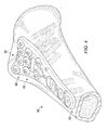
FIGURE 3A is a perspective view of an embodiment of the volar plate, showing the bone screws used to affix the plate to the bone fragments inserted into the distal head of the volar plate; -
FIGURE 3B is a second perspective view of an embodiment of the volar plate, rotated to show the underside of the plate; -
FIGURE 3C is a side view of an embodiment of the volar plate, with bone screws in place in the distal head of the volar plate; -
FIGURE 3D is a plan view of the underside of an embodiment of the volar plate, showing the bottom surface of the volar plate with bone screws in place to illustrate the configuration and orientation of the bone screws with respect to one another; -
FIGURE 4 is an illustrative perspective view of an exemplary volar plate held in place upon a distal volar radius bone in the wrist using a plurality of bone screws; -
FIGURE 5 is a plan view of an alternative embodiment of the volar plate, wherein the central cavity and the longitudinal screw slot have been joined; -
FIGURE 6 is a plan view of an alternative embodiment of the volar plate having an elongated proximal body portion; and -
FIGURE 7 is an illustrative perspective view showing a volar plate of the type shown inFIGURE 3A in which each of the K-wire holes of the distal head have axes substantially parallel to that of a corresponding bone screw hole and are visually linked with their corresponding bone screw holes. - Disclosed embodiments relate to surgically implanted internal fixation devices designed in accordance with anatomical studies. The disclosed embodiments comprise a volar plate designed for rigid attachment to the bone at the fracture site. Generally, the volar plate would be positioned on the volar side of a fractured radial bone, and would be held in place using bone screws anchored into the bone surface. Additionally, bone screws could be used to fix the position of bone fragments, stabilizing the wrist fracture.
-
FIGURE 1 generally demonstrates an embodiment of thevolar plate 10, illustrating the basic shape and features generally associated with the presentvolar plate 10, whileFIGURES 3A, 3B ,3C, and 3D further demonstrate the disclosed volar plate showing different views and bone screw placement. The volar plate ofFIGURE 1 employs a generally Y-shapedplate 10, with a widerdistal head portion 20 that tapers to a narrowerproximal body portion 15. Thedistal head 20 angles upward away from the plane of the generally flatproximal body portion 15 of the volar plate, forming a concaveupper surface 17. When thevolar plate 10 is in place on the bone, the bottom surface 18 (which is opposite the upper surface) of thevolar plate 10 would contact the bone. While thevolar plate 10 could be constructed of any surgically safe material sufficiently strong and rigid to support bone fragments, thevolar plate 10 ofFIGURE 1 is generally made of medical grade anodized titanium or stainless steel. - The Y-shaped
volar plate 10 may vary in size, allowing the surgeon the option to select thevolar plate 10 that best fits a particular patient. Typically, thevolar plate 10 of the embodiment shown inFIGURE 1 might range in width, having adistal head portion 20 from approximately 20mm to 30mm across. Likewise, the length of thevolar plate 10 might range from approximately 45mm to 100mm. Most commonly,volar plates 10 tend to be 50mm to 65mm in length. And in the embodiment ofFIGURE 3C , the angle between thedistal head 20 and theproximal body 15 is approximately twenty-five degrees. While specific disclosed embodiments may tend to have dimensions in the ranges discussed above, such dimensions are merely exemplary; a wide range of dimensions may be appropriate for thevolar plate 10, and all are intended to be included within the scope of this disclosure. - The shape of the
volar plate 10 is designed to mimic and mesh with the bone surface geometry of the distal radius, as illustrated inFIGURE 2 . The curvedupper surface 17 of the volar plate, resulting from the angled attachment of thedistal head portion 20 to theproximal body portion 15, mimics the curvature of the articular surface of the radius bone. Likewise, the Y-shape of theplate 10 allows for screw placement that essentially tracks the contours of the articular surface of the distal radius, basically following the subchondral bone contour line. The plate's shape provides anatomical alignment of thevolar plate 10 within the pronator quadratus fossa, allowing bone screws to obtain purchase in the dorsal subchondral bone without danger of protrusion into the wrist joint space. - A complicating factor in designing a
volar plate 10 based on anatomical modeling is that studies have shown that the volar surface geometry of the distal radius may not be standard, varying depending upon the individual. To account for this variance, allowing for more precise fitting of thevolar plate 10 during surgical implantation, a crease 60 (more clearly visible inFIGURE 3D ) may score thebottom surface 18 of the corner of thedistal head 20 of thevolar plate 10 relating to the radial styloid, allowing the doctor to more easily bend that corner of thedistal head portion 20 of thevolar plate 10 to adjust the fit based on a particular patient's bone geometry. Furthermore, the prominence of the lunate facet may be variable, such that alternative embodiments may utilize avolar plate 10 with a curved distal end, with varying degrees of curvature laterally across the distal end of the volar plate, providing a high contour plate designed to align with greater protrusions of the lunate facet or a low contour plate for patients with less curvature along the pronator quadratus line. Accordingly, the embodiment ofFIGURE 1 provides for avolar plate 10 designed to interact effectively with the patient's bone structure, thus providing a stable base of support for a wrist fracture. By utilizing an anatomically designedvolar plate 10, the risk of improper plate and screw placement is reduced, providing for successful, reproducible outcomes when mounting thevolar plate 10 on the bone. - The
distal head 20 of thevolar plate 10 forFIGURE 1 contains a plurality of threaded holes, through which bone screws (or some other fixation means) may be inserted to fix bone fragments in place relative to one another (as shown inFIGURE 3C ). While thevolar plate 10 provides the underlying support, forming a steady base for affixing bone fragments, the bone screws 90 that screw into the threaded holes in thedistal head 20 actually create the stabilization framework for the fracture. Generally, there are two rows of threaded screw holes located on thedistal head 20 of thevolar plate 10, and each of the holes are substantially the same size. - Each row of screw holes shown in
FIGURE 1 employs a substantially non-linear arrangement of holes, in an attempt to better match the contours of the wrist anatomy. Theproximal row 40 of thevolar plate 10 inFIGURE 1 has three threaded bone screw holes 41, 42, and 43 countersunk into theupper surface 17 of thevolar plate 10. Thevolar plate 10 ofFIGURE 1 utilizes a substantially non-linear alignment of theholes proximal row 40, with theinterior screw hole 42 distal to the two outside screw holes 41 and 43. Thus, in the embodiment ofFIGURE 1 the holes ofproximal row 40 are staggered to essentially form a non-linear arc. In the specific exemplary embodiment shown inFIGURE 1 , the non-linear arc of the holes of theproximal row 40 proceeds from a proximal position, to a distal position, and back to a proximal position (generally forming a substantially parabolic arc). Alternatively, theproximal row 40 could form a non-linear arc that proceeds from a distal position, to a proximal position, and back to a distal position. -
Distal row 50 ofFIGURE 1 has four threaded screw holes countersunk into theupper surface 17 of thevolar plate 10. Again, the holes of thedistal row 50 are arranged in a staggered, substantially non-linear alignment in an attempt to more closely match the contours of the distal radius, basically following the subchondral bone contour line in order to provide a stabilization framework that accommodates and interacts with the actual anatomy of the patient's wrist. So in the specific exemplary embodiment shown inFIGURE 1 , theinterior holes distal row 50 of screw holes would be located proximal to the two outer screw holes 51 and 54, such that the holes ofdistal row 50 essentially form a non-linear (often parabolic-shaped) arc curving in the opposite direction of the arc ofproximal row 40. In other words,distal row 50 curves from a distal position to a proximal position, and back to a distal position in the embodiment ofFIGURE 1 . Alternatively, the holes of thedistal row 50 could form a non-linear arc curving from a proximal position, to a distal position, and back to a proximal position. The non-linear orientation of the holes of the proximal and distal rows allows for a more organic design that may better interact with the underlying bone structure, such that the screws may track anatomical features and offer superior support. - The orientation of the screw holes (based on the angle at which the holes penetrate the
volar plate 10 and the angle at which the threads are set in the holes) determines the orientation of the bone screws 90 projecting out from the bottom surface of thehead 20 of thevolar plate 10.FIGURES 3A, 3B ,3C, and 3D illustrate one embodiment of thevolar plate 10 with the bone screws 90 in place (screwed into the threaded holes in the volar plate 10), showing the projection of the shafts of the bone screws 90 out thebottom surface 18 of thehead 20 of thevolar plate 10. When the bone screws 90 are inserted into the screw holes (41, 42, 43, 51, 52, 53, and 54) in thehead 20 of the volar plate 10 (by being screwed into theupper surface 17 of thevolar plate 10 and projecting out from thebottom surface 18 of the volar plate 10), thedistal row 50 of bone screws 90 would follow an angular orientation similar to the wrist joint surface, allowing thescrews 90 to reach and obtain purchase in subchondral bone without entering the joint space, while theproximal row 40 of bone screws 90 would substantially converge on thedistal row 50 ofscrews 90 to provide support while also possibly allowing the use of various screw lengths to accommodate various radius sizes, as necessary. Thus, the axes of the holes of the proximal row would substantially converge on the axes of the holes of the distal row, as both axes extend outward from the bottom surface of the volar plate. The term "converge" is intended here to describe the bone screws of the proximal row angling toward but not necessarily meeting or crossing the bone screws of the distal row in at least one plane. - In other words, the
screws 90 of theproximal row 40 would generally extend out between thescrews 90 of thedistal row 50. Thus, thescrews 90 of the distal and proximal rows would typically be interleaved, creating an effective stabilization framework for bone fragments. Such an alignment would allow for bone fragments to be engaged bybone screws 90 from multiple directions, so that the bone screws 90 might essentially cradle each bone fragment and provide an improved stabilization framework for supporting the fracture site. It also might allow multiple smaller fragments to be properly positioned, since a multitude of support axes would be available. And it might allow screws of various sizes to be used, such that longer screws typically required for larger radius sizes would not interfere with each other. - The
bone screw 90 alignment ofFIGURE 3D provides a detailed example. In the embodiment ofFIGURE 3D (as also shown inFIGURE 3A, 3B , and3C ), screws 90 in thedistal row 50 project outward from thebottom surface 18 at an angle that can vary from substantially perpendicular to tilting towards the proximal end as they extend outward. In addition, thescrews 90 may angle laterally as well. Theoutside screw 91 of thedistal row 50 angles towards the proximal end of thevolar plate 10, and may also simultaneously angle out away from thevolar plate 10 laterally. The inside screw 92 (of the distal row) next tooutside screw 91 angles towards the proximal end to a greater degree than doesoutside screw 91. The otherinside screw 93 angles towards the proximal end less than bothinside screw 92 andoutside screw 91. The radial styloid screw 94 (which is the other outside screw corresponding to the corner of thehead 20 of thevolar plate 10 with a crease 60) is adjustable based on the position to which the corner is bent when fitting thevolar plate 10 to the specific anatomical structure of the patient. The radialstyloid screw 94 projects out to be substantially perpendicular to thebottom surface 18 of that corner of thehead 20 of the volar plate10. Since the corner of thehead 20 of thevolar plate 10 with theradial styloid 94 is typically flexed upward (such that theupper surface 17 of that corner is concave), the radialstyloid screw 94 generally angles outward, allowing greater purchase of the typically larger radial styloid fragment. - In the embodiment shown in
FIGURE 3D , each of the bone screws 90 of thedistal row 50 tend to angle towards the proximal end within a range of angles from approximately six degrees to thirty-two degrees from normal. In addition, each of thescrews 90 of thedistal row 50 may angle laterally (in either lateral direction) within a range of angles between approximately zero degrees and ten degrees (as measured from a vertical center plane). These ranges are merely exemplary, however; any number ofbone screw 90 angles may be appropriate, and all are intended to be included within the scope of the disclosure. - The
screws 90 of theproximal row 40 inFIGURE 3D each angle towards the distal end of thevolar plate 10 as they extend outward, so that they converge on thescrews 90 of thedistal row 50. So asFIGURE 3D illustrates, each of the seven threaded screw holes of thevolar plate head 20 in this embodiment would generally be oriented so that the bone screws 90 inserted through them would project out in different directions, generally interleaving as the two rows converge. This provides for an effective stabilization framework, as bone fragments can be precisely held in the appropriate position in a manner that works with the underlying anatomical geometry of the distal radius. The precise bone screw placement described above forFIGURE 3D may vary, and different embodiments may use alternative placements. The general goal when placing bone screws 90 through avolar plate 10 is to provide an effective stabilization framework for fixing the bone fragments in proper alignment, preferably taking into account the anatomical geometry of the region. - The
volar plate 10 of the described embodiments also may contain acentral cavity 70, located generally in the vicinity of the region of thevolar plate 10 where thedistal head 20 angles away from theproximal body 15. By way of example,FIGURE 1 illustrates acentral cavity 70. Thecentral cavity 70 may promote bone growth by providing convenient access to proximal fracture sites for introduction of bone graft or bone void filler materials if needed during the treatment regimen. Furthermore, a plurality of mounting screw holes are located within theproximal body 15 of thevolar plate 10, allowing for the plate to be mounted in place securely on the bone. Generally, the mounting screws would extend through the mounting screw holes substantially perpendicular to thebottom surface 18 of thebody 15 of the volar plate. One or more mounting screw holes 31 are located towards the proximal end of the volar plate 10 (and one of these mounting screw holes could be configured as an elongated oval orslot 32, as shown inFIGURE 1 , allowing longitudinal movement of thevolar plate 10 with respect to the shaft of the mounting screws for adjustment as thevolar plate 10 is being affixed by the surgeon). These mounting screw holes allow thevolar plate 10 to be firmly fixed in place on the bone using bone screws, providing a secure foundation for the stabilization framework. And inFIGURE 1 , two additional mounting screw holes 33 are distal to the proximal mounting screw holes 31 and thelongitudinal slot 32, with one additional mountingscrew hole 33 on either side of thecentral opening 70. - These additional (distal) mounting screw holes 33 may provide for a more secure attachment of the
volar plate 10 to the patient's bone and/or allow fixation and support of more proximal fractures. Because of the placement of the two additional (distal) mounting screw holes 33 about thecentral cavity 70, thecentral cavity 70 ofFIGURE 1 is shaped to accommodate the screw placement by having a somewhat hourglass shape with a thinner waist in its middle. And given their distal position, it may be possible to utilize the additional (distal) mountingscrews 33 to provide further support to the fracture site, in addition to possibly serving as additional mounting locations for secure attachment of thevolar plate 10 to the bone. In this way, the distal mounting screw holes 33 may allow thevolar plate 10 to address a wider range of fracture locations. - It should be noted that in the embodiment of
FIGURE 1 , all of the bone screw holes in thedistal head 20, as well as the two distal mounting screws 33, are threaded. Utilizing threaded holes allows the bone screws 90 to be securely fastened to thevolar plate 10, such that they may then hold bone fragments in position with respect to thevolar plate 10. Thus, locking screws tend to be used in thedistal head 20. Mounting holes 31 (and the longitudinal slot 32) are not threaded inFIGURE 1 , since the mounting screws do not need to attach (with engaging threads) to thevolar plate 10, but can simply hold thevolar plate 10 in position against the bone. Thus, non-locking screws tend to be used in the body. Furthermore, all of the holes for the bone screws used with thevolar plate 10 are countersunk in the embodiment shown inFIGURE 1 . While this is not essential, it does provide a smootherupper surface 17, resulting in less irritation to the area surrounding thevolar plate 10. And bone screws, with threading substantially along the length of their shafts, seem to provide a more secure stabilization framework, since they obtain purchase in the bone fragments. - In the disclosed embodiment of
FIGURE 3C , locking bone screws 90 are generally used within thedistal head 20. The additional distal mounting screws (used within holes 33) may be either locking or non-locking, while the mounting screws (used withinholes 31 and 32) tend to be non-locking. In the embodiment ofFIGURE 3C , screws generally range from approximately 6mm to 28mm in length (depending upon the specific fracture situation). The diameter of the locking screws generally ranges from approximately 2mm to 2.7mm, while the non-locking screws (used for mounting thevolar plate 10 to the bone) tend to be approximately 3.5mm in diameter. These screw dimensions are only exemplary, however; a wide range of screws may be appropriate given the specific situation, and all are intended to be included within the scope of this disclosure. - Finally, the
volar plate 10 may include smaller holes for K-wires 80, allowing temporary fixation of thevolar plate 10 in place during the surgical procedure in such a way that the surgeon may correctly position and temporarily fix thevolar plate 10 prior to affixing it securely to the bone via bone screws. A plurality of K-wire holes 80 are positioned generally along thevolar plate 10 in such a way as to allow for effective temporary placement of the volar plate during the mounting procedure. - In practice, the
volar plate 10 would be mounted directly to the volar surface of the distal radius bone during a surgical operation for aligning and fixing bone fragments of a wrist fracture. By anatomically aligning thevolar plate 10 within the pronator quadratus fossa, the bone screws may obtain purchase in the dorsal subchondral bone without danger of protrusion into the joint. Thebottom face 18 of thevolar plate 10 would be placed in contact with the bone, with the surgeon positioning thevolar plate 10 as needed. Typically, thedistal head portion 20 of thevolar plate 10 would be placed over the bone fragments, so that bone screws 90 may be used to fix the position of the bone fragments. - Generally, K-wires would be inserted through the guide holes 80 to temporarily fix the
volar plate 10 onto the bone during the procedure and/or to provide an approximation of the projected axis of an adjacent screw position prior to actual insertion of the screw. The K-wires may also allow the surgeon to verify the approximate placement and angle that a screw may take in the bone. Since several of the K-wire holes 80 of the disclosed embodiment generally mimic the angle of nearby screw holes, the surgeon may preliminarily verify correct placement by examining the K-wire attachment to the bone via x-ray prior to drilling bone screw holes. The surgeon may then drill holes into the bone for the bone screws to enter and engage the bone. - For the exemplary embodiment of
FIGURE 1 , once thevolar plate 10 has been roughly positioned using K-wires, a bone screw would be inserted into thelongitudinal slot 32 and loosely tightened in place on the bone. Thevolar plate 10 would then be finally positioned (with adjustments being made longitudinally as needed by sliding the plate position based upon the location of the screw within the slot), and the bone screw inslot 32 would be tightened. The bone fragments would then generally be properly aligned, and bone screws 90 would be utilized to fix the position of the bone fragments. Finally, the remaining mounting screws would be inserted throughholes 31, firmly fixing thevolar plate 10 in place on the bone.FIGURE 4 illustrates an exemplaryvolar plate 10 fixed in position with respect to the volar surface of the distal radius bone, with bone screws securing the volar plate and fixing the position of bone fragments. -
FIGURES 5, 6, and 7 illustrate alternative embodiments of thevolar plate 10.FIGURE 5 , for example, employs acentral cavity 72, wherein the basiccentral cavity 70 ofFIGURE 1 would be physically linked with thelongitudinal mounting slot 32 ofFIGURE 1 to form an elongatedcentral cavity 72. This embodiment would allow maximum advantage from thecentral cavity 72, while also enhancing longitudinal adjustment capabilities.FIGURE 6 is similar, but theproximal body 15 is extended longitudinally, providing a longervolar plate 10 that can also accommodate shaft fractures. -
FIGURE 7 illustrates an embodiment in which the K-wire holes in thedistal head 20 of thevolar plate 10 are visually linked with their associated, corresponding bone screw holes. As described above, each of the seven threaded bone screw holes in thedistal head 20 of this embodiment of thevolar plate 10 project outward in different directions. It may be helpful for proper mounting if several of the K-wire holes in thedistal head 20 would project outward in the same general direction as specific corresponding bone screw holes, such that the center-line axis of each K-wire hole in the distal head would be substantially parallel to the center-line axis of the corresponding bone screw hole. This type of orientation would aid the surgeon in properly aligning bone fragments with K-wires prior to final fixation with bone screws. - In order to be most effective, however, the surgeon should be able to easily determine which K-wire hole is associated with a particular bone screw hole. By visually linking each K-wire hole to its corresponding bone screw hole in the
distal head 20 of thevolar plate 10, the surgeon would be able to simply identify which bone screw hole relates to a particular K-wire hole. By way of example, a geometrical marking (such as forming both the K-wire hole and the bone screw hole within the same indented area) or a graphical linking (such as a laser marking or a color coordinated marking system) could be used as the means for visually linking associated K-wire holes and bone screw holes. The example ofFIGURE 7 illustrates an embodiment of thevolar plate 10 in which K-wire hole 81 is visually linked withbone screw hole 52, while K-wire hole 82 is visually linked withbone screw hole 42. - While various embodiments in accordance with the principles disclosed herein have been described above, it should be understood that they have been presented by way of example only, and not limitation. Thus, the breadth and scope of the invention(s) should not be limited by any of the above-described exemplary embodiments, but should be defined only in accordance with any claims and their equivalents issuing from this disclosure. Furthermore, the above advantages and features are provided in described embodiments, but shall not limit the application of such issued claims to processes and structures accomplishing any or all of the above advantages.
- Additionally, the section headings herein are provided for consistency with the suggestions under 37 CFR 1.77 or otherwise to provide organizational cues. These headings shall not limit or characterize the invention(s) set out in any claims that may issue from this disclosure. Specifically and by way of example, although the headings refer to a "Field of the Invention," the claims should not be limited by the language chosen under this heading to describe the so-called field. Further, a description of a technology in the "Background of the Invention" is not to be construed as an admission that certain technology is prior art to any invention(s) in this disclosure. Neither is the "Brief Summary of the Invention" to be considered as a characterization of the invention(s) set forth in issued claims. Furthermore, any reference in this disclosure to "invention" in the singular should not be used to argue that there is only a single point of novelty in this disclosure. Multiple inventions may be set forth according to the limitations of the multiple claims issuing from this disclosure, and such claims accordingly define the invention(s), and their equivalents, that are protected thereby. In all instances, the scope of such claims shall be considered on their own merits in light of this disclosure, but should not be constrained by the headings set forth herein.
Claims (17)
- A volar plate (10) comprising:a substantially flat proximal body (15); anda distal head (20) coupled to the proximal body;wherein:the distal head (20) is wider than the proximal body (15);the distal head (20) angles upward away from the plane of the proximal body, forming a substantially concave upper surface (17);the distal head (20) comprises a plurality of holes formed therethrough;the plurality of holes are arranged in at least two rows, with a proximal row (40) of at least three holes (41, 42, 43) and a distal row (50) of at least three holes (51, 52, 53, 54);the holes (41, 42, 43) of the proximal row (40) are arranged substantially nonlinearly, and the holes (51, 52, 53, 54) of the distal row (50) are arranged substantially nonlinearly;the distal row (50) includes one or more interior holes (52, 53) and two outside holes (51, 54), the one or more interior holes (52, 53) being proximal to the two outside holes (51, 54);the holes of the distal row (50) are all located more distal from the proximal body than all of the holes of the proximal row; andthe proximal row (40) of holes forms a substantially parabolic arc, with the location of the holes of the proximal row proceeding from a proximal position, to a distal position, to a proximal position.
- A volar plate as in claim 1, further comprising one or more K-wire holes (80) in the distal head (20) of the volar plate, wherein:each K-wire hole (80) corresponds to one of the plurality of holes in the distal head of the volar plate, with the center-line axis of each K-wire hole substantially parallel to the center-line axis of its corresponding hole in the distal head; andeach K-wire hole (80) is visually linked to its corresponding hole in the distal head.
- A volar plate as in claim 1 further comprising a central cavity (70, 72), wherein the central cavity is disposed substantially towards the distal end of the proximal body (15).
- A volar plate as in claim 3 further comprising two mounting screw holes (30), wherein one mounting screw hole (33) is located laterally on either side of the central cavity (70).
- A volar plate as in claim 1, wherein the proximal row (40) includes one or more interior holes (42) and two outside holes (41, 43), the one or more interior holes (42) being distal to the two outside holes (41, 43).
- A volar plate as in claim 1, wherein the distal row of holes (50) forms a substantially non-linear arc, with the location of the holes of the distal row proceeding from a distal position, to a proximal position, to a distal position.
- A volar plate as in claim 6, wherein the proximal row (40) includes one or more interior holes (42) and two outside holes (41, 43), the one or more interior holes (42) of the proximal row being distal to the two outside holes (41, 43) of the proximal row.
- A volar plate as in claim 7 further comprising a bottom surface (18), wherein the plurality of holes in the distal head (20) of the volar plate are oriented so that the axes of the holes (51, 52, 53, 54) in the distal row (50) project outward from the bottom surface (18) angling proximally within a range of angles from approximately 6 to 32 degrees from normal, and the axes of the holes (41, 42, 43) in the proximal row (40) project outward from the bottom surface (18) and substantially converge on the axes of the holes of the distal row as both axes project outward from the bottom surface of the volar plate.
- A volar plate as in claim 7, wherein the volar plate is substantially Y-shaped.
- A volar plate as in claim 7 further comprising a crease (60) along the bottom surface of one outside corner of the distal head (20).
- A fixation device comprising a volar plate as in any preceding claim, and a plurality of bone screws (90) with threaded shafts, wherein the plurality of holes in the distal head are threaded, and the plurality of bone screws penetrate and threadably engage the distal head (20) through the plurality of threaded holes, such that the shafts of the bone screws project outward away from a bottom surface (18) of the volar plate.
- A fixation device as claim 11, wherein:the bottom surface (18) of the volar plate is operable to be placed in contact with a radius bone's volar surface proximal to a wrist joint; andthe plurality of holes (41, 42, 43; 51, 52, 53, 54) in the distal head of the volar plate are oriented so that the shafts of the bone screws (90) projecting out from the holes (51, 52, 53, 54) of the distal row (50) extend out away from the bottom surface of the volar plate and are generally aligned with the joint surface so as to obtain purchase in the bone's subchondral layer, and the shafts of the bone screws (90) projecting out from the holes (41, 42, 43) of the proximal row (40) substantially converge on the shafts of the bone screws from the distal row.
- A volar plate as in claim 1, wherein the distal row (50) of holes (51, 52, 53, 54) curves to substantially track the subchondral bone contour line of a distal radius bone.
- A fixation device comprising a volar plate as in claim 1 and a plurality of bone screws (90) with threaded shafts, wherein:the volar plate comprises a bottom surface (18) operable to be placed in contact with a radius bone's volar surface proximal to a wrist joint;the plurality of bone screws penetrate and threadably engage the volar plate through the plurality of threaded holes, such that the shafts of the bone screws project outward away from the bottom surface of the volar plate; andthe plurality of holes in the distal head of the volar plate are oriented so that the shafts of the bone screws projecting out from the holes of the distal row extend out away from the bottom surface of the volar plate and are generally aligned with the joint surface so as to be operable to obtain purchase in the bone's subchondral layer, and the shafts of the bone screws projecting out from the holes of the proximal row substantially converge on the shafts of the bone screws from the distal row.
- A volar plate as in claim 1, or claim 7, or claim 9, or claim 13, further comprising one or more K-wire holes (80) in the distal head (20) of the volar plate, wherein:each K-wire hole (80) corresponds to one of the plurality of threaded holes in the distal head of the volar plate, with the center-line axis of each K-wire hole substantially parallel to the center-line axis of its corresponding threaded hole in the distal head; andeach K-wire hole (80) is connected to its corresponding threaded hole in the distal head by a graphical link in the surface of the volar plate.
- A volar plate as in claim 1 or a fixation device as in claim 11, wherein the proximal and distal rows of threaded holes are transverse to a longitudinal axis of the volar plate and the non-linear arrangement of the rows is defined by the displacement of each threaded hole along the longitudinal axis of the volar plate.
- A volar plate as in claim 1 or a fixation device as in claim 11, wherein the distal head comprises a crease along the bottom surface of one outside corner.
Applications Claiming Priority (2)
| Application Number | Priority Date | Filing Date | Title |
|---|---|---|---|
| US11/567,661 US8398687B2 (en) | 2006-12-06 | 2006-12-06 | Volar plate fixation device |
| PCT/US2007/086450 WO2008070695A2 (en) | 2006-12-06 | 2007-12-05 | Volar plate fixation device |
Publications (3)
| Publication Number | Publication Date |
|---|---|
| EP2099373A2 EP2099373A2 (en) | 2009-09-16 |
| EP2099373A4 EP2099373A4 (en) | 2012-07-18 |
| EP2099373B1 true EP2099373B1 (en) | 2014-10-22 |
Family
ID=39493045
Family Applications (1)
| Application Number | Title | Priority Date | Filing Date |
|---|---|---|---|
| EP07854942.5A Active EP2099373B1 (en) | 2006-12-06 | 2007-12-05 | Volar plate fixation device |
Country Status (6)
| Country | Link |
|---|---|
| US (1) | US8398687B2 (en) |
| EP (1) | EP2099373B1 (en) |
| AR (1) | AR064600A1 (en) |
| AU (1) | AU2007329398B2 (en) |
| ES (1) | ES2528203T3 (en) |
| WO (1) | WO2008070695A2 (en) |
Cited By (1)
| Publication number | Priority date | Publication date | Assignee | Title |
|---|---|---|---|---|
| US12408956B2 (en) | 2023-02-21 | 2025-09-09 | DePuy Synthes Products, Inc. | Bone plates, and related systems and methods |
Families Citing this family (47)
| Publication number | Priority date | Publication date | Assignee | Title |
|---|---|---|---|---|
| US9283010B2 (en) * | 2008-05-05 | 2016-03-15 | Trimed, Incorporated | Contoured bone plate for fracture fixation having hook members and holder/impactor for same |
| US8419735B2 (en) * | 2009-05-05 | 2013-04-16 | Synthes Usa, Llc | Nail locking systems |
| JP2013512042A (en) * | 2009-11-27 | 2013-04-11 | シンセス ゲゼルシャフト ミット ベシュレンクテル ハフツング | Planar fixation concept for distal radius fractures |
| FR2956971B1 (en) | 2010-03-08 | 2012-03-02 | Memometal Technologies | PLATE OSTEOSYNTHESIS SYSTEM |
| FR2956972B1 (en) | 2010-03-08 | 2012-12-28 | Memometal Technologies | ARTICULATED OSTEOSYNTHESIS PLATE |
| US8603148B2 (en) * | 2010-05-07 | 2013-12-10 | Raymond B. Raven, III | System for treating bone fractures |
| KR101219266B1 (en) * | 2010-08-13 | 2013-01-18 | 박지선 | Lesser Trochanter Fixation Apparatus For The Stable Replacement Of The Artificial Hip Joint By Rigid Fixation Around Of The Femoral Lesser Trochanter Fractures |
| WO2012050424A1 (en) * | 2010-10-14 | 2012-04-19 | Sai Yeong Leong | A distal radius plating system |
| US8518042B2 (en) * | 2010-10-19 | 2013-08-27 | Biomet Manufacturing, Llc | Orthopedic plate assembly for a distal radius having re-contouring features and method for using same |
| DE102010052231A1 (en) * | 2010-11-24 | 2012-05-24 | Normed Medizin-Technik Gmbh | Medical implant |
| US8790378B2 (en) | 2012-02-02 | 2014-07-29 | Biomet C.V. | Distal radius fracture fixation plate with integrated and adjustable volar ulnar facet support |
| EP2872073B1 (en) | 2012-07-12 | 2018-09-19 | Exsomed Holding Company LLC | Metacarpal bone stabilization device |
| EP2730244B1 (en) | 2012-11-07 | 2017-04-26 | Arthrex, Inc. | Bone plate with suture holes for soft tissue reattachment on the diaphyseal region of the plate |
| US9545276B2 (en) * | 2013-03-15 | 2017-01-17 | Aristotech Industries Gmbh | Fixation device and method of use for a lapidus-type plantar hallux valgus procedure |
| US11259849B2 (en) | 2013-10-02 | 2022-03-01 | ExsoMed Corporation | Full wrist fusion device |
| WO2015088760A1 (en) * | 2013-12-11 | 2015-06-18 | DePuy Synthes Products, LLC | Bone plate |
| US9848924B2 (en) | 2013-12-11 | 2017-12-26 | DePuy Synthes Products, Inc. | Bone plate |
| FR3023469B1 (en) * | 2014-07-10 | 2016-08-26 | In2Bones | IMPLANT AND SURGICAL KIT FOR MAINTAINING THE BONE BODIES OF A PATIENT IN RELATION TO OTHERS |
| US9730686B2 (en) | 2014-09-03 | 2017-08-15 | Biomet C.V. | System and method of soft tissue anchoring to metaphyseal bone plate |
| JP6936146B2 (en) | 2015-01-07 | 2021-09-15 | トリース メディカル コンセプツ,インコーポレイティド | Bone plate fixation system and method |
| US10245086B2 (en) | 2015-02-18 | 2019-04-02 | Treace Medical Concepts, Inc. | Bone plating kit for foot and ankle applications |
| US20160278824A1 (en) * | 2015-03-25 | 2016-09-29 | Medartis Holding Ag | Method for treating fractures of a bone |
| WO2016186847A1 (en) * | 2015-05-19 | 2016-11-24 | Exsomed International IP, LLC | Distal radius plate |
| US10245091B2 (en) | 2015-12-30 | 2019-04-02 | Exsomed Holding Company, Llc | Dip fusion spike screw |
| US11147604B2 (en) | 2016-01-12 | 2021-10-19 | ExsoMed Corporation | Bone stabilization device |
| USD787060S1 (en) * | 2016-02-17 | 2017-05-16 | Karl Leibinger Medizintechnik Gmbh & Co. Kg | Jawbone implant |
| USD785798S1 (en) * | 2016-02-17 | 2017-05-02 | Karl Leibinger Medizintechnik Gmbh & Co. Kg | Jawbone implant |
| USD785178S1 (en) * | 2016-02-17 | 2017-04-25 | Karl Leibinger Medizintechnik Gmbh & Co. Kg | Zygomatic bone implant |
| USD787058S1 (en) * | 2016-02-17 | 2017-05-16 | Karl Leibinger Medizintechnik Gmbh & Co. Kg | Eye-socket implant |
| USD786436S1 (en) * | 2016-02-17 | 2017-05-09 | Karl Leibinger Medizintechnik Gmbh & Co. Kg | Cheekbone implant |
| USD787059S1 (en) * | 2016-02-17 | 2017-05-16 | Karl Leibinger Medzintechnik GmbH & Co. KG | Jawbone implant |
| USD786435S1 (en) * | 2016-02-17 | 2017-05-09 | Karl Leibinger Medizintechnik Gmbh & Co. Kg | Jawbone implant |
| US9956437B2 (en) * | 2016-03-18 | 2018-05-01 | Fire Innovations Llc | Auto brake hand descent control device |
| US10112062B2 (en) * | 2016-03-18 | 2018-10-30 | Fire Innovations Llc | Auto brake hand descent control device |
| US10194923B2 (en) | 2016-05-10 | 2019-02-05 | Exsomed International IP, LLC | Tool for percutaneous joint cartilage destruction and preparation for joint fusion |
| USD869657S1 (en) * | 2017-07-31 | 2019-12-10 | Crossroads Extremity Systems, Llc | Bone plate |
| US11191645B2 (en) | 2017-09-05 | 2021-12-07 | ExsoMed Corporation | Small bone tapered compression screw |
| US11147681B2 (en) | 2017-09-05 | 2021-10-19 | ExsoMed Corporation | Small bone angled compression screw |
| EP4477166A3 (en) | 2017-09-05 | 2025-03-19 | ExsoMed Corporation | Intramedullary threaded nail for radial cortical fixation |
| AU2018346398B2 (en) | 2017-10-06 | 2024-05-16 | Mullin Patents, Llc | Spinal implant |
| CA3086369A1 (en) | 2017-12-20 | 2019-06-27 | Glenhurst Labs, Llc | Multiplanar fixation plate for fracture repair |
| WO2020014660A1 (en) | 2018-07-12 | 2020-01-16 | Treace Medical Concepts, Inc. | Multi-diameter bone pin for installing and aligning bone fixation plate while minimizing bone damage |
| USD874004S1 (en) * | 2018-09-26 | 2020-01-28 | Paragon 28, Inc. | Bone plate |
| USD874650S1 (en) * | 2018-10-23 | 2020-02-04 | DePuy Synthes Products, Inc. | Distal femur plate |
| US11877719B2 (en) * | 2019-06-25 | 2024-01-23 | OrthoNovis, Inc. | Bone plate with orientation indicator and positional adjustment mechanism |
| US11890039B1 (en) | 2019-09-13 | 2024-02-06 | Treace Medical Concepts, Inc. | Multi-diameter K-wire for orthopedic applications |
| US20240050230A1 (en) * | 2022-08-12 | 2024-02-15 | Stryker European Operations Limited | Bone Plate With Tamp Window For Tibia Plateau Fracture |
Family Cites Families (76)
| Publication number | Priority date | Publication date | Assignee | Title |
|---|---|---|---|---|
| AT378324B (en) | 1982-09-13 | 1985-07-25 | Streli Elke | TINNED PLATE FOR FIXING THE BONES IN THE BODIES IN BONE BREAKS |
| US5190544A (en) | 1986-06-23 | 1993-03-02 | Pfizer Hospital Products Group, Inc. | Modular femoral fixation system |
| US4776330A (en) | 1986-06-23 | 1988-10-11 | Pfizer Hospital Products Group, Inc. | Modular femoral fixation system |
| US4905679A (en) | 1988-02-22 | 1990-03-06 | M P Operation, Inc. | Bone fracture reduction device and method of internal fixation of bone fractures |
| US4955886A (en) | 1988-04-01 | 1990-09-11 | The Trustees Of Columbia University In The City Of New York | Dual-taper, asymmetric hole placement in reconstruction and fracture plates |
| US5006120A (en) | 1989-10-10 | 1991-04-09 | Carter Peter R | Distal radial fracture set and method for repairing distal radial fractures |
| US5015248A (en) | 1990-06-11 | 1991-05-14 | New York Society For The Relief Of The Ruptured & Crippled, Maintaining The Hospital For Special Surgery | Bone fracture fixation device |
| US5085660A (en) | 1990-11-19 | 1992-02-04 | Lin Kwan C | Innovative locking plate system |
| US5304180A (en) | 1992-01-17 | 1994-04-19 | Slocum D Barclay | Tibial osteotomy fixation plate |
| US5197966A (en) | 1992-05-22 | 1993-03-30 | Sommerkamp T Greg | Radiodorsal buttress blade plate implant for repairing distal radius fractures |
| IL105183A (en) | 1993-03-28 | 1996-07-23 | Yehiel Gotfried | Surgical device for connection of fractured bones |
| SE501265C2 (en) | 1993-05-07 | 1994-12-19 | Elos Ind Ab | Device for fixing vertebrae |
| DE4343117C2 (en) | 1993-12-17 | 1999-11-04 | Dietmar Wolter | Bone fixation system |
| US5591169A (en) | 1994-06-14 | 1997-01-07 | Benoist; Louis | Device and method for positioning and holding bone fragments in place |
| US5601553A (en) | 1994-10-03 | 1997-02-11 | Synthes (U.S.A.) | Locking plate and bone screw |
| US5586985A (en) | 1994-10-26 | 1996-12-24 | Regents Of The University Of Minnesota | Method and apparatus for fixation of distal radius fractures |
| SE505452C2 (en) | 1995-02-14 | 1997-09-01 | Robert J Medoff | An implantable fragment clip / support and method of making it |
| SE508120C2 (en) | 1995-01-27 | 1998-08-31 | Robert J Medoff | Implantable device comprising a pin plate and pins |
| US5941878A (en) | 1995-02-14 | 1999-08-24 | Medoff; Robert J. | Implantable, surgical buttressing device |
| SE505453C2 (en) | 1995-02-14 | 1997-09-01 | Robert J Medoff | Implantable support plate |
| WO1996029948A1 (en) | 1995-03-27 | 1996-10-03 | Synthes Ag, Chur | Bone plate |
| US5749872A (en) * | 1995-09-08 | 1998-05-12 | Ace Medical Company | Keyed/keyless barrel for bone plates |
| US5868749A (en) | 1996-04-05 | 1999-02-09 | Reed; Thomas M. | Fixation devices |
| SE510025C2 (en) | 1996-05-10 | 1999-04-12 | Robert J Medoff | Graft material retaining device |
| US6096040A (en) * | 1996-06-14 | 2000-08-01 | Depuy Ace Medical Company | Upper extremity bone plates |
| US5827286A (en) | 1997-02-14 | 1998-10-27 | Incavo; Stephen J. | Incrementally adjustable tibial osteotomy fixation device and method |
| US5853413A (en) | 1997-04-18 | 1998-12-29 | Bristol-Myers Squibb Company | Wrist fusion plate |
| ZA983955B (en) | 1997-05-15 | 2001-08-13 | Sdgi Holdings Inc | Anterior cervical plating system. |
| US6030389A (en) | 1997-08-04 | 2000-02-29 | Spinal Concepts, Inc. | System and method for stabilizing the human spine with a bone plate |
| US6129728A (en) | 1998-02-18 | 2000-10-10 | Walter Lorenz Surgical, Inc. | Method and apparatus for mandibular osteosynthesis |
| US5938664A (en) | 1998-03-31 | 1999-08-17 | Zimmer, Inc. | Orthopaedic bone plate |
| US6228085B1 (en) | 1998-07-14 | 2001-05-08 | Theken Surgical Llc | Bone fixation system |
| SE9900094D0 (en) | 1999-01-15 | 1999-01-15 | Robert J Medoff | A method of enabling bone screws to be installed at an angle in underlying bone |
| US6129730A (en) | 1999-02-10 | 2000-10-10 | Depuy Acromed, Inc. | Bi-fed offset pitch bone screw |
| US6221073B1 (en) | 1999-08-20 | 2001-04-24 | Kinetikos Medical, Inc. | Wrist fusion apparatus and method |
| ES2211583T3 (en) * | 1999-09-13 | 2004-07-16 | Synthes Ag Chur | OSEA PLATE SYSTEM. |
| US6440135B2 (en) | 2000-02-01 | 2002-08-27 | Hand Innovations, Inc. | Volar fixation system with articulating stabilization pegs |
| US6712820B2 (en) | 2000-02-01 | 2004-03-30 | Hand Innovations, Inc. | Fixation plate system for dorsal wrist fracture fixation |
| US6767351B2 (en) | 2000-02-01 | 2004-07-27 | Hand Innovations, Inc. | Fixation system with multidirectional stabilization pegs |
| US6866665B2 (en) | 2003-03-27 | 2005-03-15 | Hand Innovations, Llc | Bone fracture fixation system with subchondral and articular surface support |
| US6358250B1 (en) | 2000-02-01 | 2002-03-19 | Hand Innovations, Inc. | Volar fixation system |
| US6893444B2 (en) | 2000-02-01 | 2005-05-17 | Hand Innovations, Llc | Bone fracture fixation systems with both multidirectional and unidirectional stabilization pegs |
| US6283969B1 (en) | 2000-03-10 | 2001-09-04 | Wright Medical Technology, Inc. | Bone plating system |
| USD443060S1 (en) | 2000-06-01 | 2001-05-29 | Bristol-Myers Squibb Company | Bone plate |
| US20020156474A1 (en) | 2001-04-20 | 2002-10-24 | Michael Wack | Polyaxial locking plate |
| US20050049594A1 (en) * | 2001-04-20 | 2005-03-03 | Wack Michael A. | Dual locking plate and associated method |
| US20050234458A1 (en) * | 2004-04-19 | 2005-10-20 | Huebner Randall J | Expanded stabilization of bones |
| US20050240187A1 (en) * | 2004-04-22 | 2005-10-27 | Huebner Randall J | Expanded fixation of bones |
| SI1389963T1 (en) * | 2001-05-28 | 2006-10-31 | Synthes Ag | Bone plate for the fixation of fractures of the proximal humerus |
| US6508819B1 (en) | 2001-08-28 | 2003-01-21 | Hand Innovations, Inc. | Method of dorsal wrist fracture fixation |
| US6652530B2 (en) | 2001-09-19 | 2003-11-25 | The University Of Hong Kong | Fixation device |
| US6755831B2 (en) | 2001-11-30 | 2004-06-29 | Regents Of The University Of Minnesota | Wrist surgery devices and techniques |
| USD469533S1 (en) | 2002-01-17 | 2003-01-28 | Zimmer, Inc. | Orthopaedic bone plate |
| US20030153918A1 (en) | 2002-02-14 | 2003-08-14 | Putnam Matthew D. | Volar fixation plate |
| USD469874S1 (en) | 2002-04-26 | 2003-02-04 | Zimmer, Inc. | Orthopaedic bone plate |
| KR101081269B1 (en) * | 2002-11-19 | 2011-11-08 | 어큠드 엘엘씨 | Adjustable pattern plate |
| US7294130B2 (en) * | 2003-03-27 | 2007-11-13 | Depuy Products, Inc. | Distal radius fracture fixation plate having K-wire hole structured to fix a K-wire in one dimension relative to the plate |
| US20040193155A1 (en) | 2003-03-27 | 2004-09-30 | Hand Innovations, Inc. | Fracture fixation plate with particular plate hole and fastener engagement and methods of using the same |
| US7635381B2 (en) * | 2003-03-27 | 2009-12-22 | Depuy Products, Inc. | Anatomical distal radius fracture fixation plate with fixed-angle K-wire holes defining a three-dimensional surface |
| US7250053B2 (en) * | 2003-03-27 | 2007-07-31 | Depuy Products, Inc. | Low profile distal radius fracture fixation plate |
| EP1464295A3 (en) * | 2003-04-01 | 2006-04-26 | Zimmer GmbH | Implant |
| CN100475168C (en) * | 2003-09-08 | 2009-04-08 | 斯恩蒂斯有限公司 | Bone-fixation device |
| US7269658B2 (en) | 2003-10-16 | 2007-09-11 | Lucent Technologies Inc. | Method and system for connecting calls through virtual media gateways |
| WO2005037114A1 (en) * | 2003-10-17 | 2005-04-28 | Acumed Llc | Systems for distal radius fixation |
| WO2005046494A1 (en) | 2003-10-17 | 2005-05-26 | Acumed Llc | Bone plates with slots |
| JP4790634B2 (en) * | 2004-01-23 | 2011-10-12 | デピュイ・プロダクツ・インコーポレイテッド | System for fixing fractures of convex articular bone surfaces having a subchondral support structure |
| US7572282B2 (en) * | 2004-04-23 | 2009-08-11 | Depuy Spine Sarl | Spinal fixation plates and plate extensions |
| US20060089648A1 (en) * | 2004-10-27 | 2006-04-27 | Masini Michael A | Versatile bone plate systems particularly suited to minimally invasive surgical procedures |
| US8062296B2 (en) | 2005-03-17 | 2011-11-22 | Depuy Products, Inc. | Modular fracture fixation plate system with multiple metaphyseal and diaphyseal plates |
| US7771433B2 (en) | 2004-12-14 | 2010-08-10 | Depuy Products, Inc. | Bone fracture fixation plate shaping system |
| US8172886B2 (en) | 2004-12-14 | 2012-05-08 | Depuy Products, Inc. | Bone plate with pre-assembled drill guide tips |
| DE602005004375T2 (en) | 2005-03-11 | 2009-01-22 | Orthofix S.R.L., Bussolengo | Device for osteosynthesis of proximal humerus fractures |
| FI119969B (en) * | 2005-05-06 | 2009-05-29 | Inion Ltd | Plate and system for attaching leg parts |
| US20060264947A1 (en) * | 2005-05-20 | 2006-11-23 | Orbay Jorge L | Bone fixation system |
| US8808334B2 (en) * | 2006-03-07 | 2014-08-19 | Orthohelix Surgical Designs, Inc. | Orthopedic plate |
| US8926675B2 (en) * | 2006-04-11 | 2015-01-06 | Biomet Manufacturing, Llc | Contoured bone plate |
-
2006
- 2006-12-06 US US11/567,661 patent/US8398687B2/en active Active
-
2007
- 2007-12-05 AU AU2007329398A patent/AU2007329398B2/en not_active Ceased
- 2007-12-05 EP EP07854942.5A patent/EP2099373B1/en active Active
- 2007-12-05 WO PCT/US2007/086450 patent/WO2008070695A2/en not_active Ceased
- 2007-12-05 ES ES07854942.5T patent/ES2528203T3/en active Active
- 2007-12-06 AR ARP070105478A patent/AR064600A1/en not_active Application Discontinuation
Cited By (1)
| Publication number | Priority date | Publication date | Assignee | Title |
|---|---|---|---|---|
| US12408956B2 (en) | 2023-02-21 | 2025-09-09 | DePuy Synthes Products, Inc. | Bone plates, and related systems and methods |
Also Published As
| Publication number | Publication date |
|---|---|
| WO2008070695A3 (en) | 2008-07-31 |
| EP2099373A2 (en) | 2009-09-16 |
| ES2528203T3 (en) | 2015-02-05 |
| WO2008070695A2 (en) | 2008-06-12 |
| AR064600A1 (en) | 2009-04-15 |
| AU2007329398A1 (en) | 2008-06-12 |
| US8398687B2 (en) | 2013-03-19 |
| AU2007329398B2 (en) | 2013-06-20 |
| US20080140127A1 (en) | 2008-06-12 |
| EP2099373A4 (en) | 2012-07-18 |
Similar Documents
| Publication | Publication Date | Title |
|---|---|---|
| AU2007329398B2 (en) | Volar plate fixation device | |
| KR101144067B1 (en) | Anatomical distal radius fracture fixation plate and methods of using the same | |
| EP1605842B1 (en) | Bone fracture fixation system with subchondral and articular surface support | |
| JP4421474B2 (en) | Intramedullary fixation device for long bone metaphyseal fractures | |
| US7563263B2 (en) | Intramedullary fixation device for metaphyseal long bone fractures | |
| US9370386B2 (en) | Plating concept for distal radial fractures | |
| US6730090B2 (en) | Fixation device for metaphyseal long bone fractures | |
| US8556945B2 (en) | Anatomical distal radius fracture fixation plate with ulnar buttress | |
| US11583317B2 (en) | Acromioclavicular hook plate | |
| US20160166297A1 (en) | Bone plate with elevated suture hole structures | |
| KR20020081282A (en) | Volar fixation system | |
| EP2675378A2 (en) | Fracture fixation plate | |
| EP2040631A2 (en) | Calcaneal plate | |
| US12023078B2 (en) | Distal radius plating system | |
| CN111867504A (en) | Multiplanar fixation plate for fracture repair | |
| JP7532499B2 (en) | Acromion Fracture Repair System | |
| US20120016366A1 (en) | Proximal Radius Locking Plate | |
| RU216558U1 (en) | DEVICE FOR OSTEOSYNTHESIS OF UNSTABLE FRACTURES OF THE PROXIMAL TIBIRAL METAPHIPHYSIS |
Legal Events
| Date | Code | Title | Description |
|---|---|---|---|
| PUAI | Public reference made under article 153(3) epc to a published international application that has entered the european phase |
Free format text: ORIGINAL CODE: 0009012 |
|
| 17P | Request for examination filed |
Effective date: 20090608 |
|
| AK | Designated contracting states |
Kind code of ref document: A2 Designated state(s): AT BE BG CH CY CZ DE DK EE ES FI FR GB GR HU IE IS IT LI LT LU LV MC MT NL PL PT RO SE SI SK TR |
|
| DAX | Request for extension of the european patent (deleted) | ||
| A4 | Supplementary search report drawn up and despatched |
Effective date: 20120619 |
|
| RIC1 | Information provided on ipc code assigned before grant |
Ipc: A61B 17/80 20060101AFI20120613BHEP |
|
| 17Q | First examination report despatched |
Effective date: 20130409 |
|
| REG | Reference to a national code |
Ref country code: DE Ref legal event code: R079 Ref document number: 602007039004 Country of ref document: DE Free format text: PREVIOUS MAIN CLASS: A61B0017580000 Ipc: A61B0019000000 |
|
| GRAP | Despatch of communication of intention to grant a patent |
Free format text: ORIGINAL CODE: EPIDOSNIGR1 |
|
| RIC1 | Information provided on ipc code assigned before grant |
Ipc: A61B 17/80 20060101ALI20140505BHEP Ipc: A61B 19/00 20060101AFI20140505BHEP |
|
| INTG | Intention to grant announced |
Effective date: 20140522 |
|
| GRAS | Grant fee paid |
Free format text: ORIGINAL CODE: EPIDOSNIGR3 |
|
| GRAA | (expected) grant |
Free format text: ORIGINAL CODE: 0009210 |
|
| AK | Designated contracting states |
Kind code of ref document: B1 Designated state(s): AT BE BG CH CY CZ DE DK EE ES FI FR GB GR HU IE IS IT LI LT LU LV MC MT NL PL PT RO SE SI SK TR |
|
| REG | Reference to a national code |
Ref country code: GB Ref legal event code: FG4D |
|
| REG | Reference to a national code |
Ref country code: CH Ref legal event code: EP |
|
| REG | Reference to a national code |
Ref country code: AT Ref legal event code: REF Ref document number: 692227 Country of ref document: AT Kind code of ref document: T Effective date: 20141115 |
|
| REG | Reference to a national code |
Ref country code: IE Ref legal event code: FG4D |
|
| REG | Reference to a national code |
Ref country code: DE Ref legal event code: R096 Ref document number: 602007039004 Country of ref document: DE Effective date: 20141204 |
|
| REG | Reference to a national code |
Ref country code: ES Ref legal event code: FG2A Ref document number: 2528203 Country of ref document: ES Kind code of ref document: T3 Effective date: 20150205 |
|
| REG | Reference to a national code |
Ref country code: NL Ref legal event code: VDEP Effective date: 20141022 |
|
| REG | Reference to a national code |
Ref country code: AT Ref legal event code: MK05 Ref document number: 692227 Country of ref document: AT Kind code of ref document: T Effective date: 20141022 |
|
| REG | Reference to a national code |
Ref country code: LT Ref legal event code: MG4D |
|
| PG25 | Lapsed in a contracting state [announced via postgrant information from national office to epo] |
Ref country code: IS Free format text: LAPSE BECAUSE OF FAILURE TO SUBMIT A TRANSLATION OF THE DESCRIPTION OR TO PAY THE FEE WITHIN THE PRESCRIBED TIME-LIMIT Effective date: 20150222 Ref country code: NL Free format text: LAPSE BECAUSE OF FAILURE TO SUBMIT A TRANSLATION OF THE DESCRIPTION OR TO PAY THE FEE WITHIN THE PRESCRIBED TIME-LIMIT Effective date: 20141022 Ref country code: PT Free format text: LAPSE BECAUSE OF FAILURE TO SUBMIT A TRANSLATION OF THE DESCRIPTION OR TO PAY THE FEE WITHIN THE PRESCRIBED TIME-LIMIT Effective date: 20150223 Ref country code: LT Free format text: LAPSE BECAUSE OF FAILURE TO SUBMIT A TRANSLATION OF THE DESCRIPTION OR TO PAY THE FEE WITHIN THE PRESCRIBED TIME-LIMIT Effective date: 20141022 Ref country code: FI Free format text: LAPSE BECAUSE OF FAILURE TO SUBMIT A TRANSLATION OF THE DESCRIPTION OR TO PAY THE FEE WITHIN THE PRESCRIBED TIME-LIMIT Effective date: 20141022 |
|
| PG25 | Lapsed in a contracting state [announced via postgrant information from national office to epo] |
Ref country code: PL Free format text: LAPSE BECAUSE OF FAILURE TO SUBMIT A TRANSLATION OF THE DESCRIPTION OR TO PAY THE FEE WITHIN THE PRESCRIBED TIME-LIMIT Effective date: 20141022 Ref country code: SE Free format text: LAPSE BECAUSE OF FAILURE TO SUBMIT A TRANSLATION OF THE DESCRIPTION OR TO PAY THE FEE WITHIN THE PRESCRIBED TIME-LIMIT Effective date: 20141022 Ref country code: GR Free format text: LAPSE BECAUSE OF FAILURE TO SUBMIT A TRANSLATION OF THE DESCRIPTION OR TO PAY THE FEE WITHIN THE PRESCRIBED TIME-LIMIT Effective date: 20150123 Ref country code: AT Free format text: LAPSE BECAUSE OF FAILURE TO SUBMIT A TRANSLATION OF THE DESCRIPTION OR TO PAY THE FEE WITHIN THE PRESCRIBED TIME-LIMIT Effective date: 20141022 Ref country code: LV Free format text: LAPSE BECAUSE OF FAILURE TO SUBMIT A TRANSLATION OF THE DESCRIPTION OR TO PAY THE FEE WITHIN THE PRESCRIBED TIME-LIMIT Effective date: 20141022 Ref country code: CY Free format text: LAPSE BECAUSE OF FAILURE TO SUBMIT A TRANSLATION OF THE DESCRIPTION OR TO PAY THE FEE WITHIN THE PRESCRIBED TIME-LIMIT Effective date: 20141022 |
|
| PG25 | Lapsed in a contracting state [announced via postgrant information from national office to epo] |
Ref country code: BE Free format text: LAPSE BECAUSE OF NON-PAYMENT OF DUE FEES Effective date: 20141231 |
|
| REG | Reference to a national code |
Ref country code: DE Ref legal event code: R097 Ref document number: 602007039004 Country of ref document: DE |
|
| PG25 | Lapsed in a contracting state [announced via postgrant information from national office to epo] |
Ref country code: CZ Free format text: LAPSE BECAUSE OF FAILURE TO SUBMIT A TRANSLATION OF THE DESCRIPTION OR TO PAY THE FEE WITHIN THE PRESCRIBED TIME-LIMIT Effective date: 20141022 Ref country code: SK Free format text: LAPSE BECAUSE OF FAILURE TO SUBMIT A TRANSLATION OF THE DESCRIPTION OR TO PAY THE FEE WITHIN THE PRESCRIBED TIME-LIMIT Effective date: 20141022 Ref country code: EE Free format text: LAPSE BECAUSE OF FAILURE TO SUBMIT A TRANSLATION OF THE DESCRIPTION OR TO PAY THE FEE WITHIN THE PRESCRIBED TIME-LIMIT Effective date: 20141022 Ref country code: RO Free format text: LAPSE BECAUSE OF FAILURE TO SUBMIT A TRANSLATION OF THE DESCRIPTION OR TO PAY THE FEE WITHIN THE PRESCRIBED TIME-LIMIT Effective date: 20141022 Ref country code: DK Free format text: LAPSE BECAUSE OF FAILURE TO SUBMIT A TRANSLATION OF THE DESCRIPTION OR TO PAY THE FEE WITHIN THE PRESCRIBED TIME-LIMIT Effective date: 20141022 Ref country code: LU Free format text: LAPSE BECAUSE OF FAILURE TO SUBMIT A TRANSLATION OF THE DESCRIPTION OR TO PAY THE FEE WITHIN THE PRESCRIBED TIME-LIMIT Effective date: 20141205 |
|
| REG | Reference to a national code |
Ref country code: CH Ref legal event code: PL |
|
| PLBE | No opposition filed within time limit |
Free format text: ORIGINAL CODE: 0009261 |
|
| STAA | Information on the status of an ep patent application or granted ep patent |
Free format text: STATUS: NO OPPOSITION FILED WITHIN TIME LIMIT |
|
| REG | Reference to a national code |
Ref country code: IE Ref legal event code: MM4A |
|
| 26N | No opposition filed |
Effective date: 20150723 |
|
| PG25 | Lapsed in a contracting state [announced via postgrant information from national office to epo] |
Ref country code: LI Free format text: LAPSE BECAUSE OF NON-PAYMENT OF DUE FEES Effective date: 20141231 Ref country code: CH Free format text: LAPSE BECAUSE OF NON-PAYMENT OF DUE FEES Effective date: 20141231 Ref country code: IE Free format text: LAPSE BECAUSE OF NON-PAYMENT OF DUE FEES Effective date: 20141205 |
|
| REG | Reference to a national code |
Ref country code: FR Ref legal event code: PLFP Year of fee payment: 9 |
|
| PG25 | Lapsed in a contracting state [announced via postgrant information from national office to epo] |
Ref country code: SI Free format text: LAPSE BECAUSE OF FAILURE TO SUBMIT A TRANSLATION OF THE DESCRIPTION OR TO PAY THE FEE WITHIN THE PRESCRIBED TIME-LIMIT Effective date: 20141022 |
|
| PG25 | Lapsed in a contracting state [announced via postgrant information from national office to epo] |
Ref country code: BG Free format text: LAPSE BECAUSE OF FAILURE TO SUBMIT A TRANSLATION OF THE DESCRIPTION OR TO PAY THE FEE WITHIN THE PRESCRIBED TIME-LIMIT Effective date: 20141022 Ref country code: MC Free format text: LAPSE BECAUSE OF FAILURE TO SUBMIT A TRANSLATION OF THE DESCRIPTION OR TO PAY THE FEE WITHIN THE PRESCRIBED TIME-LIMIT Effective date: 20141022 |
|
| PG25 | Lapsed in a contracting state [announced via postgrant information from national office to epo] |
Ref country code: HU Free format text: LAPSE BECAUSE OF FAILURE TO SUBMIT A TRANSLATION OF THE DESCRIPTION OR TO PAY THE FEE WITHIN THE PRESCRIBED TIME-LIMIT; INVALID AB INITIO Effective date: 20071205 Ref country code: MT Free format text: LAPSE BECAUSE OF FAILURE TO SUBMIT A TRANSLATION OF THE DESCRIPTION OR TO PAY THE FEE WITHIN THE PRESCRIBED TIME-LIMIT Effective date: 20141022 |
|
| REG | Reference to a national code |
Ref country code: FR Ref legal event code: PLFP Year of fee payment: 10 |
|
| REG | Reference to a national code |
Ref country code: FR Ref legal event code: PLFP Year of fee payment: 11 |
|
| REG | Reference to a national code |
Ref country code: DE Ref legal event code: R082 Ref document number: 602007039004 Country of ref document: DE Representative=s name: PATENTANWAELTE BAUER VORBERG KAYSER PARTNERSCH, DE Ref country code: DE Ref legal event code: R081 Ref document number: 602007039004 Country of ref document: DE Owner name: ORTHOFIX S.R.L., IT Free format text: FORMER OWNER: AMEI TECHNOLOGIES INC., WILMINGTON, DEL., US Ref country code: DE Ref legal event code: R081 Ref document number: 602007039004 Country of ref document: DE Owner name: ORTHOFIX S.R.L., BUSSOLENGO, IT Free format text: FORMER OWNER: AMEI TECHNOLOGIES INC., WILMINGTON, DEL., US |
|
| REG | Reference to a national code |
Ref country code: DE Ref legal event code: R081 Ref document number: 602007039004 Country of ref document: DE Owner name: ORTHOFIX S.R.L., BUSSOLENGO, IT Free format text: FORMER OWNER: ORTHOFIX S.R.L., MILANO, IT Ref country code: DE Ref legal event code: R082 Ref document number: 602007039004 Country of ref document: DE Representative=s name: PATENTANWAELTE BAUER VORBERG KAYSER PARTNERSCH, DE |
|
| REG | Reference to a national code |
Ref country code: ES Ref legal event code: PC2A Owner name: ORTHOFIX S.R.L. Effective date: 20181218 |
|
| REG | Reference to a national code |
Ref country code: GB Ref legal event code: 732E Free format text: REGISTERED BETWEEN 20210930 AND 20211006 |
|
| PGFP | Annual fee paid to national office [announced via postgrant information from national office to epo] |
Ref country code: TR Payment date: 20221124 Year of fee payment: 16 |
|
| P01 | Opt-out of the competence of the unified patent court (upc) registered |
Effective date: 20230517 |
|
| PGFP | Annual fee paid to national office [announced via postgrant information from national office to epo] |
Ref country code: GB Payment date: 20231121 Year of fee payment: 17 |
|
| PGFP | Annual fee paid to national office [announced via postgrant information from national office to epo] |
Ref country code: FR Payment date: 20231122 Year of fee payment: 17 Ref country code: DE Payment date: 20231121 Year of fee payment: 17 |
|
| PGFP | Annual fee paid to national office [announced via postgrant information from national office to epo] |
Ref country code: ES Payment date: 20240102 Year of fee payment: 17 |
|
| REG | Reference to a national code |
Ref country code: DE Ref legal event code: R119 Ref document number: 602007039004 Country of ref document: DE |
|
| GBPC | Gb: european patent ceased through non-payment of renewal fee |
Effective date: 20241205 |
|
| PG25 | Lapsed in a contracting state [announced via postgrant information from national office to epo] |
Ref country code: DE Free format text: LAPSE BECAUSE OF NON-PAYMENT OF DUE FEES Effective date: 20250701 |
|
| PGFP | Annual fee paid to national office [announced via postgrant information from national office to epo] |
Ref country code: IT Payment date: 20231121 Year of fee payment: 17 |
|
| PG25 | Lapsed in a contracting state [announced via postgrant information from national office to epo] |
Ref country code: GB Free format text: LAPSE BECAUSE OF NON-PAYMENT OF DUE FEES Effective date: 20241205 |
|
| PG25 | Lapsed in a contracting state [announced via postgrant information from national office to epo] |
Ref country code: FR Free format text: LAPSE BECAUSE OF NON-PAYMENT OF DUE FEES Effective date: 20241231 |
|
| REG | Reference to a national code |
Ref country code: ES Ref legal event code: FD2A Effective date: 20260127 |
|
| PG25 | Lapsed in a contracting state [announced via postgrant information from national office to epo] |
Ref country code: ES Free format text: LAPSE BECAUSE OF NON-PAYMENT OF DUE FEES Effective date: 20241206 |