EP2099142A2 - Method for establishing radio links by means of a multi-beam satellite - Google Patents
Method for establishing radio links by means of a multi-beam satellite Download PDFInfo
- Publication number
- EP2099142A2 EP2099142A2 EP09305186A EP09305186A EP2099142A2 EP 2099142 A2 EP2099142 A2 EP 2099142A2 EP 09305186 A EP09305186 A EP 09305186A EP 09305186 A EP09305186 A EP 09305186A EP 2099142 A2 EP2099142 A2 EP 2099142A2
- Authority
- EP
- European Patent Office
- Prior art keywords
- cell
- beams
- satellite
- cells
- polarization
- Prior art date
- Legal status (The legal status is an assumption and is not a legal conclusion. Google has not performed a legal analysis and makes no representation as to the accuracy of the status listed.)
- Granted
Links
Images


Classifications
-
- H—ELECTRICITY
- H04—ELECTRIC COMMUNICATION TECHNIQUE
- H04B—TRANSMISSION
- H04B7/00—Radio transmission systems, i.e. using radiation field
- H04B7/14—Relay systems
- H04B7/15—Active relay systems
- H04B7/204—Multiple access
- H04B7/2041—Spot beam multiple access
-
- H—ELECTRICITY
- H01—ELECTRIC ELEMENTS
- H01Q—ANTENNAS, i.e. RADIO AERIALS
- H01Q25/00—Antennas or antenna systems providing at least two radiating patterns
-
- H—ELECTRICITY
- H01—ELECTRIC ELEMENTS
- H01Q—ANTENNAS, i.e. RADIO AERIALS
- H01Q3/00—Arrangements for changing or varying the orientation or the shape of the directional pattern of the waves radiated from an antenna or antenna system
- H01Q3/26—Arrangements for changing or varying the orientation or the shape of the directional pattern of the waves radiated from an antenna or antenna system varying the relative phase or relative amplitude of energisation between two or more active radiating elements; varying the distribution of energy across a radiating aperture
- H01Q3/30—Arrangements for changing or varying the orientation or the shape of the directional pattern of the waves radiated from an antenna or antenna system varying the relative phase or relative amplitude of energisation between two or more active radiating elements; varying the distribution of energy across a radiating aperture varying the relative phase between the radiating elements of an array
Definitions
- the present invention relates to a method for establishing radio frequency links via a multi-beam or multispots telecommunication satellite, between at least one terrestrial station and a service area composed of a plurality of elementary coverage areas, called cells, each cell having a plurality of terrestrial terminals.
- This type of satellite allows the use of several antenna beams on board the satellite to cover contiguous geographical areas or cells, instead of a single wide beam.
- Such multibeam satellites make it possible to establish several radio frequency links occupying the same frequency band on different beams.
- a broadcasting-satellite service may be considered equivalent to the forward path of a bidirectional system as described above.
- FIG. 1 An example of a forward path in a multibeam configuration is illustrated in figure 1 .
- Signals are sent to a multibeam satellite 3 on an uplink LM by a terrestrial station 2 such as a gateway in English connected to an Internet backbone 5. These signals are then processed at the satellite 3 then retransmitted on a downlink LD in the form of a plurality of beams or spots forming zones of elementary covers or C1 to C8 cells in which terrestrial terminals 6 are located. Each cell C1 to C8 is associated with a beam SP1 to SP8. It will be noted that, in the case of configuration 1, the eight cells C1 to C8 associated with the eight beams SP1 to SP8, respectively, form a group of cells served by the same earth station 2. The return path of the terrestrial terminals 6 to the earth station 2 functions identically with a reverse communication direction.
- the band Ka for the region 1 (Europe, Africa, Middle East ) is defined in Table 1 below: Table 1.
- Way to go Uplink (from the ground station) 27.5 GHz to 29.5 GHz Downlink (to land terminals) 19.7 GHz to 20.2 GHz
- Way back Uplink (terrestrial terminals) 29.5 GHz to 30.0 GHz
- Downlink (to the land station) 17.7 GHz to 19.7 GHz
- a service area to be covered is formed by a plurality of contiguous cells (zones of elementary covers), a beam being associated with each cell.
- a homogeneous multi-beam coverage area SA is represented in figure 2a ), each cell being represented by a hexagon FH so that the coverage area is composed of a plurality of hexagons FH in which ⁇ cell is the external dimension of the cell expressed by the satellite angle associated with the coverage.
- the antenna beam associated with each cell is not capable of producing a hexagonal shape, a good approximation consisting in considering a plurality of circular beams FC as represented in FIG. Figure 2 (b) .
- the association of a beam with a cell is done by taking into account the best performance of the satellite for said beam, in particular in terms of EIRP (Equivalent Radiated Isotropic Power) and merit factor G / T (ratio gain over temperature of noise):
- EIRP Equivalent Radiated Isotropic Power
- G / T ratio gain over temperature of noise
- Configuration 1 as represented in figure 1 uses a technique known as frequency reuse: this technique makes it possible to use the same frequency range several times in the same satellite system in order to increase the total capacity of the system without increasing the allocated bandwidth.
- Frequency reuse schemes called color schemes, are known that map a color to each of the satellite beams. These color schemes are used to describe the assignment of a plurality of frequency bands to the satellite beams for radio frequency transmissions to be performed in each of these beams. In these diagrams, each color corresponds to one of these frequency bands.
- the polarization can be linear (in this case the two directions of polarization are respectively horizontal and vertical) or circular (in this case the two directions of polarization are respectively circular left or circular right).
- the uplink from station 2 uses two polarizations with four channels for each polarization, respectively Ch1 to Ch4 for the first polarization and Ch5 to Ch8 for the second polarization: the use of two polarizations makes it possible to reduce the total number of stations land.
- the eight channels Ch1 to Ch8, after treatment by the payload of the satellite 3 will form the eight beams SP1 to SP8 (a channel being associated with a beam in this example).
- each color is associated at a band of 250 MHz and a direction of polarization.
- a color is thus associated with each beam of the satellite (and therefore a cell) so that the beams of the same "color" are non-adjacent: the contiguous cells therefore correspond to different colors.
- the figures 3 a) and 3 b) take the example of figures 2 a) and 2 b) with a four-color scheme.
- the figure 3 a) illustrates a homogeneous multibeam coverage area, each cell being represented by a hexagon associated with a color so that the contiguous cells thus correspond to different colors.
- the Figure 3 (b) represents the circular beams associated with each cell (whose color is identical to that of the associated cell).
- FIG. 4 An example of a four-color scheme for the coverage of Europe is represented in figure 4 . In this case, 80 cells are needed to cover Europe. This scheme allows for European coverage to and from terminals using a 500 MHz spectrum but with frequency reuse. Coverage for land stations is less restrictive and can be provided by a subset of beams or a separate cover.
- This type of scheme is applicable for both uplink and downlink.
- the creation of a beam is made from a horn radiating towards a reflector.
- a reflector may be associated with a color so that four-color coverage is provided by four reflectors.
- the figure 5 illustrates a frequency plan broken down into an uplink PMVA uplink frequency plan, a forward path PDVA downlink frequency plan, a PMVR uplink frequency plan on the return channel and a frequency plan downlink PDVR on the return path.
- the notation RHC and LHC respectively denote the right and left circular polarization directions.
- the PMVA plane corresponding to the uplink on the forward path has 2 GHz spectrum available in frequency so that 16 channels of 250 MHz bandwidth are generated by a terrestrial station (8 channels for each polarization). These 16 channels, after processing by the payload of the satellite will form 16 beams. In this example, 16 beams (and therefore 16 cells) are generated by a ground station.
- the polarizations are reversed so that the red and yellow colors have left circular polarization and the blue and green colors have a right circular polarization.
- the figure 7 illustrates this phenomenon in case of failure of a terrestrial station serving 16 beams for the coverage of the Europe zone as represented in figure 4 .
- the loss of the station corresponds to the loss of one-fifth (loss of 16 beams out of 80) of the overall coverage, the commercial impact of such a change in coverage being, of course, considerable.
- the figure 8 represents an enlargement of the same area in Great Britain: we can see that the densely populated area around London is no longer covered.
- the present invention aims at providing a method for establishing radio frequency links via a multibeam satellite between at least one terrestrial station and a service area composed of a plurality of cells, said method making it possible to improve the coverage by case of loss of one or a plurality of beams.
- the invention proposes a method for establishing radio frequency links via a multi-beam satellite, said multibeam satellite, between at least one terrestrial station and a service area composed of a plurality of elementary coverage areas.
- said cells each cell comprising a plurality of terrestrial terminals and being associated with a beam to which a frequency band is allocated, said method being characterized in that , in the event of loss of a beam associated with a cell, said defective cell , the beam associated with at least one cell contiguous to said faulty cell is also associated with a part of said faulty cell.
- one “enlarges” at least one cell contiguous to the defective cell; in other words, the beam associated with this contiguous cell is used to cover part of the surface of the faulty cell by using the beam performance outside its own cell.
- the reference cell in which there is a terrestrial terminal can no longer function, it is indeed possible to connect this terminal to another beam by "extending" the cell associated with this beam.
- a part of the terrestrial terminals initially belonging to the defective cell is found in an "enlarged" contiguous cell whose associated beam covers not only the contiguous cell but also a part of the defective cell.
- the gain of this new beam is lower than that of the lost reference beam, the G / T and the EIRP of the satellite offered by the new beam being lower, but the method according to the invention provides a backup solution in degraded mode limiting the loss of coverage of the service area due to the lost beam.
- the beam covers not only the cell to which it is initially associated but also the part of the faulty cell without modifying the size of said beam: it is indeed the size of the contiguous cell which is enlarged via the partial association from his beam to the faulty cell. This is made possible by the fact that the beams, assimilated to circular spots, do not stop at the edge of the generally hexagonal cell with which they are associated.
- the method according to the invention applies equally to an uplink from the cells comprising terrestrial terminals to the satellite (return channel) and to a downlink from the satellite to the cells comprising terrestrial terminals (channel to go). It should also be mentioned that the method according to the invention applies without modification on board the satellite: the beams remain the same and advantageously the overflow of beams on cells contiguous to the cells with which they are associated.
- each of said parts contributes to an equal area of coverage.
- At least two of said parts contribute to a different surface area of coverage.
- each beam has a given rising or falling frequency band and a given direction of polarization, the beams having the same frequency band and the same direction of polarization being non-adjacent.
- said rising or falling frequency bands belong to one of the following bands: Ka, Ku.
- the terrestrial terminals of said faulty cell are able to transmit and / or receive signals in both directions of polarization so that all the beams associated with the cells contiguous to said faulty cell can be associated with a part of said faulty cell.
- the direction of the transmission and reception polarization is, in general, opposite.
- the terrestrial terminals of said faulty cell are able to transmit and / or receive signals in a single direction of polarization so that only the beams associated with the cells contiguous to said faulty cell and having the same sense of direction. polarization that the faulty beam can be associated with a portion of said faulty cell.
- said radiofrequency links are established between a plurality of earth stations and said service area so that, for a first beam assigned to a first earth station, all the beams adjacent to said first beam are each assigned to a land station different from said first land station.
- the figure 6 resumes the illustration of the Figure 3 (b) in case of loss of yellow beams.
- loss of yellow beams Such a situation may for example occur in the event of failure of the satellite antenna reflector in charge of the generation of yellow beams. This type of failure causes the loss of a quarter of the beams.
- the CPJ lost cells associated with the yellow beams are each surrounded by six contiguous cells, none of which is a cell associated with a yellow beam (two cells associated with a green beam, two cells associated with a yellow beam). a blue beam and two cells associated with a red beam).
- the method according to the invention makes it possible to reduce the loss of coverage generated by these lost cells.
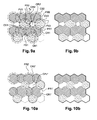
- FIGS 9 (a) and 9 (b) A first embodiment of the method according to the invention is illustrated in Figures 9 (a) and 9 (b) .
- an antenna beam associated with a cell is not capable of producing a hexagonal shape, a good approximation of considering a circular beam.
- a cell is determined as the portion of the service area associated with the beam providing the highest gain on that area among all the beams of the satellite.
- the beams do not stop at the edges of the cell: the method according to the invention advantageously uses the overflow of each beam on the cells contiguous to the cell with which it is associated.
- all the yellow beams are defective so that the cells associated with the yellow beams are not covered: these cells are called defective cells.
- the cells contiguous to the defective cells are enlarged.
- the beams of the same "color" being non-adjacent, the contiguous cells therefore correspond to different colors.
- By enlargement of a contiguous cell is meant associating the beam associated with this contiguous cell with a part of the surface of the defective cell.
- the six beams (two red FR1 and FR2, two blue FB1 and FB2 and two green FV1 and FV2) associated respectively with the 6 cells CR1, CR2, CB1, CB2, CV1 and CV2 contiguous to the defective cell are each associated with a portion of the surface of the hexagonal cell so the uncovered surface CPJ 'is well below the surface of the defective CPJ cell as shown in FIG.
- the beams FR1, FR2, FB1, FB2, FV1 and FV2 also continue to be associated respectively with the CR1, CR2, CB1, CB2, CV1 and CV2 cells.
- the size of the beams FR1, FR2, FB1, FB2, FV1 and FV2 does not increase, the magnification of the beams represented in FIG. figure 9 a) (ie the two concentric circles, one dashed and the other solid line, respectively showing the beam used in operating mode according to the prior art and the beam in operating mode according to the method according to the invention) only to illustrate the fact that these are associated to a larger surface: the size of the beams remains the same.
- the frequency bands allocated to the beams remain the same: there is no reorganization of the frequency bands but in the defective cell the frequency bands and the polarizations are defined according to the sectors (geographical) and the extension. beams (ie the terminals located in the defective cell transmit and receive in the frequency band associated with the new enlarged cell in which they are located but this does not imply any change of infrastructure).
- the method according to the invention provides a solution in intermediate degraded mode between the optimal solution with all the cells in operation and the solution with loss of beams without partial recovery of service area.
- Another way of describing the invention is to consider that some of the terrestrial terminals initially in the defective cell are reassigned to the cells contiguous to the defective cell.
- the terrestrial terminal T1 which originally belonged to the faulty cell belongs to the cell CV1: the cell CV1 is "enlarged” (ie the radiofrequency link is on the beam FV1) to cover the area to which originally belonged to the T1 terminal.
- the terrestrial terminal T2 which initially belonged to the defective cell belongs to the cell CV2: the cell CV2 is "enlarged” (ie the radiofrequency link is made on the beam FV2) to make it possible to cover the zone to which originally belonged the terminal T2.
- the figure 9 b) represents the service area covered by the method according to this first embodiment of the invention using the extension of all the cells contiguous to the defective cell.
- the figure 10 b) represents the service area covered by the method according to this second embodiment of the invention using the extension of the cells contiguous to the defective cell and having a polarization in the same direction as the defective cell.
- the method according to the invention applies equally to an uplink from cells comprising terrestrial terminals to the satellite (return channel) and to a downlink from the satellite to the cells comprising terrestrial terminals (forward channel).
- the four-color scheme is symmetrical between the forward and return channels.
- a cell is the same color in reception and transmission.
- this color does not correspond to the same frequency in the forward channel (reception of the signal transmitted by the satellite between 19.7 and 20.2 GHz) and in return channel (emission towards the satellite between 29.5 and 30.0 GHz).
- the polarization is reversed between the transmitted signal and the received signal, which allows the use of simpler and less expensive terminals, the separation between transmitted signal and received signal being polarized and not requiring specific filtering.
- the parts of the defective cell reallocated to another adjacent beam as well as on the Figures 9 (a) and 9 (b) than on the Figures 10 (a) and 10 (b) , have the same surface.
- the figure 11 illustrates this embodiment. It can be seen that the portion P1 associated with the red beam FR1 "has a surface smaller than the area of the portion P2 associated with the red beam FR2". Such an implementation of the method according to the invention can prove particularly useful when it is desired to recover an operation on a part including a location of interest L.
- the enlargement of the cells implies that the earth stations must manage an extension of the number of terrestrial terminals with which they must communicate. This is possible in the case of a centralized management of MAC ("Media Access Control") or IP ("Internet Protocol”) addresses of the terminals. This centralized management allows all earth stations, almost in real time, to know which terminals are attached to them, and to regain control in the event of a failure.
- Another solution may be to give the terrestrial terminals an address in normal operating mode connecting them to their reference earth station and an "emergency" address (in case of failure of the beam to which they are attached) connecting them to a back-up earth station, the reconfiguration thus becoming very fast.
- the method according to the invention finds a particularly advantageous application in the case of the failure of a terrestrial station involving the loss of all the beams generated from the station (in the example cited above with reference to the state of the technique, 16 bundles were lost).
- the satellite data transmission network is constructed so that for a first beam assigned to a first earth station, all the beams adjacent to said first beam are each assigned to a different ground station of the first station. earthly. In other words, if a beam is "served" by a ground station, the beams surrounding that beam are necessarily served by another earth station.
- Such a configuration makes it possible, in the event of failure of a terrestrial station, to always have the beams adjacent to the lost beam coming from the defective ground station; implementation of the method according to the invention is then always possible since there are always bundles associated with the cells contiguous to the lost cell. It will be noted that such an architecture is particularly original insofar as the beams served by the same earth station are not grouped geographically but instead are voluntarily remote so as to implement the method according to the invention.
- the invention has been more particularly described in the case of a four-color scheme but it can be applied to another number of colors (two for example).
Abstract
Description
La présente invention concerne un procédé d'établissement de liaisons radiofréquences via un satellite de télécommunication à plusieurs faisceaux, dit satellite multifaisceaux ou multispots, entre au moins une station terrestre et une zone de services composée d'une pluralité de zones de couverture élémentaires, dites cellules, chaque cellule comportant une pluralité de terminaux terrestres. Ce type de satellite permet l'utilisation de plusieurs faisceaux d'antennes à bord du satellite pour couvrir des zones géographiques contiguës ou cellules, au lieu d'un seul faisceau large.The present invention relates to a method for establishing radio frequency links via a multi-beam or multispots telecommunication satellite, between at least one terrestrial station and a service area composed of a plurality of elementary coverage areas, called cells, each cell having a plurality of terrestrial terminals. This type of satellite allows the use of several antenna beams on board the satellite to cover contiguous geographical areas or cells, instead of a single wide beam.
De tels satellites multifaisceaux permettent d'établir plusieurs liaisons radiofréquences occupant une même bande de fréquence sur des faisceaux différents.Such multibeam satellites make it possible to establish several radio frequency links occupying the same frequency band on different beams.
Dans le cas de système de télécommunication satellitaire large bande (« broadband » en anglais) à haut débit, le satellite est utilisé de façon bidirectionnelle, c'est-à-dire à la fois pour :
- relayer des données émises par une station terrestre vers une pluralité de terminaux terrestres : cette première liaison de type point à multipoints constitue la voie aller (« forward link » en anglais) ;
- relayer vers la station terrestre les données émises par les terminaux terrestres : cette deuxième liaison, de type multipoints à point, constitue la voie retour (« return link » en anglais).
- relaying data transmitted by a terrestrial station to a plurality of terrestrial terminals: this first point-to-multipoint link is the forward link;
- relaying data sent by terrestrial terminals to the land station: this second link, of the multipoint-to-point type, constitutes the return link.
On notera qu'un service de radiodiffusion par satellite peut être considéré comme équivalent à la voie aller d'un système bidirectionnel tel que décrit ci-dessus.Note that a broadcasting-satellite service may be considered equivalent to the forward path of a bidirectional system as described above.
Un exemple de voie aller dans une configuration multifaisceaux est illustré en
Des signaux sont envoyés vers un satellite multifaisceaux 3 sur une liaison montante LM par une station terrestre 2 telle qu'une passerelle de communication (« gateway » en anglais) reliée à une dorsale Internet 5. Ces signaux sont ensuite traités au niveau du satellite 3 puis retransmis sur une liaison descendante LD sous la forme d'une pluralité de faisceaux ou spots formant des zones de couvertures élémentaires ou cellules C1 à C8 dans lesquels sont situés des terminaux terrestres 6. Chaque cellule C1 à C8 est associée à un faisceau SP1 à SP8. On notera que, dans le cas de la configuration 1, les huit cellules C1 à C8 associés respectivement aux huit faisceaux SP1 à SP8 forment un groupe de cellules servies par la même station terrestre 2. La voie retour des terminaux terrestres 6 vers la station terrestre 2 fonctionne de manière identique avec une direction de communication inverse.Signals are sent to a multibeam satellite 3 on an uplink LM by a
La coordination des fréquences entre opérateurs se fait dans le cadre d'une règlementation édictée par l'Union Internationale des Télécommunications (IUT) : ainsi, à titre d'exemple, la bande Ka pour la région 1 (Europe, Afrique, Moyen-Orient) est définie dans le tableau 1 ci-dessous :
D'autres bandes telles que la bande Ku peuvent également être utilisées.Other bands such as the Ku band can also be used.
Étant donné que le gain d'une antenne est inversement proportionnel à l'ouverture du faisceau, il est nécessaire d'utiliser des antennes multifaisceaux pour couvrir une zone étendue avec un gain homogène et élevé. Plus le nombre de faisceaux sera grand, plus petite sera l'ouverture de chaque faisceau. Ainsi, le gain sur chaque faisceau et donc le gain sur la zone de service à couvrir sera augmenté. Comme nous l'avons mentionné plus haut, une zone de service à couvrir est formée par une pluralité de cellules contiguës (zones de couvertures élémentaires), un faisceau étant associé à chaque cellule. Une zone de couverture multifaisceaux homogène SA est représentée en
La configuration 1 telle que représentée en
On connaît des schémas de réutilisation de fréquences, dits schémas de couleur, faisant correspondre une couleur à chacun des faisceaux du satellite. Ces schémas de couleur sont utilisés pour décrire l'attribution d'une pluralité de bandes de fréquences aux faisceaux du satellite en vue de transmissions radiofréquences à réaliser dans chacun de ces faisceaux. Dans ces schémas, chaque couleur correspond à une de ces bandes de fréquences.Frequency reuse schemes, called color schemes, are known that map a color to each of the satellite beams. These color schemes are used to describe the assignment of a plurality of frequency bands to the satellite beams for radio frequency transmissions to be performed in each of these beams. In these diagrams, each color corresponds to one of these frequency bands.
Ces satellites multifaisceaux permettent par ailleurs d'émettre (et de recevoir) des transmissions polarisées : la polarisation peut être linéaire (dans ce cas les deux sens de polarisation sont respectivement horizontal et vertical) ou circulaire (dans ce cas les deux sens de polarisation sont respectivement circulaire gauche ou circulaire droit). On notera que dans l'exemple de la
Selon un schéma à quatre couleurs (rouge, jaune, bleu, vert) avec un spectre de fréquence de 500 MHz pour chaque polarisation, les transmissions étant polarisées dans l'un des deux sens de polarisation circulaire droit ou circulaire gauche, chaque couleur est associée à une bande de 250 MHz et un sens de polarisation.According to a four-color scheme (red, yellow, blue, green) with a frequency spectrum of 500 MHz for each polarization, the transmissions being polarized in one of the two directions of left circular or right circular polarization, each color is associated at a band of 250 MHz and a direction of polarization.
Nous prendrons dans toute la suite de la description la convention suivante :
- la couleur rouge est représentée par des traits hachurés vers la droite ;
- la couleur jaune est représentée par des points denses ;
- la couleur bleue est représentée par des traits hachurés vers la gauche ;
- la couleur verte est représentée par des points dispersés.
- the red color is represented by hatched lines to the right;
- the yellow color is represented by dense dots;
- the blue color is represented by hatched lines to the left;
- the green color is represented by scattered points.
Une couleur est ainsi associée à chaque faisceau du satellite (et donc une cellule) de sorte que les faisceaux d'une même « couleur » soient non adjacents : les cellules contiguës correspondent donc à des couleurs différentes.A color is thus associated with each beam of the satellite (and therefore a cell) so that the beams of the same "color" are non-adjacent: the contiguous cells therefore correspond to different colors.
Les
Un exemple de schéma à quatre couleurs pour la couverture de l'Europe est représenté en
Ce type de schéma est applicable aussi bien en liaison montante qu'en liaison descendante. Au niveau du satellite, la création d'un faisceau se fait à partir d'un cornet rayonnant vers un réflecteur. Un réflecteur peut être associé à une couleur de sorte qu'une couverture à quatre couleurs est assurée par quatre réflecteurs.This type of scheme is applicable for both uplink and downlink. At the level of the satellite, the creation of a beam is made from a horn radiating towards a reflector. A reflector may be associated with a color so that four-color coverage is provided by four reflectors.
La
Le plan PMVA correspondant à la liaison montante sur la voie aller (de la station terrestre au satellite) dispose de 2 GHz de spectre disponible en fréquence de sorte que 16 canaux de 250 MHz de bande passante sont générés par une station terrestre (8 canaux pour chaque polarisation). Ces 16 canaux, après traitement par la charge utile du satellite formeront 16 faisceaux. Dans cette exemple, 16 faisceaux (et donc 16 cellules) sont générés par une station terrestre.The PMVA plane corresponding to the uplink on the forward path (from the terrestrial station to the satellite) has 2 GHz spectrum available in frequency so that 16 channels of 250 MHz bandwidth are generated by a terrestrial station (8 channels for each polarization). These 16 channels, after processing by the payload of the satellite will form 16 beams. In this example, 16 beams (and therefore 16 cells) are generated by a ground station.
On notera que le schéma à quatre couleurs, pour la voie aller, associe à chaque faisceau d'un motif de quatre faisceaux adjacents une des quatre couleurs suivantes :
- une première couleur rouge correspondant à une première bande de 250 MHz (partie inférieure du spectre disponible de 500 MHz) et au sens de polarisation circulaire droit ;
- une deuxième couleur bleue correspondant à la même première bande de 250 MHz et au sens de polarisation circulaire gauche ;
- une troisième couleur jaune correspondant à une deuxième bande de 250 MHz (partie supérieure du spectre disponible de 500 MHz) et au sens de polarisation circulaire droit ;
- une quatrième couleur verte correspondant à la même deuxième bande de 250 MHz et au sens de polarisation circulaire gauche.
- a first red color corresponding to a first 250 MHz band (lower part of the available 500 MHz spectrum) and in the right circular polarization direction;
- a second blue color corresponding to the same first band of 250 MHz and in the direction of left circular polarization;
- a third yellow color corresponding to a second 250 MHz band (upper half of the available 500 MHz spectrum) and in the right circular polarization direction;
- a fourth green color corresponding to the same second band of 250 MHz and in the direction of left circular polarization.
Sur la voie retour, les polarisations sont inversées de sorte que les couleurs rouge et jaune ont une polarisation circulaire gauche et les couleurs bleue et verte ont une polarisation circulaire droite.On the return path, the polarizations are reversed so that the red and yellow colors have left circular polarization and the blue and green colors have a right circular polarization.
Une telle configuration est cependant susceptible de poser quelques difficultés.Such a configuration is however likely to pose some difficulties.
En effet, la moindre défaillance entraînant la perte de faisceaux a un impact direct sur les cellules associées à ces faisceaux dont la couverture n'est plus assurée. Une telle défaillance peut être par exemple due à :
- la défaillance d'une station terrestre impliquant la perte des l'ensemble des faisceaux générés à partir de la station (dans notre exemple précédent 16 faisceaux) ;
- la panne d'une antenne à bord du satellite (on perd alors généralement 25% des faisceaux provenant du satellite avec quatre antennes sur le satellite et donc 25% de la surface couverte par le satellite) ;
- le mauvais fonctionnement d'un multiplexeur ou d'un filtre qui va entraîner la perte des faisceaux directement en correspondance;
- la défaillance d'un amplificateur de puissance HPA (« High Power Amplifier » en anglais) généralement formé par un amplificateur de canal CAMP (« Chanel AMPlifier » en anglais) et un amplificateur à tube à ondes progressives TWTA (« Traveling Wave Tube Amplifier » en anglais) ou l'échec partiel du système de puissance sur le satellite : la perte peut aller de un à plusieurs faisceaux ; ainsi, il y aura un faisceau perdu si ce faisceau est généré par un amplificateur unique et que cet amplificateur (ainsi que son amplificateur redondant) est perdu ; il y aura deux faisceaux (ou plus généralement N faisceaux) perdus si l'amplificateur (et sa redondance) est utilisé par deux (plus généralement N) faisceaux (i.e. deux faisceaux par tube ou plus généralement N faisceaux par tube) ; on peut même perdre quatre faisceaux s'il s'agit de la perte du système d'alimentation mis en commun par deux amplificateurs (« Electronic Power Conditioner double » en anglais), eux-mêmes utilisés pour générer deux faisceaux chacun.
- the failure of a ground station involving the loss of all the beams generated from the station (in our previous example 16 beams);
- the failure of an antenna on board the satellite (typically 25% of the beams from the satellite are lost with four antennas on the satellite and thus 25% of the area covered by the satellite);
- the malfunction of a multiplexer or a filter which will cause the loss of the beams directly in correspondence;
- the failure of a power amplifier HPA ("High Power Amplifier" in English) generally formed by a channel amplifier CAMP ("Chanel AMPlifier" in English) and a traveling wave tube amplifier TWTA (Traveling Wave Tube Amplifier) in English) or the partial failure of the power system on the satellite: the loss can go from one to several beams; thus, there will be a lost beam if this beam is generated by a single amplifier and this amplifier (as well as its redundant amplifier) is lost; there will be two beams (or more generally N beams) lost if the amplifier (and its redundancy) is used by two (more generally N) beams (ie two beams per tube or more generally N bundles per tube); it can even lose four beams if it is the loss of the power system pooled by two amplifiers ("Electronic Power Conditioner double"), themselves used to generate two beams each.
La
Dans ce contexte, la présente invention vise à fournir un procédé d'établissement de liaisons radiofréquences via un satellite multifaisceaux entre au moins une station terrestre et une zone de services composée d'une pluralité de cellules, ledit procédé permettant d'améliorer la couverture en cas de perte d'un ou d'une pluralité de faisceaux.In this context, the present invention aims at providing a method for establishing radio frequency links via a multibeam satellite between at least one terrestrial station and a service area composed of a plurality of cells, said method making it possible to improve the coverage by case of loss of one or a plurality of beams.
A cette fin, l'invention propose un procédé d'établissement de liaisons radiofréquences via un satellite de télécommunication à plusieurs faisceaux, dit satellite multifaisceaux, entre au moins une station terrestre et une zone de services composée d'une pluralité de zones de couverture élémentaires, dites cellules, chaque cellule comportant une pluralité de terminaux terrestres et étant associée à un faisceau auquel est attribuée une bande de fréquence, ledit procédé étant caractérisé en ce qu'en cas de perte d'un faisceau associé à une cellule, dite cellule défaillante, le faisceau associé à au moins une cellule contiguë à ladite cellule défaillante est également associé à une partie de ladite cellule défaillante.To this end, the invention proposes a method for establishing radio frequency links via a multi-beam satellite, said multibeam satellite, between at least one terrestrial station and a service area composed of a plurality of elementary coverage areas. , said cells, each cell comprising a plurality of terrestrial terminals and being associated with a beam to which a frequency band is allocated, said method being characterized in that , in the event of loss of a beam associated with a cell, said defective cell , the beam associated with at least one cell contiguous to said faulty cell is also associated with a part of said faulty cell.
Grâce à l'invention, on « agrandit » au moins une cellule contiguë à la cellule défaillante ; en d'autres termes, on utilise le faisceau associé à cette cellule contiguë pour couvrir une partie de la surface de la cellule défaillante en utilisant la performance du faisceau à l'extérieur de sa propre cellule.. Dans le cas où la cellule de référence dans laquelle se trouve un terminal terrestre ne peut plus fonctionner, il est en effet possible de rattacher ce terminal à un autre faisceau en « étendant » la cellule associée à ce faisceau. Ainsi, une partie des terminaux terrestres appartenant initialement à la cellule défaillante se retrouve dans une cellule contiguë « agrandie » dont le faisceau associé couvre non seulement la cellule contiguë mais également une partie de la cellule défaillante. Bien sûr, le gain de ce nouveau faisceau est inférieur à celui du faisceau de référence perdu, le G/T et la PIRE du satellite offerts par le nouveau faisceau étant inférieurs, mais le procédé selon l'invention offre une solution de secours en mode dégradé limitant la perte de couverture de la zone de service due au faisceau perdu. On notera que le faisceau couvre non seulement la cellule à laquelle il est initialement associé mais également la partie de la cellule défaillante sans modification de la taille dudit faisceau : c'est bien la taille de la cellule contiguë qui est agrandie via l'association partielle de son faisceau à la cellule défaillante. Ceci est rendu possible par le fait que les faisceaux, assimilés à des spots circulaires, ne s'arrêtent pas au bord de la cellule généralement hexagonale à laquelle ils sont associés. On notera également que le procédé selon l'invention s'applique tout autant sur une liaison montante à partir des cellules comportant des terminaux terrestres vers le satellite (voie retour) que sur une liaison descendante du satellite vers les cellules comportant des terminaux terrestres (voie aller). Il convient également de mentionner que le procédé selon l'invention s'applique sans modification à bord du satellite : les faisceaux restent les mêmes et on utilise avantageusement le débordement de faisceaux sur des cellules contiguës aux cellules auxquelles ils sont associés.Thanks to the invention, one "enlarges" at least one cell contiguous to the defective cell; in other words, the beam associated with this contiguous cell is used to cover part of the surface of the faulty cell by using the beam performance outside its own cell. In the case where the reference cell in which there is a terrestrial terminal can no longer function, it is indeed possible to connect this terminal to another beam by "extending" the cell associated with this beam. Thus, a part of the terrestrial terminals initially belonging to the defective cell is found in an "enlarged" contiguous cell whose associated beam covers not only the contiguous cell but also a part of the defective cell. Of course, the gain of this new beam is lower than that of the lost reference beam, the G / T and the EIRP of the satellite offered by the new beam being lower, but the method according to the invention provides a backup solution in degraded mode limiting the loss of coverage of the service area due to the lost beam. It will be noted that the beam covers not only the cell to which it is initially associated but also the part of the faulty cell without modifying the size of said beam: it is indeed the size of the contiguous cell which is enlarged via the partial association from his beam to the faulty cell. This is made possible by the fact that the beams, assimilated to circular spots, do not stop at the edge of the generally hexagonal cell with which they are associated. It will also be noted that the method according to the invention applies equally to an uplink from the cells comprising terrestrial terminals to the satellite (return channel) and to a downlink from the satellite to the cells comprising terrestrial terminals (channel to go). It should also be mentioned that the method according to the invention applies without modification on board the satellite: the beams remain the same and advantageously the overflow of beams on cells contiguous to the cells with which they are associated.
Le dispositif selon l'invention peut également présenter une ou plusieurs des caractéristiques ci-dessous, considérées individuellement ou selon toutes les combinaisons techniquement possibles :
- Avantageusement, une pluralité de faisceaux associés chacun à une cellule contiguë à ladite cellule défaillante sont chacun associé à une partie de ladite cellule défaillante.
- Advantageously, a plurality of beams each associated with a cell contiguous to said faulty cell are each associated with a part of said faulty cell.
Selon une première variante, chacune desdites parties contribue à une surface égale de couverture.According to a first variant, each of said parts contributes to an equal area of coverage.
Selon une seconde variante, au moins deux desdites parties contribuent à une surface différente de couverture.According to a second variant, at least two of said parts contribute to a different surface area of coverage.
Avantageusement, chaque faisceau présente une bande de fréquence montante ou descendante donnée et un sens de polarisation donné, les faisceaux présentant une même bande de fréquence et un même sens de polarisation étant non adjacents.Advantageously, each beam has a given rising or falling frequency band and a given direction of polarization, the beams having the same frequency band and the same direction of polarization being non-adjacent.
Préférentiellement, lesdites bandes de fréquence montantes ou descendantes appartiennent à l'une des bandes suivantes : Ka, Ku.Preferably, said rising or falling frequency bands belong to one of the following bands: Ka, Ku.
Selon un premier mode de réalisation, les terminaux terrestres de ladite cellule défaillante sont aptes à émettre et/ou recevoir des signaux dans les deux sens de polarisation de sorte que l'ensemble des faisceaux associés aux cellules contiguës à ladite cellule défaillante peuvent être associés à une partie de ladite cellule défaillante. Le sens de la polarisation d'émission et de réception est, en général, opposé.According to a first embodiment, the terrestrial terminals of said faulty cell are able to transmit and / or receive signals in both directions of polarization so that all the beams associated with the cells contiguous to said faulty cell can be associated with a part of said faulty cell. The direction of the transmission and reception polarization is, in general, opposite.
Selon un second mode de réalisation, les terminaux terrestres de ladite cellule défaillante sont aptes à émettre et/ou recevoir des signaux dans un seul sens de polarisation de sorte que seuls les faisceaux associés aux cellules contiguës à ladite cellule défaillante et présentant le même sens de polarisation que le faisceau défaillant peuvent être associés à une partie de ladite cellule défaillante.According to a second embodiment, the terrestrial terminals of said faulty cell are able to transmit and / or receive signals in a single direction of polarization so that only the beams associated with the cells contiguous to said faulty cell and having the same sense of direction. polarization that the faulty beam can be associated with a portion of said faulty cell.
De manière particulièrement avantageuse, lesdites liaisons radiofréquences sont établies entre une pluralité de stations terrestres et ladite zone de service de sorte que, pour un premier faisceau affecté à une première station terrestre, l'ensemble des faisceaux adjacents au dit premier faisceau sont chacun affectés à une station terrestre différente de ladite première station terrestre.Particularly advantageously, said radiofrequency links are established between a plurality of earth stations and said service area so that, for a first beam assigned to a first earth station, all the beams adjacent to said first beam are each assigned to a land station different from said first land station.
Préférentiellement, ladite perte d'un faisceau intervient suite à l'une des défaillances suivantes :
- défaillance d'une station terrestre ;
- défaillance d'une antenne dudit satellite multifaisceaux;
- défaillance d'un composant du répéteur dudit satellite multifaisceaux.
- failure of a land station;
- failure of an antenna of said multibeam satellite;
- failure of a repeater component of said multibeam satellite.
D'autres caractéristiques et avantages de l'invention ressortiront clairement de la description qui en est donnée ci-dessous, à titre indicatif et nullement limitatif, en référence aux figures annexées, parmi lesquelles :
- la
figure 1 est une représentation schématique simplifiée d'une configuration multifaisceaux; - la
figure 2 a) représente un exemple de zone de couverture composée d'une pluralité d'hexagones disjoints ; - la
figure 2 b) représente une approximation de la zone de couverture de lafigure 2 a) composée d'une pluralité de faisceaux circulaires ; - les
figures 3 a) et 3 b) reprennent l'illustration desfigures 2 a) et 2 b) avec un schéma à quatre couleurs; - la
figure 4 illustre un schéma à quatre couleurs pour la couverture de l'Europe ; - la
figure 5 illustre un plan de fréquence en bande Ka ; - la
figure 6 reprend l'illustration de lafigure 3 b) en cas de perte des faisceaux jaunes ; - la
figure 7 reprend lafigure 4 en cas de défaillance d'une station terrestre ; - la
figure 8 est un agrandissement de lafigure 7 au niveau de la Grande Bretagne ; - les
figures 9 a) et b) illustrent la mise en oeuvre du procédé selon un premier mode de réalisation de l'invention; - les
figures 10 a) et b) illustrent la mise en oeuvre du procédé selon un second mode de réalisation de l'invention; - la
figure 11 illustre la mise en oeuvre du procédé selon un troisième mode de réalisation de l'invention ; - la
figure 12 illustre la mise en oeuvre du troisième mode de réalisation de l'invention dans la situation représentée enfigure 8 .
- the
figure 1 is a simplified schematic representation of a multibeam configuration; - the
figure 2 a) represents an example of a coverage area composed of a plurality of disjoint hexes; - the
Figure 2 (b) represents an approximation of the coverage area of thefigure 2 a) composed of a plurality of circular beams; - the
figures 3 a) and 3 b) reproduce the illustration offigures 2 a) and 2 b) with a four-color scheme; - the
figure 4 illustrates a four-color scheme for Europe's coverage; - the
figure 5 illustrates a Ka-band frequency plan; - the
figure 6 resumes the illustration of theFigure 3 (b) in case of loss of yellow beams; - the
figure 7 resumesfigure 4 in case of failure of a land station; - the
figure 8 is an enlargement of thefigure 7 at the level of Great Britain; - the
Figures 9 (a) and (b) illustrate the implementation of the method according to a first embodiment of the invention; - the
Figures 10 (a) and (b) illustrate the implementation of the method according to a second embodiment of the invention; - the
figure 11 illustrates the implementation of the method according to a third embodiment of the invention; - the
figure 12 illustrates the implementation of the third embodiment of the invention in the situation shown in FIG.figure 8 .
Dans toutes les figures, les éléments communs portent les mêmes numéros de référence.In all the figures, the common elements bear the same reference numbers.
La
Le procédé selon l'invention permet de réduire la perte de couverture engendrée par ces cellules perdues.The method according to the invention makes it possible to reduce the loss of coverage generated by these lost cells.
Un premier mode de réalisation du procédé selon l'invention est illustré en
On notera que le mode de réalisation décrit en référence aux
Le procédé selon l'invention s'applique tout autant sur une liaison montante à partir des cellules comportant des terminaux terrestres vers le satellite (voie retour) que sur une liaison descendante du satellite vers les cellules comportant des terminaux terrestres (voie aller). Le schéma à quatre couleurs est symétrique entre la voie aller et la voie retour. Une cellule est de la même couleur en réception et en transmission. Par contre, cette couleur ne correspond pas à la même fréquence en voie aller (réception du signal émis par le satellite entre 19.7 et 20.2 GHz) et en voie retour (émission en direction du satellite entre 29.5 et 30.0 GHz). De plus, la polarisation est inversée entre le signal émis et le signal reçu, ce qui permet l'utilisation de terminaux plus simples et moins coûteux, la séparation entre signal transmis et signal reçu se faisant par polarisation et ne nécessitant pas de filtrage spécifique. En reprenant le plan de fréquence de la
On notera que les parties de la cellule défaillante réallouées à un autre faisceau adjacent, aussi bien sur les
L'agrandissement des cellules implique que les stations terrestres doivent gérer une extension du nombre de terminaux terrestres avec lesquels elles doivent communiquer. Ceci est possible dans le cas d'une gestion centralisée des adresses de type MAC («Media Access Control » en anglais) ou IP (« Internet Protocol » en anglais) des terminaux. Cette gestion centralisée permet à toutes les stations terrestres, quasiment en temps réel, de savoir quels sont les terminaux qui leur sont rattachés, et de reprendre leur contrôle en cas de défaillance. Une autre solution peut consister à donner aux terminaux terrestres une adresse en mode de fonctionnement normal les reliant à leur station terrestre de référence et une adresse "de secours" (en cas de défaillance du faisceau auquel ils sont rattachés) les reliant à une station terrestre de secours, la reconfiguration devenant ainsi très rapide.The enlargement of the cells implies that the earth stations must manage an extension of the number of terrestrial terminals with which they must communicate. This is possible in the case of a centralized management of MAC ("Media Access Control") or IP ("Internet Protocol") addresses of the terminals. This centralized management allows all earth stations, almost in real time, to know which terminals are attached to them, and to regain control in the event of a failure. Another solution may be to give the terrestrial terminals an address in normal operating mode connecting them to their reference earth station and an "emergency" address (in case of failure of the beam to which they are attached) connecting them to a back-up earth station, the reconfiguration thus becoming very fast.
Le procédé selon l'invention trouve une application particulièrement intéressante dans le cas de la défaillance d'une station terrestre impliquant la perte de l'ensemble des faisceaux générés à partir de la station (dans l'exemple cité précédemment en référence à l'état de la technique, 16 faisceaux étaient perdus). Dans ce cas, le réseau de transmission de données par satellite est construit de sorte que pour un premier faisceau affecté à une première station terrestre, l'ensemble des faisceaux adjacents au dit premier faisceau sont chacun affectés à une station terrestre différente de cette première station terrestre. En d'autres termes, si un faisceau est « servi » par une station terrestre, les faisceaux entourant ce faisceau sont nécessairement servis par une autre station terrestre. Une telle configuration permet, en cas de défaillance d'une station terrestre, de toujours disposer des faisceaux adjacents au faisceau perdu issu de la station terrestre défaillante ; la mise en oeuvre du procédé selon l'invention est alors toujours possible puisqu'on dispose toujours des faisceaux associés aux cellules contiguës à la cellule perdue. On notera qu'une telle architecture est particulièrement originale dans la mesure où les faisceaux servis par une même station terrestre ne sont pas regroupés géographiquement mais sont au contraire volontairement éloignés de façon à pouvoir mettre en oeuvre le procédé selon l'invention.The method according to the invention finds a particularly advantageous application in the case of the failure of a terrestrial station involving the loss of all the beams generated from the station (in the example cited above with reference to the state of the technique, 16 bundles were lost). In this case, the satellite data transmission network is constructed so that for a first beam assigned to a first earth station, all the beams adjacent to said first beam are each assigned to a different ground station of the first station. earthly. In other words, if a beam is "served" by a ground station, the beams surrounding that beam are necessarily served by another earth station. Such a configuration makes it possible, in the event of failure of a terrestrial station, to always have the beams adjacent to the lost beam coming from the defective ground station; implementation of the method according to the invention is then always possible since there are always bundles associated with the cells contiguous to the lost cell. It will be noted that such an architecture is particularly original insofar as the beams served by the same earth station are not grouped geographically but instead are voluntarily remote so as to implement the method according to the invention.
Bien entendu, l'invention n'est pas limitée au mode de réalisation qui vient d'être décrit.Of course, the invention is not limited to the embodiment just described.
Notamment, l'invention a été plus particulièrement décrite dans le cas d'un schéma à quatre couleurs mais elle peut s'appliquer à un autre nombre de couleurs (deux par exemple).In particular, the invention has been more particularly described in the case of a four-color scheme but it can be applied to another number of colors (two for example).
En outre, nous avons décrit plus spécifiquement le cas de pertes de faisceaux liés à une couleur ou d'un ensemble de faisceaux servis par une même station terrestre mais le procédé selon l'invention s'applique tout autant dans le cas d'autres défaillances induisant la perte de faisceaux (mauvais fonctionnement d'un multiplexeur ou d'un filtre, défaillance d'un amplificateur de puissance HPA ou échec du système de puissance sur le satellite).In addition, we have more specifically described the case of loss of beams linked to a color or of a set of beams served by the same earth station, but the method according to the invention applies just as much in the case of other failures. inducing the loss of beams (bad operation of a multiplexer or filter, failure of an HPA power amplifier or failure of the power system on the satellite).
Claims (10)
Applications Claiming Priority (1)
| Application Number | Priority Date | Filing Date | Title |
|---|---|---|---|
| FR0851432A FR2928511B1 (en) | 2008-03-05 | 2008-03-05 | METHOD OF ESTABLISHING RADIO FREQUENCY LINKS VIA A MULTIFACEAL SATELLITE. |
Publications (3)
| Publication Number | Publication Date |
|---|---|
| EP2099142A2 true EP2099142A2 (en) | 2009-09-09 |
| EP2099142A3 EP2099142A3 (en) | 2009-09-30 |
| EP2099142B1 EP2099142B1 (en) | 2012-11-21 |
Family
ID=39870639
Family Applications (1)
| Application Number | Title | Priority Date | Filing Date |
|---|---|---|---|
| EP09305186A Not-in-force EP2099142B1 (en) | 2008-03-05 | 2009-03-02 | Method for establishing radio links by means of a multi-beam satellite |
Country Status (4)
| Country | Link |
|---|---|
| US (1) | US8594661B2 (en) |
| EP (1) | EP2099142B1 (en) |
| ES (1) | ES2399848T3 (en) |
| FR (1) | FR2928511B1 (en) |
Cited By (4)
| Publication number | Priority date | Publication date | Assignee | Title |
|---|---|---|---|---|
| WO2011089233A1 (en) * | 2010-01-25 | 2011-07-28 | Eutelsat S.A. | Method of interference reduction by geo - localisation of terminals in a satellite telecommunication network |
| EP2688142A1 (en) * | 2012-07-20 | 2014-01-22 | Thales | Multi-beam transmission and reception antenna with a plurality of sources per beam, antenna system and satellite telecommunication system comprising such an antenna |
| EP3082275A1 (en) * | 2015-04-15 | 2016-10-19 | Thales | Broadband multibeam satellite radio communication system with improved reuse of frequencies on the forward channel, and associated method for reuse |
| EP4304106A1 (en) * | 2022-07-07 | 2024-01-10 | Thales | Passive multibeam satellite radio communication system without redundancy |
Families Citing this family (5)
| Publication number | Priority date | Publication date | Assignee | Title |
|---|---|---|---|---|
| US8705407B2 (en) * | 2010-08-25 | 2014-04-22 | University Of Florida Research Foundation, Inc. | Efficient protocols against sophisticated reactive jamming attacks |
| EP3157178A1 (en) * | 2015-10-12 | 2017-04-19 | Eutelsat S.A. | Method for establishing radiofrequency links in a telecommunication network with an optimised ground gateway network |
| US11849469B2 (en) | 2021-06-18 | 2023-12-19 | Qualcomm Incorporated | Orbital angular momentum capability in millimeter wave and higher frequency bands |
| US11616555B2 (en) * | 2021-06-18 | 2023-03-28 | Qualcomm Incorporated | Spatial misalignment tracking for orbital angular momentum beams in millimeter wave and higher frequency bands |
| US11757516B2 (en) | 2021-06-18 | 2023-09-12 | Qualcomm Incorporated | Beam management procedure for OAM in MMW and higher bands |
Citations (1)
| Publication number | Priority date | Publication date | Assignee | Title |
|---|---|---|---|---|
| EP0812072A2 (en) | 1996-06-06 | 1997-12-10 | HE HOLDINGS, INC. dba HUGHES ELECTRONICS | Satellite communications apparatus using active redundancy |
Family Cites Families (15)
| Publication number | Priority date | Publication date | Assignee | Title |
|---|---|---|---|---|
| US5083131A (en) * | 1990-05-31 | 1992-01-21 | Hughes Aircraft Company | Local compensation of failed elements of an active antenna array |
| GB2280570B (en) * | 1993-07-31 | 1998-04-01 | Motorola Ltd | A communications system |
| GB2303764A (en) * | 1995-07-28 | 1997-02-26 | Int Mobile Satellite Org | Communication with a mobile station in an unknown spot beam |
| FR2762937B1 (en) * | 1997-05-05 | 1999-06-11 | Alsthom Cge Alcatel | ACTIVE ANTENNA WITH RADIANT ELEMENTS NETWORK WITH REDUNDANT ARCHITECTURE |
| US7020462B1 (en) * | 1997-06-02 | 2006-03-28 | The Directv Group, Inc. | Communications system using a satellite-based network with a plurality of spot beams providing ubiquitous coverage from two different satellites |
| US7184761B1 (en) * | 2000-03-27 | 2007-02-27 | The Directv Group, Inc. | Satellite communications system |
| EP1168672A3 (en) * | 2000-06-21 | 2004-01-02 | Northrop Grumman Corporation | Multiple satellite beam laydown with switchable bands for hopped satellite downlink |
| EA005472B1 (en) * | 2001-02-12 | 2005-02-24 | Ай Си О СЕРВИСИЗ ЛИМИТЕД | Communication apparatus and method |
| US6973287B2 (en) * | 2002-01-11 | 2005-12-06 | Northrop Grumman Corporation | Apparatus and method to implement a flexible hub-spoke satellite communications network |
| US7471645B2 (en) * | 2002-10-25 | 2008-12-30 | Hughes Network Systems, Llc | Method and system for multicast in a broadband satellite system |
| KR100619906B1 (en) * | 2004-09-24 | 2006-09-12 | 엘지전자 주식회사 | Mobile communication terminal for worship |
| FR2895852B1 (en) * | 2006-01-03 | 2008-02-22 | Alcatel Sa | IMPLIED RESOURCE RESERVATION IN A MULTI POINT OR MULTIPOINT TO MULTIPOINT TYPE POINT COMMUNICATION NETWORK |
| US7869759B2 (en) * | 2006-12-14 | 2011-01-11 | Viasat, Inc. | Satellite communication system and method with asymmetric feeder and service frequency bands |
| FR2929059B1 (en) * | 2008-03-21 | 2011-08-26 | Eutelsat | TELECOMMUNICATION NETWORK |
| US20130035033A1 (en) * | 2010-03-15 | 2013-02-07 | Henning Sanneck | Relay Nodes |
-
2008
- 2008-03-05 FR FR0851432A patent/FR2928511B1/en active Active
- 2008-04-16 US US12/082,985 patent/US8594661B2/en not_active Expired - Fee Related
-
2009
- 2009-03-02 EP EP09305186A patent/EP2099142B1/en not_active Not-in-force
- 2009-03-02 ES ES09305186T patent/ES2399848T3/en active Active
Patent Citations (1)
| Publication number | Priority date | Publication date | Assignee | Title |
|---|---|---|---|---|
| EP0812072A2 (en) | 1996-06-06 | 1997-12-10 | HE HOLDINGS, INC. dba HUGHES ELECTRONICS | Satellite communications apparatus using active redundancy |
Cited By (11)
| Publication number | Priority date | Publication date | Assignee | Title |
|---|---|---|---|---|
| WO2011089233A1 (en) * | 2010-01-25 | 2011-07-28 | Eutelsat S.A. | Method of interference reduction by geo - localisation of terminals in a satellite telecommunication network |
| FR2955725A1 (en) * | 2010-01-25 | 2011-07-29 | Eutelsat Sa | METHOD OF INTERFERENCE REMOVAL ASSISTED BY GEO-LOCATION OF TERMINALS IN A SATELLITE TELECOMMUNICATION NETWORK |
| RU2546334C2 (en) * | 2010-01-25 | 2015-04-10 | Этелсат С А | Method of eliminating interference in satellite telecommunication network by geolocalisation of terminals |
| US9031501B2 (en) | 2010-01-25 | 2015-05-12 | Eutelsat S A | Method of interference reduction by geo-localisation of terminals in a satellite telecommunication network |
| EP2688142A1 (en) * | 2012-07-20 | 2014-01-22 | Thales | Multi-beam transmission and reception antenna with a plurality of sources per beam, antenna system and satellite telecommunication system comprising such an antenna |
| FR2993716A1 (en) * | 2012-07-20 | 2014-01-24 | Thales Sa | MULTIFUNCTIONAL MULTI-SOURCE SENDING AND RECEIVING ANTENNA BY BEAM, ANTENNA SYSTEM AND SATELLITE TELECOMMUNICATION SYSTEM COMPRISING SUCH ANTENNA |
| US9306295B2 (en) | 2012-07-20 | 2016-04-05 | Thales | Multibeam transmitting and receiving antenna with multiple feeds per beam, system of antennas and satellite telecommunication system containing such an antenna |
| EP3082275A1 (en) * | 2015-04-15 | 2016-10-19 | Thales | Broadband multibeam satellite radio communication system with improved reuse of frequencies on the forward channel, and associated method for reuse |
| US9686009B2 (en) | 2015-04-15 | 2017-06-20 | Thales | Broadband multibeam satellite radio communication system with improved reuse of frequencies on the forward channel, and associated method for reuse |
| EP4304106A1 (en) * | 2022-07-07 | 2024-01-10 | Thales | Passive multibeam satellite radio communication system without redundancy |
| FR3137808A1 (en) * | 2022-07-07 | 2024-01-12 | Thales | Passive multi-beam satellite radio communications system without redundancy |
Also Published As
| Publication number | Publication date |
|---|---|
| US20090227252A1 (en) | 2009-09-10 |
| EP2099142A3 (en) | 2009-09-30 |
| FR2928511A1 (en) | 2009-09-11 |
| EP2099142B1 (en) | 2012-11-21 |
| ES2399848T3 (en) | 2013-04-03 |
| US8594661B2 (en) | 2013-11-26 |
| FR2928511B1 (en) | 2010-12-17 |
Similar Documents
| Publication | Publication Date | Title |
|---|---|---|
| EP2099142B1 (en) | Method for establishing radio links by means of a multi-beam satellite | |
| EP2723002B1 (en) | Satellite telecommunication system capable of providing traffic with star and mesh topology | |
| FR2783379A1 (en) | Multiple-beam satellite communications system, e.g. for digital TV, uses same beam for each uplink and downlink with antennas producing beams differing in size or shape for selective service areas on earth's surface | |
| FR2756997A1 (en) | SYSTEM AND METHOD FOR TRANSMITTING DATA PACKETS | |
| EP2104243B1 (en) | Telecommunications network | |
| EP2930862B1 (en) | Satellite communication system and method with multispot beam coverage having means for variable capacity allocation between the spot beams. | |
| EP3503431A1 (en) | Method for multi-beam coverage by grouping basic beams of the same colour, and telecommunications payload for implementing such a method | |
| CA2070082C (en) | Low orbit satellite telecommunication system for mobile stations | |
| EP2055633B1 (en) | Method of optimising the payload of a multi-beam telecommunications satellite | |
| FR2783376A1 (en) | Multiple-beam satellite communications system, e.g. for digital TV, uses same beam for each uplink and downlink with transmitter combining signals in single PA stage, individual downlink power control being available to ground stations | |
| FR2783378A1 (en) | Multiple beam satellite communications system, e.g. for digital TV, using transmitter combining signals of suitable low power and traffic rates for amplification by single or multiple TWT power amplifiers | |
| EP2481171A1 (en) | Payload for a multi-beam satellite | |
| EP2104242B1 (en) | Telecommunication network | |
| FR2751494A1 (en) | GEOSYNCHRONOUS TELECOMMUNICATIONS SATELLITE SYSTEM WHOSE SERVICE AREA CAN BE RECONFIGURED | |
| FR2930694A1 (en) | TELECOMMUNICATION NETWORK FOR THE ESTABLISHMENT OF RADIO FREQUENCY LINKS BETWEEN MAIN TERRESTRIAL STATIONS AND TERRESTRIAL TERMINALS VIA A MULTIFACEAL SATELLITE | |
| EP3975434B1 (en) | System and method for suppressing interfering uplink signals generated inside a spatial system for multi-spot communication | |
| EP3439199B1 (en) | Flexible payload architecture for vhts and hts applications | |
| EP1104124B1 (en) | Satellite telecommunication routing system | |
| EP3754866A1 (en) | Telecommunications payload with flexibility of coverage and capacity | |
| EP1938475A2 (en) | Device for transmitting and/or receiving frequency reuse signals by assigning a cell per terminal, for a communication satellite | |
| EP4207631A1 (en) | Method for configuring a moving satellite constellation and associated communication method, manager and communication system | |
| EP4304106A1 (en) | Passive multibeam satellite radio communication system without redundancy | |
| FR2783377A1 (en) | Multiple beam satellite communications system, e.g. for digital TV, using receiver with signal combining and separating architecture to feed channel amplifiers providing ground stations with individual downlink power control facility | |
| FR3029040A1 (en) | METHOD OF TRANSMITTING A PLURALITY OF DATA STREAMS FROM A PLURALITY OF TRANSMITTING STATIONS TO A PLURALITY OF RECEIVING STATIONS | |
| FR2950496A1 (en) | USEFUL LOAD FOR MULTIFACEAL SATELLITE |
Legal Events
| Date | Code | Title | Description |
|---|---|---|---|
| PUAI | Public reference made under article 153(3) epc to a published international application that has entered the european phase |
Free format text: ORIGINAL CODE: 0009012 |
|
| PUAL | Search report despatched |
Free format text: ORIGINAL CODE: 0009013 |
|
| AK | Designated contracting states |
Kind code of ref document: A2 Designated state(s): AT BE BG CH CY CZ DE DK EE ES FI FR GB GR HR HU IE IS IT LI LT LU LV MC MK MT NL NO PL PT RO SE SI SK TR |
|
| AX | Request for extension of the european patent |
Extension state: AL BA RS |
|
| AK | Designated contracting states |
Kind code of ref document: A3 Designated state(s): AT BE BG CH CY CZ DE DK EE ES FI FR GB GR HR HU IE IS IT LI LT LU LV MC MK MT NL NO PL PT RO SE SI SK TR |
|
| AX | Request for extension of the european patent |
Extension state: AL BA RS |
|
| 17P | Request for examination filed |
Effective date: 20091110 |
|
| AKX | Designation fees paid |
Designated state(s): AT BE BG CH CY CZ DE DK EE ES FI FR GB GR HR HU IE IS IT LI LT LU LV MC MK MT NL NO PL PT RO SE SI SK TR |
|
| RAP1 | Party data changed (applicant data changed or rights of an application transferred) |
Owner name: EUTELSAT SA |
|
| 17Q | First examination report despatched |
Effective date: 20110222 |
|
| GRAP | Despatch of communication of intention to grant a patent |
Free format text: ORIGINAL CODE: EPIDOSNIGR1 |
|
| GRAS | Grant fee paid |
Free format text: ORIGINAL CODE: EPIDOSNIGR3 |
|
| GRAA | (expected) grant |
Free format text: ORIGINAL CODE: 0009210 |
|
| AK | Designated contracting states |
Kind code of ref document: B1 Designated state(s): AT BE BG CH CY CZ DE DK EE ES FI FR GB GR HR HU IE IS IT LI LT LU LV MC MK MT NL NO PL PT RO SE SI SK TR |
|
| REG | Reference to a national code |
Ref country code: GB Ref legal event code: FG4D Free format text: NOT ENGLISH |
|
| REG | Reference to a national code |
Ref country code: CH Ref legal event code: EP |
|
| REG | Reference to a national code |
Ref country code: AT Ref legal event code: REF Ref document number: 585524 Country of ref document: AT Kind code of ref document: T Effective date: 20121215 |
|
| REG | Reference to a national code |
Ref country code: IE Ref legal event code: FG4D Free format text: LANGUAGE OF EP DOCUMENT: FRENCH |
|
| REG | Reference to a national code |
Ref country code: DE Ref legal event code: R096 Ref document number: 602009011336 Country of ref document: DE Effective date: 20130117 |
|
| REG | Reference to a national code |
Ref country code: DE Ref legal event code: R082 Ref document number: 602009011336 Country of ref document: DE Representative=s name: CABINET CAMUS LEBKIRI, FR |
|
| REG | Reference to a national code |
Ref country code: SE Ref legal event code: TRGR |
|
| REG | Reference to a national code |
Ref country code: ES Ref legal event code: FG2A Ref document number: 2399848 Country of ref document: ES Kind code of ref document: T3 Effective date: 20130403 |
|
| REG | Reference to a national code |
Ref country code: NO Ref legal event code: T2 Effective date: 20121121 |
|
| REG | Reference to a national code |
Ref country code: NL Ref legal event code: VDEP Effective date: 20121121 |
|
| REG | Reference to a national code |
Ref country code: AT Ref legal event code: MK05 Ref document number: 585524 Country of ref document: AT Kind code of ref document: T Effective date: 20121121 |
|
| REG | Reference to a national code |
Ref country code: LT Ref legal event code: MG4D |
|
| PG25 | Lapsed in a contracting state [announced via postgrant information from national office to epo] |
Ref country code: HR Free format text: LAPSE BECAUSE OF FAILURE TO SUBMIT A TRANSLATION OF THE DESCRIPTION OR TO PAY THE FEE WITHIN THE PRESCRIBED TIME-LIMIT Effective date: 20121226 Ref country code: FI Free format text: LAPSE BECAUSE OF FAILURE TO SUBMIT A TRANSLATION OF THE DESCRIPTION OR TO PAY THE FEE WITHIN THE PRESCRIBED TIME-LIMIT Effective date: 20121121 Ref country code: LT Free format text: LAPSE BECAUSE OF FAILURE TO SUBMIT A TRANSLATION OF THE DESCRIPTION OR TO PAY THE FEE WITHIN THE PRESCRIBED TIME-LIMIT Effective date: 20121121 |
|
| PG25 | Lapsed in a contracting state [announced via postgrant information from national office to epo] |
Ref country code: PT Free format text: LAPSE BECAUSE OF FAILURE TO SUBMIT A TRANSLATION OF THE DESCRIPTION OR TO PAY THE FEE WITHIN THE PRESCRIBED TIME-LIMIT Effective date: 20130321 Ref country code: SI Free format text: LAPSE BECAUSE OF FAILURE TO SUBMIT A TRANSLATION OF THE DESCRIPTION OR TO PAY THE FEE WITHIN THE PRESCRIBED TIME-LIMIT Effective date: 20121121 Ref country code: LV Free format text: LAPSE BECAUSE OF FAILURE TO SUBMIT A TRANSLATION OF THE DESCRIPTION OR TO PAY THE FEE WITHIN THE PRESCRIBED TIME-LIMIT Effective date: 20121121 Ref country code: PL Free format text: LAPSE BECAUSE OF FAILURE TO SUBMIT A TRANSLATION OF THE DESCRIPTION OR TO PAY THE FEE WITHIN THE PRESCRIBED TIME-LIMIT Effective date: 20121121 Ref country code: GR Free format text: LAPSE BECAUSE OF FAILURE TO SUBMIT A TRANSLATION OF THE DESCRIPTION OR TO PAY THE FEE WITHIN THE PRESCRIBED TIME-LIMIT Effective date: 20130222 |
|
| PG25 | Lapsed in a contracting state [announced via postgrant information from national office to epo] |
Ref country code: AT Free format text: LAPSE BECAUSE OF FAILURE TO SUBMIT A TRANSLATION OF THE DESCRIPTION OR TO PAY THE FEE WITHIN THE PRESCRIBED TIME-LIMIT Effective date: 20121121 |
|
| PG25 | Lapsed in a contracting state [announced via postgrant information from national office to epo] |
Ref country code: DK Free format text: LAPSE BECAUSE OF FAILURE TO SUBMIT A TRANSLATION OF THE DESCRIPTION OR TO PAY THE FEE WITHIN THE PRESCRIBED TIME-LIMIT Effective date: 20121121 Ref country code: SK Free format text: LAPSE BECAUSE OF FAILURE TO SUBMIT A TRANSLATION OF THE DESCRIPTION OR TO PAY THE FEE WITHIN THE PRESCRIBED TIME-LIMIT Effective date: 20121121 Ref country code: BG Free format text: LAPSE BECAUSE OF FAILURE TO SUBMIT A TRANSLATION OF THE DESCRIPTION OR TO PAY THE FEE WITHIN THE PRESCRIBED TIME-LIMIT Effective date: 20130221 Ref country code: EE Free format text: LAPSE BECAUSE OF FAILURE TO SUBMIT A TRANSLATION OF THE DESCRIPTION OR TO PAY THE FEE WITHIN THE PRESCRIBED TIME-LIMIT Effective date: 20121121 Ref country code: CZ Free format text: LAPSE BECAUSE OF FAILURE TO SUBMIT A TRANSLATION OF THE DESCRIPTION OR TO PAY THE FEE WITHIN THE PRESCRIBED TIME-LIMIT Effective date: 20121121 |
|
| PG25 | Lapsed in a contracting state [announced via postgrant information from national office to epo] |
Ref country code: RO Free format text: LAPSE BECAUSE OF FAILURE TO SUBMIT A TRANSLATION OF THE DESCRIPTION OR TO PAY THE FEE WITHIN THE PRESCRIBED TIME-LIMIT Effective date: 20121121 Ref country code: NL Free format text: LAPSE BECAUSE OF FAILURE TO SUBMIT A TRANSLATION OF THE DESCRIPTION OR TO PAY THE FEE WITHIN THE PRESCRIBED TIME-LIMIT Effective date: 20121121 |
|
| PLBE | No opposition filed within time limit |
Free format text: ORIGINAL CODE: 0009261 |
|
| STAA | Information on the status of an ep patent application or granted ep patent |
Free format text: STATUS: NO OPPOSITION FILED WITHIN TIME LIMIT |
|
| BERE | Be: lapsed |
Owner name: EUTELSAT SA Effective date: 20130331 |
|
| 26N | No opposition filed |
Effective date: 20130822 |
|
| PG25 | Lapsed in a contracting state [announced via postgrant information from national office to epo] |
Ref country code: MC Free format text: LAPSE BECAUSE OF NON-PAYMENT OF DUE FEES Effective date: 20130331 |
|
| REG | Reference to a national code |
Ref country code: CH Ref legal event code: PL |
|
| PG25 | Lapsed in a contracting state [announced via postgrant information from national office to epo] |
Ref country code: HR Free format text: LAPSE BECAUSE OF FAILURE TO SUBMIT A TRANSLATION OF THE DESCRIPTION OR TO PAY THE FEE WITHIN THE PRESCRIBED TIME-LIMIT Effective date: 20121121 |
|
| REG | Reference to a national code |
Ref country code: DE Ref legal event code: R097 Ref document number: 602009011336 Country of ref document: DE Effective date: 20130822 |
|
| REG | Reference to a national code |
Ref country code: IE Ref legal event code: MM4A |
|
| PG25 | Lapsed in a contracting state [announced via postgrant information from national office to epo] |
Ref country code: IE Free format text: LAPSE BECAUSE OF NON-PAYMENT OF DUE FEES Effective date: 20130302 Ref country code: CH Free format text: LAPSE BECAUSE OF NON-PAYMENT OF DUE FEES Effective date: 20130331 Ref country code: BE Free format text: LAPSE BECAUSE OF NON-PAYMENT OF DUE FEES Effective date: 20130331 Ref country code: LI Free format text: LAPSE BECAUSE OF NON-PAYMENT OF DUE FEES Effective date: 20130331 |
|
| PG25 | Lapsed in a contracting state [announced via postgrant information from national office to epo] |
Ref country code: MT Free format text: LAPSE BECAUSE OF FAILURE TO SUBMIT A TRANSLATION OF THE DESCRIPTION OR TO PAY THE FEE WITHIN THE PRESCRIBED TIME-LIMIT Effective date: 20121121 |
|
| PG25 | Lapsed in a contracting state [announced via postgrant information from national office to epo] |
Ref country code: CY Free format text: LAPSE BECAUSE OF FAILURE TO SUBMIT A TRANSLATION OF THE DESCRIPTION OR TO PAY THE FEE WITHIN THE PRESCRIBED TIME-LIMIT Effective date: 20121121 |
|
| PG25 | Lapsed in a contracting state [announced via postgrant information from national office to epo] |
Ref country code: HU Free format text: LAPSE BECAUSE OF FAILURE TO SUBMIT A TRANSLATION OF THE DESCRIPTION OR TO PAY THE FEE WITHIN THE PRESCRIBED TIME-LIMIT; INVALID AB INITIO Effective date: 20090302 Ref country code: MK Free format text: LAPSE BECAUSE OF FAILURE TO SUBMIT A TRANSLATION OF THE DESCRIPTION OR TO PAY THE FEE WITHIN THE PRESCRIBED TIME-LIMIT Effective date: 20121121 |
|
| REG | Reference to a national code |
Ref country code: FR Ref legal event code: PLFP Year of fee payment: 8 |
|
| PG25 | Lapsed in a contracting state [announced via postgrant information from national office to epo] |
Ref country code: IS Free format text: LAPSE BECAUSE OF FAILURE TO SUBMIT A TRANSLATION OF THE DESCRIPTION OR TO PAY THE FEE WITHIN THE PRESCRIBED TIME-LIMIT Effective date: 20121121 |
|
| REG | Reference to a national code |
Ref country code: FR Ref legal event code: PLFP Year of fee payment: 9 |
|
| PGFP | Annual fee paid to national office [announced via postgrant information from national office to epo] |
Ref country code: FR Payment date: 20170221 Year of fee payment: 9 Ref country code: DE Payment date: 20170222 Year of fee payment: 9 Ref country code: NO Payment date: 20170224 Year of fee payment: 9 Ref country code: SE Payment date: 20170224 Year of fee payment: 9 |
|
| PGFP | Annual fee paid to national office [announced via postgrant information from national office to epo] |
Ref country code: LU Payment date: 20170222 Year of fee payment: 9 Ref country code: GB Payment date: 20170224 Year of fee payment: 9 |
|
| PGFP | Annual fee paid to national office [announced via postgrant information from national office to epo] |
Ref country code: IT Payment date: 20170221 Year of fee payment: 9 Ref country code: ES Payment date: 20170222 Year of fee payment: 9 Ref country code: TR Payment date: 20170224 Year of fee payment: 9 |
|
| REG | Reference to a national code |
Ref country code: DE Ref legal event code: R119 Ref document number: 602009011336 Country of ref document: DE |
|
| REG | Reference to a national code |
Ref country code: NO Ref legal event code: MMEP |
|
| PG25 | Lapsed in a contracting state [announced via postgrant information from national office to epo] |
Ref country code: SE Free format text: LAPSE BECAUSE OF NON-PAYMENT OF DUE FEES Effective date: 20180303 |
|
| GBPC | Gb: european patent ceased through non-payment of renewal fee |
Effective date: 20180302 |
|
| PG25 | Lapsed in a contracting state [announced via postgrant information from national office to epo] |
Ref country code: LU Free format text: LAPSE BECAUSE OF NON-PAYMENT OF DUE FEES Effective date: 20180302 |
|
| PG25 | Lapsed in a contracting state [announced via postgrant information from national office to epo] |
Ref country code: NO Free format text: LAPSE BECAUSE OF NON-PAYMENT OF DUE FEES Effective date: 20180331 Ref country code: DE Free format text: LAPSE BECAUSE OF NON-PAYMENT OF DUE FEES Effective date: 20181002 |
|
| PG25 | Lapsed in a contracting state [announced via postgrant information from national office to epo] |
Ref country code: IT Free format text: LAPSE BECAUSE OF NON-PAYMENT OF DUE FEES Effective date: 20180302 Ref country code: GB Free format text: LAPSE BECAUSE OF NON-PAYMENT OF DUE FEES Effective date: 20180302 |
|
| PG25 | Lapsed in a contracting state [announced via postgrant information from national office to epo] |
Ref country code: FR Free format text: LAPSE BECAUSE OF NON-PAYMENT OF DUE FEES Effective date: 20180331 |
|
| REG | Reference to a national code |
Ref country code: ES Ref legal event code: FD2A Effective date: 20190904 |
|
| PG25 | Lapsed in a contracting state [announced via postgrant information from national office to epo] |
Ref country code: ES Free format text: LAPSE BECAUSE OF NON-PAYMENT OF DUE FEES Effective date: 20180303 |
|
| PG25 | Lapsed in a contracting state [announced via postgrant information from national office to epo] |
Ref country code: TR Free format text: LAPSE BECAUSE OF NON-PAYMENT OF DUE FEES Effective date: 20180302 |