EP2098872A2 - Analyzer and method for aspirating specimen - Google Patents
Analyzer and method for aspirating specimen Download PDFInfo
- Publication number
- EP2098872A2 EP2098872A2 EP09003332A EP09003332A EP2098872A2 EP 2098872 A2 EP2098872 A2 EP 2098872A2 EP 09003332 A EP09003332 A EP 09003332A EP 09003332 A EP09003332 A EP 09003332A EP 2098872 A2 EP2098872 A2 EP 2098872A2
- Authority
- EP
- European Patent Office
- Prior art keywords
- specimen
- container
- aspiration
- holder
- setting portion
- Prior art date
- Legal status (The legal status is an assumption and is not a legal conclusion. Google has not performed a legal analysis and makes no representation as to the accuracy of the status listed.)
- Granted
Links
- 238000000034 method Methods 0.000 title claims abstract description 18
- 238000001514 detection method Methods 0.000 claims abstract description 59
- 238000005259 measurement Methods 0.000 claims description 120
- 210000004369 blood Anatomy 0.000 description 55
- 239000008280 blood Substances 0.000 description 55
- 238000004458 analytical method Methods 0.000 description 22
- 238000012546 transfer Methods 0.000 description 11
- 238000004590 computer program Methods 0.000 description 8
- 238000004891 communication Methods 0.000 description 7
- 230000001276 controlling effect Effects 0.000 description 7
- 238000010586 diagram Methods 0.000 description 6
- 238000003756 stirring Methods 0.000 description 6
- 230000008878 coupling Effects 0.000 description 5
- 238000010168 coupling process Methods 0.000 description 5
- 238000005859 coupling reaction Methods 0.000 description 5
- 238000007789 sealing Methods 0.000 description 5
- 210000003743 erythrocyte Anatomy 0.000 description 4
- 210000000265 leukocyte Anatomy 0.000 description 4
- 238000002360 preparation method Methods 0.000 description 4
- 238000012360 testing method Methods 0.000 description 4
- 230000004308 accommodation Effects 0.000 description 3
- 238000003780 insertion Methods 0.000 description 3
- 230000037431 insertion Effects 0.000 description 3
- 238000012545 processing Methods 0.000 description 3
- 102000001554 Hemoglobins Human genes 0.000 description 2
- 108010054147 Hemoglobins Proteins 0.000 description 2
- 230000001105 regulatory effect Effects 0.000 description 2
- 238000005070 sampling Methods 0.000 description 2
- 239000002699 waste material Substances 0.000 description 2
- 210000000601 blood cell Anatomy 0.000 description 1
- 238000000684 flow cytometry Methods 0.000 description 1
- 238000012986 modification Methods 0.000 description 1
- 230000004048 modification Effects 0.000 description 1
- 230000002093 peripheral effect Effects 0.000 description 1
- 239000000049 pigment Substances 0.000 description 1
- 239000004065 semiconductor Substances 0.000 description 1
Images


Classifications
-
- G—PHYSICS
- G01—MEASURING; TESTING
- G01N—INVESTIGATING OR ANALYSING MATERIALS BY DETERMINING THEIR CHEMICAL OR PHYSICAL PROPERTIES
- G01N35/00—Automatic analysis not limited to methods or materials provided for in any single one of groups G01N1/00 - G01N33/00; Handling materials therefor
- G01N35/10—Devices for transferring samples or any liquids to, in, or from, the analysis apparatus, e.g. suction devices, injection devices
-
- B—PERFORMING OPERATIONS; TRANSPORTING
- B01—PHYSICAL OR CHEMICAL PROCESSES OR APPARATUS IN GENERAL
- B01L—CHEMICAL OR PHYSICAL LABORATORY APPARATUS FOR GENERAL USE
- B01L2300/00—Additional constructional details
- B01L2300/02—Identification, exchange or storage of information
- B01L2300/021—Identification, e.g. bar codes
-
- B—PERFORMING OPERATIONS; TRANSPORTING
- B01—PHYSICAL OR CHEMICAL PROCESSES OR APPARATUS IN GENERAL
- B01L—CHEMICAL OR PHYSICAL LABORATORY APPARATUS FOR GENERAL USE
- B01L9/00—Supporting devices; Holding devices
- B01L9/06—Test-tube stands; Test-tube holders
-
- G—PHYSICS
- G01—MEASURING; TESTING
- G01N—INVESTIGATING OR ANALYSING MATERIALS BY DETERMINING THEIR CHEMICAL OR PHYSICAL PROPERTIES
- G01N35/00—Automatic analysis not limited to methods or materials provided for in any single one of groups G01N1/00 - G01N33/00; Handling materials therefor
- G01N35/02—Automatic analysis not limited to methods or materials provided for in any single one of groups G01N1/00 - G01N33/00; Handling materials therefor using a plurality of sample containers moved by a conveyor system past one or more treatment or analysis stations
- G01N35/04—Details of the conveyor system
- G01N2035/0474—Details of actuating means for conveyors or pipettes
- G01N2035/0491—Position sensing, encoding; closed-loop control
- G01N2035/0493—Locating samples; identifying different tube sizes
-
- G—PHYSICS
- G01—MEASURING; TESTING
- G01N—INVESTIGATING OR ANALYSING MATERIALS BY DETERMINING THEIR CHEMICAL OR PHYSICAL PROPERTIES
- G01N35/00—Automatic analysis not limited to methods or materials provided for in any single one of groups G01N1/00 - G01N33/00; Handling materials therefor
- G01N35/02—Automatic analysis not limited to methods or materials provided for in any single one of groups G01N1/00 - G01N33/00; Handling materials therefor using a plurality of sample containers moved by a conveyor system past one or more treatment or analysis stations
- G01N35/026—Automatic analysis not limited to methods or materials provided for in any single one of groups G01N1/00 - G01N33/00; Handling materials therefor using a plurality of sample containers moved by a conveyor system past one or more treatment or analysis stations having blocks or racks of reaction cells or cuvettes
-
- G—PHYSICS
- G01—MEASURING; TESTING
- G01N—INVESTIGATING OR ANALYSING MATERIALS BY DETERMINING THEIR CHEMICAL OR PHYSICAL PROPERTIES
- G01N35/00—Automatic analysis not limited to methods or materials provided for in any single one of groups G01N1/00 - G01N33/00; Handling materials therefor
- G01N35/10—Devices for transferring samples or any liquids to, in, or from, the analysis apparatus, e.g. suction devices, injection devices
- G01N35/1009—Characterised by arrangements for controlling the aspiration or dispense of liquids
Landscapes
- Physics & Mathematics (AREA)
- Health & Medical Sciences (AREA)
- Life Sciences & Earth Sciences (AREA)
- Chemical & Material Sciences (AREA)
- Analytical Chemistry (AREA)
- Biochemistry (AREA)
- General Health & Medical Sciences (AREA)
- General Physics & Mathematics (AREA)
- Immunology (AREA)
- Pathology (AREA)
- Automatic Analysis And Handling Materials Therefor (AREA)
Abstract
Description
- The present invention relates to analyzers and methods for aspirating specimens, in particular, to an analyzer including a specimen container setting portion capable of holding a plurality of specimen containers of different types, and a method for aspirating the specimen by the analyzer.
- An analyzer including a specimen container setting portion capable of holding a plurality of specimen containers of different types is known (see e.g., Japanese Laid-Open Patent Publication No.
11-295321 - Japanese Laid-Open Patent Publication No.
11-295321 - While the plurality of specimen containers of different types can be responded in the specimen examining device described in Japanese Laid-Open Patent Publication No.
11-295321 - The scope of the present invention is defined solely by the appended claims, and is not affected to any degree by the statements within this summary.
- A first aspect of the present invention is an analyzer comprising: a specimen container setting portion including a plurality of container holders for holding a plurality of specimen containers of different types; an aspiration section for aspirating the specimen from the specimen container set in the specimen container setting portion; a sensor for detecting the presence of the specimen container set in at least one of the plurality of container holders; and a controller for determining in which of the plurality of container holders the specimen container is set based on the detection result of the sensor, and controlling the operation of the aspiration section.
- A second aspect of the present invention is an analyzer comprising: a specimen container setting portion including a plurality of container holders for holding a plurality of specimen containers of different types; an aspiration section for aspirating the specimen from the specimen container set in the specimen container setting portion; a moving assembly for moving the specimen container setting portion to a specimen set position at which the specimen container is set and an aspiration position at which the specimen is aspirated by the aspiration section; a sensor for detecting the presence of the specimen container set in at least one of the plurality of container holders; and a controller for controlling the operation of the moving assembly so that the specimen container set in one of the plurality of container holders is moved to the aspiration position based on the detection result of the sensor.
- A third aspect of the present invention is a method for aspirating a specimen comprising: receiving a specimen container in one of a plurality of container holders for holding a plurality of specimen containers of different types; moving a predetermined container holder of the plurality of container holders to a detection position by a sensor for detecting the presence of the specimen container; detecting the presence of the specimen container by the sensor; determining a movement distance of the container holder the received specimen container moves to an aspiration position of the specimen by an aspiration section based on the detection result of the sensor; moving the container holder according to the determined movement distance; and aspirating the specimen from the specimen container by the aspiration section.
-
-
Fig. 1 is a perspective view showing an overall configuration of a blood analyzer according to one embodiment of the present invention; -
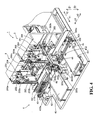
Fig. 2 is a perspective view describing details of each unit of the blood analyzer according to one embodiment shown inFig. 1 ; -
Fig. 3 is a schematic view showing a measurement unit and a specimen conveying device of the blood analyzer according to one embodiment shown inFig. 1 ; -
Fig. 4 is a perspective view showing the measurement unit and the specimen conveying device of the blood analyzer according to one embodiment shown inFig. 1 ; -
Fig. 5 is a perspective view showing a rack and a long vial of the blood analyzer according to one embodiment shown inFig. 1 ; -
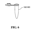
Fig. 6 is a perspective view showing a microtube of the blood analyzer according to one embodiment shown inFig. 1 ; -
Fig. 7 is a perspective view showing the vicinity of a specimen aspiration section of the blood analyzer according to one embodiment shown inFig. 1 ; -
Fig. 8 is a perspective view showing a specimen setting portion of the blood analyzer according to one embodiment shown inFig. 1 ; -
Fig. 9 is a perspective view showing the vicinity of a sample container transfer section and a fixing holder of the blood analyzer according to one embodiment shown inFig. 1 ; -
Fig. 10 is a view describing the position of the movement portion of the blood analyzer according to one embodiment shown inFig. 1 ; -
Fig. 11 is a perspective view showing the vicinity of a fixing holder of the blood analyzer according to one embodiment shown inFig. 1 ; -
Fig. 12 is a perspective view showing the vicinity of the fixing holder of the blood analyzer according to one embodiment shown inFig. 1 ; -
Fig. 13 is view describing a configuration of the fixing holder of the blood analyzer according to one embodiment shown inFig. 1 ; -
Fig. 14 is view describing the configuration of the fixing holder of the blood analyzer according to one embodiment shown inFig. 1 ; -
Fig. 15 is a plan view describing a specimen conveying device of the blood analyzer according to one embodiment shown inFig. 1 ; -
Fig. 16 is a side view describing the specimen conveying device of the blood analyzer according to one embodiment shown inFig. 1 ; -
Fig. 17 is a side view describing the specimen conveying device of the blood analyzer according to one embodiment shown inFig. 1 ; -
Fig. 18 is a block diagram describing a control device of the blood analyzer according to one embodiment shown inFig. 1 ; -
Fig. 19 is a view showing a priority specimen measurement instruction screen of the blood analyzer according to one embodiment shown inFig. 1 ; -
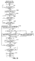
Fig. 20 is a flowchart describing a measurement processing operation by the measurement process program of the blood analyzer according to one embodiment shown inFig. 1 ; -
Fig. 21 is a flowchart describing the operation in the priority specimen measurement of the blood analyzer according to one embodiment shown inFig. 1 ; -
Fig. 22 is a state diagram describing the operation in the priority specimen measurement of the blood analyzer according to one embodiment shown inFig. 1 ; -
Fig. 23 is a state diagram describing the operation in the priority specimen measurement of the blood analyzer according to one embodiment shown inFig. 1 ; -
Fig. 24 is a state diagram describing the operation in the priority specimen measurement of the blood analyzer according to one embodiment shown inFig. 1 ; and -
Fig. 25 is a state diagram describing the operation in the priority specimen measurement of the blood analyzer according to one embodiment shown inFig. 1 . - The preferred embodiments of the present invention will be described hereinafter with reference to the drawings.
-
Fig. 1 is a perspective view showing an overall configuration of a blood analyzer according to one embodiment of the present invention.Figs. 2 to 19 are views describing the details of each unit of the blood analyzer according to one embodiment shown inFig. 1 . First, the overall configuration of theblood analyzer 1 according to one embodiment of the present invention will be described with reference toFigs. 1 to 19 . In the present embodiment, a case in which the present invention is applied to the blood analyzer serving as one example of the analyzer will be described. - In the present embodiment, as shown in
Figs. 5 and6 , asample container 100 for accommodating blood, which is a specimen, includes a long vial 101 (seeFig. 5 ), which is a specimen container of a vertically long shape, having arubber sealing lid 101a, and a microtube 102 (seeFig. 6 ), which is a specimen container for mainly accommodating a small amount of specimen, smaller than thelong vial 101. In the description of the present embodiment, description is made using "sample container 100" to include both thelong vial 101 and themicrotube 102 when corresponding to both thelong vial 101 and themicrotube 102, and description is made using the "long vial 101" or the "microtube 102" when corresponding to only one of thelong vial 101 or themicrotube 102. - As shown in
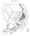
Figs. 1 and2 , theblood analyzer 1 according to the present embodiment includes two measurement units,first measurement unit 2 andsecond measurement unit 3, a specimen conveying device (sampler) 4 arranged on the front surface side (side on direction of arrow Y1) of thefirst measurement unit 2 and thesecond measurement unit 3, and acontrol device 5 including a PC (personal computer) electrically connected to thefirst measurement unit 2, thesecond measurement unit 3, and thespecimen conveying device 4. Theblood analyzer 1 is connected to a host computer 6 (seeFig. 3 ) by thecontrol device 5. - As shown in
Figs. 1 to 4 , thefirst measurement unit 2 and thesecond measurement unit 3 are measurement units of substantially the same type, and are arranged adjacent to each other. Specifically, in the present embodiment, thesecond measurement unit 3 measures the specimen for the same measurement item by using the same measurement principle as thefirst measurement unit 2. Furthermore, thesecond measurement unit 3 performs measurement on the measurement item that is not analyzed by thefirst measurement unit 2. As shown inFig. 3 , thefirst measurement unit 2 and thesecond measurement unit 3 respectively includespecimen aspiration sections sample preparation sections specimen aspiration sections detection sections sample preparation sections - Each of the
first measurement unit 2 and thesecond measurement unit 3 also includes unit covers 24, 34 for interiorly accommodating thespecimen aspiration sections sample preparation sections container conveying sections sample container 100 inside the unit covers 24, 34 and conveying thesample container 100 toaspiration positions 600, 700 (seeFig. 3 ) by thespecimen aspiration sections presence detection sections long vial 101 conveyed to the inside by the samplecontainer conveying sections fixing holders long vial 101 at theaspiration positions 600 and 700 (seeFig. 3 ). As shown inFigs. 1 and2 , on the outer surface offront surface portions close buttons measurement start buttons openings movement portions container conveying sections - As shown in
Fig. 7 , thespecimen aspiration sections pipettes pipette movement portions pipettes sealing lid 101a (seeFig. 5 ), to be hereinafter described, of thelong vial 101 can be passed through. Thepipette movement portions pipettes pipette movement portions horizontal arms pipettes screw shafts horizontal arms nuts screw shafts pipette movement portions slide rails screw shafts slidable members slide rails motors horizontal arms nuts slidable members - Pulleys 214a, 314a are attached to the upper ends of the
screw shafts stepping motors timing belts pulleys pulleys - The stepping motor 218 (318) is configured to be able to fluctuate the rotary torque according to the supplied current value (magnitude of drive pulse). The stepping motor 218 (318) is configured to lose synchronism when a load of greater than or equal to the rotary torque of the motor is applied. Specifically, the stepping motor 218 (318) is controlled such that the rotary torque becomes small when aspirating the blood accommodated in the microtube 102 (see
Fig. 6 ) compared to when aspirating the blood accommodated in the long vial 101 (seeFig. 5 ), and is configured to lose synchronism when the distal end of the pipette 211 (311) contacts the bottom portion of themicrotube 102. Thus, themicrotube 102 can be prevented from being damaged even if the distal end of the pipette 211 (311) contacts the bottom portion of themicrotube 102. The specimen accommodated in themicrotube 102 of small accommodation capacity can be aspirated barely without waste by the specimen aspiration section 21 (31) by causing the distal end of the pipette 211 (311) to reach the bottom portion of themicrotube 102. - When aspirating the blood accommodated in the
long vial 101 of larger accommodation capacity than themicrotube 102, the stepping motor 218 (318) is controlled to lower the pipette 211 (311) at a predetermined rotary torque, and after the pipette 211 (311) passes through the sealinglid 101a, to lower the pipette until the distal end reaches the vicinity of the bottom portion of thelong vial 101. In this case, the pipette 211 (311) stops the movement immediately before the distal end contacts the bottom portion of thelong vial 101, unlike to the case of themicrotube 102. Thus, when aspirating the blood accommodated in thelong vial 101, the pipette 211 (311) does not contact the bottom portion of thelong vial 101, and thus thelong vial 101 is not damaged by the pipette 211 (311). The stepping motor 218 (318) is configured such that the rotation speed fluctuates according to the frequency of the drive pulse. - The
detection sections detection sections - The detection results obtained in the
detection sections control device 5 as measurement data (measurement result) of the specimen. The measurement data is data that serves as the final analysis result (number of red blood cells, number of platelets, hemoglobin amount, number of white blood cells, and the like) provided to the user. - As shown in
Fig. 4 , the samplecontainer conveying sections hand portions long vial 101, open/close portions hand portions long vial 101,vertical movement portions hand portions portion hand portions container conveying sections container transfer sections sample container 100 in the directions of the arrows Y1 and Y2, andbarcode readers Fig. 3 . - The hand portion 251 (351) is arranged on the upper side of the conveyance path of a
rack 110 conveyed by thespecimen conveying device 4. Thehand portions long vial 101 is conveyed to afirst provision 43a and asecond provision position 43b (seeFig. 3 ), to be hereinafter described, by thespecimen conveying device 4, and then to be opened/closed by the open/close portions long vial 101 accommodated in therack 110. In this case, themovement portion 255d (355d), to be hereinafter described, of the sample container transfer section 255 (355) is accommodated on the back side (side on direction of arrow Y2) than the front surface portion 241 (341) of the unit cover 24 (34), and thus the movement to the lower side of the hand portion 251 (351) is not inhibited. - The hand portion 251 (351) is configured to take out the gripped
long vial 101 from therack 110 by moving to the upper side (direction of arrow Z1), and thereafter, to be moved (e.g., ten rounds) in the pendulum-form by the stirring portion 254 (354). The hand portion 251 (351) thus can stir the blood in the grippedlong vial 101. After terminating the stirring, the hand portion 251 (351) moves to the lower side (direction of arrow Z2), and releases the gripping of thelong vial 101 by the open/close portion 252 (352). Specifically, the hand portion 251 (351) is configured to set thelong vial 101 at a firstspecimen setting portion 255a (355a) moved to the specimen set position 610 (710) (seeFig. 3 ) by the sample container transfer section 255 (355). The hand portion 251 (351) thus can transfer thelong vial 101 from therack 101 to the firstspecimen setting portion 255a (355a) by moving thelong vial 101 in the up and down directions (direction of arrows Z1 and Z2) at substantially the same position in plan view. As shown inFig. 3 , in plan view, thefirst provision position 43a and the specimen setposition 610 are arranged to overlap, and thesecond provision position 43b and the specimen setposition 710 are arranged to overlap. - The above operation of taking out the
long vial 101 from therack 110 conveyed by thespecimen conveying device 4, and setting the same in the firstspecimen setting portion 255a (355a) is executed by controlling the steppingmotor 253a (353a) for moving the hand portion 251 (351) up and down, a steppingmotor 431e for driving afirst belt 431, and a steppingmotor 432e for driving a second belt 432 (seeFig. 4 ) by theCPU 51a to be hereinafter described. - In other words, the
CPU 51a first executes the process of conveying thelong vial 101 to thefirst provision position 43a (43b) by thespecimen conveying device 4. When themovement portion 255d (355d) is not present on the upper side of thefirst provision position 43a (43b), theCPU 51a executes the process of gripping thelong vial 101 by means of the hand portion 251 (351), raising thelong vial 101 until the lower end of thelong vial 101 is positioned on the upper side than the upper end face of the firstspecimen setting portion 255a (355a), and stirring thelong vial 101. TheCPU 51a then executes the process of moving themovement portion 255d (355d) until the firstspecimen setting portion 255a (355d) is positioned immediately below the raisedlong vial 101. TheCPU 51a executes the process of lowering the hand portion 251 (351) and releasing the gripping to set thelong vial 101 in the firstspecimen setting portion 255a (355d). TheCPU 51a then executes the process of moving themovement portion 255d (355d) until thelong vial 101 set in the firstspecimen setting portion 255a (355d) is positioned at the aspiration position 600 (700). - The open/close portion 252 (352) is configured to open/close the hand portion 251 (351) so as to grip the
long vial 101 by the power of theair cylinder 252a (352a). - The vertical movement portion 253 (353) is configured to move the hand portion 251 (351) in the vertical direction (direction of arrows Z1 and Z2) along the
rail 253b (353b) by the power of the steppingmotor 253a (353a). - The stirring portion 254 (354) is configured to move the hand portion 251 (351) in the pendulum-form in the vertical direction (direction of arrows Z1 and Z2) by the power of a stepping motor (not shown).
- As shown in
Figs. 8 and9 , samplecontainer transfer sections specimen setting portions specimen setting portions specimen setting portions movement portions adapters motors Fig. 9 ), and theannular timing belts Fig. 9 ), respectively. - As shown in
Fig. 9 , pulleys 255g and 355g are attached to the output shaft of thestepping motors belts pulleys pulleys motors motor 255e (355e) is rotatably driven, thetiming belt 255f (355f) is turned between thepulley 255g (355g) and thepulley 255h (355h). Part of thetiming belt 255f (355f) is arranged to extend in the front and back direction (direction of arrows Y1 and Y2), and themovement portion 255d (355d) is attached to the portion arranged to extend in the front and back directions of thetiming belt 255f (355f) by anattachment 255i (355i) near the back end. Themovement portion 255d (355d) then can be moved in the front and back directions (direction of arrows Y1 and Y2) with the turning of thetiming belt 255f (355f). - The first
specimen setting portion 255a (355a) attached to themovement portion 255d (355d) and the secondspecimen setting portion 255b (355b) can be moved to a predetermined position corresponding to the operation of the measurement process by controlling the rotational drive of the steppingmotor 255e (355e). Specifically, each of specimen setting portions can be arranged at the aspiration positions 600, 700, the specimen setpositions positions Fig. 3 by the samplecontainer transfer sections Fig. 3 , each position above is on the movement path of the specimen setting portion in the order of, from the front side (side on direction of arrow Y1) of theblood analyzer 1, the priority specimen set position 620 (720) arranged on the front side than the front surface portion 241 (341) of the unit cover 24 (34), the specimen set position 610 (710) arranged on the back side (side on direction of arrow Y2) than the front surface portion 241 (341), the test tube presence detection position 630 (730), and the aspiration position 600 (700). - In the present embodiment, as shown in
Fig. 3 , the sample container transfer section 255 (355) is configured to, in plan view, pass the upper side of the conveyance path of therack 110 and move each specimen setting portion to a predetermined position so that themovement portion 255d (355d) is orthogonal to the conveyance path of therack 110 conveyed by thespecimen conveying device 4. Specifically, as shown inFig. 10 , themovement portion 255d (355d) is arranged at a position H1 higher than an upper end position H2 of therack 110 conveyed by thespecimen conveying device 4, and is configured to be moved in the front and back directions (direction of arrows Y1 and 2) at substantially the horizontal direction. Each specimen setting portion attached to themovement portion 255d (355d) then can be conveyed to the predetermined position while continuing the conveying operation of therack 110 by thespecimen conveying device 4. - The first
specimen setting portions holes Fig. 8 , wherein the long vial 101 (seeFig. 5 ) can be held in the holdingholes Cutouts specimen setting portions holes barcode 101b (seeFig. 5b ) attached to thelong vial 101 can be visually recognized from the outer side with thelong vial 101 held in the firstspecimen setting portion 255a (355a). The firstspecimen setting portion 255a (355a) is removably attached to theadapter 255c (355c), and can be changed with other first specimen setting portion depending on the type of thelong vial 101. - The second
specimen setting portions upper holders lower holders specimen setting portion 255b (355b) holds the upper side of the microtube 102 (seeFig. 6 ) by the upper holder 2551 (3551), and holds the lower side of the microtube 102 (seeFig. 6 ) by thelower holder 255m (355m), so that themicrotube 102 is held at two locations of different lengths, and thus can be held in a stable state. Theupper holders holes upper holders holes portions portion 255p (355p) for supporting the portion divided into two in the left and right directions is bent in the outer side direction, the inner diameter of the holdinghole 255n (355n) can be changed, and as a result, a plurality of types ofmicrotubes 102 having different size can be held. - The
lower holders holes 255q, 355q at a position corresponding to the position of the holdingholes upper holders microtube 102 with the lower end of themicrotube 102 inserted in the holdingholes 255q, 355q, respectively. Furthermore, the secondspecimen setting portion 255b (355b) is removably attached to theadapter 255c (355c), and can be changed with other second specimen setting portion so as to respond to themicrotube 102 of the type that cannot be responded with the flexural deformation of the supportingportion 255p (355p). - The barcode reader 256 (356) is configured to read the
barcode 101b attached to eachlong vial 101, as shown inFig. 5 . The barcode reader 256 (356) is also configured to read thebarcode 101 while rotating the targetlong vial 101 in the horizontal direction by a rotating device (not shown) while being held at the firstspecimen setting portion 255a (355a). Even if thebarcode 101b of thelong vial 101 is attached to the opposite side with respect to the barcode reader 256 (356), thebarcode 101b can be directed to the barcode reader 256 (356) side by rotating thelong vial 101. Thebarcode 101b of eachlong vial 101 is uniquely attached to each specimen, and is used to manage the analysis result of each specimen, and the like. - As shown in
Fig. 3 , the presence detection section 26 (36) is arranged on the movement path of the case that the firstspecimen setting portion 255a (355a) and the secondspecimen setting portion 255b (355b) are moved from the priority specimen set position 620 (720) to the aspiration position 600 (700). - As shown in
Fig. 11 , the fixing holder 27 (37) is configured to fixedly hold thelong vial 101 transferred to the aspiration position 600 (700). As shown inFig. 12 , the fixing holder 27 (37) is configured not to fixedly hold with respect to themicrotube 102 transferred to the aspiration position 600 (700). When using themicrotube 102, themicrotube 102 is stably held using the flexural deformation of the supportingportion 255p (355p) of the secondspecimen setting portion 255b (355b), as described above, and thus the fixing holder 27 (37) does not need to be used. The fixingholders parts slidable members Figs. 11 and12 . Furthermore, the fixingholders motors annular timing belts pulleys position sensors Fig. 9 . - As shown in
Figs. 11 to 14 , the pair of sandwichingparts long vial 101 of different size, outer shape, and the like can be responded. As shown inFigs. 11 and12 , the pair of sandwiching parts 271 (371) is attached to the slidable member 273 (373) and is also attached to the timing belt 275 (375) by the coupling part 278 (378). Thus, the pair of sandwiching parts 271 (371) are moved in the horizontal direction integral with the slidable member 273 (373) with the turning of the timing belt 275 (375). The annular timing belt 275 (375) is configured to turn while being guided by the plurality of pulleys 276 (376) when the stepping motor 274 (374) is rotationally driven. As shown inFig. 9 , the annular timing belt 275 (375) is turnably stretched so as to be a predetermined shape by the plurality of pulleys 276 (376). Specifically, the timing belt 275 (375) is formed to two upper and lower stages by folding back the portion arranged extending horizontally in the directions of the arrows X1 and X2 by the pulley 276 (376). Thus, when the timing belt 275 (375) is turned, the upper portion and the lower portion of the two upper and lower stages are moved in opposite directions, directions of arrows X1 and X2, with respect to each other. - The coupling part 278 (378) attached to one of the pair of sandwiching parts 271 (371) is fixed at the upper portion of the two upper and lower stages extending horizontally in the directions of the arrows X1 and X2. The coupling part 278 (378) attached to the other of the pair of sandwiching parts 271 (371) is fixed to the lower portion of the two upper and lower stages extending horizontally in the directions of the arrows X1 and X2. Therefore, as shown in
Figs. 13 and14 , the pair of sandwiching parts 271 (371) is moved in the direction that the distance with respect to each other becomes small when the timing belt 275 (375) is turned in the direction of arrow P1, and moved in the direction that the distance with respect to each other becomes large when the timing belt 275 (375) is turned in the direction of arrow P2. Furthermore, the pair of sandwiching parts 271 (371) can be moved while maintaining the center position O of the region sandwiched by the pair of sandwiching parts 271 (371) at substantially the same position by being configured as above. Thus, the pair of sandwiching parts 271 (371) is attached to the timing belt 275 (375) by way of the coupling part 278 (378) such that the center position O of the region sandwiched by the pair of sandwiching parts 271 (371) is substantially the same position as the lowered position of the pipette 211 (311) lowered in the vertical direction when seen in plan view. The pair of sandwiching parts 271 (371) is also configured to move so as to contact from both sides while maintaining substantially the same distance with respect to thelong vial 101 transferred to the aspiration position 600 (700). Therefore, when seen in plan view, the center axis of thelong vial 101 fixedly held by the pair of sandwiching parts 271 (371) can be substantially coincided with the lowered position of the pipette 211 (311). - The position sensor 277 (377) has a cutout and is formed to a substantially U-shape. The position sensor 277 (377) is configured to detect the coupling part 278 (378) traversing the cutout. The
CPU 51a of thecontrol device 5, to be hereinafter described, can judge the position of the pair of sandwiching parts 271 (371) based on the detection result of the position sensor 277 (377), and the number of stepping of the stepping motor 274 (374). - The specimen setting portion open/close button 28 (38) is configured to be pushed by the user when performing the measurement of the priority specimen measured in preference to the continuous measurement specimen (specimen to be measured continuously) accommodated in the
long vial 101 held at therack 110. - The priority specimen measurement start button 29 (39) is configured to be pushed by the user. When the user pushes the priority specimen measurement start button 29 (39) after setting the
long vial 101 or themicrotube 102 accommodating the priority specimen in the firstspecimen setting portion 255a (355a) or thesecond setting portion 255b (355b), the setlong vial 101 or themicrotube 102 is taken into the measurement unit, and the measurement is started. - As shown in
Figs. 4 and15 , thespecimen conveying device 4 includes apre-analysis rack holder 41 capable of holding a plurality ofracks 110 accommodating thelong vial 101 for accommodating the specimen before being subjected to analysis, apost-analysis rack holder 42 capable of holding the plurality ofracks 110 accommodating thelong vial 101 for accommodating the specimen after being subjected to analysis, arack conveying unit 43 for linearly moving therack 110 horizontally in the directions of the arrows X1 and X2, abarcode reader 44, a presence detection sensor 45 (seeFig. 4 ) for detecting the presence of thelong vial 101, and a rack feed-outunit 46 for moving therack 110 into thepost-analysis rack holder 42. - The
pre-analysis rack holder 41 includes a rack feed-inunit 411, where therack 110 held by thepre-analysis rack holder 41 is pushed out onto therack conveying unit 43 one at a time when the rack feed-inunit 411 moves in the direction of arrow Y2. The rack feed-inunit 411 is configured to be driven by a stepping motor (not shown) arranged at the lower side of thepre-analysis rack holder 41. Thepre-analysis rack holder 41 has a regulating part 412 (seeFig. 4 ) in the vicinity of therack conveying unit 43, and is configured to regulate the movement of therack 110 so that therack 110 that has once been pushed out onto therack conveying unit 43 does not return to thepre-analysis rack holder 41. - The
post-analysis rack holder 42 has a regulating part 421 (seeFig. 4 ) in the vicinity of therack conveying unit 43, and is configured to regulate the movement of therack 110 so that therack 110 that has once been moved into thepost-analysis rack holder 42 does not return to therack conveying unit 43 side. - As shown in
Fig. 3 , therack conveying unit 43 is configured to be able to convey therack 110 such that the specimen is conveyed to thefirst provision position 43a for providing the specimen to thefirst measurement unit 2 and thesecond provision position 43b for providing the specimen to thesecond measurement unit 3. Furthermore, therack conveying unit 43 is configured to be able to convey therack 110 such that the specimen is conveyed to a specimenpresence check position 43c for thepresence detection sensor 45 to check the presence of thesample container 100 for accommodating the specimen and aread position 43d for thebarcode reader 44 to read thebarcode 101b (seeFig. 5 ) of thelong vial 101 accommodating the specimen. - As shown in
Figs. 4 and15 , therack conveying unit 43 includes two belts,first belt 431 andsecond belt 432, which can move independent from each other. The widths b1 and b2 (seeFig. 15 ) in the directions of the arrows Y1 and Y2 of thefirst belt 431 and thesecond belt 432 have a magnitude of smaller than or equal to half of the width B of the directions of the arrows Y1 and Y2 of therack 110, respectively. Thus, when therack conveying unit 43 conveys therack 110, thefirst belt 431 and thesecond belt 432 are both arranged in parallel so as not to exceed the width B of therack 110. As shown inFigs. 16 and17 , thefirst belt 431 and thesecond belt 432 are formed to an annular shape, and are arranged so as to surround therollers rollers pieces first belt 431 and thesecond belt 432 so as to have an inner width w1 (seeFig. 16 ) and w2 (seeFig. 17 ) slightly (e.g., about 1mm) larger than the width W in the directions of the arrows X1 and X2 of therack 110. Thefirst belt 431 is configured to move therack 110 in the directions of the arrows X1 and X2 by being moved at the outer periphery of therollers 431a to 431c by the steppingmotor 431e (seeFig. 4 ) with therack 110 held at the inner side of the projectingpiece 431d. Thesecond belt 432 is configured to move therack 110 in the directions of the arrows X1 and X2 by being moved at the outer periphery of therollers 432a to 432c by the steppingmotor 432e (seeFig. 4 ) with therack 110 held at the inner side of the projectingpiece 432d. Thefirst belt 431 and thesecond belt 432 are each configured to be able to move therack 110 independent from each other. - The
barcode reader 44 is configured to read thebarcode 101b attached to eachlong vial 101 shown inFig. 5 , and to read thebarcode 110a attached to therack 110. Thebarcode reader 44 is also configured to read thebarcode 101 while rotating the targetlong vial 101 in the horizontal direction by a rotating device (not shown) while being accommodated in therack 110. Thus, even if thebarcode 101b of thelong vial 101 is attached to the opposite side with respect to thebarcode reader 44, thebarcode 101b can be directed to thebarcode reader 44 side by rotating thelong vial 101. Thebarcode 110a of therack 110 is uniquely attached to each rack, and is used to manage the analysis result of the specimen, and the like. - The
presence detection sensor 45 is a contact type sensor, and includes a curtain-shaped contact piece 451 (seeFig. 4 ), a light emitting element (not shown) for emitting light, and a light receiving element (not shown). Thepresence detection sensor 45 is configured such that thecontact piece 451 is bent by contacting a detecting object to be detected, and as a result, the light exited from the light emitting element is reflected by thecontact piece 451 and entered to the light receiving element. Therefore, when thelong vial 101 to be detected accommodated in therack 110 passes the lower side of thepresence detection sensor 45, thecontact piece 451 is bent by thelong vial 101, and the presence of thelong vial 101 can be detected. - The rack feed-out
unit 46 is arranged so as to face thepost-analysis rack holder 42 with therack conveying unit 43 in between, and is configured to move horizontally in the direction of arrow Y1. Thus, when therack 110 is conveyed to between thepost-analysis rack holder 42 and the rack feed-outunit 46, therack 110 is pushed and moved into thepost-analysis rack holder 42 by moving the rack feed-outunit 46 to thepost-analysis rack holder 42 side. - As shown in
Figs. 1 to 3 and18 , thecontrol device 5 is configured by a personal computer (PC) and the like, and includes a control unit 51 (seeFig. 18 ) including CPU, ROM, and RAM, adisplay unit 52, and aninput device 53. Thedisplay unit 52 is arranged to display the analysis result and the like obtained by analyzing the data of the digital signal transmitted from thefirst measurement unit 2 and thesecond measurement unit 3. As shown inFig. 19 , thedisplay unit 52 is configured to display a priority specimenmeasurement instruction screen 520 for the user to perform input of a specimen identification number for identifying the specimen, measurement item setting, and the like in the measurement of the priority specimen that needs to be measured in preference to other specimens. - The configuration of the
control device 5 will now be described. As shown inFig. 18 , thecontrol device 5 is configured by acomputer 500 mainly configured by acontrol unit 51, adisplay unit 52, and aninput device 53. Thecontrol unit 51 is mainly configured by aCPU 51a, aROM 51b, aRAM 51c, ahard disc 51d, a read-outdevice 51e, an input/output interface 51f, acommunication interface 51g, and animage output interface 51h. TheCPU 51a, theROM 51b, theRAM 51c, thehard disc 51d, the read-outdevice 51e, the input/output interface 51f, thecommunication interface 51g, and theimage output interface 51h are connected by abus 51i. - The
CPU 51a can execute computer programs stored in theROM 51b and the computer programs loaded in theRAM 51c. Thecomputer 500 serves as thecontrol device 5 when theCPU 51a executes theapplication programs - The
ROM 51b is configured by mask ROM, PROM, EPROM, EEPROM, and the like, and is recorded with computer programs to be executed by theCPU 51a, data used for the same, and the like. - The
RAM 51c is configured by SRAM, DRAM, and the like. TheRAM 51c is used to read out the computer programs recorded on theROM 51b and thehard disc 51d. TheRAM 51c is used as a work region of theCPU 51a when executing the computer programs. - The
hard disc 51d is installed with various computer programs to be executed by theCPU 51a such as operating system and application program, as well as data used in executing the computer program. The measurement process (1)program 54a for thefirst measurement unit 2, the measurement process (2)program 54b for thesecond measurement unit 3, and the sampleoperation process program 54c for thespecimen conveying device 4 are also installed in thehard disc 51d. When theCPU 51a executessuch application programs 54a to 54c, the operation of each portion of thefirst measurement unit 2, thesecond measurement unit 3, and thespecimen conveying device 4 is controlled. Themeasurement result database 54d is also installed in thehard disc 51d. - The read-out
device 51e is configured by flexible disc drive, CD-ROM drive, DVD-ROM drive, and the like, and is able to read out computer programs and data recorded on aportable recording medium 54. Theapplication programs 54a to 54c are stored in theportable recording medium 54, wherein thecomputer 500 reads out theapplication programs 54a to 54c from theportable recording medium 54, and installs theapplication programs 54a to 54c in thehard disc 51d. - The
application programs 54a to 54c are not only provided by theportable recording medium 54, but are also provided through communication line (wired or wireless) from external devices communicably connected with thecomputer 500 through the communication line. For instance, theapplication programs 54a to 54c may be stored in the hard disc of the server computer on Internet, so that thecomputer 500 can access the server computer to download theapplication programs 54a to 54c and install the same in thehard disc 51d. - Operating system providing graphical user interface environment such as Windows (registered trademark) manufactured and sold by US Microsoft Co. is installed in the
hard disc 51d. In the following description, theapplication programs 54a to 54c are assumed to operate on the operating system. - The input/
output interface 51f is configured by serial interface such as USB, IEEE1394, RS-232C; parallel interface such as SCSI, IDE, IEEE1284; analog interface such as D/A converter, A/D converter, and the like. Theinput device 53 is connected to the input/output interface 51f, so that the user can input data to thecomputer 500 by using theinput device 53. - The
communication interface 51g is, for example, Ethernet (registered trademark) interface. Thecomputer 500 transmits and receives data with thefirst measurement unit 2, thesecond measurement unit 3, thespecimen conveying device 4, and the host computer 6 by using a predetermined communication protocol by means of thecommunication interface 51g. - The
image output interface 51h is connected to thedisplay unit 52 configured by LCD, CRT, or the like, and is configured to output an image signal corresponding to the image data provided from theCPU 51a to thedisplay unit 52. Thedisplay unit 52 displays the image (screen) according to the input image signal. - According to the above configuration, the
control unit 51 analyzes the component to be analyzed using the measurement results transmitted from thefirst measurement unit 2 and thesecond measurement unit 3, and acquires the analysis result (number of red blood cells, number of platelets, amount of hemoglobin, number of white blood cells, and the like). - As shown in
Fig. 5 , therack 110 is formed with tencontainer accommodating portions 110b so as to accommodate tensample containers 100 in a line. Eachcontainer accommodating portion 110b is provided with anopening 110c such that thebarcode 101b of the accommodatedlong vial 101 can be visually recognized. -
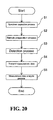
Fig. 20 is a flowchart describing the measurement processing operation by the measurement process program of the blood analyzer according to one embodiment shown inFig. 1 . The measurement processing operation by themeasurement process programs blood analyzer 1 according to one embodiment will be described with reference toFigs. 3 and20 . The component to be analyzed is similarly measured in thefirst measurement unit 2 and thesecond measurement unit 3, and thus a case of measuring the component to be analyzed by thefirst measurement unit 2 will be described below as a representative example. - First, in step S1, the specimen is aspirated by the
specimen aspiration section 21 from thesample container 100 conveyed to theaspiration position 600 shown inFig. 3 . In step S2, the detection sample is prepared by thesample preparation section 22 from the aspirated specimen, and in step S3, the component to be analyzed is detected by thedetection section 23 from the detection sample. In step S4, the measurement data is transmitted from thefirst measurement unit 2 to thecontrol device 5. Thereafter, in step S5, the component to be analyzed by thecontrol unit 51 is analyzed based on the measurement result transmitted from thefirst measurement unit 2. The analysis of the specimen is completed and the operation is terminated by step S5. -
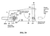
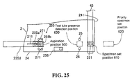
Fig. 21 is a flowchart describing the operation in the priority specimen measurement of the blood analyzer according to one embodiment shown inFig. 1 .Figs. 22 to 25 are state diagrams for describing the operation in the priority specimen measurement of the blood analyzer according to one embodiment shown inFig. 1 . The operation in the priority specimen measurement of theblood analyzer 1 according to one embodiment will be described below with reference toFigs. 1 ,2 ,19 , and21 to 25 . In the present embodiment, thefirst measurement unit 2 and thesecond measurement unit 3 can measure the priority specimen independent from each other, and the operations in the priority specimen measurement in thefirst measurement unit 2 and thesecond measurement unit 3 are the same. Therefore, the operations in the priority specimen measurement in thefirst measurement unit 2 will be described herein as a representative example. - First, in step S101 shown in
Fig. 21 , theCPU 51a judges whether or not the specimen setting portion open/close button 28 (seeFigs. 1 and2 ) is pushed, and repeats the judgment until the button is pushed. When the button is pushed, themovement portion 255d is moved so as to project out from thefront surface portion 241 of theunit cover 24, and the firstspecimen setting portion 255a and the secondspecimen setting portion 255b are arranged at the priority specimen setposition 620 in step S102, as shown inFig. 22 . - In step S103, the priority specimen
measurement instruction screen 520 is displayed on thedisplay unit 52, as shown inFig. 19 . In step S104, the user inputs the specimen identification number and sets the measurement items, and thereafter, theCPU 51a judges whether or not theOK button 520a displayed on the priority specimenmeasurement instruction screen 520 is pushed. This judgment is continued until theOK button 520a is pushed. When the cancelbutton 520b is pushed, the priority specimenmeasurement instruction screen 520 is terminated. When theOK button 520a of the priority specimenmeasurement instruction screen 520 is pushed, theCPU 51a judges whether or not the priority specimen measurement start button 29 (seeFigs. 1 and2 ) is pushed in step S105. The user sets thelong vial 101 or themicrotube 102 accommodating the priority specimen in the firstspecimen setting portion 255a or the second specimen setting portion 522b after pushing theOK button 520a, and then pushes the priority specimenmeasurement start button 29. This judgment is repeated if the priority specimenmeasurement start button 29 is not pushed, and if the button is pushed, the firstspecimen setting portion 255a is moved to the test tubepresence detection position 630, and the presence of thelong vial 101 is detected by thepresence detection section 26 in step S106, as shown inFig. 23 . The user sets themicrotube 102 in the secondspecimen setting portion 255b with the lid of themicrotube 102 detached when measuring the priority specimen accommodated in themicrotube 102. - In step S107, the
CPU 51a judges whether or not thelong vial 101 is set in the firstspecimen setting portion 255a based on the detection result, where the firstspecimen setting portion 255a is moved to theaspiration position 600 if thelong vial 101 is set in step S108, as shown inFig. 24 . Thereafter, thelong vial 101 held by the firstspecimen setting portion 255a is sandwiched by the pair of sandwichingparts 271 of the fixingholder 27, and thelong vial 101 is fixedly held such that the center axis of thelong vial 101 is at the lowered position of thepipette 211. Thepipette 211 is passed through the sealinglid 101a, and inserted to the inside of thelong vial 101. Specifically, thepipette 211 is lowered by the steppingmotor 218, which is rotatably driven at a predetermined rotary torque, passed through the sealinglid 101a, and thereafter, lowered until the distal end reaches the vicinity of the bottom portion of thelong vial 101. After the blood in thelong vial 101 is aspirated by thespecimen aspiration section 21, the measurement of the priority specimen is performed in step S110. - If the
CPU 51a judges that thelong vial 101 is not set in the firstspecimen setting portion 255a in step S107, the secondspecimen setting portion 255b is moved to theaspiration position 600 in step S109, as shown inFig. 25 . Thepipette 211 is inserted to the inside of themicrotube 102 held at the secondspecimen setting portion 255b, and lowered until the distal end reaches the bottom portion of themicrotube 102. After the aspiration operation of the blood by thespecimen aspiration section 21 is performed in this state, the process proceeds to step S110, and the measurement of the priority specimen is performed. The aspirating amount of blood in step S109 is less than the aspirating amount of blood in step S108. - After the aspiration of blood is completed, the first
specimen setting portion 255a and the secondspecimen setting portion 255b are moved to the priority specimen setposition 620 by the samplecontainer transfer section 255 in step S111, as shown inFig. 22 . Thereafter, whether or not the priority specimenmeasurement start button 29 is pushed is judged in step S112. The user removes thelong vial 101 or themicrotube 102, where the blood has been aspirated, from the firstspecimen setting portion 255a or the secondspecimen setting portion 255b, then sets thelong vial 101 or themicrotube 102 accommodating a new priority specimen in the firstspecimen setting portion 255a or the secondspecimen setting portion 255b, and pushes the priority specimenmeasurement start button 29 to continuously perform the measurement of the priority specimen. When the user sets thelong vial 101 or themicrotube 102 accommodating the new priority specimen in the firstspecimen setting portion 255a or the secondspecimen setting portion 255b, and pushes the priority specimenmeasurement start button 29, the operation proceeds to step S106, and the measurement of the next priority specimen is continuously performed. - If the priority specimen
measurement start button 29 is not pushed, theCPU 51a judges whether or not the specimen setting portion open/close button 28 is pushed in step S113. The user can terminate the measurement of the priority specimen by pushing the specimen setting portion open/close button 28. If the specimen setting portion open/close button 28 is not pushed, the judgments are repeated until either the priority specimenmeasurement start button 29 or the specimen setting portion open/close button 28 is pushed. If the specimen setting portion open/close button 28 is pushed, themovement portion 255d is moved in the direction of arrow Y2 to return the firstspecimen setting portion 255a and the secondspecimen setting portion 255b inside theunit cover 24 of thefirst measurement unit 2 in step S114, and the measurement operation of the priority specimen is terminated. - In the present embodiment, a plurality of
specimen containers 100 of different types can be responded by arranging the firstspecimen setting portion 255a (355a) and the secondspecimen setting portion 255b (355b) for holding the a plurality ofspecimen containers 100 of different types (long vial 101 and microtube 102), as described above. With the arrangement of the presence detection section 26 (36) for detecting the presence of thelong vial 101 set in the firstspecimen setting portion 255a (355a), and theCPU 51a for determining in which specimen setting portion, of the first specimen setting portion 255 (355a) or the secondspecimen setting portion 255b (355b), thesample container 100 is set based on the detection result of the presence detection section 26 (36), and controlling the operation of the specimen aspiration section 21 (31), the aspirating operation corresponding to the specimen setting portion set with thesample container 100 can be automatically carried out by theCPU 51a based on the detection result of the presence detection section 26 (36) regardless of whether thesample container 100 is set in first specimen setting portion 255 (355a) or the secondspecimen setting portion 255b (355b), and thus the user does not need to separately perform the operation of manually moving the container holder to set thesample container 100 when setting thesample container 100. Therefore, the burden on the user when setting thesample container 100 can be alleviated while responding to the plurality ofspecimen containers 100 of different types. - In the present embodiment, the
CPU 51a is configured to control the operation of the sample container transfer section 255 (355) so that thesample container 100 set in either the firstspecimen setting portion 255a (355a) or the secondspecimen setting portion 255b (355b) is moved to the aspiration position 600 (700) based on the detection result of the presence detection section 26 (36), so that theset sample container 100 is moved to the aspiration position 600 (700) based on the detection result of the presence detection section 26 (36) irrespective of which specimen setting portion, the firstspecimen setting portion 255a (355a) or the secondspecimen setting portion 255b (355b), thesample container 100 is set, whereby the user does not need to separately perform the operation of moving thesample container 100 to the aspiration position 600 (700) when setting thesample container 100. Therefore, the burden on the user when setting thesample container 100 can be easily alleviated. - In the present embodiment, the fixing holder 27 (37) is arranged with a pair of sandwiching parts 271 (371) for fixing and holding the
long vial 101 set in the firstspecimen setting portion 255a (355a) by sandwiching from the periphery, and the pair of sandwiching parts 271 (371) is configured to move towards the setlong vial 101 to sandwich thelong vial 101 with the center position O of the region to be sandwiched by the pair of sandwiching parts 271 (371) maintained at substantially the same position, whereby the operation of aspirating the specimen can be reliably carried out since the center axis of the setlong vial 101 is arranged at the center position O of the region to be sandwiched by the pair of sandwiching parts 271 (371) maintained at substantially the same position at the aspiration position 600 (700) even if along vial 101 of different size is set. - In the present embodiment, the first
specimen setting portion 255a (355a), and the secondspecimen setting portion 255b (355b) set with themicrotube 102 having a smaller size than thelong vial 101 set in the firstspecimen setting portion 255a (355a) are arranged, wherein the specimen in themicrotube 102 having smaller accommodation capacity than thelong vial 101 can be aspirated without waste by configuring theCPU 51a so as to control the pipette movement portion 212 (312) to move the pipette 211 (311) to a position closer to the bottom of the container in the case that the specimen aspiration section 21 (31) aspirates the specimen from themicrotube 102 held in the secondspecimen setting portion 255b (355b) than the case that the aspiration section 21 (31) aspirates the specimen from thelong vial 101. - The embodiment disclosed herein is merely illustrative in all aspects and should not be recognized as being restrictive. The scope of the invention is defined by the claims rather than the description of the embodiment as described above, and the meaning equivalent to the claims and all modifications within the scope are encompassed therein.
- For instance, the blood analyzer is described as one example of an analyzer in the present embodiment, but the present invention is not limited thereto, and the present invention may be applied to other analyzers as long as the measurement of both the continuous measurement specimen and the priority specimen can be responded.
- Furthermore, an analyzer including two measurement units of the first measurement unit and the second measurement unit is described as one example of an analyzer in the present embodiment, but the present invention is not limited thereto, and may be an analyzer including one measurement unit or an analyzer including three or more measurement units.
- The CPU, which is one of the control device, for controlling the respective section and portion of both the first measurement unit and the second measurement unit, is described in the present embodiment, but the present invention is not limited thereto, and a plurality of CPUs for controlling the respective section and portion of the first measurement unit and the second measurement unit independently may be provided.
- The priority specimen holder including two specimen setting portions, the first specimen setting portion and the second specimen setting portion, has been described as one example of a specimen container setting portion in the present embodiment, but the present invention is not limited thereto, and may be a specimen container setting portion including three or more specimen setting portions.
- The analyzer having a configuration of moving the specimen container setting portion from the specimen set position to the aspiration position by the sample container transfer section has been described as one example of an analyzer in the present embodiment, but the present invention is not limited thereto, and may be an analyzer having a configuration of allowing the user to move the specimen container setting portion from the specimen set position to the aspiration position.
- The presence detection section for detecting the presence of the long vial has been described as one example of a detection section in the present embodiment, but the present invention is not limited thereto, and may be a detection section for detecting the presence of a microtube, or may be a detection section for detecting the presence of both the long vial and the microtube. Furthermore, two detection sections may be arranged, and the long vial and the microtube may be detected by different detection sections.
- The fixing holder for fixing and holding the long vial has been described as one example of a fixing holder in the present embodiment, but the present invention is not limited thereto, and may be a fixing holder for fixing and holding both the long vial and the microtube.
- The analyzer equipped with the specimen conveying device has been described as one example of an analyzer in the present embodiment, but the present invention is not limited thereto, and may be an analyzer not equipped with the specimen conveying device.
- The hand portion configured to move in the up and down direction (directions of arrows Z1 and Z2) at substantially the same position in plan view has been described as one example of a container transferring mechanism in the present embodiment, but the present invention is not limited thereto, and may be a container transferring mechanism configured to move in a direction tilted with respect to the up and down direction as long as the specimen container can be transferred from the continuous measurement specimen holder to the container holder.
- The specimen aspiration section configured to adjust the lowering amount (lowered position) of the pipette depending on the type of specimen container has been described as one example of an aspiration section in the present embodiment, but the present invention is not limited thereto, and may be an aspiration section configured to adjust the aspirating amount of the specimen depending on the type of specimen container.
Claims (15)
- An analyzer comprising:a specimen container setting portion including a plurality of container holders for holding a plurality of specimen containers of different types;an aspiration section for aspirating the specimen from the specimen container set in the specimen container setting portion;a sensor for detecting the presence of the specimen container set in at least one of the plurality of container holders; anda controller for determining in which of the plurality of container holders the specimen container is set based on the detection result of the sensor, and controlling the operation of the aspiration section.
- The analyzer according to claim 1, further comprising a moving assembly for moving the specimen container setting portion to a specimen set position at which the specimen container is set and an aspiration position at which the specimen is aspirated by the aspiration section.
- The analyzer according to claim 2, wherein the controller further controls the operation of the moving assembly so that the specimen container set in one of the plurality of container holders is moved to the aspiration position based on the detection result of the sensor.
- The analyzer according to claim 2 or 3, wherein the sensor is arranged at a position of detecting the specimen container disposed on a path from the specimen set position to the aspiration position.
- The analyzer according to any one of claims 2 to 4, further comprising an aspiration position holding portion for tightly holding the specimen container set in the container holder at the aspiration position.
- The analyzer according to claim 5, wherein
the aspiration position holding portion includes a pair of sandwiching parts for holding the specimen container set in the container holder by sandwiching from the periphery; and
the pair of sandwiching parts is configured to sandwich the specimen container by moving towards the set specimen container with the center position of the region to be sandwiched by the pair of sandwiching parts maintained at substantially the same position. - The analyzer according to any one of claims 1 to 6, wherein
the aspiration section includes a pipette and a pipette moving assembly for moving the pipette up and down; and
the controller controls the movement of the pipette by the pipette moving assembly based on the detection result of the sensor. - The analyzer according to claim 7, wherein
the plurality of container holders include a first container holder, and a second container holder to be set with a specimen container of smaller volume than the specimen container to be set in the first container holder; and
the controller controls the pipette moving assembly to move the pipette to a position closer to the bottom of the specimen container in the case that the aspiration section aspirates the specimen from the specimen container held in the second container holder than the case that the aspiration section aspirates the specimen from the specimen container held in the first container holder. - The analyzer according to claim 8, wherein the controller controls the pipette moving assembly so that the pipette reaches the bottom of the specimen container when the aspiration section aspirates the specimen from the specimen container held in the second container holder.
- The analyzer according to any one of claims 1 to 7, wherein
the plurality of container holders include a first container holder, and a second container holder to be set with a specimen container of smaller volume than the specimen container to be set in the first container holder; and
the second container holder is arranged on the front side of the analyzer than the first container holder. - The analyzer according to any one of claims 1 to 10, wherein the controller controls an aspirating amount of the specimen by the aspiration section based on the detection result of the sensor.
- The analyzer according to any one of claims 1 to 11, wherein
the specimen container setting portion includes two container holders;
the sensor detects the presence of the specimen container set in either one of the two container holders; and
the controller determines in which of the two container holders the specimen container is set based on the presence of the specimen container, and controls the operation of the aspiration section. - The analyzer according to any one of claims 1 to 12, further comprising:a continuous measurement specimen holder configured to hold a plurality of specimen containers accommodating a continuous measurement specimen to be continuously measured; anda container transferring assembly for transferring the specimen container accommodating the continuous measurement specimen from the continuous measurement specimen holder to the container holder; whereinthe aspiration section is configured to aspirate the continuous measurement specimen.
- An analyzer comprising:a specimen container setting portion including a plurality of container holders for holding a plurality of specimen containers of different types;an aspiration section for aspirating the specimen from the specimen container set in the specimen container setting portion;a moving assembly for moving the specimen container setting portion to a specimen set position at which the specimen container is set and an aspiration position at which the specimen is aspirated by the aspiration section;a sensor for detecting the presence of the specimen container set in at least one of the plurality of container holders; anda controller for controlling the operation of the moving assembly so that the specimen container set in one of the plurality of container holders is moved to the aspiration position based on the detection result of the sensor.
- A method for aspirating a specimen comprising:receiving a specimen container in one of a plurality of container holders for holding a plurality of specimen containers of different types;moving a predetermined container holder of the plurality of container holders to a detection position by a sensor for detecting the presence of the specimen container;detecting the presence of the specimen container by the sensor;determining a movement distance of the container holder the received specimen container moves to an aspiration position of the specimen by an aspiration section based on the detection result of the sensor;moving the container holder according to the determined movement distance; andaspirating the specimen from the specimen container by the aspiration section.
Applications Claiming Priority (6)
| Application Number | Priority Date | Filing Date | Title |
|---|---|---|---|
| JP2008057661A JP5198095B2 (en) | 2008-03-07 | 2008-03-07 | Analysis apparatus and analysis method |
| JP2008058302A JP5198096B2 (en) | 2008-03-07 | 2008-03-07 | Analysis equipment |
| JP2008057382A JP5198094B2 (en) | 2008-03-07 | 2008-03-07 | Analysis equipment |
| JP2008058007A JP5192263B2 (en) | 2008-03-07 | 2008-03-07 | Analytical apparatus and sample transport method |
| JP2008057972A JP5289798B2 (en) | 2008-03-07 | 2008-03-07 | Analytical apparatus and sample transport method |
| JP2008169906A JP5166996B2 (en) | 2008-06-30 | 2008-06-30 | Analysis equipment |
Publications (3)
| Publication Number | Publication Date |
|---|---|
| EP2098872A2 true EP2098872A2 (en) | 2009-09-09 |
| EP2098872A3 EP2098872A3 (en) | 2015-04-15 |
| EP2098872B1 EP2098872B1 (en) | 2021-12-01 |
Family
ID=40513388
Family Applications (1)
| Application Number | Title | Priority Date | Filing Date |
|---|---|---|---|
| EP09003332.5A Active EP2098872B1 (en) | 2008-03-07 | 2009-03-06 | Analyzer and method for aspirating specimen |
Country Status (1)
| Country | Link |
|---|---|
| EP (1) | EP2098872B1 (en) |
Cited By (2)
| Publication number | Priority date | Publication date | Assignee | Title |
|---|---|---|---|---|
| US9057672B2 (en) | 2011-07-22 | 2015-06-16 | Roche Diagnostics Hematology, Inc. | Fluid sample preparation systems and methods |
| CN113198560A (en) * | 2021-05-06 | 2021-08-03 | 佳木斯大学 | Blood specimen test tube rack and identification alarm method |
Citations (1)
| Publication number | Priority date | Publication date | Assignee | Title |
|---|---|---|---|---|
| JPH11295321A (en) | 1998-04-11 | 1999-10-29 | Horiba Ltd | Device for supporting specimen container of specimen inspection device |
Family Cites Families (6)
| Publication number | Priority date | Publication date | Assignee | Title |
|---|---|---|---|---|
| JPH01219669A (en) * | 1988-02-29 | 1989-09-01 | Shimadzu Corp | Detecting method of liquid sample vessel according to assortment |
| JP3032159B2 (en) * | 1996-09-24 | 2000-04-10 | 株式会社日立製作所 | Analysis system |
| AUPP058197A0 (en) * | 1997-11-27 | 1997-12-18 | A.I. Scientific Pty Ltd | Pathology sample tube distributor |
| US6919044B1 (en) * | 1999-06-17 | 2005-07-19 | Beckman Coulter, Inc. | Sample loading and handling interface to multiple chemistry analyzers |
| EP1767274B1 (en) * | 2005-09-26 | 2015-09-09 | QIAGEN GmbH | Method for processing a fluid |
| JP4980671B2 (en) * | 2006-08-18 | 2012-07-18 | シスメックス株式会社 | Blood sample analyzer |
-
2009
- 2009-03-06 EP EP09003332.5A patent/EP2098872B1/en active Active
Patent Citations (1)
| Publication number | Priority date | Publication date | Assignee | Title |
|---|---|---|---|---|
| JPH11295321A (en) | 1998-04-11 | 1999-10-29 | Horiba Ltd | Device for supporting specimen container of specimen inspection device |
Cited By (4)
| Publication number | Priority date | Publication date | Assignee | Title |
|---|---|---|---|---|
| US9057672B2 (en) | 2011-07-22 | 2015-06-16 | Roche Diagnostics Hematology, Inc. | Fluid sample preparation systems and methods |
| US9588026B2 (en) | 2011-07-22 | 2017-03-07 | Roche Diagnostics Hematology, Inc. | Fluid sample preparation systems and methods |
| US10345205B2 (en) | 2011-07-22 | 2019-07-09 | Roche Diagnostics Hematology, Inc. | Fluid sample preparation systems and methods |
| CN113198560A (en) * | 2021-05-06 | 2021-08-03 | 佳木斯大学 | Blood specimen test tube rack and identification alarm method |
Also Published As
| Publication number | Publication date |
|---|---|
| EP2098872B1 (en) | 2021-12-01 |
| EP2098872A3 (en) | 2015-04-15 |
Similar Documents
| Publication | Publication Date | Title |
|---|---|---|
| US8097211B2 (en) | Analyzer | |
| US8343770B2 (en) | Analyzer and method for aspirating specimen | |
| EP3650865B1 (en) | Transportation device | |
| JP5315044B2 (en) | Sample testing equipment | |
| JP5355362B2 (en) | Specimen inspection system, specimen inspection method and computer program | |
| JP5192263B2 (en) | Analytical apparatus and sample transport method | |
| US8143065B2 (en) | Specimen processing device, specimen conveyance device, and specimen conveyance method | |
| EP2306206B1 (en) | Blood sample processing apparatus and blood sample processing method | |
| EP1857820A2 (en) | Sample analyzer | |
| EP2703819B1 (en) | Sample processing apparatus and sample processing method | |
| JP5319239B2 (en) | Specimen processing apparatus and specimen aspirating apparatus | |
| EP2098872B1 (en) | Analyzer and method for aspirating specimen | |
| EP2098870B1 (en) | Analyzer | |
| US8594836B2 (en) | Sample processing system, sample processing method, and computer program product | |
| EP2199804B1 (en) | Sample processing system, sample processing method, and computer program product |
Legal Events
| Date | Code | Title | Description |
|---|---|---|---|
| PUAI | Public reference made under article 153(3) epc to a published international application that has entered the european phase |
Free format text: ORIGINAL CODE: 0009012 |
|
| AK | Designated contracting states |
Kind code of ref document: A2 Designated state(s): AT BE BG CH CY CZ DE DK EE ES FI FR GB GR HR HU IE IS IT LI LT LU LV MC MK MT NL NO PL PT RO SE SI SK TR |
|
| AX | Request for extension of the european patent |
Extension state: AL BA RS |
|
| PUAL | Search report despatched |
Free format text: ORIGINAL CODE: 0009013 |
|
| AK | Designated contracting states |
Kind code of ref document: A3 Designated state(s): AT BE BG CH CY CZ DE DK EE ES FI FR GB GR HR HU IE IS IT LI LT LU LV MC MK MT NL NO PL PT RO SE SI SK TR |
|
| AX | Request for extension of the european patent |
Extension state: AL BA RS |
|
| RIC1 | Information provided on ipc code assigned before grant |
Ipc: G01N 35/10 20060101ALI20150311BHEP Ipc: B01L 9/06 20060101ALI20150311BHEP Ipc: G01N 35/00 20060101AFI20150311BHEP Ipc: G01N 35/02 20060101ALI20150311BHEP Ipc: G01N 35/04 20060101ALI20150311BHEP |
|
| 17P | Request for examination filed |
Effective date: 20150928 |
|
| RBV | Designated contracting states (corrected) |
Designated state(s): AT BE BG CH CY CZ DE DK EE ES FI FR GB GR HR HU IE IS IT LI LT LU LV MC MK MT NL NO PL PT RO SE SI SK TR |
|
| AKX | Designation fees paid |
Designated state(s): AT BE BG CH CY CZ DE DK EE ES FI FR GB GR HR HU IE IS IT LI LT LU LV MC MK MT NL NO PL PT RO SE SI SK TR |
|
| STAA | Information on the status of an ep patent application or granted ep patent |
Free format text: STATUS: EXAMINATION IS IN PROGRESS |
|
| 17Q | First examination report despatched |
Effective date: 20190621 |
|
| STAA | Information on the status of an ep patent application or granted ep patent |
Free format text: STATUS: EXAMINATION IS IN PROGRESS |
|
| GRAP | Despatch of communication of intention to grant a patent |
Free format text: ORIGINAL CODE: EPIDOSNIGR1 |
|
| STAA | Information on the status of an ep patent application or granted ep patent |
Free format text: STATUS: GRANT OF PATENT IS INTENDED |
|
| INTG | Intention to grant announced |
Effective date: 20210310 |
|
| GRAJ | Information related to disapproval of communication of intention to grant by the applicant or resumption of examination proceedings by the epo deleted |
Free format text: ORIGINAL CODE: EPIDOSDIGR1 |
|
| STAA | Information on the status of an ep patent application or granted ep patent |
Free format text: STATUS: EXAMINATION IS IN PROGRESS |
|
| GRAP | Despatch of communication of intention to grant a patent |
Free format text: ORIGINAL CODE: EPIDOSNIGR1 |
|
| STAA | Information on the status of an ep patent application or granted ep patent |
Free format text: STATUS: GRANT OF PATENT IS INTENDED |
|
| INTG | Intention to grant announced |
Effective date: 20210723 |
|
| GRAS | Grant fee paid |
Free format text: ORIGINAL CODE: EPIDOSNIGR3 |
|
| GRAA | (expected) grant |
Free format text: ORIGINAL CODE: 0009210 |
|
| STAA | Information on the status of an ep patent application or granted ep patent |
Free format text: STATUS: THE PATENT HAS BEEN GRANTED |
|
| AK | Designated contracting states |
Kind code of ref document: B1 Designated state(s): AT BE BG CH CY CZ DE DK EE ES FI FR GB GR HR HU IE IS IT LI LT LU LV MC MK MT NL NO PL PT RO SE SI SK TR |
|
| REG | Reference to a national code |
Ref country code: GB Ref legal event code: FG4D |
|
| REG | Reference to a national code |
Ref country code: AT Ref legal event code: REF Ref document number: 1452268 Country of ref document: AT Kind code of ref document: T Effective date: 20211215 Ref country code: CH Ref legal event code: EP |
|
| REG | Reference to a national code |
Ref country code: IE Ref legal event code: FG4D |
|
| REG | Reference to a national code |
Ref country code: DE Ref legal event code: R096 Ref document number: 602009064187 Country of ref document: DE |
|
| REG | Reference to a national code |
Ref country code: LT Ref legal event code: MG9D |
|
| REG | Reference to a national code |
Ref country code: NL Ref legal event code: MP Effective date: 20211201 |
|
| REG | Reference to a national code |
Ref country code: AT Ref legal event code: MK05 Ref document number: 1452268 Country of ref document: AT Kind code of ref document: T Effective date: 20211201 |
|
| PG25 | Lapsed in a contracting state [announced via postgrant information from national office to epo] |
Ref country code: LT Free format text: LAPSE BECAUSE OF FAILURE TO SUBMIT A TRANSLATION OF THE DESCRIPTION OR TO PAY THE FEE WITHIN THE PRESCRIBED TIME-LIMIT Effective date: 20211201 Ref country code: FI Free format text: LAPSE BECAUSE OF FAILURE TO SUBMIT A TRANSLATION OF THE DESCRIPTION OR TO PAY THE FEE WITHIN THE PRESCRIBED TIME-LIMIT Effective date: 20211201 Ref country code: BG Free format text: LAPSE BECAUSE OF FAILURE TO SUBMIT A TRANSLATION OF THE DESCRIPTION OR TO PAY THE FEE WITHIN THE PRESCRIBED TIME-LIMIT Effective date: 20220301 Ref country code: AT Free format text: LAPSE BECAUSE OF FAILURE TO SUBMIT A TRANSLATION OF THE DESCRIPTION OR TO PAY THE FEE WITHIN THE PRESCRIBED TIME-LIMIT Effective date: 20211201 |
|
| PG25 | Lapsed in a contracting state [announced via postgrant information from national office to epo] |
Ref country code: SE Free format text: LAPSE BECAUSE OF FAILURE TO SUBMIT A TRANSLATION OF THE DESCRIPTION OR TO PAY THE FEE WITHIN THE PRESCRIBED TIME-LIMIT Effective date: 20211201 Ref country code: PL Free format text: LAPSE BECAUSE OF FAILURE TO SUBMIT A TRANSLATION OF THE DESCRIPTION OR TO PAY THE FEE WITHIN THE PRESCRIBED TIME-LIMIT Effective date: 20211201 Ref country code: NO Free format text: LAPSE BECAUSE OF FAILURE TO SUBMIT A TRANSLATION OF THE DESCRIPTION OR TO PAY THE FEE WITHIN THE PRESCRIBED TIME-LIMIT Effective date: 20220301 Ref country code: LV Free format text: LAPSE BECAUSE OF FAILURE TO SUBMIT A TRANSLATION OF THE DESCRIPTION OR TO PAY THE FEE WITHIN THE PRESCRIBED TIME-LIMIT Effective date: 20211201 Ref country code: HR Free format text: LAPSE BECAUSE OF FAILURE TO SUBMIT A TRANSLATION OF THE DESCRIPTION OR TO PAY THE FEE WITHIN THE PRESCRIBED TIME-LIMIT Effective date: 20211201 Ref country code: GR Free format text: LAPSE BECAUSE OF FAILURE TO SUBMIT A TRANSLATION OF THE DESCRIPTION OR TO PAY THE FEE WITHIN THE PRESCRIBED TIME-LIMIT Effective date: 20220302 Ref country code: ES Free format text: LAPSE BECAUSE OF FAILURE TO SUBMIT A TRANSLATION OF THE DESCRIPTION OR TO PAY THE FEE WITHIN THE PRESCRIBED TIME-LIMIT Effective date: 20211201 |
|
| PG25 | Lapsed in a contracting state [announced via postgrant information from national office to epo] |
Ref country code: NL Free format text: LAPSE BECAUSE OF FAILURE TO SUBMIT A TRANSLATION OF THE DESCRIPTION OR TO PAY THE FEE WITHIN THE PRESCRIBED TIME-LIMIT Effective date: 20211201 |
|
| PG25 | Lapsed in a contracting state [announced via postgrant information from national office to epo] |
Ref country code: SK Free format text: LAPSE BECAUSE OF FAILURE TO SUBMIT A TRANSLATION OF THE DESCRIPTION OR TO PAY THE FEE WITHIN THE PRESCRIBED TIME-LIMIT Effective date: 20211201 Ref country code: RO Free format text: LAPSE BECAUSE OF FAILURE TO SUBMIT A TRANSLATION OF THE DESCRIPTION OR TO PAY THE FEE WITHIN THE PRESCRIBED TIME-LIMIT Effective date: 20211201 Ref country code: PT Free format text: LAPSE BECAUSE OF FAILURE TO SUBMIT A TRANSLATION OF THE DESCRIPTION OR TO PAY THE FEE WITHIN THE PRESCRIBED TIME-LIMIT Effective date: 20220401 Ref country code: EE Free format text: LAPSE BECAUSE OF FAILURE TO SUBMIT A TRANSLATION OF THE DESCRIPTION OR TO PAY THE FEE WITHIN THE PRESCRIBED TIME-LIMIT Effective date: 20211201 Ref country code: CZ Free format text: LAPSE BECAUSE OF FAILURE TO SUBMIT A TRANSLATION OF THE DESCRIPTION OR TO PAY THE FEE WITHIN THE PRESCRIBED TIME-LIMIT Effective date: 20211201 |
|
| REG | Reference to a national code |
Ref country code: DE Ref legal event code: R097 Ref document number: 602009064187 Country of ref document: DE |
|
| PG25 | Lapsed in a contracting state [announced via postgrant information from national office to epo] |
Ref country code: IS Free format text: LAPSE BECAUSE OF FAILURE TO SUBMIT A TRANSLATION OF THE DESCRIPTION OR TO PAY THE FEE WITHIN THE PRESCRIBED TIME-LIMIT Effective date: 20220401 |
|
| PLBE | No opposition filed within time limit |
Free format text: ORIGINAL CODE: 0009261 |
|
| STAA | Information on the status of an ep patent application or granted ep patent |
Free format text: STATUS: NO OPPOSITION FILED WITHIN TIME LIMIT |
|
| PG25 | Lapsed in a contracting state [announced via postgrant information from national office to epo] |
Ref country code: MC Free format text: LAPSE BECAUSE OF FAILURE TO SUBMIT A TRANSLATION OF THE DESCRIPTION OR TO PAY THE FEE WITHIN THE PRESCRIBED TIME-LIMIT Effective date: 20211201 Ref country code: DK Free format text: LAPSE BECAUSE OF FAILURE TO SUBMIT A TRANSLATION OF THE DESCRIPTION OR TO PAY THE FEE WITHIN THE PRESCRIBED TIME-LIMIT Effective date: 20211201 |
|
| REG | Reference to a national code |
Ref country code: CH Ref legal event code: PL |
|
| 26N | No opposition filed |
Effective date: 20220902 |
|
| PG25 | Lapsed in a contracting state [announced via postgrant information from national office to epo] |
Ref country code: SI Free format text: LAPSE BECAUSE OF FAILURE TO SUBMIT A TRANSLATION OF THE DESCRIPTION OR TO PAY THE FEE WITHIN THE PRESCRIBED TIME-LIMIT Effective date: 20211201 |
|
| REG | Reference to a national code |
Ref country code: BE Ref legal event code: MM Effective date: 20220331 |
|
| PG25 | Lapsed in a contracting state [announced via postgrant information from national office to epo] |
Ref country code: LU Free format text: LAPSE BECAUSE OF NON-PAYMENT OF DUE FEES Effective date: 20220306 Ref country code: LI Free format text: LAPSE BECAUSE OF NON-PAYMENT OF DUE FEES Effective date: 20220331 Ref country code: IE Free format text: LAPSE BECAUSE OF NON-PAYMENT OF DUE FEES Effective date: 20220306 Ref country code: CH Free format text: LAPSE BECAUSE OF NON-PAYMENT OF DUE FEES Effective date: 20220331 |
|
| PG25 | Lapsed in a contracting state [announced via postgrant information from national office to epo] |
Ref country code: BE Free format text: LAPSE BECAUSE OF NON-PAYMENT OF DUE FEES Effective date: 20220331 |
|
| PGFP | Annual fee paid to national office [announced via postgrant information from national office to epo] |
Ref country code: FR Payment date: 20230208 Year of fee payment: 15 |
|
| PG25 | Lapsed in a contracting state [announced via postgrant information from national office to epo] |
Ref country code: IT Free format text: LAPSE BECAUSE OF FAILURE TO SUBMIT A TRANSLATION OF THE DESCRIPTION OR TO PAY THE FEE WITHIN THE PRESCRIBED TIME-LIMIT Effective date: 20211201 |
|
| PGFP | Annual fee paid to national office [announced via postgrant information from national office to epo] |
Ref country code: GB Payment date: 20230202 Year of fee payment: 15 Ref country code: DE Payment date: 20230131 Year of fee payment: 15 |
|
| PG25 | Lapsed in a contracting state [announced via postgrant information from national office to epo] |
Ref country code: HU Free format text: LAPSE BECAUSE OF FAILURE TO SUBMIT A TRANSLATION OF THE DESCRIPTION OR TO PAY THE FEE WITHIN THE PRESCRIBED TIME-LIMIT; INVALID AB INITIO Effective date: 20090306 |