EP2098792A1 - Mounting assembly - Google Patents
Mounting assembly Download PDFInfo
- Publication number
- EP2098792A1 EP2098792A1 EP09250637A EP09250637A EP2098792A1 EP 2098792 A1 EP2098792 A1 EP 2098792A1 EP 09250637 A EP09250637 A EP 09250637A EP 09250637 A EP09250637 A EP 09250637A EP 2098792 A1 EP2098792 A1 EP 2098792A1
- Authority
- EP
- European Patent Office
- Prior art keywords
- radiator
- mounting assembly
- support part
- assembly according
- longitudinal support
- Prior art date
- Legal status (The legal status is an assumption and is not a legal conclusion. Google has not performed a legal analysis and makes no representation as to the accuracy of the status listed.)
- Withdrawn
Links
Images

Classifications
-
- F—MECHANICAL ENGINEERING; LIGHTING; HEATING; WEAPONS; BLASTING
- F24—HEATING; RANGES; VENTILATING
- F24D—DOMESTIC- OR SPACE-HEATING SYSTEMS, e.g. CENTRAL HEATING SYSTEMS; DOMESTIC HOT-WATER SUPPLY SYSTEMS; ELEMENTS OR COMPONENTS THEREFOR
- F24D19/00—Details
- F24D19/02—Arrangement of mountings or supports for radiators
- F24D19/0203—Types of supporting means
- F24D19/0216—Supporting means having a rail
-
- F—MECHANICAL ENGINEERING; LIGHTING; HEATING; WEAPONS; BLASTING
- F24—HEATING; RANGES; VENTILATING
- F24D—DOMESTIC- OR SPACE-HEATING SYSTEMS, e.g. CENTRAL HEATING SYSTEMS; DOMESTIC HOT-WATER SUPPLY SYSTEMS; ELEMENTS OR COMPONENTS THEREFOR
- F24D19/00—Details
- F24D19/02—Arrangement of mountings or supports for radiators
- F24D19/022—Constructional details of supporting means for radiators
- F24D19/023—Radiators having fixed suspension means for connecting the radiator to the support means
-
- F—MECHANICAL ENGINEERING; LIGHTING; HEATING; WEAPONS; BLASTING
- F24—HEATING; RANGES; VENTILATING
- F24D—DOMESTIC- OR SPACE-HEATING SYSTEMS, e.g. CENTRAL HEATING SYSTEMS; DOMESTIC HOT-WATER SUPPLY SYSTEMS; ELEMENTS OR COMPONENTS THEREFOR
- F24D19/00—Details
- F24D19/02—Arrangement of mountings or supports for radiators
- F24D19/022—Constructional details of supporting means for radiators
- F24D19/0233—Templates for installing the radiator
-
- F—MECHANICAL ENGINEERING; LIGHTING; HEATING; WEAPONS; BLASTING
- F24—HEATING; RANGES; VENTILATING
- F24D—DOMESTIC- OR SPACE-HEATING SYSTEMS, e.g. CENTRAL HEATING SYSTEMS; DOMESTIC HOT-WATER SUPPLY SYSTEMS; ELEMENTS OR COMPONENTS THEREFOR
- F24D19/00—Details
- F24D19/02—Arrangement of mountings or supports for radiators
- F24D19/024—Functioning details of supporting means for radiators
- F24D19/0273—Radiators fixed in order to prevent undesired detachment
- F24D19/0283—Radiators fixed on the top
-
- F—MECHANICAL ENGINEERING; LIGHTING; HEATING; WEAPONS; BLASTING
- F24—HEATING; RANGES; VENTILATING
- F24D—DOMESTIC- OR SPACE-HEATING SYSTEMS, e.g. CENTRAL HEATING SYSTEMS; DOMESTIC HOT-WATER SUPPLY SYSTEMS; ELEMENTS OR COMPONENTS THEREFOR
- F24D19/00—Details
- F24D19/02—Arrangement of mountings or supports for radiators
- F24D19/024—Functioning details of supporting means for radiators
- F24D19/0293—Radiators rotating without being demounted
-
- F—MECHANICAL ENGINEERING; LIGHTING; HEATING; WEAPONS; BLASTING
- F24—HEATING; RANGES; VENTILATING
- F24D—DOMESTIC- OR SPACE-HEATING SYSTEMS, e.g. CENTRAL HEATING SYSTEMS; DOMESTIC HOT-WATER SUPPLY SYSTEMS; ELEMENTS OR COMPONENTS THEREFOR
- F24D19/00—Details
- F24D19/02—Arrangement of mountings or supports for radiators
- F24D19/022—Constructional details of supporting means for radiators
-
- F—MECHANICAL ENGINEERING; LIGHTING; HEATING; WEAPONS; BLASTING
- F24—HEATING; RANGES; VENTILATING
- F24D—DOMESTIC- OR SPACE-HEATING SYSTEMS, e.g. CENTRAL HEATING SYSTEMS; DOMESTIC HOT-WATER SUPPLY SYSTEMS; ELEMENTS OR COMPONENTS THEREFOR
- F24D2220/00—Components of central heating installations excluding heat sources
- F24D2220/20—Heat consumers
- F24D2220/2009—Radiators
- F24D2220/2054—Panel radiators with or without extended convection surfaces
Definitions
- This invention concerns improvements in or relating to mounting assemblies, particularly but not exclusively mounting assemblies for central heating radiators, and also central heater radiator assemblies.
- central heating radiators With central heating radiators, it is often required to remove a radiator from the wall to permit decoration therebehind. Rather than total removal, if possible it is generally preferable to pivot a radiator forwards so as to provide access therebehind.
- a mounting assembly including an elongate transverse support part mountable to a wall to extend substantially horizontally thereacross, a pair of support members provided on the transverse support part spaced from each other, each support member including a bracket member extending outwardly from the transverse support part and defining an arcuate upwardly open recess, which recess can supportingly rotatably receive any of an end of a central heating radiator, a connection to a central heating radiator, or a pipe connected to the end of a central heating radiator, the assembly also including at least two spaced elongate longitudinal support parts, each support part extending from the transverse support part, and being mountable to a wall to extend at least generally vertically upwards from the transverse support part, an engagement part being provided towards the upper end of each longitudinal support part, each engagement part being selectively engageable with a central heating radiator towards an upper part thereof, which radiator is supported by the bracket members, to retain the radiator in position adjacent the wall.
- the engagement part may include an engagement member movable relative to the respective longitudinal support part, to be movable between a position engaging a radiator, and a position clear of the radiator to permit pivoting thereof.
- the engagement member may be slidably movable relative to the respective longitudinal support part.
- the engagement part may also include a retention member extendable between a location towards the upper end of one of the longitudinal support parts, and a location towards an upper part of a central heating radiator to prevent pivoting of the radiator outwardly from a wall beyond a predetermined amount.
- the retention member may be in the form of a line means.
- the retention member may be selectively mountable to the longitudinal support part and/or the radiator, to enable selective unlimited pivoting of the radiator.
- the transverse support part and/or longitudinal support parts may be formed of strips of material which are mountable substantially flush against a wall.
- the longitudinal support parts may extend substantially perpendicularly relative to the transverse support parts. Two or three longitudinal support parts may be provided.
- each longitudinal support part may be locatable in a channel defined by the elongate transverse support part.
- the assembly may include a pair of mounting brackets which each mounting bracket defining a channel, with part of each of the bracket members locatable in the channel defined by a respective one of the mounting brackets. Ends of the transverse support part may each be locatable in the channel defined by a respective one of the mounting brackets.
- the invention also provides a central heating radiator assembly, the assembly including a radiator and a mounting assembly according to any of the preceding seven paragraphs, with the mounting assembly being dimensioned to mount the radiator to a wall, with the bracket members receiving any of an end of the radiator, a connection to the radiator, or a pipe connected to the end of the radiator.
- Figs 1 to 6 show a first mounting assembly 10 for mounting a radiator 12 against a wall 14, so as to permit the upper end of the radiator 12 to be selectively pivoted forwards when required, for instance during cleaning or decorating.
- the assembly 10 includes an elongate transverse support part in the form of a strip mountable substantially flush against a wall to extend horizontally thereacross.
- a plurality of holes 18 may be provided as required through the strip 16 to permit mounting on the wall.
- a support member in the form of a bracket 20 is provided at each end of the strip 16. Each bracket 20 extends horizontally outwardly from the strip 16. Each bracket 20 includes a first spacer part 22 and a second shaped part 24 which defines a substantially arcuate upwardly open recess 26.
- the bracket 20 can support any of an end of the central heating radiator 12, a connection to the central heating radiator, or a pipe connected to the end of a central heating radiator 12.
- Each assembly 34 includes an engagement member 36 slidably movable in a vertically extending channel 38.
- the upper end of the engagement member 36 includes a horizontally extending finger 40 with a downwardly and outwardly pointing end 42, which end is selectively engageable with a bracket 44 on the back of the radiator 12 towards the top thereof, as is shown in fig 6 .
- a smaller outwardly extending finger 46 is provided at the lower end of the engagement member 36 to prevent the member 36 being pulled out of the channel 38.
- a hook member 48 is provided on a side end of each engagement assembly 34, and each member 48 defines an upwardly open recess 50.
- a retention member 52 in the form of a length of wire 53 with loops 54 at each end is engageable one loop 54 with the hook member 48 and the other loop 54 with a further hook member (not shown) on the radiator 12 adjacent the bracket 44. In normal usage the tension member 52 would extend between these two hook members, but the retention member 52 can be unhooked from either of these members if required.
- Fig 7 shows a similar second mounting assembly 56 mounting a smaller radiator 58 on a wall.
- the radiator 58 is smaller than the radiator 12, it is only necessary to provide two spaced vertical strips 30 extending from the strip 16, each strip 30 with a respective engagement assembly 34.
- the assemblies 10, 56 are provided, generally with a matching radiator of a corresponding size.
- the assemblies 10, 56 can be mounted to a wall as required using the holes 18, 38, and ensuring that the strip 16 is extending substantially horizontally.
- a radiator can then be located in place with the radiator being supported by the brackets 20.
- the brackets 20 will engage with any of an end of the radiator 12, 58, a connection thereto, or a pipe connected to the end of all other radiators 12, 58.
- the radiator 12, 58 can be pivoted rearwardly and the engagement members 36 slid into position to engage with the brackets 44.
- the engagement members 36 are slid upwardly, and the radiator 12, 58 can be pivoted forwards.
- the provision of the retention member 52 extending between the hook members 48 on the radiator and engagement assembly 34 prevent a radiator 12, 58 from pivoting forwards beyond a predetermined amount, thereby preventing the danger of the radiator 12, 58 falling on a person or against another object in the floor. If it is required to pivot the radiator further forwards, for instance to permit decoration or thorough cleaning, then the retention member 52 can readily be unhooked from one or both of the hook members.
- Figs 8 to 11 show a further similar mounting assembly 60, with the assembly 60 being illustrated in a disassembled condition.
- the assembly 60 includes an elongate transverse support part 62, and two discrete longitudinal support parts 64.
- Two channels 66 are defined by respective raised portions in the transverse support part 62 as is best seen in Fig 10 .
- a narrow lower end portion 68 of each longitudinal support part 64 locates in a respective one of the channels 66.
- An engagement assembly 70 is provided at the upper end of each longitudinal support part 64.
- Each engagement assembly 70 includes an engagement member 72 slidably moveable in a horizontal direction indicated by the arrows X in a horizontally extending channel.
- the engagement member 72 is selectively engageable with a bracket on the back of the radiator 12.
- a bracket 74 is provided for each end of the transverse support part 62.
- Each bracket 74 includes a shallow n shape member 76 extending from a mounting plate 78, to define a channel 80 therebetween.
- Each end of the support part 62 is welded in a respective one of the channels 80.
- a bracket member 20 can also be slid into each channel 80, as is shown by the arrows Y.
- Mounting holes 82 are provided through the support parts 62 and 64, and the mounting plate 78 to permit mounting of the assembly 60 to a wall.
- the assembly 60 can thus be readily disassembled to permit compact packaging, and then assembled in location when required.
- radiators and mounting assemblies can readily be supplied together such that a mounting assembly of a correct size and configuration is provided for the radiator.
- the parts of the assembly mountable to the wall may take a different form, shape or size dependant on the radiator to be mounted.
- the engagement part may take a different form. It may not be necessary to provide a retention member, or this may take a different form.
- the engagement part could be movable other than by sliding.
Abstract
A mounting assembly 10 for mounting a radiator 12 against a wall to permit the radiator 12 to be selectively pivoted forwards. The assembly including a transverse support part 16 mountable flush against a wall, with two or more longitudinal support parts 30 extending vertically upwards from the part 16. Each part 30 mounts an engagement assembly 34 at its upper end which is selectively engageable with a top of a radiator. A bracket 20 is provided at each end of the strip 16, about which brackets 20 an end of a radiator 12 or a pipe connected thereto, can pivot.
Description
- This invention concerns improvements in or relating to mounting assemblies, particularly but not exclusively mounting assemblies for central heating radiators, and also central heater radiator assemblies.
- With central heating radiators, it is often required to remove a radiator from the wall to permit decoration therebehind. Rather than total removal, if possible it is generally preferable to pivot a radiator forwards so as to provide access therebehind.
- According to the present invention there is provided a mounting assembly, the assembly including an elongate transverse support part mountable to a wall to extend substantially horizontally thereacross, a pair of support members provided on the transverse support part spaced from each other, each support member including a bracket member extending outwardly from the transverse support part and defining an arcuate upwardly open recess, which recess can supportingly rotatably receive any of an end of a central heating radiator, a connection to a central heating radiator, or a pipe connected to the end of a central heating radiator, the assembly also including at least two spaced elongate longitudinal support parts, each support part extending from the transverse support part, and being mountable to a wall to extend at least generally vertically upwards from the transverse support part, an engagement part being provided towards the upper end of each longitudinal support part, each engagement part being selectively engageable with a central heating radiator towards an upper part thereof, which radiator is supported by the bracket members, to retain the radiator in position adjacent the wall.
- The engagement part may include an engagement member movable relative to the respective longitudinal support part, to be movable between a position engaging a radiator, and a position clear of the radiator to permit pivoting thereof. The engagement member may be slidably movable relative to the respective longitudinal support part.
- The engagement part may also include a retention member extendable between a location towards the upper end of one of the longitudinal support parts, and a location towards an upper part of a central heating radiator to prevent pivoting of the radiator outwardly from a wall beyond a predetermined amount. The retention member may be in the form of a line means. The retention member may be selectively mountable to the longitudinal support part and/or the radiator, to enable selective unlimited pivoting of the radiator.
- The transverse support part and/or longitudinal support parts may be formed of strips of material which are mountable substantially flush against a wall.
- The longitudinal support parts may extend substantially perpendicularly relative to the transverse support parts. Two or three longitudinal support parts may be provided.
- A lower end of each longitudinal support part may be locatable in a channel defined by the elongate transverse support part.
- The assembly may include a pair of mounting brackets which each mounting bracket defining a channel, with part of each of the bracket members locatable in the channel defined by a respective one of the mounting brackets. Ends of the transverse support part may each be locatable in the channel defined by a respective one of the mounting brackets.
- The invention also provides a central heating radiator assembly, the assembly including a radiator and a mounting assembly according to any of the preceding seven paragraphs, with the mounting assembly being dimensioned to mount the radiator to a wall, with the bracket members receiving any of an end of the radiator, a connection to the radiator, or a pipe connected to the end of the radiator.
- Embodiments of the present invention will now be described by way of example only with reference to the accompanying drawings in which: -
-
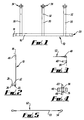
Fig 1 is a diagrammatic front view of a first mounting assembly according to the invention; -
Fig 2 is a diagrammatic side view of the assembly offig 1 ; -
Fig 3 is a diagrammatic plan view of part of the assembly offig 1 ; -
Fig 4 is a diagrammatic front view of a further part of the assembly offig 1 ; -
Fig 5 is a side view of a component of the assembly offig 1 ; -
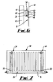
Fig 6 is a more detailed side view of an upper part of the assembly offig 1 in use; -
Fig 7 is a diagrammatic front view of a second mounting assembly according to the invention in use; -
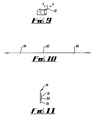
Fig 8 is a diagrammatic exploded front view of a third mounting assembly according to the invention; -
Fig 9 is a diagrammatic front view of a part of the assembly offig 8 ; -
Fig 10 is a diagrammatic plan view of a further part of the assembly offig 8 ; and -
Fig 11 is a diagrammatic end view of a further part of the assembly offig 8 . -
Figs 1 to 6 show afirst mounting assembly 10 for mounting aradiator 12 against awall 14, so as to permit the upper end of theradiator 12 to be selectively pivoted forwards when required, for instance during cleaning or decorating. - The
assembly 10 includes an elongate transverse support part in the form of a strip mountable substantially flush against a wall to extend horizontally thereacross. A plurality ofholes 18 may be provided as required through thestrip 16 to permit mounting on the wall. - A support member in the form of a
bracket 20 is provided at each end of thestrip 16. Eachbracket 20 extends horizontally outwardly from thestrip 16. Eachbracket 20 includes afirst spacer part 22 and a second shapedpart 24 which defines a substantially arcuate upwardlyopen recess 26. Thebracket 20 can support any of an end of thecentral heating radiator 12, a connection to the central heating radiator, or a pipe connected to the end of acentral heating radiator 12. - Three longitudinal support parts in the form of
strips 30 of metal extending upwardly from thehorizontal strip 16 are provided.Holes 32 are provided through thestrips 30 to permit mounting thereof flush against awall 14. Any required pattern ofholes 32 may be provided as appropriate. - An
engagement assembly 34 is provided at the upper end of eachstrip 30. Eachassembly 34 includes anengagement member 36 slidably movable in a vertically extendingchannel 38. The upper end of theengagement member 36 includes a horizontally extendingfinger 40 with a downwardly and outwardly pointingend 42, which end is selectively engageable with abracket 44 on the back of theradiator 12 towards the top thereof, as is shown infig 6 . A smaller outwardly extendingfinger 46 is provided at the lower end of theengagement member 36 to prevent themember 36 being pulled out of thechannel 38. - A
hook member 48 is provided on a side end of eachengagement assembly 34, and eachmember 48 defines an upwardlyopen recess 50. Aretention member 52 in the form of a length ofwire 53 withloops 54 at each end is engageable oneloop 54 with thehook member 48 and theother loop 54 with a further hook member (not shown) on theradiator 12 adjacent thebracket 44. In normal usage thetension member 52 would extend between these two hook members, but theretention member 52 can be unhooked from either of these members if required. -
Fig 7 shows a similarsecond mounting assembly 56 mounting asmaller radiator 58 on a wall. As theradiator 58 is smaller than theradiator 12, it is only necessary to provide two spacedvertical strips 30 extending from thestrip 16, eachstrip 30 with arespective engagement assembly 34. - In use, the
assemblies assemblies holes strip 16 is extending substantially horizontally. - A radiator can then be located in place with the radiator being supported by the
brackets 20. Thebrackets 20 will engage with any of an end of theradiator other radiators radiator engagement members 36 slid into position to engage with thebrackets 44. - To gain access behind the
radiators engagement members 36 are slid upwardly, and theradiator retention member 52 extending between thehook members 48 on the radiator andengagement assembly 34 prevent aradiator radiator retention member 52 can readily be unhooked from one or both of the hook members. -
Figs 8 to 11 show a furthersimilar mounting assembly 60, with theassembly 60 being illustrated in a disassembled condition. Theassembly 60 includes an elongatetransverse support part 62, and two discretelongitudinal support parts 64. Twochannels 66 are defined by respective raised portions in thetransverse support part 62 as is best seen inFig 10 . In an assembled condition, a narrowlower end portion 68 of eachlongitudinal support part 64 locates in a respective one of thechannels 66. Anengagement assembly 70 is provided at the upper end of eachlongitudinal support part 64. - Each
engagement assembly 70 includes anengagement member 72 slidably moveable in a horizontal direction indicated by the arrows X in a horizontally extending channel. Theengagement member 72 is selectively engageable with a bracket on the back of theradiator 12. - A
bracket 74 is provided for each end of thetransverse support part 62. Eachbracket 74 includes a shallown shape member 76 extending from amounting plate 78, to define achannel 80 therebetween. Each end of thesupport part 62 is welded in a respective one of thechannels 80. Abracket member 20 can also be slid into eachchannel 80, as is shown by the arrows Y. Mountingholes 82 are provided through thesupport parts plate 78 to permit mounting of theassembly 60 to a wall. - The
assembly 60 can thus be readily disassembled to permit compact packaging, and then assembled in location when required. - There are thus described mounting assemblies for a radiator which readily permit the radiator to be pivoted forwards as required. The arrangement of the horizontal strip with the vertical strips extending therefrom renders it a very straightforward task to fix assemblies according to the invention to a wall in a required position and to a correct alignment. Otherwise, with separate unconnected components it can be relatively difficult and time consuming to mount such an assembly with the different components in a correct relative position and alignment. With the present invention, radiators and mounting assemblies can readily be supplied together such that a mounting assembly of a correct size and configuration is provided for the radiator.
- Various other modifications may be made without departing from the scope of the invention. For instance the parts of the assembly mountable to the wall may take a different form, shape or size dependant on the radiator to be mounted. The engagement part may take a different form. It may not be necessary to provide a retention member, or this may take a different form. The engagement part could be movable other than by sliding.
- Whilst endeavouring in the foregoing specification to draw attention to those features of the invention believed to be of particular importance it should be understood that the Applicant claims protection in respect of any patentable feature or combination of features hereinbefore referred to and/or shown in the drawings whether or not particular emphasis has been placed thereon.
Claims (14)
- A mounting assembly (10), the assembly including an elongate transverse support part (16, 62) mountable to a wall to extend substantially horizontally thereacross, a pair of support members (20, 74) provided on the transverse support part spaced from each other, each support member including a bracket member (20) extending outwardly from the transverse support part and defining an arcuate upwardly open recess (26), which recess can supportingly rotatably receive any of an end of a central heating radiator(12, 58), a connection to a central heating radiator, or a pipe connected to the end of a central heating radiator, the assembly also including at least two spaced elongate longitudinal support parts (30, 64), each support part extending from the transverse support part (16, 62), and being mountable to a wall to extend at least generally vertically upwards from the transverse support part, an engagement part (34, 70) being provided towards the upper end of each longitudinal support part (30, 64), each engagement part (34, 70) being selectively engageable with a central heating radiator (12, 58) towards an upper part thereof, which radiator is supported by the bracket members (20), to retain the radiator (12, 58) in position adjacent the wall.
- A mounting assembly according to claim 1, characterised in that the engagement part includes an engagement member (36, 72) movable relative to the respective longitudinal support part, to be movable between a position engaging a radiator, and a position clear of the radiator to permit pivoting thereof.
- A mounting assembly according to claim 2, characterised in that the engagement member (36, 72) is slidably movable relative to the respective longitudinal support part.
- A mounting assembly according to any of the preceding claims, characterised in that the engagement part (34, 70) also includes a retention member (52) extendable between a location towards the upper end of one of the longitudinal support parts (30, 64), and a location towards an upper part of a central heating radiator (12, 58) to prevent pivoting of the radiator outwardly from a wall beyond a predetermined amount.
- A mounting assembly according to claim 4, characterised in that the retention member is in the form of a line means (53).
- A mounting assembly according to claims 4 or 5, characterised in that the retention member (53) is selectively mountable to the longitudinal support part and/or the radiator, to enable selective unlimited pivoting of the radiator.
- A mounting assembly according to any of the preceding claims, characterised in that the transverse support part (16, 62) and/or longitudinal support parts (30, 64) are formed of strips of material which are mountable substantially flush against a wall.
- A mounting assembly according to any of the preceding claims, in which the longitudinal support parts (30, 64) extend substantially perpendicularly relative to the transverse support parts (16, 62).
- A mounting assembly according to any of the preceding claims, characterised in that two longitudinal support parts are provided.
- A mounting assembly according to any of claims 1 to 8, characterised in that three longitudinal support parts are provided.
- A mounting assembly according to any of the preceding claims, characterised in that a lower end of each longitudinal support part is locatable in a channel (66) defined by the elongate transverse support part.
- A mounting assembly according to any of the preceding claims characterised in that the assembly includes a pair of mounting brackets (74), with each bracket defining a channel (80) with part of each of the bracket members locatable in the channel defined by a respective one of the mounting brackets.
- A mounting assembly according to claim 12, characterised in that ends of the transverse support part 62 are locatable in the channel (80) defined by a respective one of the mounting brackets (74).
- A central heating radiator assembly, the assembly including a radiator and a mounting assembly according to any of the preceding claims, with the mounting assembly being dimensioned to mount the radiator to a wall, with the bracket members receiving any of an end of the radiator, a connection to the radiator, or a pipe connected to the end of the radiator.
Applications Claiming Priority (1)
| Application Number | Priority Date | Filing Date | Title |
|---|---|---|---|
| GB0804321A GB2458163A (en) | 2008-03-08 | 2008-03-08 | Central heating radiator mounting assembly |
Publications (1)
| Publication Number | Publication Date |
|---|---|
| EP2098792A1 true EP2098792A1 (en) | 2009-09-09 |
Family
ID=39327755
Family Applications (1)
| Application Number | Title | Priority Date | Filing Date |
|---|---|---|---|
| EP09250637A Withdrawn EP2098792A1 (en) | 2008-03-08 | 2009-03-05 | Mounting assembly |
Country Status (2)
| Country | Link |
|---|---|
| EP (1) | EP2098792A1 (en) |
| GB (1) | GB2458163A (en) |
Cited By (2)
| Publication number | Priority date | Publication date | Assignee | Title |
|---|---|---|---|---|
| WO2014013321A1 (en) * | 2012-07-18 | 2014-01-23 | Zehnder Verkaufs- Und Verwaltungs Ag | System for fixing a radiator to a wall |
| CN109442545A (en) * | 2018-11-05 | 2019-03-08 | 杨佳魏 | A kind of carbon fibre pipe heater |
Citations (6)
| Publication number | Priority date | Publication date | Assignee | Title |
|---|---|---|---|---|
| BE837585A (en) * | 1976-01-15 | 1976-05-03 | RAIL-SHAPED PRINTED ELEMENTS | |
| GB2308882A (en) * | 1995-12-19 | 1997-07-09 | William Mason | Freefall central heating radiator system |
| FR2768801A1 (en) * | 1997-09-23 | 1999-03-26 | Atlantic Industrie Sas | Wall mounting for heater |
| EP1010950A1 (en) * | 1998-11-20 | 2000-06-21 | Turad B.V. | Device for fixing a heating radiator |
| NL1022997C2 (en) * | 2003-03-21 | 2004-09-22 | Holsteijn & Kemna Special Prod | Combination of wall mounting device and radiator, includes radiator tilt compensation device, preferably spring |
| GB2404165A (en) * | 2003-07-25 | 2005-01-26 | James Edwards | Template for hanging a radiator |
Family Cites Families (5)
| Publication number | Priority date | Publication date | Assignee | Title |
|---|---|---|---|---|
| GB2096451B (en) * | 1981-03-26 | 1985-07-03 | Hara William Francis O | Radiator supporting device |
| GB2148097A (en) * | 1983-10-21 | 1985-05-30 | John Charles Wells | Radiator securing means |
| GB2254412B (en) * | 1991-03-23 | 1995-10-11 | Trevor William Wilson | Pivotal wall mounting for a radiator |
| GB9818066D0 (en) * | 1998-08-20 | 1998-10-14 | Keeling Malcolm | Mounting assembly |
| GB2412951B (en) * | 2004-04-07 | 2008-04-23 | Malcolm Keeling | Mounting assembly |
-
2008
- 2008-03-08 GB GB0804321A patent/GB2458163A/en not_active Withdrawn
-
2009
- 2009-03-05 EP EP09250637A patent/EP2098792A1/en not_active Withdrawn
Patent Citations (6)
| Publication number | Priority date | Publication date | Assignee | Title |
|---|---|---|---|---|
| BE837585A (en) * | 1976-01-15 | 1976-05-03 | RAIL-SHAPED PRINTED ELEMENTS | |
| GB2308882A (en) * | 1995-12-19 | 1997-07-09 | William Mason | Freefall central heating radiator system |
| FR2768801A1 (en) * | 1997-09-23 | 1999-03-26 | Atlantic Industrie Sas | Wall mounting for heater |
| EP1010950A1 (en) * | 1998-11-20 | 2000-06-21 | Turad B.V. | Device for fixing a heating radiator |
| NL1022997C2 (en) * | 2003-03-21 | 2004-09-22 | Holsteijn & Kemna Special Prod | Combination of wall mounting device and radiator, includes radiator tilt compensation device, preferably spring |
| GB2404165A (en) * | 2003-07-25 | 2005-01-26 | James Edwards | Template for hanging a radiator |
Cited By (5)
| Publication number | Priority date | Publication date | Assignee | Title |
|---|---|---|---|---|
| WO2014013321A1 (en) * | 2012-07-18 | 2014-01-23 | Zehnder Verkaufs- Und Verwaltungs Ag | System for fixing a radiator to a wall |
| EP2947394A1 (en) * | 2012-07-18 | 2015-11-25 | Zehnder Group International AG | System for fixing a heating radiator to a wall |
| EP3336441A1 (en) * | 2012-07-18 | 2018-06-20 | Zehnder Group International AG | System for fixing a heating radiator to a wall |
| CN109442545A (en) * | 2018-11-05 | 2019-03-08 | 杨佳魏 | A kind of carbon fibre pipe heater |
| CN109442545B (en) * | 2018-11-05 | 2020-12-04 | 湖南惠康电器有限公司 | Carbon fiber tube warmer |
Also Published As
| Publication number | Publication date |
|---|---|
| GB2458163A (en) | 2009-09-09 |
| GB0804321D0 (en) | 2008-04-16 |
Similar Documents
| Publication | Publication Date | Title |
|---|---|---|
| US8602019B2 (en) | Retractable oven rack assembly | |
| US11503935B2 (en) | Adjustable over-the-door hooks and racks | |
| US6758355B2 (en) | Display rack with repositionable shelf | |
| US20090211997A1 (en) | Shelving system with removable shelves | |
| EP1443292A3 (en) | Refrigerator compartment housing vertically adjustable shelves | |
| WO2002005682A2 (en) | Wire basket system | |
| US20070221597A1 (en) | Supporting bracket for wall-mount rack | |
| US20140197121A1 (en) | Width-adjustable storage module for cabinets | |
| WO2004056236B1 (en) | Adjustable closet organizer system | |
| EP1892477A3 (en) | Baking stone rack | |
| US8820314B1 (en) | Extendible oven rack apparatus | |
| US6341754B1 (en) | Small appliance modular hanger system | |
| EP2098792A1 (en) | Mounting assembly | |
| EP1894788A1 (en) | Device for attaching an electronic device to a support | |
| JP6496313B2 (en) | Sliding door guide device and method for attaching a sliding door | |
| CA2620206A1 (en) | Tank retainer | |
| US7926214B2 (en) | Two-way adjustable sign system | |
| WO2005046401A1 (en) | Sliding type merchandise display shelf | |
| EP1585409A1 (en) | Display system | |
| CN214465388U (en) | Connecting structure of support rod and support | |
| KR101289355B1 (en) | Fixing system for hanging bar for kitchen utensils | |
| CN213981517U (en) | Novel connecting structure | |
| JP3551399B2 (en) | Shelf partitioning equipment | |
| JPH0335169Y2 (en) | ||
| CN206324628U (en) | A kind of food materials of cooking equipment pick and place structure |
Legal Events
| Date | Code | Title | Description |
|---|---|---|---|
| PUAI | Public reference made under article 153(3) epc to a published international application that has entered the european phase |
Free format text: ORIGINAL CODE: 0009012 |
|
| AK | Designated contracting states |
Kind code of ref document: A1 Designated state(s): AT BE BG CH CY CZ DE DK EE ES FI FR GB GR HR HU IE IS IT LI LT LU LV MC MK MT NL NO PL PT RO SE SI SK TR |
|
| AX | Request for extension of the european patent |
Extension state: AL BA RS |
|
| AKX | Designation fees paid | ||
| REG | Reference to a national code |
Ref country code: DE Ref legal event code: 8566 |
|
| STAA | Information on the status of an ep patent application or granted ep patent |
Free format text: STATUS: THE APPLICATION IS DEEMED TO BE WITHDRAWN |
|
| 18D | Application deemed to be withdrawn |
Effective date: 20100310 |