EP2098705B1 - Control device for variable valve mechanism - Google Patents
Control device for variable valve mechanism Download PDFInfo
- Publication number
- EP2098705B1 EP2098705B1 EP07860120A EP07860120A EP2098705B1 EP 2098705 B1 EP2098705 B1 EP 2098705B1 EP 07860120 A EP07860120 A EP 07860120A EP 07860120 A EP07860120 A EP 07860120A EP 2098705 B1 EP2098705 B1 EP 2098705B1
- Authority
- EP
- European Patent Office
- Prior art keywords
- value
- control device
- counter value
- motor
- engine
- Prior art date
- Legal status (The legal status is an assumption and is not a legal conclusion. Google has not performed a legal analysis and makes no representation as to the accuracy of the status listed.)
- Not-in-force
Links
- 238000001514 detection method Methods 0.000 claims description 73
- 238000012937 correction Methods 0.000 claims description 25
- 238000004891 communication Methods 0.000 claims description 19
- 238000002485 combustion reaction Methods 0.000 claims description 10
- 230000001174 ascending effect Effects 0.000 claims description 2
- 238000000034 method Methods 0.000 description 91
- 238000006073 displacement reaction Methods 0.000 description 35
- 230000005405 multipole Effects 0.000 description 5
- 230000003287 optical effect Effects 0.000 description 3
- 238000006243 chemical reaction Methods 0.000 description 2
- 230000007423 decrease Effects 0.000 description 2
- 239000000446 fuel Substances 0.000 description 2
- 230000005540 biological transmission Effects 0.000 description 1
- 125000004122 cyclic group Chemical group 0.000 description 1
- 230000001419 dependent effect Effects 0.000 description 1
- 230000000994 depressogenic effect Effects 0.000 description 1
- 238000010586 diagram Methods 0.000 description 1
- 238000005259 measurement Methods 0.000 description 1
- 238000012986 modification Methods 0.000 description 1
- 230000004048 modification Effects 0.000 description 1
- 230000000630 rising effect Effects 0.000 description 1
Images


Classifications
-
- F—MECHANICAL ENGINEERING; LIGHTING; HEATING; WEAPONS; BLASTING
- F01—MACHINES OR ENGINES IN GENERAL; ENGINE PLANTS IN GENERAL; STEAM ENGINES
- F01L—CYCLICALLY OPERATING VALVES FOR MACHINES OR ENGINES
- F01L13/00—Modifications of valve-gear to facilitate reversing, braking, starting, changing compression ratio, or other specific operations
- F01L13/0015—Modifications of valve-gear to facilitate reversing, braking, starting, changing compression ratio, or other specific operations for optimising engine performances by modifying valve lift according to various working parameters, e.g. rotational speed, load, torque
- F01L13/0063—Modifications of valve-gear to facilitate reversing, braking, starting, changing compression ratio, or other specific operations for optimising engine performances by modifying valve lift according to various working parameters, e.g. rotational speed, load, torque by modification of cam contact point by displacing an intermediate lever or wedge-shaped intermediate element, e.g. Tourtelot
-
- F—MECHANICAL ENGINEERING; LIGHTING; HEATING; WEAPONS; BLASTING
- F01—MACHINES OR ENGINES IN GENERAL; ENGINE PLANTS IN GENERAL; STEAM ENGINES
- F01L—CYCLICALLY OPERATING VALVES FOR MACHINES OR ENGINES
- F01L13/00—Modifications of valve-gear to facilitate reversing, braking, starting, changing compression ratio, or other specific operations
- F01L13/0015—Modifications of valve-gear to facilitate reversing, braking, starting, changing compression ratio, or other specific operations for optimising engine performances by modifying valve lift according to various working parameters, e.g. rotational speed, load, torque
-
- F—MECHANICAL ENGINEERING; LIGHTING; HEATING; WEAPONS; BLASTING
- F02—COMBUSTION ENGINES; HOT-GAS OR COMBUSTION-PRODUCT ENGINE PLANTS
- F02D—CONTROLLING COMBUSTION ENGINES
- F02D13/00—Controlling the engine output power by varying inlet or exhaust valve operating characteristics, e.g. timing
- F02D13/02—Controlling the engine output power by varying inlet or exhaust valve operating characteristics, e.g. timing during engine operation
-
- F—MECHANICAL ENGINEERING; LIGHTING; HEATING; WEAPONS; BLASTING
- F02—COMBUSTION ENGINES; HOT-GAS OR COMBUSTION-PRODUCT ENGINE PLANTS
- F02D—CONTROLLING COMBUSTION ENGINES
- F02D41/00—Electrical control of supply of combustible mixture or its constituents
- F02D41/22—Safety or indicating devices for abnormal conditions
- F02D41/222—Safety or indicating devices for abnormal conditions relating to the failure of sensors or parameter detection devices
-
- F—MECHANICAL ENGINEERING; LIGHTING; HEATING; WEAPONS; BLASTING
- F01—MACHINES OR ENGINES IN GENERAL; ENGINE PLANTS IN GENERAL; STEAM ENGINES
- F01L—CYCLICALLY OPERATING VALVES FOR MACHINES OR ENGINES
- F01L1/00—Valve-gear or valve arrangements, e.g. lift-valve gear
- F01L1/12—Transmitting gear between valve drive and valve
- F01L1/18—Rocking arms or levers
- F01L1/185—Overhead end-pivot rocking arms
-
- F—MECHANICAL ENGINEERING; LIGHTING; HEATING; WEAPONS; BLASTING
- F01—MACHINES OR ENGINES IN GENERAL; ENGINE PLANTS IN GENERAL; STEAM ENGINES
- F01L—CYCLICALLY OPERATING VALVES FOR MACHINES OR ENGINES
- F01L1/00—Valve-gear or valve arrangements, e.g. lift-valve gear
- F01L1/20—Adjusting or compensating clearance
- F01L1/22—Adjusting or compensating clearance automatically, e.g. mechanically
- F01L1/24—Adjusting or compensating clearance automatically, e.g. mechanically by fluid means, e.g. hydraulically
- F01L1/2405—Adjusting or compensating clearance automatically, e.g. mechanically by fluid means, e.g. hydraulically by means of a hydraulic adjusting device located between the cylinder head and rocker arm
-
- F—MECHANICAL ENGINEERING; LIGHTING; HEATING; WEAPONS; BLASTING
- F01—MACHINES OR ENGINES IN GENERAL; ENGINE PLANTS IN GENERAL; STEAM ENGINES
- F01L—CYCLICALLY OPERATING VALVES FOR MACHINES OR ENGINES
- F01L1/00—Valve-gear or valve arrangements, e.g. lift-valve gear
- F01L1/02—Valve drive
- F01L1/04—Valve drive by means of cams, camshafts, cam discs, eccentrics or the like
- F01L1/047—Camshafts
- F01L1/053—Camshafts overhead type
- F01L2001/0537—Double overhead camshafts [DOHC]
-
- F—MECHANICAL ENGINEERING; LIGHTING; HEATING; WEAPONS; BLASTING
- F01—MACHINES OR ENGINES IN GENERAL; ENGINE PLANTS IN GENERAL; STEAM ENGINES
- F01L—CYCLICALLY OPERATING VALVES FOR MACHINES OR ENGINES
- F01L2305/00—Valve arrangements comprising rollers
-
- F—MECHANICAL ENGINEERING; LIGHTING; HEATING; WEAPONS; BLASTING
- F01—MACHINES OR ENGINES IN GENERAL; ENGINE PLANTS IN GENERAL; STEAM ENGINES
- F01L—CYCLICALLY OPERATING VALVES FOR MACHINES OR ENGINES
- F01L2800/00—Methods of operation using a variable valve timing mechanism
-
- F—MECHANICAL ENGINEERING; LIGHTING; HEATING; WEAPONS; BLASTING
- F01—MACHINES OR ENGINES IN GENERAL; ENGINE PLANTS IN GENERAL; STEAM ENGINES
- F01L—CYCLICALLY OPERATING VALVES FOR MACHINES OR ENGINES
- F01L2800/00—Methods of operation using a variable valve timing mechanism
- F01L2800/01—Starting
-
- F—MECHANICAL ENGINEERING; LIGHTING; HEATING; WEAPONS; BLASTING
- F01—MACHINES OR ENGINES IN GENERAL; ENGINE PLANTS IN GENERAL; STEAM ENGINES
- F01L—CYCLICALLY OPERATING VALVES FOR MACHINES OR ENGINES
- F01L2800/00—Methods of operation using a variable valve timing mechanism
- F01L2800/03—Stopping; Stalling
-
- F—MECHANICAL ENGINEERING; LIGHTING; HEATING; WEAPONS; BLASTING
- F01—MACHINES OR ENGINES IN GENERAL; ENGINE PLANTS IN GENERAL; STEAM ENGINES
- F01L—CYCLICALLY OPERATING VALVES FOR MACHINES OR ENGINES
- F01L2820/00—Details on specific features characterising valve gear arrangements
- F01L2820/03—Auxiliary actuators
- F01L2820/032—Electric motors
-
- F—MECHANICAL ENGINEERING; LIGHTING; HEATING; WEAPONS; BLASTING
- F01—MACHINES OR ENGINES IN GENERAL; ENGINE PLANTS IN GENERAL; STEAM ENGINES
- F01L—CYCLICALLY OPERATING VALVES FOR MACHINES OR ENGINES
- F01L2820/00—Details on specific features characterising valve gear arrangements
- F01L2820/04—Sensors
- F01L2820/042—Crankshafts position
-
- Y—GENERAL TAGGING OF NEW TECHNOLOGICAL DEVELOPMENTS; GENERAL TAGGING OF CROSS-SECTIONAL TECHNOLOGIES SPANNING OVER SEVERAL SECTIONS OF THE IPC; TECHNICAL SUBJECTS COVERED BY FORMER USPC CROSS-REFERENCE ART COLLECTIONS [XRACs] AND DIGESTS
- Y02—TECHNOLOGIES OR APPLICATIONS FOR MITIGATION OR ADAPTATION AGAINST CLIMATE CHANGE
- Y02T—CLIMATE CHANGE MITIGATION TECHNOLOGIES RELATED TO TRANSPORTATION
- Y02T10/00—Road transport of goods or passengers
- Y02T10/10—Internal combustion engine [ICE] based vehicles
- Y02T10/12—Improving ICE efficiencies
-
- Y—GENERAL TAGGING OF NEW TECHNOLOGICAL DEVELOPMENTS; GENERAL TAGGING OF CROSS-SECTIONAL TECHNOLOGIES SPANNING OVER SEVERAL SECTIONS OF THE IPC; TECHNICAL SUBJECTS COVERED BY FORMER USPC CROSS-REFERENCE ART COLLECTIONS [XRACs] AND DIGESTS
- Y02—TECHNOLOGIES OR APPLICATIONS FOR MITIGATION OR ADAPTATION AGAINST CLIMATE CHANGE
- Y02T—CLIMATE CHANGE MITIGATION TECHNOLOGIES RELATED TO TRANSPORTATION
- Y02T10/00—Road transport of goods or passengers
- Y02T10/10—Internal combustion engine [ICE] based vehicles
- Y02T10/40—Engine management systems
Definitions
- the present invention relates to a control device of a variable valve mechanism that varies valve actuation parameters of an internal combustion engine.
- the internal combustion engine may include a variable valve mechanism that varies actuation parameters of engine valves such as intake valves or exhaust valves.
- the variable valve mechanism is driven by, for example, a motor rotating in a set angular range.
- current values representing the valve actuation parameters correspond to the motor rotational angle. Accordingly, in order to accurately control the valve actuation parameters, it is important to accurately detect and control the motor rotational angle.
- Patent Document 1 discloses a motor rotational angle detection device.
- a position sensor which is, for example, an encoder, detects a pulse signal when a motor rotates.
- a position counter counts the pulse signal and obtains a counter value. The motor rotational angle is detected based on the counter value.
- the motor rotational angle detection device when not powered, cannot detect a change in the actual motor rotational angle. However, the actual motor rotational angle may change even when the motor rotational angle detection device is not powered.
- a control device of a variable valve mechanism as defined in claim 1.
- Figs. 1 to 11 show one embodiment of the present invention.
- the embodiment relates to a control device of a variable valve mechanism 14.
- the control device includes a motor control device 50 and an engine control device 51.
- Fig. 1 is the cross-sectional view showing the structure of the vicinity of a cylinder head 2 of an engine 1.
- the cylinder head 2, the cylinder block 3, and the piston 5 define a combustion chamber 6.
- An intake passage 7 and an exhaust passage 8 are connected to the combustion chamber 6. Communication between the intake passage 7 and the combustion chamber 6 is selectively permitted and blocked by an intake valve 9, which selectively opens and closes. Communication between the exhaust passage 8 and the combustion chamber 6 is selectively permitted and blocked by an exhaust valve 10, which selectively opens and closes.
- An intake camshaft 11 driving the intake valve 9 and an exhaust camshaft 12 driving the exhaust valve 10 are arranged on the cylinder head 2.
- the intake camshaft 11 and the exhaust camshaft 12 are rotated through transmission of rotation of the crankshaft of the engine 1 to the camshafts 11, 12.
- the intake camshaft 11 and the exhaust camshaft 12 include an intake cam 11a and an exhaust cam 12a, respectively.
- the intake cam 11a and the intake camshaft 11 rotate integrally to selectively open and close the intake valve 9.
- the exhaust cam 12a and the exhaust camshaft 12 rotate integrally to selectively open and close the exhaust valve 10.
- the engine 1 has a variable valve mechanism 14 arranged between the intake cam 11a and the intake valve 9.
- the variable valve mechanism 14 varies the maximum lift amount of the intake valve 9 and the duration angle of the intake cam 11a.
- the maximum lift amount of the intake valve 9 and the duration angle of the intake cam 11a represent the valve actuation parameters of the intake valve 9.
- the variable valve mechanism 14 is controlled in such a manner that, as the necessary intake air amount increases, the maximum lift amount and the duration angle increase. That is, the variable valve mechanism 14 varies valve actuation parameters of engine valves including the intake valve 9 and the exhaust valve 10.
- the variable valve mechanism 14 has a locker shaft 15, a control shaft 16, an input arm 17, and an output arm 18.
- the locker shaft 15 is fixed to the cylinder head 2 and shaped as a pipe extending parallel with the intake camshaft 11.
- the control shaft 16 is shaped like a bar and passed through the locker shaft 15.
- the input arm 17 swings about the axis of the control shaft 16.
- the output arm 18 swings about the axis in correspondence with swinging of the input arm 17.
- a roller 19 is rotatably attached to the input arm 17.
- a coil spring 20 presses the roller 19 against the intake cam 11a.
- the output arm 18 is pressed against the locker arm 21 when swinging, thus lifting the intake valve 9 through the locker arm 21.
- a first end of the locker arm 21 is supported by a lash adjuster 22 and a second end of the locker arm 21 contacts the intake valve 9.
- the locker arm 21 is urged toward the output arm 18 by the valve spring 24 of the intake valve 9.
- the roller 23 is pressed against the output arm 18.
- the valve spring 24 urges the intake valve 9.
- the roller 23 is rotatably supported between the first end and the second end of the locker arm 21. Accordingly, when the input arm 17 and the output arm 18 are caused to swing by rotation of the intake cam 11a, the output arm 18 lifts the intake valve 9 through the locker arm 21, thus selectively opening and closing the intake valve 9.
- the control shaft 16 of the variable valve mechanism 14 moves axially in such a manner as to change the position of the control shaft 16 relative to the swinging direction of the input arm 17 and that of the output arm 18.
- This varies the maximum lift angle of the intake valve 9 and the duration angle of the intake cam 11a with respect to the intake valve 9.
- the maximum lift amount of the intake valve 9 and the duration angle of the intake cam 11a both decrease.
- the maximum lift amount of the intake valve 9 and the duration angle of the intake cam 11a both increase.
- variable valve mechanism 14 includes a brushless motor 47, which axially moves the control shaft 16.
- the motor control device 50 controls the brushless motor 47.
- the motor control device 50 is connected to the engine control device 51 through a communication cable 60 in such a manner that mutual communication is allowed between the motor control device 50 and the engine control device 51.
- the engine control device 51 controls the engine 1 in various manners.
- the brushless motor 47 is connected to a basal end 16a of the control shaft 16 through a conversion mechanism 48.
- the conversion mechanism 48 converts rotation of the brushless motor 47 into axial linear movement of the control shaft 16.
- the control shaft 16 moves axially and the variable valve mechanism 14 is actuated.
- the set angular range of the brushless motor 47 is set to, for example, a range corresponding to ten revolutions of the brushless motor 47, or 0° to 3600°.
- the control shaft 16 moves away from the brushless motor 47. This changes the position of the input arm 17 and the position of the output arm 18 relative to each other with respect to the swinging directions in such a manner that the input arm 17 and the output arm 18 are brought closer to each other.
- the control shaft 16 moves toward the brushless motor 47, thus changing the position of the input arm 17 and the position of the output arm 18 relative to each other with respect to the swinging directions in such a manner that the input arm 17 and the output arm 18 separate from each other.
- Rotation of the brushless motor 47 changes the position of the input arm 17 and the position of the output arm 18 relative to each other with respect to the swinging directions. This varies the maximum lift amount of the intake valve 9 and the duration angle of the intake cam 11a.
- the stator of the brushless motor 47 has a first electric angle sensor S1, a second electric angle sensor S2, a third electric angle sensor S3, a first position sensor S4, and a second position sensor S5.
- the rotor of the brushless motor 47 has a multipole magnet including four poles and a multipole magnet having 48 poles, in such a manner that the multipole magnets rotate integrally.
- the first to third electric angle sensors S1 to S3 When the brushless motor 47 rotates, the first to third electric angle sensors S1 to S3 output pulse signals the phases of which are offset from one another as illustrated in Figs. 3(a) to 3(c) in correspondence with the magnetic force of the four-pole magnet.
- the circumferential positions of the first to third electric angle sensors S1 to S3 are determined in such a manner as to obtain such pulse signals.
- the edge of the pulse signal output by each one of the first to third electric angle sensors S1 to S3 is generated whenever the brushless motor 47 rotates by 45°.
- the phase of the pulse signal of the first electric angle sensor S1 proceeds from the phase of the pulse signal of the second electric angle sensor S2 by the amount corresponding to rotation of 30° of the brushless motor 47.
- the phase of the pulse signal of the third electric angle sensor S3 is retarded from the phase of the pulse signal of the second electric angle sensor S2 by the amount corresponding to the rotation of 30° of the brushless motor 47.
- the first and second position sensors S4, S5 When the brushless motor 47 rotates, the first and second position sensors S4, S5 output pulse signals represented in Figs. 3(d) and 3(e) in correspondence with the magnetic force of the 48-pole magnet.
- the circumferential positions of the first and second position sensors S4, S5 are determined in such a manner as to obtain the pulse signals having the illustrated waveforms.
- the edge of the pulse signal output by each one of the first and second position sensors S4, S5 is generated whenever the brushless motor 47 rotates by 7.5°.
- the phase of the pulse signal of the first position sensor S4 is offset from the phase of the pulse signal of the second position sensor S5 by the amount corresponding to the rotation of the brushless motor 47 by 3.75°.
- the angular interval between the edges of the pulse signals of the first to third electric angle sensors S1 to S3 is 15°
- the angular interval between the edges of the pulse signals of the first and second position sensors S4, S5 is 3.75°, which is shorter.
- Four edges are generated by the pulse signals of the first and second position sensors S4, S5 in a single interval of the pulse signals of the first to third electric angle sensors S1 to S3.
- the motor control device 50 is electrically connected to the first to third electric angle sensors S1 to S3, the first and second position sensors S4, S5, and the brushless motor 47.
- the motor control device 50 controls the brushless motor 47 to control the variable valve mechanism 14.
- the motor control device 50 includes a CPU, a ROM, a RAM, a nonvolatile memory 57, and an input/output port.
- the CPU performs various calculation procedures.
- the ROM stores programs and data that are necessary for control.
- the RAM temporarily stores calculation results of the CPU.
- the input/output port inputs/outputs signals with respect to the exterior.
- the motor control device 50 detects the relative rotational angle of the brushless motor 47 based on the pulse signals of the position sensors S4, S5. The motor control device then calculates the absolute rotational angle of the brushless motor 47 based on the relative rotational angle and a reference position, which has been learned in advance.
- the motor control device 50 rotates the brushless motor 47 by switching power supply among energizing phases such as the U phase, the V phase, and the W phase in correspondence with the patterns of the pulse signals of the first to third electric angle sensors S1 to S3.
- the engine control device 51 also includes a CPU, a ROM, a RAM, and an input/output port. Various signals are input from the motor control device 50 to the input port of the engine control device 51 through the communication cable 60. Further, the followings are connected to the engine control device 51:
- the engine control device 51 also includes a timer 58.
- the timer 58 measures the period in which the engine speed NE is higher than or equal to a threshold value NA.
- the ignition switch 56 When the ignition switch 56 is switched on, or the ignition is turned on, the power is supplied from a battery 70 to the motor control device 50 and the engine control device 51. This starts mutual communication between the motor control device 50 and the engine control device 51 through the communication cable 60. Also, a starting motor is activated to start operation of the engine 1.
- the ignition switch 56 When the ignition switch 56 is switched off, or the ignition is turned off, the power supply to the motor control device 50 and the engine control device 51 is blocked and the engine 1 is stopped after a prescribed procedure is completed.
- the engine control device 51 acquires the operating state of the engine 1 based on detection signals from various sensors and various signals from the motor control device 50.
- the engine control device 51 outputs a command value to the motor control device 50 in order to drive the brushless motor 47 in correspondence with the operating state of the engine 1.
- the motor control device 50 drives the brushless motor 47 based on the command value. This moves the control shaft 16 axially, thus allowing the variable valve mechanism 14 to control the valve actuation parameters of the intake valve 9.
- valve actuation parameters of the intake valve 9 correspond to the axial position of the control shaft 16, or the motor rotational angle ⁇ . Accordingly, in order to precisely control the valve actuation parameters of the intake valve 9, it is important to accurately detect the motor rotational angle ⁇ and operate the brushless motor 47 in such a manner that the motor rotational angle ⁇ represents a value corresponding to target valve actuation parameters.
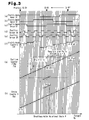
- the timing chart of Fig. 3 and the flowchart of Fig. 4 each represent a detection procedure for the motor rotational angle ⁇ of the present embodiment.
- Figs. 3(a) to 3(c) represent the pulse signals output by the first to third electric angle sensors S1 to S3 with respect to the motor rotational angle ⁇ .
- Figs. 3(d) and 3(e) represent the pulse signals output by the first and second position sensors S4, S5.
- Fig. 3(f) represents change of the electric angle counter value Ec with respect to the motor rotational angle ⁇ .
- Fig. 3(g) represents change of the position counter value Pg.
- Fig. 3(h) represents change of the stroke counter value Sg.
- the position counter P shows a detection position counter value Pk.
- the electric angle counter value Ec is a counter value of an electric angle counter E.
- the position counter value Pg is a counter value of a position counter P.
- the stroke counter value Sg is a counter value of a stroke counter S.
- the position counter value Pg represents the axial movement amount of the control shaft 16 after the ignition is turned on. In other words, the position counter value Pg represents the change of the relative rotational angle of the brushless motor 47 after the ignition is turned on.
- the stroke counter value Sg represents the axial position of the control shaft 16 with reference to the state in which the control shaft 16 is moved maximally toward the limit of movement corresponding to a distal end 16b. When the control shaft 16 is located at the limit of movement corresponding to the distal end 16b, the maximum lift amount of the intake valve 9 and the duration angle of the intake cam 11a are both minimum. That is, the stroke counter value Sg represents the motor rotational angle ⁇ with reference to the end of the set angular range of the brushless motor 47. In other words, the stroke counter value Sg represents the absolute rotational angle of the brushless motor 47.
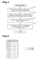
- Fig. 4 represents a counting procedure by which the electric counter value Ec, the position counter value Pg, and the stroke counter value Sg are changed.
- the motor control device 50 operates by a cycle shorter than the interval between the edges of the pulse signals of the first and second position sensors S4, S5.
- the motor control device 50 which performs the counting procedure, configures a detecting portion.
- the motor control device 50 changes the electric angle counter value Ec in step S101 as represented in Fig. 3(f) , based on the output pattern of the pulse signals of the first to third electric angle sensors S1 to S3, which are represented in Figs. 3(a) to 3(c) .
- the brushless motor 47 rotates in a reverse direction (a leftward direction as viewed in Fig. 3 ), successive integer values in the range of 0 to m are assigned to the electric angle counter value Ec in the descending order in correspondence with the output patterns of the pulse signals of the first to third electric angle sensors S1 to S3.
- the electric counter value Ec is assigned with 5 ⁇ 4 ⁇ 3 ⁇ 2 ⁇ 1 ⁇ 0 ⁇ 5 in this order.
- the brushless motor 47 is rotated in the forward direction or the reverse direction by switching the energizing phases of the brushless motor 47 based on the electric angle counter value Ec.
- step S102 the motor control device 50 selectively increases and decreases the position counter value Pg in correspondence with the output pattern of the pulse signals of the first and second position sensors S4 and S5.
- the position counter value Pg is selectively incremented and decremented by 1 in correspondence with combination of a high level H, a low level L, a rising edge ⁇ , and a falling edge ⁇ of the pulse signals of the first and second position sensors S4 and S5.
- the position counter value Pg is the count of the edges of the pulse signals of the first and second position sensors S4, S5.
- the position counter value Pg is incremented by 1 for each edge of the pulse signals of the first and second position sensors S4 and S5, which are illustrated in Figs. 3(d) and 3(e) , and proceeds rightward as viewed in Fig. 3(g) .
- the position counter value Pg is decremented by 1 for every edge and proceeds leftward as viewed in Fig. 3(g) .
- the ignition switch 56 is switched off, or the ignition is turned off, the position counter P is reset so that the counter P shows 0. Accordingly, the position counter value Pg represents the axial movement amount of the control shaft 16, or the change of the motor rotational angle ⁇ , which are caused after the ignition is turned on.
- the stroke counter value Sg represented in Fig. 3(h) is changed in correspondence with the change of the position counter value Pg represented in Fig. 3(g) .
- the motor control device 50 calculates a detection position counter value Pk by adding a correction value ⁇ P to the position counter value Pg.
- the motor control device 50 obtains the stroke counter value Sg by adding a value -Pr, which is a learned value Pr with a reversed sign, to the detection position counter value Pk.
- Pk Pg + ⁇ P
- Sg Pk - Pr.
- the correction value ⁇ P is 0.
- the learned value Pr is the detection position counter value Pk in the state in which the control shaft 16 is moved to the limit of movement corresponding to the distal end 16b of the movable range, or the motor rotational angle ⁇ is changed to the limit of movement of the set angular range.
- the learned value Pr is an initial value of the motor rotational angle ⁇ .
- the learned value Pr is learned under prescribed conditions after the ignition is turned on and stored in the nonvolatile memory 57.
- the stroke counter value Sg represents the axial position of the control shaft 16 with reference to the state in which the control shaft 16 is moved to the limit of movement corresponding to the distal end 16b.
- the stroke counter value Sg represents the motor rotational angle ⁇ with reference to the limit of movement of the set angular range of the brushless motor 47.
- the motor control device 50 detects the motor rotational angle ⁇ based on the stroke counter value Sg. To control the valve actuation parameters of the intake valve 9 by operating the variable valve mechanism 14, the motor control device 50 operates the brushless motor 47 in such a manner that the detection value ⁇ d of the motor rotational angle ⁇ becomes a value corresponding to the target valve actuation parameters commanded by the engine control device 51. As a result, the valve actuation parameters of the intake valve 9 are precisely controlled to achieve the target.
- the motor control device 50 stores the position counter value Pg in the nonvolatile memory 57 before the position counter value Pg is reset to 0 when the ignition is turned off. Then, after the ignition is turned on, the motor control device 50 reads out the position counter value Pg from the nonvolatile memory 57 and resumes counting the position counter value Pg. After the engine 1 is restarted, the stroke counter value Sg, which is set in correspondence with the position counter value Pg, corresponds to the motor rotational angle ⁇ .
- the stroke counter value Sg which is set in correspondence with the position counter value Pg, may not correspond to the motor rotational angle ⁇ .
- this problem is solved by the present embodiment.
- the motor rotational angle ⁇ may change due to mechanical looseness in the period from when the ignition is turned off to stop the engine to when the ignition is turned on to restart the engine.
- the motor rotational angle ⁇ at the time when the engine is restarted does not correspond to the position counter value Pg, which was stored when the engine was stopped. That is, the position counter value Pg, counting of which is resumed after the engine is restarted, may be displaced from the value corresponding to the motor rotational angle ⁇ .
- the position counter value Pg of 29 corresponding to the detection value ⁇ d of the motor rotational angle ⁇ does not coincide with the actual value ⁇ r of 16 of the motor rotational angle ⁇ .
- the position counter value Pg of 29 is greater than the value 16 corresponding to the actual value ⁇ r of the motor rotational angle ⁇ by the difference of 13.
- the stroke counter value Sg which is set in correspondence with the position counter value Pg, does not correspond to the actual value ⁇ r of the motor rotational angle ⁇ .
- the stroke counter value Sg may be 344, which is greater than 331, the value corresponding to the actual axial position of the control shaft 16, by the difference of 13.
- the detection value ⁇ d of the motor rotational angle ⁇ obtained in correspondence with the stroke counter value Sg of 344 does not represent the actual value ⁇ r, or is inaccurate.
- the motor control device 50 of the present embodiment operates in such a manner that the position counter value Pg at the time when the ignition is turned on corresponds to the actual value ⁇ r of the motor rotational angle ⁇ by carrying out the stop/start counting procedure.
- the stop/start counting procedure, or a stop/start position counting procedure includes the following procedures, such as a first procedure PR1, a second procedure PR2, and a third procedure PR3.
- the correction value ⁇ P in step S103 of Fig. 4 is calculated in such a manner that the detection position counter value Pk corresponds to the actual value ⁇ r of the motor rotational angle ⁇ .
- the motor control device 50 acquires the actual value ⁇ r of the motor rotational angle ⁇ , which has changed in the period from when the ignition is turned off to when the ignition is turned on.
- the motor control device 50 calculates a first counter value Eg and a second counter value Ei.
- the first counter value Eg is an electric angle counter value at the time when the ignition is turned off and the second counter value Ei is an electric angle counter value at the time when the ignition is turned on for the first time after the ignition is turned off.
- the first counter value Eg represents the electric angle counter value at the time immediately before the power supply to the motor control device 50 is stopped.
- the second counter value Ei represents the electric angle counter value at the time immediately after the power supply to the motor control device 50 is started.
- the second counter value Ei is obtained when the ignition is turned on. Specifically, the electric angle counter value Ec varies in correspondence with the output pattern of the first to third electric angle sensors S1 to S3 and is determined in correspondence with the output pattern even immediately after the ignition is turned on.
- the second counter value Ei is stored in the nonvolatile memory 57 whenever the ignition is turned on.
- the motor control device 50 calculates a change equivalent value X using the equation (1), which will be described later.
- the change equivalent value X is a change of the position counter value Pg converted from the change of the actual value ⁇ r of the motor rotational angle ⁇ that is caused in the period in which the engine is held in a stopped state.
- the motor control device 50 calculates the correction value ⁇ P.
- the correction value ⁇ P is used to correct the current position counter value Pg stored in the nonvolatile memory 57.
- the position counter value Pg is corrected using the correction value ⁇ P in such a manner that the position counter value Pg corresponds to the actual value ⁇ r of the motor rotational angle ⁇ .
- the correction value ⁇ P is the difference between the change equivalent value X and the current position counter value Pg.
- the change equivalent value X is 13
- the current position counter value Pg is 29, and the corrected position counter value Pg is 16.
- the motor control device 50 corrects the position counter value Pg when the ignition is turned on. That is, when the ignition is turned on, the correction value ⁇ P is added to the position counter value Pg, which was reset to 0 when the ignition was turned off.
- the corrected position counter value Pg is set as the detection position counter value Pk, using which the motor rotational angle ⁇ is detected.
- the detection position counter value Pk is set in step S103 of Fig. 4 .
- the detection position counter value Pk is changed by the amount corresponding to the correction value ⁇ P with respect to the position counter P at the time when the ignition has been turned on. Accordingly, the detection position counter value Pk corresponds to the actual value ⁇ r of the motor rotational angle ⁇ .
- the motor rotational angle ⁇ is accurately detected based on the stroke counter value Sg, which is set in accordance with the detection position counter value Pk.
- n represents the number of edges of a pulse signal.
- the number of edges n represents the number of the pulse signals output by the first and second position sensors S4, S5 in the interval between the edges of the pulse signals of the first to third electric angle sensors S1 to S3.
- the number of edges n 4.
- the term (Eg - Ei) ⁇ n of the equation (1) is a position counter value Pg converted from the difference between the first counter value Eg and the second counter value Ei.
- the position counter value Pg at the time when the ignition has been turned off is a value at the time when an edge occurs in the pulse signal of any one of the first to third electric angle sensors S1 to S3, that is, for example, the position counter value Pg is 28, the term (Eg - Ei) ⁇ n is employed as the change equivalent value X without being changed.
- the term (Eg - Ei) ⁇ n is displaced from the accurate change equivalent value X by the amount corresponding to the difference between the position counter value Pg and the value at the occurrence of the edge. If the position counter value Pg is 29 as in the example of Fig. 3 , the difference between the position counter value Pg and the value at the edge 28 is 1. In this case, the term (Eg - Ei) ⁇ n is displaced from the accurate change equivalent value X by the amount corresponding to the difference 1.
- Fig. 6 represents a procedure of the position counter P carried out when the ignition switch 56 is turned off or on.
- the motor control device 50 performs the stop/start counting procedure by a cycle shorter than the interval between the edges of the pulse signals of the first and second position sensors S4, S5.
- the motor control device 50 which carries out the stop/start counting procedure, configures a calculating portion.
- the motor control device 50 determines whether the current point of time is a point immediately after the ignition switch 56 has been switched off from an ON state in step S201. If positive determination is made in step S201, the nonvolatile memory 57 stores the position counter value Pg as the position counter value Pg at the time when the ignition is turned off. Step S203 is then carried out.
- step S203 the nonvolatile memory 57 stores the electric angle counter value Ec as the first counter value Eg. Then, in step S204, the motor control device 50 resets the position counter P to 0 and ends the stop/start counting procedure.
- step S201 determines whether the current point of time is a point immediately after the ignition switch 56 has been turned on from an OFF state in step S205. If the determination of step S205 is positive, the motor control device 50 calculates the change equivalent value X by performing the first procedure PR1 in step S206 and the correction value ⁇ P by carrying out the second procedure PR2 in step S207. The stop/start counting procedure is then ended.
- the flowchart of Fig. 7 represents a position counter learning procedure. Specifically, the flowchart represents a learning procedure of the learned value Pr, or an initial position learning procedure, and a procedure for removing, or subtracting, the correction value ⁇ P from the detection position counter value Pk after the learned value Pr is learned.
- the motor control device 50 performs the position counter learning procedure by a cycle shorter than the interval between the edges of the pulse signals of the first and second position sensors S4, S5.
- step S303 the motor control device 50 performs step S303 to learn the learned value Pr if learning of the learned value Pr after the ignition has been turned on is incomplete, that is, if the determination of step S301 is positive and the determination of step S302 is positive.
- the motor control device 50 carries out step 303 to learn the learned value Pr if any learned value Pr has not been written in the nonvolatile memory 57 after the ignition was turned on and conditions for learning are met.
- step S302 One of the conditions for learning in step S302 is that the engine 1 is in a fuel cut-off control. Specifically, the engine 1 being in the fuel cut-off control reduces the influence of movement of the control shaft 16, which is moved to the limit of movement, on the operating state of the engine 1. This is advantageous for learning the learned value Pr.
- step S303 the motor control device 50 moves the control shaft 16 to the limit of movement corresponding to the distal end 16b.
- the motor rotational angle ⁇ is moved to the limit of movement of the set angular range.
- step S304 the motor control device 50 determines whether the control shaft 16 has reached the limit of movement based on whether, for example, change of the position counter P is not to happen any more.
- the motor control device 50 stores the detection position counter value Pk in this state in the nonvolatile memory 57 as the learned value Pr. This completes learning of the learned value Pr.
- the learned value Pr stored in the nonvolatile memory 57 is added, with a reversed sign, to the detection position counter value Pk in step S104 of Fig. 4 .
- the sum is set as the stroke counter value Sg.
- the learned value Pr is learned when the detection position counter value Pk corresponds to the addition of the correction value ⁇ P and the counter value of the position counter P. Accordingly, when the learned value Pr, which is stored in the nonvolatile memory 57 as a learned result, is reflected in the counter value of the stroke counter S, the stroke counter value Sg reflects the correction value ⁇ P.
- the correction value ⁇ P included in the detection position counter value Pk is unnecessary. Specifically, when the correction value ⁇ P is included in the detection position counter value Pk, the stroke counter value Sg, which is set based on this count, is inappropriate. This causes inaccuracy in the detection value ⁇ d of the motor rotational angle ⁇ , which is based on the stroke counter value Sg.
- the motor control device 50 sets the correction value ⁇ P to 0 in step S306 after the learning of the learned value Pr of steps S303 to S305 is completed. As a result, the correction value ⁇ P is subtracted from the detection position counter value Pk and the above-described problem is avoided.
- the engine control device 51 When the engine 1 operates, a movable portion of the variable valve mechanism 14, such as the control shaft 16, may be displaced unexpectedly due to mechanical instability or by receiving reactive force from the valve spring 24. In this case, the actual value ⁇ r of the motor rotational angle ⁇ does not coincide with the detection value ⁇ d.
- the engine control device 51 performs a displacement determination procedure when it is highly likely that the actual value ⁇ r of the motor rotational angle ⁇ changes unexpectedly, that is, when the engine 1 is operating and the motor control device 50 is not being powered. In the displacement determination procedure, the engine control device 51 determines whether the detection value ⁇ d of the motor rotational angle ⁇ is displaced from the actual value ⁇ r.
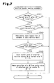
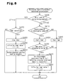
- Fig. 8 represents the flowchart of the displacement determination procedure.
- the engine control device 51 which performs this procedure cyclically, configures a determining portion.
- the engine control device 51 determines whether the motor control device 50 is being powered in step S400.
- the engine control device 51 determines whether the motor control device 50 is in a non-powered state by determining whether mutual communication between the motor control device 50 and the engine control device 51 is disabled. If the determination of step S400 is negative, that is, if the motor control device 50 is in the non-powered state, the engine control device 51 switches a communication disruption flag TF to 1 and performs step S410. If the determination of step S400 is positive, that is, if the motor control device 50 is in a powered state, the engine control device 51 switches the communication disruption flag TF to 0.
- step S410 the engine control device 51 determines whether the current engine speed NE is higher than or equal to a threshold value NA. If the determination of step S410 is positive, that is, if the engine speed NE is higher than or equal to the threshold value NA, the engine control device 51 carries out step S420 and starts the timer 58.
- step S410 determines whether the engine speed NE is less than the threshold value NA. If the determination of step S410 is negative, that is, if the engine speed NE is less than the threshold value NA, the engine control device 51 performs step S460 and stops the timer 58. Specifically, after the timer 58 is switched from the operating state to the stopped state, the timer 58 maintains the current timer value T. If the timer 58 has been held in the stopped state, the timer 58 is maintained in this state. Afterwards, the engine control device 51 suspends the displacement determination procedure.
- step S410 When positive determination is made in step S410, that is, when the engine speed NE is higher than or equal to the threshold value NA, the engine control device 51 carries out step S420 and starts the timer 58. The engine control device 51 then performs step S430. The timer 58, which has been stopped in step 460 in the previous cycle, is restarted. Counting of the timer value T is resumed from the counter value maintained in step S460. Specifically, the timer value T represents the accumulated time of the periods in which the motor control device 50 is in the non-powered state and the engine speed NE is higher than or equal to the threshold value NA.
- the engine control device 51 which performs steps S410, S420, and S460 and the timer 58 each configure a measuring portion.
- step S430 the engine control device 51 determines whether the timer value T is greater than or equal to a determination period TB.
- the determination period TB is set to a time longer than one cycle of the electric angle counter E.
- the cycle of the electric angle counter E represents one cycle of the electric angle counter value Ec, which is 0 ⁇ 1 ⁇ 2 ⁇ 3 ⁇ 4 ⁇ 5.
- the determination period TB becomes shorter as the engine speed NE becomes higher.
- the determination period TB is set in this manner since it is assumed that, when the engine 1 is operating and the motor control device 50 is in the non-powered state, likeliness that the actual value ⁇ r of the motor rotational angle ⁇ increases becomes greater as the engine speed NE becomes higher.
- step S430 If the determination of step S430 is negative, that is, if the timer value T is less than the determination period TB, the engine control device 51 suspends the displacement determination procedure.
- step S430 If the determination of step S430 is positive, that i, if the timer value T is greater than or equal to the determination period TB, the engine control device 51 performs step S440 and switches the displacement occurrence flag EF to 1. The engine control device 51 then carries out step S450, or initializes the timer value T to 0, and suspends the displacement determination procedure.
- step S440 is based on the following two facts:
- the motor control device 50 After detecting that the displacement occurrence flag EF is 1, the motor control device 50, which is in the powered state, performs the position counter learning procedure of Fig. 7 . As a result, the motor control device 50 causes the detection result ⁇ d of the motor rotational angle ⁇ to be equal to the actual value ⁇ r.
- step S400 determines whether the engine control device 51 is operating. If the determination of step S470 is negative, that is, if the timer 58 is stopped, the engine control device 51 suspends the displacement determination procedure.
- step S470 determines whether the displacement determination procedure is positive, that is, if the timer 58 is operating. If the determination of step S470 is positive, that is, if the timer 58 is operating, the engine control device 51 carries out step 480 and stops the timer 58. The engine control device 51 then performs step S490 to initialize the timer value T to 0. Then, in step S500, the engine control device 51 operates the motor control device 50 to perform the stop/start counting procedure of Fig. 6 when the motor control device 50 is switched to the powered state. Afterwards, the engine control device 51 suspends the displacement determination procedure.
- Fig. 10 represents the result of the displacement determination procedure when the engine speed NE stably increases after the engine 1 has been started.
- the power supply to the engine control device 51 and the motor control device 50 is started when the ignition is turned on.
- the communication disruption flag TF is maintained as 0.
- the determination of step S400 is negative at time point t1.
- the communication disruption flag TF is switched from 0 to 1.
- step S410 When the engine speed NE becomes higher than or equal to the threshold value NA at time point t2 after the starting motor is actuated and the engine 1 is started, positive determination is made in step S410 and the timer 58 is started in step S430.
- the timer value T continuously increases since the engine speed NE is maintained as a value higher than the threshold value NA after time point t2.
- step S430 When the timer value T reaches the determination period TB at time point t3, positive determination is caused in step S430 and the displacement occurrence flag EF is switched from 0 to 1 in step S440.
- the engine control device 51 determines that the actual value ⁇ r of the motor rotational angle ⁇ is displaced from the detection value ⁇ d.
- the motor control device 50 performs the position counter learning procedure, so that the detection value ⁇ d of the motor rotational angle ⁇ coincides with the actual value ⁇ r.
- step S4400 positive determination is made in step S4400 and then in step S470.
- step S480 the engine control device 51 initializes the timer value T to 0.
- the motor control device 50 carries out the stop/start counting procedure, and to cause the detection value ⁇ d of the motor rotational angle ⁇ to be equal to the actual value ⁇ r.
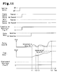
- Fig. 11 represents the result of the displacement determination procedure when the engine speed NE increases while unstably fluctuating after the engine 1 is started. Specifically, the engine speed NE repeatedly exceeds and falls short of the threshold value NA. When the engine speed NE becomes higher than or equal to the threshold value NA for the first time after the starting motor is actuated, the engine control device 51 starts the timer 58 and increases the timer value T. When the engine speed NE becomes less than the threshold value NA at time point t2, the engine control device 51 temporarily stops the timer 58. The timer 58 maintains the timer value T that has been counted immediately before stopping of the timer 58.
- the timer 58 starts operating and increases the timer value T from the maintained value.
- the timer value T reaches the determination period TB at time point t4 after operation of the timer 58 is repeatedly started and suspended, the displacement occurrence flag EF is switched from 0 to 1.
- the motor control device 50 performs the position counter learning procedure to cause the detection value ⁇ d of the motor rotational angle ⁇ to be equal to the actual value ⁇ r.
- the motor control device 50 when the motor control device 50 is switched to the powered state before time point t4 as in the case of Fig. 10 , or the motor control device 50 is switched to the powered state before the timer value T reaches the determination period TB, the timer value T is initialized. Afterwards, when the motor control device 50 is switched to the powered state, the motor control device 50 performs the stop/start counting procedure to cause the detection result ⁇ d of the motor rotational angle ⁇ to equal to the actual value ⁇ r.
- the determination period TB of the present embodiment is set to a time longer than one cycle of the electric angle counter E. Accordingly, when the second counter value Ei is a value within one cycle from the first counter value Eg, the difference between the detection value ⁇ d and the actual value ⁇ r of the motor rotational angle ⁇ is obtained appropriately through the stop/start counting procedure. When the second counter value Ei is a value exceeding the cycle from the first counter value Eg, it is determined that the detection value ⁇ d of the motor rotational angle ⁇ is displaced from the actual value ⁇ r through the displacement determination procedure. Accordingly, even if inappropriate calculation of the change equivalent value X in the stop/start counting procedure causes displacement of the detection value ⁇ d of the motor rotational angle ⁇ with respect to the actual value ⁇ r, such displacement is detected.
- the engine speed NE is measured, the engine speed NE is compared with the threshold value NA, and the period in which the engine speed NE exceeds the threshold value NA is measured generally by a relatively simple structure.
- the period in which the engine speed NE exceeds the threshold value NA is measured as the timer value T and, when the timer value T is greater than or equal to the determination period TB, it is determined that the engine 1 is operating.
- the engine control device 51 determines that the detection value ⁇ d of the motor rotational angle ⁇ is displaced from the actual value ⁇ r. Accordingly, the engine control device 51 is capable of determining whether the detection value ⁇ d of the motor rotational angle ⁇ is displaced from the actual value ⁇ r appropriately and by a simple structure.
- the present embodiment has the following advantages.
- the motor control device 50 performs the stop/start counting procedure, as represented in step 500 of Fig. 8 , when the motor control device 50 is switched from the non-powered state to the powered state. This allows the motor control device 50 to detect a change in the motor rotational angle ⁇ when the engine 1 is maintained in the stopped state.
- the motor rotational angle ⁇ that changes in the period from when the engine has been started to when the power supply to the motor control device 50 is started is calculated based on the first counter value Eg and the second counter value Ei. Accordingly, even if the power supply to the motor control device 50 is temporarily suspended while the engine 1 is being started, the motor rotational angle ⁇ that changes in the period from when the power supply to the motor control device 50 has been blocked to when such power supply is resumed is obtained when the motor control device 50 is switched to the powered state later.
- the stop/start counting procedure As a result, the following problem is solved by the stop/start counting procedure. Specifically, when the engine 1 starts, a drop in the battery voltage or temporary disconnection of the power cable feeding the motor control device 50 may cause the non-powered state of the motor control device 50, which detects the counter value of the position counter P. When in the non-powered state, the motor control device 50 cannot calculate the position counter value Pg. Accordingly, if the actual value ⁇ r of the motor rotational angle ⁇ changes when the motor control device 50 is held in the non-powered state, the change of the motor rotational angle ⁇ is not reflected in the count.
- the term (Eg - Ei) ⁇ n of the equation (1) is a position counter value Pg converted from the difference between the first counter value Eg, or the electric angle counter value at the time when the ignition has been turned off, and the second counter value Ei, which is obtained later when the ignition is turned on.
- the position counter value Pg is not the value at which an edge occurs in the pulse signal of any one of the first to third electric angle sensors S1 to S3
- the term (Eg - Ei) ⁇ n is displaced from the accurate change equivalent value X by the amount equal to the difference between the position counter value Pg and the value at the edge.
- the determination period TB with which the displacement determination procedure of the present embodiment is carried out is set to a time longer than the cycle of the electric angle counter E. Accordingly, when the second counter value Ei is the value exceeding the cycle from the first counter value Eg, it is determined by the stop/start counting procedure whether the detection value ⁇ d of the motor rotational angle ⁇ is displaced from the actual value ⁇ r. As a result, even when the motor control device 50, which performs the stop/start counting procedure, cannot calculate the change equivalent value X appropriately, the engine control device 51 of the present embodiment is capable of appropriately determining whether the detection value ⁇ d of the motor rotational angle ⁇ is displaced from the actual value ⁇ r.
- the motor control device 50 which performs the stop/start counting procedure, appropriately determines the difference between the detection value ⁇ d of the motor rotational angle ⁇ and the actual value ⁇ r.
- the motor control device 50 of the present embodiment sets the correction value ⁇ P to 0 after the learned value Pr is learned. Specifically, the motor control device 50 subtracts the correction value ⁇ P from the detection position counter value Pk after learning of the learned value Pr. As a result, the above-described problem is solved.
- a control device of the variable valve mechanism 14 does not necessarily have to perform both the stop/start counting procedure and the displacement determination procedure but may carry out only the displacement determination procedure without performing the stop/start counting procedure. Also in this case, the engine control device 51 detects that the motor control device 50 is in the powered state and the engine 1 is in the operating state. When the engine control device 51 detects that the engine 1 is in the operating state and the motor control device 50 is in the non-powered state, the engine control device 51 determines that the detection value ⁇ d of the motor rotational angle ⁇ is displaced from the actual value ⁇ r. In this case, the engine control device 51 performs the displacement determination procedure even when a motor other than the brushless motor 47 drives the variable valve mechanism 14.
- the determination period TB may be shortened.
- the timer 58 may be omitted. In other words, measurement of the time in which the engine speed NE is higher than or equal to the threshold value NA may be omitted.
- the engine control device 51 may switch the displacement occurrence flag EF to 1 when it is detected that the engine speed NE is higher than 0 and the motor control device 50 is in the non-powered state.
- the displacement determination procedure does not necessarily have to be carried out by the engine control device 51 but may be performed by a device other than the engine control device 51, which is provided specifically for the displacement determination procedure.
- the period in which the engine speed NE is higher than or equal to the threshold value NA does not necessarily have to be measured by the timer 58.
- a counter may be employed. The counter increments its count by a predetermined value, such as 1, when the determination of step S400 of Fig. 8 is negative and the determination of step S410 is positive. Based on the value of this counter, the period in which the engine speed NE is higher than or equal to the threshold value NA may be measured.
- the determination period TB may be set in a manner different from the manner represented in Fig. 9 .
- the determination period TB is not restricted to setting in correspondence with the engine speed NE but may be a constant value.
- Determination whether the motor control device 50 is in the non-powered state is not restricted to determination based on whether mutual communication between the motor control device 50 and the engine control device 51 is disrupted.
- the detection value ⁇ d of the motor rotational angle ⁇ may become displaced from the actual value ⁇ r.
- the displacement determination procedure is repeatedly performed in a cyclic manner. This allows the engine control device 51 to appropriately detect displacement in the motor rotational angle ⁇ not only when the engine 1 starts but after the engine 1 is switched to the normal operation.
- the integer value m of the electric angle counter value Ec is not restricted to 5. If the integer value m is altered, the number and the positions of the electric angle sensors and the number of the poles of the multipole magnet, which is the detection target of the electric angle sensors, are changed as needed.
- the number of edges n is not restricted to 4.
- the number of edges n may be changed to an integer value greater than or equal to 2, as long as the detection accuracy of the motor rotational angle ⁇ is ensured. If the number of edges n is altered, the number and the positions of the position counters and the number of the poles of the multipole magnet, which is the detection target of the position sensors, are changed as needed.
- the first and second position sensors S4, S5 are not restricted to the magnetic sensors but may be, for example, optical sensors.
- a disk with a slit may be formed in the rotor of the brushless motor 47 in an integrally rotatable manner.
- a plurality of groups of light emitting elements and a plurality of groups of light receiving elements are arranged in the stator.
- the shape of a each pulse signal sent by the optical sensors is adjustable in correspondence with the shape of the slit or the number or the positions of the optical sensors.
- the motor control device 50 which performs the position counter learning procedure, does not necessarily have to move the control shaft 16 toward the limit of movement corresponding to the distal end 16b.
- the control shaft 16 may be moved toward the limit of movement corresponding to the basal end 16a.
- the maximum lift amount of the intake valve 9 and the duration angle of the intake cam 11a are both maximum values.
- the motor control device 50 stores the detection position counter value Pk at the time when the control shaft 16 is arranged at the limit of movement corresponding to the basal end 16a as the learned value Pr.
- variable valve mechanism 14 The valve actuation parameters varied by the variable valve mechanism 14 do not necessarily have to be those of the intake valve 9 but may be the valve actuation parameters of the exhaust valve 10. Alternatively, the variable valve mechanism 14 may vary the valve actuation parameters of both the intake valve 9 and the exhaust valve 10.
- variable valve mechanism 14 is not restricted to varying the maximum lift amount and the duration angle of the intake valve 9.
- the variable valve mechanism 14 may vary any valve actuation parameters, such as the valve opening timing, the valve dosing timing, the valve opening period, or the maximum lift amount, of engine valves such as the intake valve 9 or the exhaust valve 10.
Landscapes
- Engineering & Computer Science (AREA)
- Mechanical Engineering (AREA)
- General Engineering & Computer Science (AREA)
- Chemical & Material Sciences (AREA)
- Combustion & Propulsion (AREA)
- Output Control And Ontrol Of Special Type Engine (AREA)
- Valve Device For Special Equipments (AREA)
- Combined Controls Of Internal Combustion Engines (AREA)
Description
- The present invention relates to a control device of a variable valve mechanism that varies valve actuation parameters of an internal combustion engine.
- The internal combustion engine may include a variable valve mechanism that varies actuation parameters of engine valves such as intake valves or exhaust valves. The variable valve mechanism is driven by, for example, a motor rotating in a set angular range. In other words, current values representing the valve actuation parameters correspond to the motor rotational angle. Accordingly, in order to accurately control the valve actuation parameters, it is important to accurately detect and control the motor rotational angle.
-
Patent Document 1 discloses a motor rotational angle detection device. A position sensor, which is, for example, an encoder, detects a pulse signal when a motor rotates. A position counter counts the pulse signal and obtains a counter value. The motor rotational angle is detected based on the counter value. - Patent Document 1: Japanese Laid-Open Patent Publication No.
2004-76265 - The motor rotational angle detection device, when not powered, cannot detect a change in the actual motor rotational angle. However, the actual motor rotational angle may change even when the motor rotational angle detection device is not powered.
- It is an objective of the present invention to provide a control device of a variable valve mechanism capable of effectively determining that a detection value of the rotational angle of a motor driving the variable valve mechanism is displaced from the actual value.
- To achieve the foregoing objective and in accordance with one aspect of the present invention, there is provided a control device of a variable valve mechanism as defined in
claim 1. - Further features and advantageous modifications are shown in the dependent claims.
-
-
Fig. 1 is a cross-sectional view showing the vicinity of a cylinder head of an internal combustion engine employing a control device of a variable valve mechanism according to one embodiment of the present invention; -
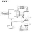
Fig. 2 is a block diagram illustrating abrushless motor 47 driving the variable valve mechanism shown inFig. 1 , amotor control device 50, and anengine control device 51; -
Fig. 3(a), Fig. 3(b), and Fig. 3(c) represent pulse signals output by a first electric angle sensor S1, a second electric angle sensor S2, and a third electric angle sensor S3, respectively, with respect to a motor rotational angle θ; -
Fig. 3(d) and Fig. 3(e) represent pulse signals output by a first position sensor S4 and a second position sensor S5, respectively; -
Fig. 3(f) represents change of an electric angle counter value Ec with respect to the motor rotational angle θ; -
Fig. 3(g) represents change of a position counter value Pg; -
Fig. 3(h) represents change of a stroke counter value Sg; -
Fig. 4 is a flowchart representing a counting procedure performed by themotor control device 50 illustrated inFig. 2 ; -
Fig. 5 is a table representing addition/subtraction of the position counter value ofFig. 3(g) based on the pulse signals ofFigs. 3(d) and 3(e) ; -
Fig. 6 is a flowchart representing a stop/start counting procedure performed by themotor control device 50 ofFig. 2 ; -
Fig. 7 is a flowchart representing a position counter learning procedure performed by themotor control device 50 ofFig. 2 ; -
Fig. 8 is a flowchart representing a displacement determination procedure for the motor rotational angle θ performed by theengine control device 51 illustrated inFig. 2 ; -
Fig. 9 is a graph representing the relationship between a determination period TB and an engine speed NE, which is used in step S430 ofFig. 8 ; -
Fig. 10 is a timing chart representing change of a timer value T and change of a displacement occurrence flag EF when the engine speed NE increases stably after the engine is started; and -
Fig. 11 is a timing chart representing change of the timer value T and change of the displacement occurrence flag EF when the engine speed changes unstably after the engine is started. -
Figs. 1 to 11 show one embodiment of the present invention. The embodiment relates to a control device of avariable valve mechanism 14. The control device includes amotor control device 50 and anengine control device 51. -
Fig. 1 is the cross-sectional view showing the structure of the vicinity of acylinder head 2 of anengine 1. - The
engine 1, which is an internal combustion engine, includes thecylinder head 2, acylinder block 3, and apiston 5. Thecylinder head 2, thecylinder block 3, and thepiston 5 define acombustion chamber 6. Anintake passage 7 and an exhaust passage 8 are connected to thecombustion chamber 6. Communication between theintake passage 7 and thecombustion chamber 6 is selectively permitted and blocked by anintake valve 9, which selectively opens and closes. Communication between the exhaust passage 8 and thecombustion chamber 6 is selectively permitted and blocked by anexhaust valve 10, which selectively opens and closes. - An intake camshaft 11 driving the
intake valve 9 and anexhaust camshaft 12 driving theexhaust valve 10 are arranged on thecylinder head 2. The intake camshaft 11 and theexhaust camshaft 12 are rotated through transmission of rotation of the crankshaft of theengine 1 to thecamshafts 11, 12. The intake camshaft 11 and theexhaust camshaft 12 include anintake cam 11a and anexhaust cam 12a, respectively. Theintake cam 11a and the intake camshaft 11 rotate integrally to selectively open and close theintake valve 9. Theexhaust cam 12a and theexhaust camshaft 12 rotate integrally to selectively open and close theexhaust valve 10. - The
engine 1 has avariable valve mechanism 14 arranged between theintake cam 11a and theintake valve 9. Thevariable valve mechanism 14 varies the maximum lift amount of theintake valve 9 and the duration angle of theintake cam 11a. The maximum lift amount of theintake valve 9 and the duration angle of theintake cam 11a represent the valve actuation parameters of theintake valve 9. Thevariable valve mechanism 14 is controlled in such a manner that, as the necessary intake air amount increases, the maximum lift amount and the duration angle increase. That is, thevariable valve mechanism 14 varies valve actuation parameters of engine valves including theintake valve 9 and theexhaust valve 10. - The
variable valve mechanism 14 has alocker shaft 15, acontrol shaft 16, aninput arm 17, and anoutput arm 18. Thelocker shaft 15 is fixed to thecylinder head 2 and shaped as a pipe extending parallel with the intake camshaft 11. Thecontrol shaft 16 is shaped like a bar and passed through thelocker shaft 15. Theinput arm 17 swings about the axis of thecontrol shaft 16. Theoutput arm 18 swings about the axis in correspondence with swinging of theinput arm 17. - A
roller 19 is rotatably attached to theinput arm 17. Acoil spring 20 presses theroller 19 against theintake cam 11a. Theoutput arm 18 is pressed against thelocker arm 21 when swinging, thus lifting theintake valve 9 through thelocker arm 21. - A first end of the
locker arm 21 is supported by alash adjuster 22 and a second end of thelocker arm 21 contacts theintake valve 9. Thelocker arm 21 is urged toward theoutput arm 18 by thevalve spring 24 of theintake valve 9. As a result, theroller 23 is pressed against theoutput arm 18. In other words, thevalve spring 24 urges theintake valve 9. Theroller 23 is rotatably supported between the first end and the second end of thelocker arm 21. Accordingly, when theinput arm 17 and theoutput arm 18 are caused to swing by rotation of theintake cam 11a, theoutput arm 18 lifts theintake valve 9 through thelocker arm 21, thus selectively opening and closing theintake valve 9. - The
control shaft 16 of thevariable valve mechanism 14 moves axially in such a manner as to change the position of thecontrol shaft 16 relative to the swinging direction of theinput arm 17 and that of theoutput arm 18. This varies the maximum lift angle of theintake valve 9 and the duration angle of theintake cam 11a with respect to theintake valve 9. As theinput arm 17 and theoutput arm 18 are brought closer to each other with respect to the swinging directions, the maximum lift amount of theintake valve 9 and the duration angle of theintake cam 11a both decrease. In contrast, as theinput arm 17 and theoutput arm 18 separate from each other with respect to the swinging directions, the maximum lift amount of theintake valve 9 and the duration angle of theintake cam 11a both increase. - As illustrated in
Fig. 2 , thevariable valve mechanism 14 includes abrushless motor 47, which axially moves thecontrol shaft 16. Themotor control device 50 controls thebrushless motor 47. Themotor control device 50 is connected to theengine control device 51 through acommunication cable 60 in such a manner that mutual communication is allowed between themotor control device 50 and theengine control device 51. Theengine control device 51 controls theengine 1 in various manners. - With reference to
Fig. 2 , thebrushless motor 47 is connected to abasal end 16a of thecontrol shaft 16 through aconversion mechanism 48. Theconversion mechanism 48 converts rotation of thebrushless motor 47 into axial linear movement of thecontrol shaft 16. When thebrushless motor 47 rotates in a set angular range, thecontrol shaft 16 moves axially and thevariable valve mechanism 14 is actuated. The set angular range of thebrushless motor 47 is set to, for example, a range corresponding to ten revolutions of thebrushless motor - As the
brushless motor 47 rotates in a forward direction, thecontrol shaft 16 moves away from thebrushless motor 47. This changes the position of theinput arm 17 and the position of theoutput arm 18 relative to each other with respect to the swinging directions in such a manner that theinput arm 17 and theoutput arm 18 are brought closer to each other. As thebrushless motor 47 rotates in a reverse direction, thecontrol shaft 16 moves toward thebrushless motor 47, thus changing the position of theinput arm 17 and the position of theoutput arm 18 relative to each other with respect to the swinging directions in such a manner that theinput arm 17 and theoutput arm 18 separate from each other. Rotation of thebrushless motor 47 changes the position of theinput arm 17 and the position of theoutput arm 18 relative to each other with respect to the swinging directions. This varies the maximum lift amount of theintake valve 9 and the duration angle of theintake cam 11a. - The stator of the
brushless motor 47 has a first electric angle sensor S1, a second electric angle sensor S2, a third electric angle sensor S3, a first position sensor S4, and a second position sensor S5. The rotor of thebrushless motor 47 has a multipole magnet including four poles and a multipole magnet having 48 poles, in such a manner that the multipole magnets rotate integrally. - When the
brushless motor 47 rotates, the first to third electric angle sensors S1 to S3 output pulse signals the phases of which are offset from one another as illustrated inFigs. 3(a) to 3(c) in correspondence with the magnetic force of the four-pole magnet. The circumferential positions of the first to third electric angle sensors S1 to S3 are determined in such a manner as to obtain such pulse signals. The edge of the pulse signal output by each one of the first to third electric angle sensors S1 to S3 is generated whenever thebrushless motor 47 rotates by 45°. The phase of the pulse signal of the first electric angle sensor S1 proceeds from the phase of the pulse signal of the second electric angle sensor S2 by the amount corresponding to rotation of 30° of thebrushless motor 47. The phase of the pulse signal of the third electric angle sensor S3 is retarded from the phase of the pulse signal of the second electric angle sensor S2 by the amount corresponding to the rotation of 30° of thebrushless motor 47. - When the
brushless motor 47 rotates, the first and second position sensors S4, S5 output pulse signals represented inFigs. 3(d) and 3(e) in correspondence with the magnetic force of the 48-pole magnet. The circumferential positions of the first and second position sensors S4, S5 are determined in such a manner as to obtain the pulse signals having the illustrated waveforms. The edge of the pulse signal output by each one of the first and second position sensors S4, S5 is generated whenever thebrushless motor 47 rotates by 7.5°. The phase of the pulse signal of the first position sensor S4 is offset from the phase of the pulse signal of the second position sensor S5 by the amount corresponding to the rotation of thebrushless motor 47 by 3.75°. - Accordingly, the angular interval between the edges of the pulse signals of the first to third electric angle sensors S1 to S3 is 15°, whereas the angular interval between the edges of the pulse signals of the first and second position sensors S4, S5 is 3.75°, which is shorter. Four edges are generated by the pulse signals of the first and second position sensors S4, S5 in a single interval of the pulse signals of the first to third electric angle sensors S1 to S3.
- As illustrated in
Fig. 2 , themotor control device 50 is electrically connected to the first to third electric angle sensors S1 to S3, the first and second position sensors S4, S5, and thebrushless motor 47. Themotor control device 50 controls thebrushless motor 47 to control thevariable valve mechanism 14. - The
motor control device 50 includes a CPU, a ROM, a RAM, anonvolatile memory 57, and an input/output port. The CPU performs various calculation procedures. The ROM stores programs and data that are necessary for control. The RAM temporarily stores calculation results of the CPU. The input/output port inputs/outputs signals with respect to the exterior. - The
motor control device 50 detects the relative rotational angle of thebrushless motor 47 based on the pulse signals of the position sensors S4, S5. The motor control device then calculates the absolute rotational angle of thebrushless motor 47 based on the relative rotational angle and a reference position, which has been learned in advance. Themotor control device 50 rotates thebrushless motor 47 by switching power supply among energizing phases such as the U phase, the V phase, and the W phase in correspondence with the patterns of the pulse signals of the first to third electric angle sensors S1 to S3. - The
engine control device 51 also includes a CPU, a ROM, a RAM, and an input/output port. Various signals are input from themotor control device 50 to the input port of theengine control device 51 through thecommunication cable 60. Further, the followings are connected to the engine control device 51: - an accelerator sensor 52, which detects the depression amount of an accelerator pedal depressed by the driver of the vehicle, or the accelerator operating amount ACCP;
- a
throttle sensor 53, which detects the opening degree of a throttle valve arranged in theintake passage 7 of theengine 1, or the throttle opening degree TA; - an
air flowmeter 54, which detects the amount of the air drawn into thecombustion chamber 6 via theintake passage 7, or the intake air amount GA; - a
crank angle sensor 55, which outputs a signal corresponding to rotation of the output shaft of theengine 1 in order to detect the engine speed NE; and - an
ignition switch 56 manipulated by the driver of the vehicle to output a signal corresponding to a current switch position. - The
engine control device 51 also includes atimer 58. Thetimer 58 measures the period in which the engine speed NE is higher than or equal to a threshold value NA. - When the
ignition switch 56 is switched on, or the ignition is turned on, the power is supplied from abattery 70 to themotor control device 50 and theengine control device 51. This starts mutual communication between themotor control device 50 and theengine control device 51 through thecommunication cable 60. Also, a starting motor is activated to start operation of theengine 1. When theignition switch 56 is switched off, or the ignition is turned off, the power supply to themotor control device 50 and theengine control device 51 is blocked and theengine 1 is stopped after a prescribed procedure is completed. - The
engine control device 51 acquires the operating state of theengine 1 based on detection signals from various sensors and various signals from themotor control device 50. Theengine control device 51 outputs a command value to themotor control device 50 in order to drive thebrushless motor 47 in correspondence with the operating state of theengine 1. Themotor control device 50 drives thebrushless motor 47 based on the command value. This moves thecontrol shaft 16 axially, thus allowing thevariable valve mechanism 14 to control the valve actuation parameters of theintake valve 9. - The valve actuation parameters of the
intake valve 9 correspond to the axial position of thecontrol shaft 16, or the motor rotational angle θ. Accordingly, in order to precisely control the valve actuation parameters of theintake valve 9, it is important to accurately detect the motor rotational angle θ and operate thebrushless motor 47 in such a manner that the motor rotational angle θ represents a value corresponding to target valve actuation parameters. - The timing chart of
Fig. 3 and the flowchart ofFig. 4 each represent a detection procedure for the motor rotational angle θ of the present embodiment. -
Figs. 3(a) to 3(c) represent the pulse signals output by the first to third electric angle sensors S1 to S3 with respect to the motor rotational angle θ.Figs. 3(d) and 3(e) represent the pulse signals output by the first and second position sensors S4, S5.Fig. 3(f) represents change of the electric angle counter value Ec with respect to the motor rotational angle θ.Fig. 3(g) represents change of the position counter value Pg.Fig. 3(h) represents change of the stroke counter value Sg. The position counter P shows a detection position counter value Pk. The electric angle counter value Ec is a counter value of an electric angle counter E. The position counter value Pg is a counter value of a position counter P. The stroke counter value Sg is a counter value of a stroke counter S. - Using the electric angle counter E, the energizing phases of the
brushless motor 47 are switched to operate thebrushless motor 47. The position counter value Pg represents the axial movement amount of thecontrol shaft 16 after the ignition is turned on. In other words, the position counter value Pg represents the change of the relative rotational angle of thebrushless motor 47 after the ignition is turned on. The stroke counter value Sg represents the axial position of thecontrol shaft 16 with reference to the state in which thecontrol shaft 16 is moved maximally toward the limit of movement corresponding to adistal end 16b. When thecontrol shaft 16 is located at the limit of movement corresponding to thedistal end 16b, the maximum lift amount of theintake valve 9 and the duration angle of theintake cam 11a are both minimum. That is, the stroke counter value Sg represents the motor rotational angle θ with reference to the end of the set angular range of thebrushless motor 47. In other words, the stroke counter value Sg represents the absolute rotational angle of thebrushless motor 47. -
Fig. 4 represents a counting procedure by which the electric counter value Ec, the position counter value Pg, and the stroke counter value Sg are changed. Themotor control device 50 operates by a cycle shorter than the interval between the edges of the pulse signals of the first and second position sensors S4, S5. Themotor control device 50, which performs the counting procedure, configures a detecting portion. - Once the counting procedure for each one of the electric angle counter value Ec, the position counter value Pg, and the stroke counter value Sg is started, the
motor control device 50 changes the electric angle counter value Ec in step S101 as represented inFig. 3(f) , based on the output pattern of the pulse signals of the first to third electric angle sensors S1 to S3, which are represented inFigs. 3(a) to 3(c) . - When the
brushless motor 47 rotates in a forward direction (a rightward direction as viewed inFig. 3 ), successive integer values in the range of 0 to m are assigned to the electric angle counter value Ec in the ascending order in correspondence with the output patterns of the pulse signals of the first to third electric angle sensors S1 to S3. In the present embodiment, m is 5. The electric angle counter value Ec is assigned with 0 → 1 → 2 → 3 → 4 → 5 → 0 in this order. - When the
brushless motor 47 rotates in a reverse direction (a leftward direction as viewed inFig. 3 ), successive integer values in the range of 0 to m are assigned to the electric angle counter value Ec in the descending order in correspondence with the output patterns of the pulse signals of the first to third electric angle sensors S1 to S3. In the present embodiment, the electric counter value Ec is assigned with 5 → 4 → 3 → 2 → 1 → 0 → 5 in this order. Thebrushless motor 47 is rotated in the forward direction or the reverse direction by switching the energizing phases of thebrushless motor 47 based on the electric angle counter value Ec. - In step S102, the
motor control device 50 selectively increases and decreases the position counter value Pg in correspondence with the output pattern of the pulse signals of the first and second position sensors S4 and S5. - With reference to
Fig. 5 , the position counter value Pg is selectively incremented and decremented by 1 in correspondence with combination of a high level H, a low level L, a rising edge ↑, and a falling edge ↓ of the pulse signals of the first and second position sensors S4 and S5. In other words, the position counter value Pg is the count of the edges of the pulse signals of the first and second position sensors S4, S5. - When the
brushless motor 47 rotates forward, the position counter value Pg is incremented by 1 for each edge of the pulse signals of the first and second position sensors S4 and S5, which are illustrated inFigs. 3(d) and 3(e) , and proceeds rightward as viewed inFig. 3(g) . When thebrushless motor 47 rotates reversely, the position counter value Pg is decremented by 1 for every edge and proceeds leftward as viewed inFig. 3(g) . When theignition switch 56 is switched off, or the ignition is turned off, the position counter P is reset so that the counter P shows 0. Accordingly, the position counter value Pg represents the axial movement amount of thecontrol shaft 16, or the change of the motor rotational angle θ, which are caused after the ignition is turned on. - The stroke counter value Sg represented in
Fig. 3(h) is changed in correspondence with the change of the position counter value Pg represented inFig. 3(g) . Specifically, in step S103, themotor control device 50 calculates a detection position counter value Pk by adding a correction value ΔP to the position counter value Pg. In step S104, themotor control device 50 obtains the stroke counter value Sg by adding a value -Pr, which is a learned value Pr with a reversed sign, to the detection position counter value Pk. In other words, the following equations are satisfied: Pk = Pg + ΔP, Sg = Pk - Pr. In an initial state, the correction value ΔP is 0. - The learned value Pr is the detection position counter value Pk in the state in which the
control shaft 16 is moved to the limit of movement corresponding to thedistal end 16b of the movable range, or the motor rotational angle θ is changed to the limit of movement of the set angular range. In other words, the learned value Pr is an initial value of the motor rotational angle θ. The learned value Pr is learned under prescribed conditions after the ignition is turned on and stored in thenonvolatile memory 57. The stroke counter value Sg represents the axial position of thecontrol shaft 16 with reference to the state in which thecontrol shaft 16 is moved to the limit of movement corresponding to thedistal end 16b. In other words, the stroke counter value Sg represents the motor rotational angle θ with reference to the limit of movement of the set angular range of thebrushless motor 47. - The
motor control device 50 detects the motor rotational angle θ based on the stroke counter value Sg. To control the valve actuation parameters of theintake valve 9 by operating thevariable valve mechanism 14, themotor control device 50 operates thebrushless motor 47 in such a manner that the detection value θd of the motor rotational angle θ becomes a value corresponding to the target valve actuation parameters commanded by theengine control device 51. As a result, the valve actuation parameters of theintake valve 9 are precisely controlled to achieve the target. - The
motor control device 50 stores the position counter value Pg in thenonvolatile memory 57 before the position counter value Pg is reset to 0 when the ignition is turned off. Then, after the ignition is turned on, themotor control device 50 reads out the position counter value Pg from thenonvolatile memory 57 and resumes counting the position counter value Pg. After theengine 1 is restarted, the stroke counter value Sg, which is set in correspondence with the position counter value Pg, corresponds to the motor rotational angle θ. - For example, if the position counter value Pg remains 0 after counting of the position counter value Pg is resumed, the stroke counter value Sg, which is set in correspondence with the position counter value Pg, may not correspond to the motor rotational angle θ. However, this problem is solved by the present embodiment.
- However, the motor rotational angle θ may change due to mechanical looseness in the period from when the ignition is turned off to stop the engine to when the ignition is turned on to restart the engine. In this case, the motor rotational angle θ at the time when the engine is restarted does not correspond to the position counter value Pg, which was stored when the engine was stopped. That is, the position counter value Pg, counting of which is resumed after the engine is restarted, may be displaced from the value corresponding to the motor rotational angle θ.
- With reference to
Fig. 3(g) , if, for example, the ignition is turned off when the position counter value Pg is 29, the position counter value Pg of 29 is stored in thenonvolatile memory 57. Assume that the actual value θr of the motor rotational angle θ is changed by the amount of -13 in the reverse rotational direction (leftward as viewed inFig. 3 ) due to the influence of the mechanical looseness on thebrushless motor 47 in the period in which the engine is maintained in a stopped state, as indicated by the arrow AR inFig. 3(g) . That is, assume that the position counter value Pg of 29 corresponding to the detection value θd of the motor rotational angle θ does not coincide with the actual value θr of 16 of the motor rotational angle θ. In this case, the position counter value Pg of 29 is greater than thevalue 16 corresponding to the actual value θr of the motor rotational angle θ by the difference of 13. - For example, if the position counter value Pg of 29 is set to the initial value of the position counter value Pg when the ignition is turned on, the stroke counter value Sg, which is set in correspondence with the position counter value Pg, does not correspond to the actual value θr of the motor rotational angle θ. In this case, with reference to
Fig. 3(h) , the stroke counter value Sg may be 344, which is greater than 331, the value corresponding to the actual axial position of thecontrol shaft 16, by the difference of 13. The detection value θd of the motor rotational angle θ obtained in correspondence with the stroke counter value Sg of 344 does not represent the actual value θr, or is inaccurate. When, as in this case, the detection value θd of the motor rotational angle θ is inaccurate, it is impossible to accurately control thebrushless motor 47 in such a manner that the valve actuation parameters of theintake valve 9 achieve the target actuation parameters. This may disadvantageously influence operation of theengine 1. - To solve this problem, the
motor control device 50 of the present embodiment operates in such a manner that the position counter value Pg at the time when the ignition is turned on corresponds to the actual value θr of the motor rotational angle θ by carrying out the stop/start counting procedure. The stop/start counting procedure, or a stop/start position counting procedure, includes the following procedures, such as a first procedure PR1, a second procedure PR2, and a third procedure PR3. In the first to third procedures PR1 to PR3, the correction value ΔP in step S103 ofFig. 4 is calculated in such a manner that the detection position counter value Pk corresponds to the actual value θr of the motor rotational angle θ. As a result, themotor control device 50 acquires the actual value θr of the motor rotational angle θ, which has changed in the period from when the ignition is turned off to when the ignition is turned on. - In the first procedure PR1, the
motor control device 50 calculates a first counter value Eg and a second counter value Ei. The first counter value Eg is an electric angle counter value at the time when the ignition is turned off and the second counter value Ei is an electric angle counter value at the time when the ignition is turned on for the first time after the ignition is turned off. In other words, the first counter value Eg represents the electric angle counter value at the time immediately before the power supply to themotor control device 50 is stopped. The second counter value Ei represents the electric angle counter value at the time immediately after the power supply to themotor control device 50 is started. - The second counter value Ei is obtained when the ignition is turned on. Specifically, the electric angle counter value Ec varies in correspondence with the output pattern of the first to third electric angle sensors S1 to S3 and is determined in correspondence with the output pattern even immediately after the ignition is turned on. The second counter value Ei is stored in the
nonvolatile memory 57 whenever the ignition is turned on. - Also in the first procedure PR1, the
motor control device 50 calculates a change equivalent value X using the equation (1), which will be described later. The change equivalent value X is a change of the position counter value Pg converted from the change of the actual value θr of the motor rotational angle θ that is caused in the period in which the engine is held in a stopped state. - In the second procedure PR2, the
motor control device 50 calculates the correction value ΔP. The correction value ΔP is used to correct the current position counter value Pg stored in thenonvolatile memory 57. In other words, the position counter value Pg is corrected using the correction value ΔP in such a manner that the position counter value Pg corresponds to the actual value θr of the motor rotational angle θ. The correction value ΔP is obtained by the following equation: ΔP = X - Pg. In other words, the correction value ΔP is the difference between the change equivalent value X and the current position counter value Pg. In the example ofFig. 3 , the change equivalent value X is 13, the current position counter value Pg is 29, and the corrected position counter value Pg is 16. - In the third procedure PR3, the
motor control device 50 corrects the position counter value Pg when the ignition is turned on. That is, when the ignition is turned on, the correction value ΔP is added to the position counter value Pg, which was reset to 0 when the ignition was turned off. The corrected position counter value Pg is set as the detection position counter value Pk, using which the motor rotational angle θ is detected. The detection position counter value Pk is set in step S103 ofFig. 4 . - By performing the first to third procedures PR1 to PR3, the detection position counter value Pk is changed by the amount corresponding to the correction value ΔP with respect to the position counter P at the time when the ignition has been turned on. Accordingly, the detection position counter value Pk corresponds to the actual value θr of the motor rotational angle θ. The motor rotational angle θ is accurately detected based on the stroke counter value Sg, which is set in accordance with the detection position counter value Pk.
- The following is the equation (1) in the first procedure PR1:

- In the equation (1), n represents the number of edges of a pulse signal. The number of edges n represents the number of the pulse signals output by the first and second position sensors S4, S5 in the interval between the edges of the pulse signals of the first to third electric angle sensors S1 to S3. In the present embodiment, the number of edges n = 4. The term (Eg - Ei)·n of the equation (1) is a position counter value Pg converted from the difference between the first counter value Eg and the second counter value Ei. If the position counter value Pg at the time when the ignition has been turned off is a value at the time when an edge occurs in the pulse signal of any one of the first to third electric angle sensors S1 to S3, that is, for example, the position counter value Pg is 28, the term (Eg - Ei)·n is employed as the change equivalent value X without being changed.
- If the position counter value Pg is not a value at the time when an edge occurs in the pulse signal of any one of the first to third electric angle sensors S1 to S3, which is, for example, 28, the term (Eg - Ei)·n is displaced from the accurate change equivalent value X by the amount corresponding to the difference between the position counter value Pg and the value at the occurrence of the edge. If the position counter value Pg is 29 as in the example of
Fig. 3 , the difference between the position counter value Pg and the value at the edge 28 is 1. In this case, the term (Eg - Ei)·n is displaced from the accurate change equivalent value X by the amount corresponding to thedifference 1. The difference between the term (Eg - Ei)·n and the accurate change equivalent value X coincides with the remainder AR when the position counter value Pg at the time when the ignition has been turned off is divided by the number of edges n, 4. Accordingly, the change equivalent value X is accurately obtained by adding the remainder AR to the term (Eg - Ei)·n, as represented by the equation (1). -
Fig. 6 represents a procedure of the position counter P carried out when theignition switch 56 is turned off or on. Themotor control device 50 performs the stop/start counting procedure by a cycle shorter than the interval between the edges of the pulse signals of the first and second position sensors S4, S5. Themotor control device 50, which carries out the stop/start counting procedure, configures a calculating portion. - In the stop/start counting procedure, the
motor control device 50 determines whether the current point of time is a point immediately after theignition switch 56 has been switched off from an ON state in step S201. If positive determination is made in step S201, thenonvolatile memory 57 stores the position counter value Pg as the position counter value Pg at the time when the ignition is turned off. Step S203 is then carried out. - In step S203, the
nonvolatile memory 57 stores the electric angle counter value Ec as the first counter value Eg. Then, in step S204, themotor control device 50 resets the position counter P to 0 and ends the stop/start counting procedure. - If the determination of step S201 is negative, the
motor control device 50 determines whether the current point of time is a point immediately after theignition switch 56 has been turned on from an OFF state in step S205. If the determination of step S205 is positive, themotor control device 50 calculates the change equivalent value X by performing the first procedure PR1 in step S206 and the correction value ΔP by carrying out the second procedure PR2 in step S207. The stop/start counting procedure is then ended. - The flowchart of
Fig. 7 represents a position counter learning procedure. Specifically, the flowchart represents a learning procedure of the learned value Pr, or an initial position learning procedure, and a procedure for removing, or subtracting, the correction value ΔP from the detection position counter value Pk after the learned value Pr is learned. Themotor control device 50 performs the position counter learning procedure by a cycle shorter than the interval between the edges of the pulse signals of the first and second position sensors S4, S5. - In the position counter learning procedure, the
motor control device 50 performs step S303 to learn the learned value Pr if learning of the learned value Pr after the ignition has been turned on is incomplete, that is, if the determination of step S301 is positive and the determination of step S302 is positive. In other words, themotor control device 50 carries out step 303 to learn the learned value Pr if any learned value Pr has not been written in thenonvolatile memory 57 after the ignition was turned on and conditions for learning are met. - One of the conditions for learning in step S302 is that the
engine 1 is in a fuel cut-off control. Specifically, theengine 1 being in the fuel cut-off control reduces the influence of movement of thecontrol shaft 16, which is moved to the limit of movement, on the operating state of theengine 1. This is advantageous for learning the learned value Pr. - First, in step S303, the
motor control device 50 moves thecontrol shaft 16 to the limit of movement corresponding to thedistal end 16b. In other words, the motor rotational angle θ is moved to the limit of movement of the set angular range. - Then, in step S304, the
motor control device 50 determines whether thecontrol shaft 16 has reached the limit of movement based on whether, for example, change of the position counter P is not to happen any more. When positive determination is made in step S304, or it is determined that thecontrol shaft 16 has reached the limit of movement, themotor control device 50 stores the detection position counter value Pk in this state in thenonvolatile memory 57 as the learned value Pr. This completes learning of the learned value Pr. - The learned value Pr stored in the
nonvolatile memory 57 is added, with a reversed sign, to the detection position counter value Pk in step S104 ofFig. 4 . The sum is set as the stroke counter value Sg. After the ignition is turned on, the learned value Pr is learned when the detection position counter value Pk corresponds to the addition of the correction value ΔP and the counter value of the position counter P. Accordingly, when the learned value Pr, which is stored in thenonvolatile memory 57 as a learned result, is reflected in the counter value of the stroke counter S, the stroke counter value Sg reflects the correction value ΔP. However, once the learned value Pr is learned, or stored in thenonvolatile memory 57, the correction value ΔP included in the detection position counter value Pk is unnecessary. Specifically, when the correction value ΔP is included in the detection position counter value Pk, the stroke counter value Sg, which is set based on this count, is inappropriate. This causes inaccuracy in the detection value θd of the motor rotational angle θ, which is based on the stroke counter value Sg. - To avoid this problem, in the position counter learning procedure, the
motor control device 50 sets the correction value ΔP to 0 in step S306 after the learning of the learned value Pr of steps S303 to S305 is completed. As a result, the correction value ΔP is subtracted from the detection position counter value Pk and the above-described problem is avoided. - When the
engine 1 operates, a movable portion of thevariable valve mechanism 14, such as thecontrol shaft 16, may be displaced unexpectedly due to mechanical instability or by receiving reactive force from thevalve spring 24. In this case, the actual value θr of the motor rotational angle θ does not coincide with the detection value θd. To solve this problem, in the present embodiment, theengine control device 51 performs a displacement determination procedure when it is highly likely that the actual value θr of the motor rotational angle θ changes unexpectedly, that is, when theengine 1 is operating and themotor control device 50 is not being powered. In the displacement determination procedure, theengine control device 51 determines whether the detection value θd of the motor rotational angle θ is displaced from the actual value θr. -
Fig. 8 represents the flowchart of the displacement determination procedure. Theengine control device 51, which performs this procedure cyclically, configures a determining portion. - In the displacement determination procedure, the
engine control device 51 determines whether themotor control device 50 is being powered in step S400. - The
engine control device 51 determines whether themotor control device 50 is in a non-powered state by determining whether mutual communication between themotor control device 50 and theengine control device 51 is disabled. If the determination of step S400 is negative, that is, if themotor control device 50 is in the non-powered state, theengine control device 51 switches a communication disruption flag TF to 1 and performs step S410. If the determination of step S400 is positive, that is, if themotor control device 50 is in a powered state, theengine control device 51 switches the communication disruption flag TF to 0. - In step S410, the
engine control device 51 determines whether the current engine speed NE is higher than or equal to a threshold value NA. If the determination of step S410 is positive, that is, if the engine speed NE is higher than or equal to the threshold value NA, theengine control device 51 carries out step S420 and starts thetimer 58. - If the determination of step S410 is negative, that is, if the engine speed NE is less than the threshold value NA, the
engine control device 51 performs step S460 and stops thetimer 58. Specifically, after thetimer 58 is switched from the operating state to the stopped state, thetimer 58 maintains the current timer value T. If thetimer 58 has been held in the stopped state, thetimer 58 is maintained in this state. Afterwards, theengine control device 51 suspends the displacement determination procedure. - When positive determination is made in step S410, that is, when the engine speed NE is higher than or equal to the threshold value NA, the
engine control device 51 carries out step S420 and starts thetimer 58. Theengine control device 51 then performs step S430. Thetimer 58, which has been stopped in step 460 in the previous cycle, is restarted. Counting of the timer value T is resumed from the counter value maintained in step S460. Specifically, the timer value T represents the accumulated time of the periods in which themotor control device 50 is in the non-powered state and the engine speed NE is higher than or equal to the threshold value NA. Theengine control device 51, which performs steps S410, S420, and S460 and thetimer 58 each configure a measuring portion. - In step S430, the
engine control device 51 determines whether the timer value T is greater than or equal to a determination period TB. The determination period TB is set to a time longer than one cycle of the electric angle counter E. The cycle of the electric angle counter E represents one cycle of the electric angle counter value Ec, which is 0 → 1 → 2 → 3 → 4 → 5. As illustrated inFig. 9 , the determination period TB becomes shorter as the engine speed NE becomes higher. The determination period TB is set in this manner since it is assumed that, when theengine 1 is operating and themotor control device 50 is in the non-powered state, likeliness that the actual value θr of the motor rotational angle θ increases becomes greater as the engine speed NE becomes higher. - If the determination of step S430 is negative, that is, if the timer value T is less than the determination period TB, the
engine control device 51 suspends the displacement determination procedure. - If the determination of step S430 is positive, that i, if the timer value T is greater than or equal to the determination period TB, the
engine control device 51 performs step S440 and switches the displacement occurrence flag EF to 1. Theengine control device 51 then carries out step S450, or initializes the timer value T to 0, and suspends the displacement determination procedure. - The determination of step S440 is based on the following two facts:
- that it is considered definite that the
engine 1 is operating when the period in which the engine speed NE is higher than or equal to the threshold value NA is long to a certain extent; and - that it is considered that the detection value θr of the motor rotational angle θ is displaced from the actual value θr if the
motor control device 50 is in the non-powered state when it is determined that theengine 1 is operating. - After detecting that the displacement occurrence flag EF is 1, the
motor control device 50, which is in the powered state, performs the position counter learning procedure ofFig. 7 . As a result, themotor control device 50 causes the detection result θd of the motor rotational angle θ to be equal to the actual value θr. - When the determination of step S400 is positive, the
engine control device 51 proceeds to step S470, and determines whether thetimer 58 is operating. If the determination of step S470 is negative, that is, if thetimer 58 is stopped, theengine control device 51 suspends the displacement determination procedure. - If the determination of step S470 is positive, that is, if the
timer 58 is operating, theengine control device 51 carries out step 480 and stops thetimer 58. Theengine control device 51 then performs step S490 to initialize the timer value T to 0. Then, in step S500, theengine control device 51 operates themotor control device 50 to perform the stop/start counting procedure ofFig. 6 when themotor control device 50 is switched to the powered state. Afterwards, theengine control device 51 suspends the displacement determination procedure. -
Fig. 10 represents the result of the displacement determination procedure when the engine speed NE stably increases after theengine 1 has been started. - Basically, the power supply to the
engine control device 51 and themotor control device 50 is started when the ignition is turned on. In other words, the communication disruption flag TF is maintained as 0. However, in the case ofFig. 10 , since themotor control device 50 is maintained in the non-powered state after the ignition is turned on, the determination of step S400 is negative at time point t1. The communication disruption flag TF is switched from 0 to 1. - When the engine speed NE becomes higher than or equal to the threshold value NA at time point t2 after the starting motor is actuated and the
engine 1 is started, positive determination is made in step S410 and thetimer 58 is started in step S430. In the case ofFig. 10 , the timer value T continuously increases since the engine speed NE is maintained as a value higher than the threshold value NA after time point t2. - When the timer value T reaches the determination period TB at time point t3, positive determination is caused in step S430 and the displacement occurrence flag EF is switched from 0 to 1 in step S440. In other words, the
engine control device 51 determines that the actual value θr of the motor rotational angle θ is displaced from the detection value θd. Afterwards, when themotor control device 50 is switched to the powered state, themotor control device 50 performs the position counter learning procedure, so that the detection value θd of the motor rotational angle θ coincides with the actual value θr. - As indicated by the single-dotted chain lines in
Fig. 10 , when themotor control device 50 is switched from the non-powered state to the powered state in the period from time point t2 to time point t3, positive determination is made in step S4400 and then in step S470. Subsequently, in step S480, theengine control device 51 initializes the timer value T to 0. Afterwards, when themotor control device 50 is switched to the powered state, themotor control device 50 carries out the stop/start counting procedure, and to cause the detection value θd of the motor rotational angle θ to be equal to the actual value θr. -
Fig. 11 represents the result of the displacement determination procedure when the engine speed NE increases while unstably fluctuating after theengine 1 is started. Specifically, the engine speed NE repeatedly exceeds and falls short of the threshold value NA. When the engine speed NE becomes higher than or equal to the threshold value NA for the first time after the starting motor is actuated, theengine control device 51 starts thetimer 58 and increases the timer value T. When the engine speed NE becomes less than the threshold value NA at time point t2, theengine control device 51 temporarily stops thetimer 58. Thetimer 58 maintains the timer value T that has been counted immediately before stopping of thetimer 58. When the engine speed NE recovers a level higher than or equal to the threshold value NA at time point t3, thetimer 58 starts operating and increases the timer value T from the maintained value. When the timer value T reaches the determination period TB at time point t4 after operation of thetimer 58 is repeatedly started and suspended, the displacement occurrence flag EF is switched from 0 to 1. Afterwards, when themotor control device 50 is switched to the powered state, themotor control device 50 performs the position counter learning procedure to cause the detection value θd of the motor rotational angle θ to be equal to the actual value θr. - Although not illustrated in
Fig. 11 , when themotor control device 50 is switched to the powered state before time point t4 as in the case ofFig. 10 , or themotor control device 50 is switched to the powered state before the timer value T reaches the determination period TB, the timer value T is initialized. Afterwards, when themotor control device 50 is switched to the powered state, themotor control device 50 performs the stop/start counting procedure to cause the detection result θd of the motor rotational angle θ to equal to the actual value θr. - As has been described, the determination period TB of the present embodiment is set to a time longer than one cycle of the electric angle counter E. Accordingly, when the second counter value Ei is a value within one cycle from the first counter value Eg, the difference between the detection value θd and the actual value θr of the motor rotational angle θ is obtained appropriately through the stop/start counting procedure. When the second counter value Ei is a value exceeding the cycle from the first counter value Eg, it is determined that the detection value θd of the motor rotational angle θ is displaced from the actual value θr through the displacement determination procedure. Accordingly, even if inappropriate calculation of the change equivalent value X in the stop/start counting procedure causes displacement of the detection value θd of the motor rotational angle θ with respect to the actual value θr, such displacement is detected.
- The engine speed NE is measured, the engine speed NE is compared with the threshold value NA, and the period in which the engine speed NE exceeds the threshold value NA is measured generally by a relatively simple structure. In the present embodiment, the period in which the engine speed NE exceeds the threshold value NA is measured as the timer value T and, when the timer value T is greater than or equal to the determination period TB, it is determined that the
engine 1 is operating. Specifically, if the non-powered state of themotor control device 50 is detected when theengine control device 51 determines that theengine 1 is operating, theengine control device 51 determines that the detection value θd of the motor rotational angle θ is displaced from the actual value θr. Accordingly, theengine control device 51 is capable of determining whether the detection value θd of the motor rotational angle θ is displaced from the actual value θr appropriately and by a simple structure. - The present embodiment has the following advantages.
- (1) The
engine control device 51 detects the powered state of themotor control device 50 and the operating state of theengine 1. When theengine control device 51 detects that theengine 1 is in the operating state and themotor control device 50 is in the non-powered state, theengine control device 51 determines that the detection value θd of the motor rotational angle θ is displaced from the actual value θr. That is, theengine control device 51 effectively determines that the detection value θd of the motor rotational angle θ of thebrushless motor 47, which drives thevariable valve mechanism 14, is displaced from the actual value θr. - (2) The
engine control device 51 counts the timer value T, which is the accumulated time of the periods in which the engine speed NE exceeds the threshold value NA, which is set in advance. When theengine control device 51 detects that the timer value T is greater than or equal to the determination period TB and themotor control device 50 is in the non-powered state, theengine control device 51 determines that the detection value θd of the motor rotational angle θ is displaced from the actual value θr. Accordingly, determination whether the detection value θd of the motor rotational angle θ is displaced from the actual value θr is carried out appropriately and by a simple structure. - (3) Even when the engine speed NE is unstable as in the state in which the
engine 1 is being started, theengine control device 51 obtains the sum of the time in which the engine speed NE exceeds the threshold value NA as the timer value T. This allows theengine control device 51 to appropriately determine whether the detection value θd of the motor rotational angle θ is displaced from the actual value θr, even if the engine speed NE rises unstably. - (4) The
engine control device 51 sets the determination period TB to a shorter time as the engine speed NE becomes higher. This allows theengine control device 51 to appropriately set the time needed for the displacement determination procedure. - (5) The
engine control device 51 is connected to themotor control device 50 through thecommunication cable 60, which allows mutual communication between theengine control device 51 and themotor control device 50. Theengine control device 51 determines that themotor control device 50 is in the non-powered state by detecting disruption of the mutual communication. This allows theengine control device 51 to appropriately determine that themotor control device 50 is in the non-powered state. - (6) When the
engine control device 51 determines that the detection value θd of the motor rotational angle θ is displaced from the actual value θr, that is, when the determination of step S430 is positive, theengine control device 51 operates themotor control device 50, which is in the powered state, to perform the initial position learning procedure, that is, to perform the position counter learning procedure, ofFig. 7 . Themotor control device 50, which is in the powered state, actuates thebrushless motor 47 to change the motor rotational angle θ to the limit of movement of the set angular range and stores the position counter value Sg in this state as the initial position. This corrects the displacement of the detection value θd of the motor rotational angle θ with respect to the actual value θr. - (7) The
motor control device 50 carries out the stop/start counting procedure ofFig. 6 when the ignition is turned off and when the ignition is turned on. Accordingly, even if the motor rotational angle θ is changed in the period in which theengine 1 is held in the stopped state, themotor control device 50 corrects the detection position counter value Pk when the ignition is turned on, in such a manner that the detection position counter value Pk corresponds to the actual value θr of the motor rotational angle θ. This allows themotor control device 50 to accurately detect the motor rotational angle θ based on the stroke counter value Sg, which is set based on the detection position counter value Pk. In this manner, the following disadvantage is avoided. Specifically, it is possible to avoid inaccurate control of thebrushless motor 47 when thebrushless motor 47 should be controlled to achieve the target valve actuation parameters based on the motor rotational angle θ, which undesirably influences operation of theengine 1. - If the
engine control device 51 does not determine that displacement has occurred in the displacement determination procedure, themotor control device 50 performs the stop/start counting procedure, as represented instep 500 ofFig. 8 , when themotor control device 50 is switched from the non-powered state to the powered state. This allows themotor control device 50 to detect a change in the motor rotational angle θ when theengine 1 is maintained in the stopped state. - The motor rotational angle θ that changes in the period from when the engine has been started to when the power supply to the
motor control device 50 is started is calculated based on the first counter value Eg and the second counter value Ei. Accordingly, even if the power supply to themotor control device 50 is temporarily suspended while theengine 1 is being started, the motor rotational angle θ that changes in the period from when the power supply to themotor control device 50 has been blocked to when such power supply is resumed is obtained when themotor control device 50 is switched to the powered state later. - As a result, the following problem is solved by the stop/start counting procedure. Specifically, when the
engine 1 starts, a drop in the battery voltage or temporary disconnection of the power cable feeding themotor control device 50 may cause the non-powered state of themotor control device 50, which detects the counter value of the position counter P. When in the non-powered state, themotor control device 50 cannot calculate the position counter value Pg. Accordingly, if the actual value θr of the motor rotational angle θ changes when themotor control device 50 is held in the non-powered state, the change of the motor rotational angle θ is not reflected in the count. In this case, when the power supply to themotor control device 50 is resumed and the motor rotational angle θ is detected, the detection value θr of the motor rotational angle θ, or the position counter value Pg, is displaced from the actual value θr. This prevents themotor control device 50 to accurately detect the current valve actuation parameters. However, this problem is solved by the stop/start counting procedure of the present embodiment. - (8) As represented in step S206 of
Fig. 6 , the change equivalent value X is calculated by the stop/start counting procedure using the following equation. - The term (Eg - Ei)·n of the equation (1) is a position counter value Pg converted from the difference between the first counter value Eg, or the electric angle counter value at the time when the ignition has been turned off, and the second counter value Ei, which is obtained later when the ignition is turned on. When the position counter value Pg is not the value at which an edge occurs in the pulse signal of any one of the first to third electric angle sensors S1 to S3, the term (Eg - Ei)·n is displaced from the accurate change equivalent value X by the amount equal to the difference between the position counter value Pg and the value at the edge. The difference between the term (Eg - Ei)·n and the accurate change equivalent value X coincides with the remainderAR when the position counter value Pg at the time when the ignition has been turned off is divided by the number of edges n. Accordingly, by adding the remainder AR to the term (Eg - Ei)·n as indicated by the equation (1), the accurate change equivalent value X is determined.
- (9) As represented in step S206 of
Fig. 6 , in the stop/start counting procedure, the change equivalent value X is calculated based on the second counter value Ei obtained when the ignition is turned on, and the first counter value Eg, which was obtained when the ignition was turned off. The electric angle counter value Ec, which is used to switch the energizing phases of thebrushless motor 47, changes cyclically. Accordingly, the second counter value Ei may be either a value within one cycle from the first counter value Eg or a value exceeding the cycle. When the second counter value Ei exceeds the cycle from the first counter value Eg, the change equivalent value X obtained through calculation may be an error. - To solve this problem, the determination period TB with which the displacement determination procedure of the present embodiment is carried out is set to a time longer than the cycle of the electric angle counter E. Accordingly, when the second counter value Ei is the value exceeding the cycle from the first counter value Eg, it is determined by the stop/start counting procedure whether the detection value θd of the motor rotational angle θ is displaced from the actual value θr. As a result, even when the
motor control device 50, which performs the stop/start counting procedure, cannot calculate the change equivalent value X appropriately, theengine control device 51 of the present embodiment is capable of appropriately determining whether the detection value θd of the motor rotational angle θ is displaced from the actual value θr. - When the second counter value Ei is the value within the cycle from the first counter value Eg, the
motor control device 50, which performs the stop/start counting procedure, appropriately determines the difference between the detection value θd of the motor rotational angle θ and the actual value θr. - (10) After the ignition is turned off, the
control shaft 16 is moved to the limit of movement corresponding to thedistal end 16b and the detection position counter value Pk in this state is stored in thenonvolatile memory 57 as the learned value Pr. This completes learning of the learned value Pr. After such learning, the learned value Pr is added, with a reversed sign, to the counter value of the stroke counter S, that is, in a direct sense, to the detection position counter value Pk. In this state, the stroke counter value Sg reflects the correction value ΔP However, after learning of the learned value Pr, the correction value ΔP included in the detection position counter value Pk is unnecessary. Accordingly, if the stroke counter S were set based on the detection position counter value Pk that includes the correction value ΔP, the stroke counter S would be inappropriate. In this case, the actual value θr of the motor rotational angle θ calculated with the inappropriate stroke counter value Sg would be inaccurate. - To solve this problem, the
motor control device 50 of the present embodiment sets the correction value ΔP to 0 after the learned value Pr is learned. Specifically, themotor control device 50 subtracts the correction value ΔP from the detection position counter value Pk after learning of the learned value Pr. As a result, the above-described problem is solved. - The present embodiment may be modified into the following forms.
- A control device of the
variable valve mechanism 14 does not necessarily have to perform both the stop/start counting procedure and the displacement determination procedure but may carry out only the displacement determination procedure without performing the stop/start counting procedure. Also in this case, theengine control device 51 detects that themotor control device 50 is in the powered state and theengine 1 is in the operating state. When theengine control device 51 detects that theengine 1 is in the operating state and themotor control device 50 is in the non-powered state, theengine control device 51 determines that the detection value θd of the motor rotational angle θ is displaced from the actual value θr. In this case, theengine control device 51 performs the displacement determination procedure even when a motor other than thebrushless motor 47 drives thevariable valve mechanism 14. Further, if the stop/start counting procedure is not carried out, the determination period TB may be shortened. Alternatively, if the stop/start counting procedure is not performed, thetimer 58 may be omitted. In other words, measurement of the time in which the engine speed NE is higher than or equal to the threshold value NA may be omitted. For example, theengine control device 51 may switch the displacement occurrence flag EF to 1 when it is detected that the engine speed NE is higher than 0 and themotor control device 50 is in the non-powered state. - The displacement determination procedure does not necessarily have to be carried out by the
engine control device 51 but may be performed by a device other than theengine control device 51, which is provided specifically for the displacement determination procedure. - The period in which the engine speed NE is higher than or equal to the threshold value NA does not necessarily have to be measured by the
timer 58. Specifically, a counter may be employed. The counter increments its count by a predetermined value, such as 1, when the determination of step S400 ofFig. 8 is negative and the determination of step S410 is positive. Based on the value of this counter, the period in which the engine speed NE is higher than or equal to the threshold value NA may be measured. - The determination period TB may be set in a manner different from the manner represented in
Fig. 9 . Specifically, the determination period TB is not restricted to setting in correspondence with the engine speed NE but may be a constant value. - Determination whether the
motor control device 50 is in the non-powered state is not restricted to determination based on whether mutual communication between themotor control device 50 and theengine control device 51 is disrupted. - If the
motor control device 50 is in the non-powered state after starting of theengine 1 is completed and theengine 1 is switched to normal operation, the detection value θd of the motor rotational angle θ may become displaced from the actual value θr. However, the displacement determination procedure is repeatedly performed in a cyclic manner. This allows theengine control device 51 to appropriately detect displacement in the motor rotational angle θ not only when theengine 1 starts but after theengine 1 is switched to the normal operation. - The integer value m of the electric angle counter value Ec is not restricted to 5. If the integer value m is altered, the number and the positions of the electric angle sensors and the number of the poles of the multipole magnet, which is the detection target of the electric angle sensors, are changed as needed.
- The number of edges n is not restricted to 4. The number of edges n may be changed to an integer value greater than or equal to 2, as long as the detection accuracy of the motor rotational angle θ is ensured. If the number of edges n is altered, the number and the positions of the position counters and the number of the poles of the multipole magnet, which is the detection target of the position sensors, are changed as needed.
- The first and second position sensors S4, S5 are not restricted to the magnetic sensors but may be, for example, optical sensors. For example, a disk with a slit may be formed in the rotor of the
brushless motor 47 in an integrally rotatable manner. A plurality of groups of light emitting elements and a plurality of groups of light receiving elements are arranged in the stator. The shape of a each pulse signal sent by the optical sensors is adjustable in correspondence with the shape of the slit or the number or the positions of the optical sensors. - The
motor control device 50, which performs the position counter learning procedure, does not necessarily have to move thecontrol shaft 16 toward the limit of movement corresponding to thedistal end 16b. Thecontrol shaft 16 may be moved toward the limit of movement corresponding to thebasal end 16a. When thecontrol shaft 16 is located at the limit of movement corresponding to thebasal end 16a, the maximum lift amount of theintake valve 9 and the duration angle of theintake cam 11a are both maximum values. In this case, themotor control device 50 stores the detection position counter value Pk at the time when thecontrol shaft 16 is arranged at the limit of movement corresponding to thebasal end 16a as the learned value Pr. - The valve actuation parameters varied by the
variable valve mechanism 14 do not necessarily have to be those of theintake valve 9 but may be the valve actuation parameters of theexhaust valve 10. Alternatively, thevariable valve mechanism 14 may vary the valve actuation parameters of both theintake valve 9 and theexhaust valve 10. - The
variable valve mechanism 14 is not restricted to varying the maximum lift amount and the duration angle of theintake valve 9. Thevariable valve mechanism 14 may vary any valve actuation parameters, such as the valve opening timing, the valve dosing timing, the valve opening period, or the maximum lift amount, of engine valves such as theintake valve 9 or theexhaust valve 10.
Claims (6)
- A control device (50, 51) of a variable valve mechanism (14), the variable valve mechanism (14) having a brushless motor (47) that varies an actuation parameter of a valve (9) of an internal combustion engine (1), a rotational angle (θ) of the motor (47) being restricted to a set angular range, the control device (50, 51) detecting a current value of the valve actuation parameter based on the motor rotational angle (θ), the control device (50, 51) comprising:a position sensor (S4, S5) that outputs a pulse signal when the motor (47) rotates;a position counter (P) that calculates a position counter value (Pg) by counting edges of the pulse signal;a detecting portion (50), wherein when in a powered state, the detecting portion (50) obtains a detection value (θd) of the motor rotational angle (θ) based on the counter value; anda determining portion (51) that detects an operating state of the engine (1) and the powered state of the detecting portion (50), wherein when detecting that the engine (1) is operating and the detecting portion (50) is in a non-powered state, the determining portion (51) determines that the detection value (θd) of the motor rotational angle (θ) is displaced from the actual value (θr), wherein the determining portion (51) includes a measuring portion (58) that measures a period (T) in which an engine speed (NE) of the engine (1) exceeds a threshold value (NA) that is set in advance, and wherein the determining portion (51) determines that the detection value (θd) of the motor rotational angle (θ) is displaced from the actual value (θr) if the determining portion (51) detects that the period (T) is greater than or equal to a determination period (TB) that is set in advance and the detecting portion (50) is in the non-powered state;electric angle sensors (S1 to S3); anda plurality of electric angle counters (E) each counting an electric angle counter value (Ec) in accordance with which an energizing phase of the brushless motor (47) is switched, the electric angle counter value (Ec) being changed cyclically in correspondence with an output pattern of the pulse signals output by the electric angle sensors (S1 to S3), an interval between the edges of the pulse signals output by the position sensors (S4, S5) being set to a value shorter than an interval between the edges of the pulse signals output by the electric angle sensors (S1 to S3),characterized bya calculating portion (50) provided in the detecting portion (50), the calculating portion (50) calculating a change equivalent value (X) based on a first counter value (Eg) and a second counter value (Ei), the first counter value (Eg) being the electric angle counter value (Ec) at the time when ignition is turned off, the second counter value (Ei) being the electric angle counter value (Ec) at the time when the ignition is turned on for the first time after the ignition is turned off, the change equivalent value (X) being a value obtained by converting, to a counter value of the position counter (P), a change of the motor rotational angle (θ) that is caused in the time from when the ignition is turned off to when the ignition is turned on, and the determination period (TB) being set to a value longer than one cycle of each electric angle counter (E)wherein the calculating portion (50) further calculates a correction value (ΔP), which is the difference between the change equivalent value (X) and the position counter value (Pg) at the time when the ignition is turned off, the correction value (ΔP) being a value that is used for correcting the position counter value (Pg) such that the position counter value (Pg) corresponds to the actual value (θr) of the motor rotational angle (θ).
- The control device (50, 51) according to claim 1,
wherein the measuring portion (58) calculates an accumulated time (T) of the period (T), and
wherein, when it is detected that the accumulated time (T) is greater than or equal to the determination period (TB) and that the detecting portion (50) is in the non-powered state, the determining portion (51) determines that the detection value (θd) of the motor rotational angle (θ) is displaced from the actual value (θr). - The control device according to claims 1 or 2, wherein the determination period (TB) becomes shorter as the engine speed (NE) becomes higher.
- The control device (50, 51) according to any one of claims 1 to 3, further comprising a communication cable (60) that connects the detecting portion (50) to the determining portion (51) in order to cause mutual communication between the detecting portion (50) and the determining portion (51),
wherein the determining portion (51) determines that the detecting portion (50) is in the non-powered state by determining that the mutual communication is disrupted. - The control device (50, 51) according to claim 1,
wherein the electric angle counters (E) assign sequential integer values of a range of 0 to m to the electric angle counter value (Eg) in an ascending order in correspondence with the output pattern of the pulse signals of the electric angle sensors (S1 to S3) when the brushless motor (47) rotates in a forward direction and in a descending order when the brushless motor (47) rotates in a reverse direction, and
wherein the calculating portion (50) calculates the change equivalent value (X) by adding, to a value obtained by multiplying the difference between the first counter value (Eg) and the second counter value (Ei) by a number of edges (n), the remainder when the position counter value (Pg) at the time immediately before the ignition is turned off is divided by the number of edges (n), the number of edges (n) being the number of the edges of the pulse signals output by the position sensors (S4, S5) in each interval between the edges of the pulse signals output by the electric angle sensors (S1 to S3). - The control device (50, 51) according to any one of claims 1 to 5, wherein, when determining that the detection value (θd) of the motor rotational angle (θ) is displaced from the actual value (θr), the control device (50, 51) performs initial position learning after the power supply to the detecting portion (50) is started, rotates the motor (47) to a limit of movement of the set angular range, and stores, as an initial position, the position counter value (Pg) at the time when the motor (47) is located at the limit of movement.
Applications Claiming Priority (2)
| Application Number | Priority Date | Filing Date | Title |
|---|---|---|---|
| JP2006352708A JP4655036B2 (en) | 2006-12-27 | 2006-12-27 | Control device for variable valve mechanism |
| PCT/JP2007/074891 WO2008078756A1 (en) | 2006-12-27 | 2007-12-26 | Control device for variable valve mechanism |
Publications (3)
| Publication Number | Publication Date |
|---|---|
| EP2098705A1 EP2098705A1 (en) | 2009-09-09 |
| EP2098705A4 EP2098705A4 (en) | 2012-02-01 |
| EP2098705B1 true EP2098705B1 (en) | 2012-11-28 |
Family
ID=39562546
Family Applications (1)
| Application Number | Title | Priority Date | Filing Date |
|---|---|---|---|
| EP07860120A Not-in-force EP2098705B1 (en) | 2006-12-27 | 2007-12-26 | Control device for variable valve mechanism |
Country Status (5)
| Country | Link |
|---|---|
| US (1) | US8205584B2 (en) |
| EP (1) | EP2098705B1 (en) |
| JP (1) | JP4655036B2 (en) |
| CN (1) | CN101573519B (en) |
| WO (1) | WO2008078756A1 (en) |
Families Citing this family (13)
| Publication number | Priority date | Publication date | Assignee | Title |
|---|---|---|---|---|
| JP4525797B2 (en) * | 2008-05-23 | 2010-08-18 | トヨタ自動車株式会社 | Abnormality judgment device for valve characteristic change mechanism |
| JP5201274B2 (en) * | 2010-01-15 | 2013-06-05 | トヨタ自動車株式会社 | Valve working angle variable system |
| JP5115592B2 (en) * | 2010-06-10 | 2013-01-09 | トヨタ自動車株式会社 | Variable valve operating device for internal combustion engine |
| JP2011256802A (en) * | 2010-06-10 | 2011-12-22 | Toyota Motor Corp | Variable valve system for internal combustion engine |
| JP5787058B2 (en) * | 2011-03-10 | 2015-09-30 | トヨタ自動車株式会社 | Control device for in-vehicle equipment |
| JP5877095B2 (en) * | 2012-03-21 | 2016-03-02 | 日立オートモティブシステムズ株式会社 | Control device for variable valve timing mechanism |
| JP6192854B2 (en) * | 2014-10-20 | 2017-09-06 | 三菱電機株式会社 | Rotation angle detection device, rotating electric machine, and elevator hoisting machine |
| JP6378112B2 (en) | 2015-03-02 | 2018-08-22 | 日立オートモティブシステムズ株式会社 | Rotation detection abnormality diagnosis device and method, and rotational position control device using the same |
| JP6350460B2 (en) * | 2015-09-08 | 2018-07-04 | 株式会社デンソー | Electric valve timing control device |
| JP6278037B2 (en) * | 2015-12-01 | 2018-02-14 | トヨタ自動車株式会社 | Valve operating device for internal combustion engine |
| JP7078013B2 (en) * | 2019-05-21 | 2022-05-31 | 株式会社デンソー | Valve timing adjuster |
| US11639859B2 (en) * | 2020-05-22 | 2023-05-02 | Deere & Company | Method for determining rotational position of a rotating camshaft on a reciprocating engine using a target with a pattern of teeth and a collection of detection algorithms |
| US11643950B2 (en) | 2021-05-13 | 2023-05-09 | Borgwarner Inc. | Method for controlling camshaft orientation for improved engine re-starting of an engine having start-stop capability |
Family Cites Families (26)
| Publication number | Priority date | Publication date | Assignee | Title |
|---|---|---|---|---|
| JPS61160545A (en) * | 1984-12-29 | 1986-07-21 | Fujitsu Ten Ltd | Controller for internal-combustion engine |
| US4607523A (en) * | 1984-09-20 | 1986-08-26 | Fujitsu Ten Limited | Crank angle detecting apparatus for an internal combustion engine |
| JPS63111412A (en) * | 1986-10-30 | 1988-05-16 | Japan Electronic Control Syst Co Ltd | Self-diagnostic device for crank angle detector |
| JPH04255481A (en) * | 1991-02-05 | 1992-09-10 | Matsushita Electric Ind Co Ltd | Motor driving system |
| JPH0775369A (en) * | 1993-06-29 | 1995-03-17 | Yamamoto Denki Kk | Method and apparatus for controlling phase angle of brushless motor |
| JP2888178B2 (en) * | 1995-04-13 | 1999-05-10 | トヨタ自動車株式会社 | Valve timing control device for internal combustion engine |
| JP2000073795A (en) * | 1998-08-28 | 2000-03-07 | Denso Corp | Valve timing control device for internal combustion engine |
| JP3857473B2 (en) * | 1999-09-20 | 2006-12-13 | 株式会社日立製作所 | Control position detecting device in variable valve operating device of internal combustion engine |
| JP2001162706A (en) * | 1999-12-10 | 2001-06-19 | Toray Ind Inc | Laminate |
| JP3799944B2 (en) * | 2000-03-21 | 2006-07-19 | トヨタ自動車株式会社 | Variable valve mechanism and intake air amount control device for internal combustion engine |
| JP2002161764A (en) * | 2000-11-24 | 2002-06-07 | Toyota Motor Corp | Variable vale system for internal combustion engine |
| JP3881602B2 (en) | 2002-08-09 | 2007-02-14 | ナイルス株式会社 | Power window control device |
| JP4123127B2 (en) * | 2002-10-25 | 2008-07-23 | 株式会社デンソー | Variable valve timing control device for internal combustion engine |
| WO2004038200A1 (en) * | 2002-10-25 | 2004-05-06 | Denso Corporation | Variable valve timing control device of internal combustion engine |
| JP4186613B2 (en) * | 2002-12-16 | 2008-11-26 | 日産自動車株式会社 | Intake control device for internal combustion engine |
| JP4075638B2 (en) * | 2003-02-18 | 2008-04-16 | 三菱自動車エンジニアリング株式会社 | Engine valve timing control device |
| JP4440566B2 (en) * | 2003-06-27 | 2010-03-24 | トヨタ自動車株式会社 | Control of an internal combustion engine having a variable valve mechanism |
| JP4151602B2 (en) * | 2004-04-15 | 2008-09-17 | 日産自動車株式会社 | Reference position learning device for variable valve mechanism |
| JP4269341B2 (en) * | 2004-04-23 | 2009-05-27 | 株式会社デンソー | Valve timing adjustment device |
| JP4096939B2 (en) * | 2004-12-06 | 2008-06-04 | 日産自動車株式会社 | Control apparatus and control method for variable valve mechanism |
| JP4444138B2 (en) * | 2005-02-10 | 2010-03-31 | 日立オートモティブシステムズ株式会社 | Control device for variable valve mechanism |
| JP2006226226A (en) * | 2005-02-18 | 2006-08-31 | Toyota Motor Corp | Control device for internal combustion engine |
| JP4845391B2 (en) * | 2005-02-28 | 2011-12-28 | トヨタ自動車株式会社 | Control device for internal combustion engine |
| JP4645339B2 (en) | 2005-07-20 | 2011-03-09 | トヨタ自動車株式会社 | Motor control device |
| JP2007043853A (en) * | 2005-08-04 | 2007-02-15 | Toyota Motor Corp | Motor control device |
| TWI290542B (en) | 2005-08-04 | 2007-12-01 | Asia Optical Co Inc | Glass mold forming device, apparatus and method |
-
2006
- 2006-12-27 JP JP2006352708A patent/JP4655036B2/en not_active Expired - Fee Related
-
2007
- 2007-12-26 EP EP07860120A patent/EP2098705B1/en not_active Not-in-force
- 2007-12-26 US US12/520,992 patent/US8205584B2/en not_active Expired - Fee Related
- 2007-12-26 WO PCT/JP2007/074891 patent/WO2008078756A1/en not_active Ceased
- 2007-12-26 CN CN2007800485142A patent/CN101573519B/en not_active Expired - Fee Related
Also Published As
| Publication number | Publication date |
|---|---|
| CN101573519B (en) | 2012-02-01 |
| US8205584B2 (en) | 2012-06-26 |
| EP2098705A4 (en) | 2012-02-01 |
| US20100071644A1 (en) | 2010-03-25 |
| JP4655036B2 (en) | 2011-03-23 |
| CN101573519A (en) | 2009-11-04 |
| WO2008078756A1 (en) | 2008-07-03 |
| EP2098705A1 (en) | 2009-09-09 |
| JP2008163802A (en) | 2008-07-17 |
Similar Documents
| Publication | Publication Date | Title |
|---|---|---|
| EP2098705B1 (en) | Control device for variable valve mechanism | |
| US7921711B2 (en) | Abnormality determination apparatus and abnormality determination method for valve characteristics change mechanism | |
| US9708997B2 (en) | Control device and control method for internal combustion engine | |
| US10422274B2 (en) | Control device for actuator, actuator, valve driving device and control method for actuator | |
| JP4816520B2 (en) | Control device for variable valve mechanism | |
| JP4692339B2 (en) | Control device for variable valve mechanism | |
| JP4736601B2 (en) | Motor control device | |
| JP4797768B2 (en) | Motor control device | |
| JP4888160B2 (en) | Variable valve operating device for internal combustion engine | |
| JP2007043853A (en) | Motor control device | |
| JP4852992B2 (en) | Control device for internal combustion engine | |
| JP5029730B2 (en) | Control device for variable mechanism | |
| JP4645339B2 (en) | Motor control device | |
| JP5720855B2 (en) | Control device for internal combustion engine | |
| JP4534993B2 (en) | Electric motor rotation angle detection device | |
| JP4400648B2 (en) | Diagnostic equipment | |
| JP2010249052A (en) | Control device for variable valve mechanism | |
| JP2008286172A (en) | Control device for variable valve mechanism | |
| JP2007037335A (en) | Motor control device | |
| JP2007085328A (en) | Variable valve operating device for internal combustion engine | |
| JP2007182764A (en) | Variable valve operating device for internal combustion engine | |
| JP2007185046A (en) | Motor control device | |
| JP2007162646A (en) | Motor control device | |
| JP2007312478A (en) | Motor control device | |
| JP2008196309A (en) | Control device for variable valve mechanism |
Legal Events
| Date | Code | Title | Description |
|---|---|---|---|
| PUAI | Public reference made under article 153(3) epc to a published international application that has entered the european phase |
Free format text: ORIGINAL CODE: 0009012 |
|
| 17P | Request for examination filed |
Effective date: 20090617 |
|
| AK | Designated contracting states |
Kind code of ref document: A1 Designated state(s): AT BE BG CH CY CZ DE DK EE ES FI FR GB GR HU IE IS IT LI LT LU LV MC MT NL PL PT RO SE SI SK TR |
|
| DAX | Request for extension of the european patent (deleted) | ||
| A4 | Supplementary search report drawn up and despatched |
Effective date: 20120102 |
|
| RIC1 | Information provided on ipc code assigned before grant |
Ipc: F01L 13/00 20060101ALI20111227BHEP Ipc: F02D 41/22 20060101ALI20111227BHEP Ipc: H02P 6/16 20060101ALI20111227BHEP Ipc: F01L 9/04 20060101ALI20111227BHEP Ipc: F02D 13/02 20060101AFI20111227BHEP Ipc: F01L 3/24 20060101ALI20111227BHEP |
|
| GRAP | Despatch of communication of intention to grant a patent |
Free format text: ORIGINAL CODE: EPIDOSNIGR1 |
|
| RIC1 | Information provided on ipc code assigned before grant |
Ipc: F02D 13/02 20060101AFI20120514BHEP Ipc: F01L 3/24 20060101ALI20120514BHEP Ipc: F02D 41/22 20060101ALI20120514BHEP Ipc: F01L 9/04 20060101ALI20120514BHEP Ipc: F01L 13/00 20060101ALI20120514BHEP Ipc: H02P 6/16 20060101ALI20120514BHEP |
|
| GRAS | Grant fee paid |
Free format text: ORIGINAL CODE: EPIDOSNIGR3 |
|
| GRAA | (expected) grant |
Free format text: ORIGINAL CODE: 0009210 |
|
| AK | Designated contracting states |
Kind code of ref document: B1 Designated state(s): AT BE BG CH CY CZ DE DK EE ES FI FR GB GR HU IE IS IT LI LT LU LV MC MT NL PL PT RO SE SI SK TR |
|
| REG | Reference to a national code |
Ref country code: GB Ref legal event code: FG4D |
|
| REG | Reference to a national code |
Ref country code: CH Ref legal event code: EP |
|
| REG | Reference to a national code |
Ref country code: AT Ref legal event code: REF Ref document number: 586307 Country of ref document: AT Kind code of ref document: T Effective date: 20121215 |
|
| REG | Reference to a national code |
Ref country code: IE Ref legal event code: FG4D |
|
| REG | Reference to a national code |
Ref country code: DE Ref legal event code: R096 Ref document number: 602007027050 Country of ref document: DE Effective date: 20130124 |
|
| RAP2 | Party data changed (patent owner data changed or rights of a patent transferred) |
Owner name: TOYOTA JIDOSHA KABUSHIKI KAISHA |
|
| PGFP | Annual fee paid to national office [announced via postgrant information from national office to epo] |
Ref country code: GB Payment date: 20121227 Year of fee payment: 6 |
|
| REG | Reference to a national code |
Ref country code: AT Ref legal event code: MK05 Ref document number: 586307 Country of ref document: AT Kind code of ref document: T Effective date: 20121128 |
|
| REG | Reference to a national code |
Ref country code: NL Ref legal event code: VDEP Effective date: 20121128 |
|
| REG | Reference to a national code |
Ref country code: LT Ref legal event code: MG4D |
|
| PG25 | Lapsed in a contracting state [announced via postgrant information from national office to epo] |
Ref country code: SE Free format text: LAPSE BECAUSE OF FAILURE TO SUBMIT A TRANSLATION OF THE DESCRIPTION OR TO PAY THE FEE WITHIN THE PRESCRIBED TIME-LIMIT Effective date: 20121128 Ref country code: ES Free format text: LAPSE BECAUSE OF FAILURE TO SUBMIT A TRANSLATION OF THE DESCRIPTION OR TO PAY THE FEE WITHIN THE PRESCRIBED TIME-LIMIT Effective date: 20130311 Ref country code: LT Free format text: LAPSE BECAUSE OF FAILURE TO SUBMIT A TRANSLATION OF THE DESCRIPTION OR TO PAY THE FEE WITHIN THE PRESCRIBED TIME-LIMIT Effective date: 20121128 Ref country code: FI Free format text: LAPSE BECAUSE OF FAILURE TO SUBMIT A TRANSLATION OF THE DESCRIPTION OR TO PAY THE FEE WITHIN THE PRESCRIBED TIME-LIMIT Effective date: 20121128 |
|
| PG25 | Lapsed in a contracting state [announced via postgrant information from national office to epo] |
Ref country code: PT Free format text: LAPSE BECAUSE OF FAILURE TO SUBMIT A TRANSLATION OF THE DESCRIPTION OR TO PAY THE FEE WITHIN THE PRESCRIBED TIME-LIMIT Effective date: 20130328 Ref country code: GR Free format text: LAPSE BECAUSE OF FAILURE TO SUBMIT A TRANSLATION OF THE DESCRIPTION OR TO PAY THE FEE WITHIN THE PRESCRIBED TIME-LIMIT Effective date: 20130301 Ref country code: BE Free format text: LAPSE BECAUSE OF FAILURE TO SUBMIT A TRANSLATION OF THE DESCRIPTION OR TO PAY THE FEE WITHIN THE PRESCRIBED TIME-LIMIT Effective date: 20121128 Ref country code: SI Free format text: LAPSE BECAUSE OF FAILURE TO SUBMIT A TRANSLATION OF THE DESCRIPTION OR TO PAY THE FEE WITHIN THE PRESCRIBED TIME-LIMIT Effective date: 20121128 Ref country code: PL Free format text: LAPSE BECAUSE OF FAILURE TO SUBMIT A TRANSLATION OF THE DESCRIPTION OR TO PAY THE FEE WITHIN THE PRESCRIBED TIME-LIMIT Effective date: 20121128 Ref country code: LV Free format text: LAPSE BECAUSE OF FAILURE TO SUBMIT A TRANSLATION OF THE DESCRIPTION OR TO PAY THE FEE WITHIN THE PRESCRIBED TIME-LIMIT Effective date: 20121128 Ref country code: CY Free format text: LAPSE BECAUSE OF FAILURE TO SUBMIT A TRANSLATION OF THE DESCRIPTION OR TO PAY THE FEE WITHIN THE PRESCRIBED TIME-LIMIT Effective date: 20121128 |
|
| PG25 | Lapsed in a contracting state [announced via postgrant information from national office to epo] |
Ref country code: AT Free format text: LAPSE BECAUSE OF FAILURE TO SUBMIT A TRANSLATION OF THE DESCRIPTION OR TO PAY THE FEE WITHIN THE PRESCRIBED TIME-LIMIT Effective date: 20121128 |
|
| PG25 | Lapsed in a contracting state [announced via postgrant information from national office to epo] |
Ref country code: MC Free format text: LAPSE BECAUSE OF NON-PAYMENT OF DUE FEES Effective date: 20121231 Ref country code: DK Free format text: LAPSE BECAUSE OF FAILURE TO SUBMIT A TRANSLATION OF THE DESCRIPTION OR TO PAY THE FEE WITHIN THE PRESCRIBED TIME-LIMIT Effective date: 20121128 Ref country code: SK Free format text: LAPSE BECAUSE OF FAILURE TO SUBMIT A TRANSLATION OF THE DESCRIPTION OR TO PAY THE FEE WITHIN THE PRESCRIBED TIME-LIMIT Effective date: 20121128 Ref country code: EE Free format text: LAPSE BECAUSE OF FAILURE TO SUBMIT A TRANSLATION OF THE DESCRIPTION OR TO PAY THE FEE WITHIN THE PRESCRIBED TIME-LIMIT Effective date: 20121128 Ref country code: BG Free format text: LAPSE BECAUSE OF FAILURE TO SUBMIT A TRANSLATION OF THE DESCRIPTION OR TO PAY THE FEE WITHIN THE PRESCRIBED TIME-LIMIT Effective date: 20130228 Ref country code: CZ Free format text: LAPSE BECAUSE OF FAILURE TO SUBMIT A TRANSLATION OF THE DESCRIPTION OR TO PAY THE FEE WITHIN THE PRESCRIBED TIME-LIMIT Effective date: 20121128 |
|
| REG | Reference to a national code |
Ref country code: CH Ref legal event code: PL |
|
| PG25 | Lapsed in a contracting state [announced via postgrant information from national office to epo] |
Ref country code: IT Free format text: LAPSE BECAUSE OF FAILURE TO SUBMIT A TRANSLATION OF THE DESCRIPTION OR TO PAY THE FEE WITHIN THE PRESCRIBED TIME-LIMIT Effective date: 20121128 Ref country code: RO Free format text: LAPSE BECAUSE OF FAILURE TO SUBMIT A TRANSLATION OF THE DESCRIPTION OR TO PAY THE FEE WITHIN THE PRESCRIBED TIME-LIMIT Effective date: 20121128 Ref country code: NL Free format text: LAPSE BECAUSE OF FAILURE TO SUBMIT A TRANSLATION OF THE DESCRIPTION OR TO PAY THE FEE WITHIN THE PRESCRIBED TIME-LIMIT Effective date: 20121128 |
|
| REG | Reference to a national code |
Ref country code: IE Ref legal event code: MM4A |
|
| PLBE | No opposition filed within time limit |
Free format text: ORIGINAL CODE: 0009261 |
|
| STAA | Information on the status of an ep patent application or granted ep patent |
Free format text: STATUS: NO OPPOSITION FILED WITHIN TIME LIMIT |
|
| PG25 | Lapsed in a contracting state [announced via postgrant information from national office to epo] |
Ref country code: CH Free format text: LAPSE BECAUSE OF NON-PAYMENT OF DUE FEES Effective date: 20121231 Ref country code: LI Free format text: LAPSE BECAUSE OF NON-PAYMENT OF DUE FEES Effective date: 20121231 Ref country code: IE Free format text: LAPSE BECAUSE OF NON-PAYMENT OF DUE FEES Effective date: 20121226 |
|
| 26N | No opposition filed |
Effective date: 20130829 |
|
| PG25 | Lapsed in a contracting state [announced via postgrant information from national office to epo] |
Ref country code: MT Free format text: LAPSE BECAUSE OF FAILURE TO SUBMIT A TRANSLATION OF THE DESCRIPTION OR TO PAY THE FEE WITHIN THE PRESCRIBED TIME-LIMIT Effective date: 20121128 |
|
| REG | Reference to a national code |
Ref country code: DE Ref legal event code: R097 Ref document number: 602007027050 Country of ref document: DE Effective date: 20130829 |
|
| PG25 | Lapsed in a contracting state [announced via postgrant information from national office to epo] |
Ref country code: TR Free format text: LAPSE BECAUSE OF FAILURE TO SUBMIT A TRANSLATION OF THE DESCRIPTION OR TO PAY THE FEE WITHIN THE PRESCRIBED TIME-LIMIT Effective date: 20121128 |
|
| PG25 | Lapsed in a contracting state [announced via postgrant information from national office to epo] |
Ref country code: LU Free format text: LAPSE BECAUSE OF NON-PAYMENT OF DUE FEES Effective date: 20121226 |
|
| PG25 | Lapsed in a contracting state [announced via postgrant information from national office to epo] |
Ref country code: HU Free format text: LAPSE BECAUSE OF FAILURE TO SUBMIT A TRANSLATION OF THE DESCRIPTION OR TO PAY THE FEE WITHIN THE PRESCRIBED TIME-LIMIT Effective date: 20071226 |
|
| GBPC | Gb: european patent ceased through non-payment of renewal fee |
Effective date: 20131226 |
|
| REG | Reference to a national code |
Ref country code: DE Ref legal event code: R084 Ref document number: 602007027050 Country of ref document: DE |
|
| REG | Reference to a national code |
Ref country code: DE Ref legal event code: R084 Ref document number: 602007027050 Country of ref document: DE Effective date: 20140929 |
|
| PG25 | Lapsed in a contracting state [announced via postgrant information from national office to epo] |
Ref country code: GB Free format text: LAPSE BECAUSE OF NON-PAYMENT OF DUE FEES Effective date: 20131226 |
|
| PGFP | Annual fee paid to national office [announced via postgrant information from national office to epo] |
Ref country code: FR Payment date: 20141208 Year of fee payment: 8 |
|
| PG25 | Lapsed in a contracting state [announced via postgrant information from national office to epo] |
Ref country code: IS Free format text: LAPSE BECAUSE OF FAILURE TO SUBMIT A TRANSLATION OF THE DESCRIPTION OR TO PAY THE FEE WITHIN THE PRESCRIBED TIME-LIMIT Effective date: 20121128 |
|
| REG | Reference to a national code |
Ref country code: FR Ref legal event code: ST Effective date: 20160831 |
|
| PG25 | Lapsed in a contracting state [announced via postgrant information from national office to epo] |
Ref country code: FR Free format text: LAPSE BECAUSE OF NON-PAYMENT OF DUE FEES Effective date: 20151231 |
|
| PGFP | Annual fee paid to national office [announced via postgrant information from national office to epo] |
Ref country code: DE Payment date: 20161220 Year of fee payment: 10 |
|
| REG | Reference to a national code |
Ref country code: DE Ref legal event code: R119 Ref document number: 602007027050 Country of ref document: DE |
|
| PG25 | Lapsed in a contracting state [announced via postgrant information from national office to epo] |
Ref country code: DE Free format text: LAPSE BECAUSE OF NON-PAYMENT OF DUE FEES Effective date: 20180703 |