EP2098320A2 - Gehrungseinstellungsvorrichtung für eine Säge - Google Patents
Gehrungseinstellungsvorrichtung für eine Säge Download PDFInfo
- Publication number
- EP2098320A2 EP2098320A2 EP09250655A EP09250655A EP2098320A2 EP 2098320 A2 EP2098320 A2 EP 2098320A2 EP 09250655 A EP09250655 A EP 09250655A EP 09250655 A EP09250655 A EP 09250655A EP 2098320 A2 EP2098320 A2 EP 2098320A2
- Authority
- EP
- European Patent Office
- Prior art keywords
- base
- detent
- rotating member
- engagement surface
- adjustment assembly
- Prior art date
- Legal status (The legal status is an assumption and is not a legal conclusion. Google has not performed a legal analysis and makes no representation as to the accuracy of the status listed.)
- Granted
Links
- 230000033001 locomotion Effects 0.000 claims abstract description 15
- 230000001419 dependent effect Effects 0.000 claims 2
- 230000009467 reduction Effects 0.000 description 14
- 238000010276 construction Methods 0.000 description 9
- 239000000853 adhesive Substances 0.000 description 3
- 230000001070 adhesive effect Effects 0.000 description 3
- 230000008859 change Effects 0.000 description 2
- 230000000994 depressogenic effect Effects 0.000 description 2
- 230000003993 interaction Effects 0.000 description 2
- 230000008878 coupling Effects 0.000 description 1
- 238000010168 coupling process Methods 0.000 description 1
- 238000005859 coupling reaction Methods 0.000 description 1
- 238000006073 displacement reaction Methods 0.000 description 1
- 238000000034 method Methods 0.000 description 1
- 230000004048 modification Effects 0.000 description 1
- 238000012986 modification Methods 0.000 description 1
- 238000010079 rubber tapping Methods 0.000 description 1
Images



Classifications
-
- B—PERFORMING OPERATIONS; TRANSPORTING
- B27—WORKING OR PRESERVING WOOD OR SIMILAR MATERIAL; NAILING OR STAPLING MACHINES IN GENERAL
- B27B—SAWS FOR WOOD OR SIMILAR MATERIAL; COMPONENTS OR ACCESSORIES THEREFOR
- B27B5/00—Sawing machines working with circular or cylindrical saw blades; Components or equipment therefor
- B27B5/29—Details; Component parts; Accessories
-
- B—PERFORMING OPERATIONS; TRANSPORTING
- B23—MACHINE TOOLS; METAL-WORKING NOT OTHERWISE PROVIDED FOR
- B23D—PLANING; SLOTTING; SHEARING; BROACHING; SAWING; FILING; SCRAPING; LIKE OPERATIONS FOR WORKING METAL BY REMOVING MATERIAL, NOT OTHERWISE PROVIDED FOR
- B23D47/00—Sawing machines or sawing devices working with circular saw blades, characterised only by constructional features of particular parts
- B23D47/02—Sawing machines or sawing devices working with circular saw blades, characterised only by constructional features of particular parts of frames; of guiding arrangements for work-table or saw-carrier
- B23D47/025—Sawing machines or sawing devices working with circular saw blades, characterised only by constructional features of particular parts of frames; of guiding arrangements for work-table or saw-carrier of tables
Definitions
- This invention relates generally to power tools and, more particularly, to saws, such as miter saws, chop saws, etc.
- an operator When using a miter saw, an operator sometimes needs to adjust a cut slightly from a known or unknown starting angle (e.g., an angle corresponding to a pre-set miter detent position, the angle used for earlier cuts on associated work pieces, etc.).
- a known or unknown starting angle e.g., an angle corresponding to a pre-set miter detent position, the angle used for earlier cuts on associated work pieces, etc.
- the operator must slightly move the table in small angular increments (e.g., by gently tapping the side of the table). This may not be an accurate or repeatable method for making a slight angular change.
- several motions are usually involved in locking and unlocking the table to the base in a conventional miter saw to prevent movement of the table once the angle is set. Therefore, extra effort may be required by an operator who needs to make an angle adjustment at or near a detent in a conventional miter saw.
- a power tool (which may include a miter saw) including a base supportable on a surface to support the power tool on the surface, a table supported by the base for pivoting movement about an axis, a coarse adjustment assembly between the base and the table and operable to coarsely adjust an angular position of the table relative to the base and secure the table relative to the base in at least one selected angular position, and a fine adjustment assembly between the base and the table and operable to finely adjust an angular position of the table relative to the base.
- the fine adjustment assembly includes a rotating member supported by one of the base and the table, and an engagement surface provided by the other of the base and the table.
- the rotating member is selectively engageable with and rotatable along the engagement surface to finely adjust the angular position of the table relative to the base.
- the angular position of the table relative to the base is coarsely adjustable using the coarse adjustment assembly when the rotating member is disengaged from the engagement surface.
- the fine adjustment assembly disengages the coarse adjustment assembly and maintains the coarse adjustment assembly disengaged when the rotating member is engaged with the engagement surface.
- a power tool (which may include a miter saw) including a base supportable on a surface to support the power tool on the surface, a table supported by the base for pivoting movement about an axis, and a detent assembly operable to position the table relative to the base in a selected angular position.
- the detent assembly includes a detent projection supported on one of the base and the table and a detent recess defined by the other of the base and the table. The projection is engageable in the recess to position the table relative to the base in the selected angular position.
- the power tool also includes a fine adjustment assembly between the base and the table and operable to finely adjust the angular position of the table relative to the base.
- the fine adjustment assembly includes a rotating member supported by one of the base and the table and an engagement surface provided by the other of the base and the table.
- the rotating member is selectively engageable with and rotatable along the engagement surface to finely adjust the angular position of the table relative to the base.
- the fine adjustment assembly also includes a detent override assembly operable to disengage the detent projection from the detent recess and hold the detent projection out of engagement with the detent recess when the rotating member is engaged with the engagement surface.
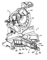
- FIG. 1 is a front perspective view of a miter saw of the present invention incorporating a miter angle fine-adjustment assembly.
- FIG. 2 is a bottom view of a table, base, and miter angle fine-adjustment assembly of the miter saw of FIG. 1 .
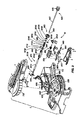
- FIG. 3 is an exploded, perspective view of the table, base, and miter angle fine-adjustment assembly of FIG. 1 .
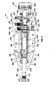
- FIG. 4 is a top view of the miter angle fine-adjustment assembly of FIG. 1 .
- FIG. 5 is a bottom view of the miter angle fine-adjustment assembly of FIG. 1 .
- FIG. 6 is a cross-sectional view of the table, base, and miter angle fine-adjustment assembly of FIG. 1 along section 6-6 in FIG. 2 , illustrating the miter angle fine-adjustment assembly disengaged from the base.
- FIG. 7 is a cross-sectional view of the table, base, and miter angle fine-adjustment assembly of FIG. 1 along section 7-7 in FIG. 2 , illustrating the miter angle fine-adjustment assembly engaged with the base.
- FIG. 8 is a cross-sectional view of the table, base, and miter angle fine-adjustment assembly of FIG. 1 along section 8-8 in FIG. 6 , illustrating the miter angle fine-adjustment assembly disengaged from the base.
- FIG. 9 is a cross-sectional view of the table, base, and miter angle fine-adjustment assembly of FIG. 1 along section 9-9 in FIG. 7 , illustrating the miter angle fine-adjustment assembly engaged with the base.
- a miter saw including a base and table assembly T is shown having a base T14 and a table T18 for supporting a work piece.
- the base and table assembly T supports a drive assembly D operable to drive a saw blade SB to cut a work piece supported on the base and table assembly T.
- the drive assembly D includes a saw unit D14 (including the saw blade SB), a motor, and a drive train operable to drive the saw blade SB.
- Such a drive assembly D is disclosed in U.S. Patent Application Serial No. 11/107,384, filed April 15, 2005 , the entire content of which is incorporated herein by reference.
- the table T18 is coupled to the base T14 for pivoting movement about a generally vertical miter axis T30.
- the drive assembly D and the saw blade SB are coupled to the table T18 for pivoting movement with the table T18 relative to the base T14 to allow the saw blade SB to perform various angled miter cuts on a work piece supported on the table T18 and/or on the base T14.
- the table and base assembly T includes a miter adjustment assembly M providing for adjustment of the angle of the saw blade SB relative to a work piece and the base T14 about the miter axis T30.
- the miter adjustment assembly M includes a coarse adjustment assembly M14 for making relatively large angular adjustments of the miter angle, and a fine adjustment assembly M18 for making accurate and/or repeatable incremental adjustments of the miter angle.
- the miter angle is indicated on a miter scale M20 coupled to the base T14 (see FIGS. 1 and 3 ).
- the coarse adjustment assembly M14 includes a miter locking assembly M22 and a miter detent assembly M26.
- the miter locking assembly M22 enables the operator to lock the table T18 in substantially any available miter angle position relative to the base T14.
- the miter locking assembly M22 includes a lock bolt M42, a knob M46 secured to one end of the lock bolt M42, and a plurality of external threads M48 formed on an end of the bolt M42 opposite the knob M46 (see FIGS. 6 and 7 ).
- the miter locking assembly M22 also includes a mounting block M44 coupling the threaded end of the bolt M42 to the table T18.
- the block M44 includes a plurality of internal threads M45 that engage the external threads M48 on the bolt M42, such that rotation of the bolt M42 relative to the block M44 also axially displaces the bolt M42 relative to the block M44.
- the bolt M42 includes an end surface M49 in facing relationship with an arcuate wall M28 on the base T14.
- the knob M46 and bolt M42 are rotated between a first or locked position, in which the end M49 of the bolt M42 engages the wall M28 to rotationally secure the table T18 relative to the base T14, and a second or unlocked position, in which the end M49 of the bolt M42 is spaced from the wall M28 to allow the table T 18 to be rotated relative to the base T 14 to change the miter angle.
- the knob M46 To unlock the table T18 from the base T14, starting from the locked position, the knob M46 need only be rotated in a counterclockwise direction to axially displace the bolt M42 relative to the block M44, thereby disengaging the end M49 of the bolt M42 from the wall M28. A user may then adjust the position of the table T18 to the left or the right to any available miter angle position. To re-lock the table T18 to the base T14, the knob M46 need only be rotated in a clockwise direction to axially displace the bolt M42 relative to the block M44, thereby engaging the end M49 of the bolt M42 and the wall M28.
- the miter detent assembly M26 provides the user with an arrangement to position the table T18 in one or more selected miter angle positions relative to the base T14 (e.g., 0 degrees; left 15 degrees, 22.5 degrees, 30 degrees and 45 degrees; right 15 degrees, 22.5 degrees, 30 degrees, 45 degrees, and 60 degrees; etc.).
- the assembly M26 includes a detent projection M50 (see FIGS. 6 and 7 ) that is selectively engageable in one or more detent notches or recesses M54, each of which corresponds to a selected miter angle position on the miter scale M20.
- the recesses M54 are provided on the base T14 (e.g., formed on the miter scale M20), and the projection M50 is supported by the table T18.
- the miter detent assembly M26 also includes a detent actuator assembly M58 for moving the projection M50 between a detent engaged position (see FIG. 6 ), in which the projection M50 engages a recess M54, and an out-of-detent or detent disengaged position (see FIG. 7 ), in which the projection M50 is not engaged with a recess M54.
- the assembly M58 includes a resilient member or leaf spring M60 having a distal end to which the projection M50 is coupled, a lever M62 pivotably coupled to the table T 18 to deflect the leaf spring M60 between the detent engaged position and the detent disengaged position, and a handle M66 coupled to the lever M62.
- the projection M50 is integrally formed with the leaf spring M60, and the leaf spring M60 is coupled to the table T18 by a plurality of fasteners (e.g., screws, bolts, etc.) via a bracket M68 (discussed in more detail below).
- the leaf spring M60 may be integrally formed with the table T18 or the bracket M68 and pivotable relative to the table T18 or the bracket M68 by a living hinge or different structure.
- the detent actuator assembly M58 includes the previously-mentioned bracket M68 (see FIG. 3 ) coupled to an interior surface of the table T18 (e.g., by a plurality of fasteners, by an adhesive, etc.).
- a middle portion of the lever M62 is pivotably coupled to the bracket M68 by a pin M69 (see FIGS. 6 and 7 ), while a tip M72 of the lever M62 engages the leaf spring M60.
- the lever M62 may be integrally formed with the bracket M68 and pivotable relative to the table T18 by a living hinge or different structure.
- a biasing member e.g., a spring M70 biases the projection M50 toward the detent engaged position.
- the spring M70 is configured as a tension spring M70, and is positioned between the bracket M68 and the lever M62 to bias the lever M62 to a position corresponding to the detent engaged position.
- the user Before operating the detent assembly M26, the user would first unlock the table T18 from the base T14, as described above with respect to the miter locking assembly M22. The user then lifts the handle M66 to lift the projection M50 out of the recess M54. The user then adjusts the position of the table T18 to the left or the right to the desired miter angle position. If the user continues to lift upwardly on the handle M66, thereby overcoming the biasing force of the spring M70, the leaf spring M60 will be maintained in a deflected condition to prevent the projection M50 from engaging any of the recesses M54 in the miter scale M20 as the table T18 is rotated relative to the base T14.
- the biasing force of the spring M70 will lift the tip M72 of the lever M62, allowing the leaf spring M60 to resume its undeflected shape, thereby causing the projection M50 to slide on the miter scale M20 and engage the next recess M54 encountered by the projection M50.
- the miter detent assembly M22 by itself, is sufficient to hold or maintain the table T18 in the selected miter angle position. However, the user may also actuate the miter locking assembly M22 to more positively lock the table T18 to the base T14.
- the fine adjustment assembly M18 generally includes inter-engaging members that are movable relative to each other to cause small incremental movement of the table T18 relative to the base T14.
- the fine adjustment assembly M18 includes a rotating member (e.g., a pinion M74) that moves along a surface (e.g., a rack M78) upon rotation of the pinion M74.
- the fine adjustment assembly M18 may utilize a pad and friction roller in place of the rack M78 and pinion M74.
- the rack M78 is supported by the base T14 rearward of the miter scale M20 and has an arcuate shape.
- the rack M78 is a separate and distinct component coupled to the base T14 by a plurality of fasteners (see also FIG. 3 ).
- the rack M78 may be integrally formed with the base T14 as a single piece.
- the pinion M74 is supported by the table T18. Rotation of the pinion M74 relative to the table T18, with the pinion M74 engaged to the rack M78, incrementally rotates the table T18 relative to the base T14 about the miter axis T30 to fine adjust the miter angle.
- the fine adjustment assembly M18 also includes a drive assembly M86 (see FIGS. 4 and 5 ) operable to deliver torque to the pinion M74 to cause the pinion M74 to rotate.
- the drive assembly M86 includes a drive gear M90, a driven gear M94, and a gear reduction assembly M98, including co-rotating gears M102, M104.
- the gear reduction assembly M98 is configured to provide a speed reduction and a resultant increase in torque between the drive gear M90 and the driven gear M94 which, ultimately, is fixed for co-rotation with the pinion M74.
- the gear reduction assembly M98 includes a speed reduction ratio of about 88:1, such that about 88 revolutions of the drive gear M90 are required to complete about a single revolution of the driven gear M94.
- the gear reduction assembly M98 may be configured to provide any of a number of different speed reduction ratios between the drive gear M90 and the driven gear M94.
- the speed reduction ratio may be in within a range of about 80:1 to about 100:1, such as at a speed reduction ratio of about 90:1.
- the pinion M74 and the gears M90, M94 are coupled to a tube assembly M118, and the co-rotating gears M102, M104 are coupled to a gear reduction tube M122.
- the drive gear M90 is carried by a drive gear tube M126
- the driven gear M94 is carried by a driven gear tube M130
- the pinion M74 is carried by a pinion tube M114.
- the pinion M74 is a separate and distinct component from the tube M114 that is fixed for co-rotation with the tube M114 (e.g., by an interference fit, adhesives, a key and keyway arrangement, etc.).
- the pinion M74 may be integrally formed with the tube M114.
- the pinion tube M114 may be axially secured to the driven gear tube M130 (e.g., by an interference or press-fit, using adhesives, etc.), such that the tubes M114, M130 are axially moveable together as a unit.
- the pinion tube M114 may be axially biased toward the driven gear tube M130 (e.g., by the interaction of the spring M70, lever M62, and slide block M140 as discussed below).
- the tubes M114, M130 are fixed to each other for co-rotation (e.g., by inter-engaging flat surfaces, a key and keyway arrangement, etc.).
- the driven gear tube 130 is axially secured to the drive gear tube M126 by a clip M134, such that the tubes M126, M130 are axially moveable together as a unit.
- the tube M126 is rotatable relative to the tube M130 due to the speed reduction imparted to the tube M130 and the driven gear M94 by the gear reduction assembly 98.
- a bushing M178 rotatably couples the tube M126 to the table T18 and maintains axial alignment of the drive gear tube M126 with the pinion tube M114.
- the bushing M178 also supports one end of the gear reduction tube M122, with the other end of the tube M122 being rotatably supported by the bracket M68 (see FIGS. 8 and 9 ), to maintain the tube M122 substantially parallel to the tubes M126. M130, M114.
- the tubes M122, M126 may be supported by the table T18 in any of a number of different ways utilizing different structure.
- the pinion M74 is movable between a driving position, in which the pinion M74 and the rack M78 are engaged (see FIG. 9 ), and a disengaged position, in which the pinion M74 is slid out of engagement with the rack M78 (see FIG. 8 ).
- the tube assembly M118 is movable relative to the gear reduction tube M122.
- the drive gear tube M126 and the gear M90 are slidable relative to the axially-fixed tube M122 and the axially-fixed gear M102.
- the driven gear tube M130 and the gear M94 are slidable relative to the axially-fixed tube M122 and the axially-fixed gear M102.
- the respective gears M90, M102 and the respective gears M94, M104 remain engaged when the pinion M74 is engaged with the rack M78 (see FIG. 9 ) and when the pinion M74 is disengaged from the rack M78 (see FIG. 8 ).
- the drive assembly M86 may be configured to disengage the respective gears M90, M102, or the respective gears M94, M104, upon the pinion M74 disengaging the rack M78.
- the tubes M114, M126, M130 are axially slidable relative to the lock bolt M42, which extends through the tubes M114, M126, M130.
- the fine adjustment assembly M18 also includes a fine adjustment actuator assembly M82 for causing rotating movement of the pinion M74 along the rack M78.
- the assembly M82 includes an actuator portion or knob M138 that is manipulated by the user to engage the drive assembly M86 and to operate the drive assembly M86 to fine adjust the miter angle.
- the knob M138 is coupled to the tube M126 by a plurality of fasteners (e.g., screws, bolts, etc.; see FIGS. 6 and 7 ).
- the knob M138 may be integrally formed with the tube M126 as a single piece.
- the knob M138 is moved axially to engage the pinion M74 and the rack M78, and then is rotated to impart torque to the pinion M74 via the tubes M126, M122, M130, M114 to incremental ly rotate the pinion M74 and subsequently the table T18.
- the actuator assembly M82 also includes a biasing member (e.g., a spring M142; see FIGS. 3 , 8 , and 9 ) positioned between a retainer M144 abutted against the bushing M178 and another retainer M144 abutted against a radially-extending flange M145 on the tube M126.
- a biasing member e.g., a spring M142; see FIGS. 3 , 8 , and 9
- the spring M142 biases the knob M138 axially away from the table T18. Because the knob M138 moves axially with the tubes M126, M130, M114 as a unit, axial displacement of the knob M138 away from the table T18 also disengages the pinion M74 from the rack M78. To engage the fine adjustment assembly M18, the knob M138 is axially displaced toward the table T18, against the bias of the spring M 142.
- the drive assembly M86 also includes a detent override assembly M146 to disengage the projection M50 from the recesses M54 and hold the projection M50 out of engagement with the recesses M54.
- the detent override assembly M 146 includes a slide block M 140 received within a channel M 136 formed in the bracket, a ramp M150 coupled to the slide block M140, and a notch M152 adjacent the ramp M150. Both the ramp M150 and the notch M152 are engageable with a portion (e.g., an upwandly-extending tab M154) of the lever M62.
- the slide block M 140 includes an aperture M156 through which the tube M114 and the lock bolt M42 extend.
- the slide block M140 rotatably supports the tube M114 and the lock bolt M42 relative to the table T18.
- the slide block M140 is axially moveable along the channel M136 with the tubes M126, M130, M114.
- a clip M158 coupled to the tube M114 is abutted with an end of the slide block M140, thereby causing the slide block M 140 and the tube M114 to be axially displaced toward the rack M78 as a unit (see FIGS. 3 , 4 , 7 , and 9 ) when the knob M138 is depressed.
- the interaction of the ramp M150 and the tab M154 causes the slide block M140 (and therefore the pinion tube M114) to be axially displaced away from the rack M78 when the knob M138 is released.
- the knob M138 is depressed toward the table T18, causing the tubes M126, M130, M114 and the slide block M140 to axially displace toward the rack M78 as a unit to engage the pinion M74 with the rack M78.
- the slide block M140 is axially displaced along the channel M136, the ramp M150 slides relative to the tab M154, causing the tip M72 of the lever M62 to pivot downwardly and downwardly-deflect the leaf spring M60 to disengage the projection M50 from the recess M54 (see FIG. 7 ).
- the tip M72 of the lever M62 Upon engagement of the tab M154 and the notch M152, the tip M72 of the lever M62 is prevented from pivoting upwardly to allow the leaf spring M60 to resume its undeflected shape to re-engage the projection M50 with one of the recesses M54. That is, the detent override assembly M146 holds the detent assembly M26 in the detent disengaged position. The user may then rotate the knob M138 to operate the drive assembly M86 to fine adjust the miter angle.
- components of the miter locking assembly M22, the actuator assembly M82, the drive assembly M86, and the detent override assembly M146 are aligned and are moveable along a common axis M162.
- the lock bolt M42 and the knob M46 are moveable along the axis M 162, relative to the table T18, to selectively lock the table T18 to the base T14.
- the knob M138 is moveable along the axis M162 to cause the pinion M74 to engage with the rack M78, and rotatable about the axis M162 to impart incremental rotation to the pinion M74.
- the tubes M126, M130 and the respective gears M90, M94 are moveable along and rotatable about the axis M162, and the tube M114 and pinion M74 are moveable along and rotatable about the axis M162.
- the slide block is moveable along the axis M162 to selectively displace the projection M50 from the miter scale M20 to prevent the projection M50 from engaging any of the recesses M54 in the miter scale M20.
Landscapes
- Life Sciences & Earth Sciences (AREA)
- Engineering & Computer Science (AREA)
- Mechanical Engineering (AREA)
- Wood Science & Technology (AREA)
- Forests & Forestry (AREA)
- Sawing (AREA)
Applications Claiming Priority (1)
| Application Number | Priority Date | Filing Date | Title |
|---|---|---|---|
| US3479808P | 2008-03-07 | 2008-03-07 |
Publications (4)
| Publication Number | Publication Date |
|---|---|
| EP2098320A2 true EP2098320A2 (de) | 2009-09-09 |
| EP2098320A3 EP2098320A3 (de) | 2011-05-25 |
| EP2098320B1 EP2098320B1 (de) | 2014-05-07 |
| EP2098320B8 EP2098320B8 (de) | 2014-08-20 |
Family
ID=40810322
Family Applications (1)
| Application Number | Title | Priority Date | Filing Date |
|---|---|---|---|
| EP20090250655 Not-in-force EP2098320B8 (de) | 2008-03-07 | 2009-03-09 | Gehrungseinstellungsvorrichtung für eine Säge |
Country Status (1)
| Country | Link |
|---|---|
| EP (1) | EP2098320B8 (de) |
Citations (1)
| Publication number | Priority date | Publication date | Assignee | Title |
|---|---|---|---|---|
| US10738405B2 (en) | 2016-03-25 | 2020-08-11 | Samsung Electronics Co., Ltd. | Washing machine |
Family Cites Families (2)
| Publication number | Priority date | Publication date | Assignee | Title |
|---|---|---|---|---|
| US5862732A (en) * | 1996-07-30 | 1999-01-26 | Milwaukee Electric Tool Corporation | Support assembly for a slide compound miter saw |
| US20050247178A1 (en) * | 2004-04-15 | 2005-11-10 | Hetcher Jason D | Power tool having an elastomeric material |
-
2009
- 2009-03-09 EP EP20090250655 patent/EP2098320B8/de not_active Not-in-force
Patent Citations (1)
| Publication number | Priority date | Publication date | Assignee | Title |
|---|---|---|---|---|
| US10738405B2 (en) | 2016-03-25 | 2020-08-11 | Samsung Electronics Co., Ltd. | Washing machine |
Also Published As
| Publication number | Publication date |
|---|---|
| EP2098320B8 (de) | 2014-08-20 |
| EP2098320A3 (de) | 2011-05-25 |
| EP2098320B1 (de) | 2014-05-07 |
Similar Documents
| Publication | Publication Date | Title |
|---|---|---|
| AU2021282494B2 (en) | Table saw | |
| US12263615B2 (en) | Circular saw | |
| US8061251B2 (en) | Miter adjustment assembly for a saw | |
| US8313094B2 (en) | Button actuated detent system | |
| CN1064574C (zh) | 带有高度或角度调节机构的锯片和电动机装载装置 | |
| AU2017200315B2 (en) | Miter saw | |
| EP2106888A2 (de) | Werkzeuglose Vorrichtung für eine Führungsschiene einer Kettensäge | |
| US20100154231A1 (en) | Rotating spindle for a reciprocating saw | |
| EP2363230B1 (de) | Schneidevorrichtung | |
| US20110041667A1 (en) | Mechanism for adjusting blade height of bench saw | |
| AU2005201541A1 (en) | Toolless adjustable jigsaw base | |
| US20050284276A1 (en) | Angular adjustment apparatus for a miter saw | |
| EP3045277B1 (de) | Gehrungssäge mit gehrungswinkelsperre | |
| EP2098320B1 (de) | Gehrungseinstellungsvorrichtung für eine Säge | |
| AU2005229769B2 (en) | Table for band saw | |
| US20110154966A1 (en) | Saw machine riving knife adjustment mechanism | |
| CN1968776A (zh) | 轨道往复锯 | |
| US9352481B2 (en) | Cutting device | |
| CN102000878A (zh) | 斜断锯 | |
| US20170106458A1 (en) | Adjustable work table | |
| US20160207217A1 (en) | Fence system for a band saw | |
| US6840148B2 (en) | Scroll sawing machine with a speed ratio varying device | |
| US20250196390A1 (en) | Miter Gauge for a Table Saw | |
| CN2486253Y (zh) | 一种截断机摆架锁紧机构 | |
| JP2007167982A (ja) | 電動切断工具 |
Legal Events
| Date | Code | Title | Description |
|---|---|---|---|
| PUAI | Public reference made under article 153(3) epc to a published international application that has entered the european phase |
Free format text: ORIGINAL CODE: 0009012 |
|
| AK | Designated contracting states |
Kind code of ref document: A2 Designated state(s): AT BE BG CH CY CZ DE DK EE ES FI FR GB GR HR HU IE IS IT LI LT LU LV MC MK MT NL NO PL PT RO SE SI SK TR |
|
| AX | Request for extension of the european patent |
Extension state: AL BA RS |
|
| PUAL | Search report despatched |
Free format text: ORIGINAL CODE: 0009013 |
|
| AK | Designated contracting states |
Kind code of ref document: A3 Designated state(s): AT BE BG CH CY CZ DE DK EE ES FI FR GB GR HR HU IE IS IT LI LT LU LV MC MK MT NL NO PL PT RO SE SI SK TR |
|
| AX | Request for extension of the european patent |
Extension state: AL BA RS |
|
| 17P | Request for examination filed |
Effective date: 20111103 |
|
| AKX | Designation fees paid |
Designated state(s): AT BE BG CH CY CZ DE DK EE ES FI FR GB GR HR HU IE IS IT LI LT LU LV MC MK MT NL NO PL PT RO SE SI SK TR |
|
| 17Q | First examination report despatched |
Effective date: 20120420 |
|
| GRAP | Despatch of communication of intention to grant a patent |
Free format text: ORIGINAL CODE: EPIDOSNIGR1 |
|
| INTG | Intention to grant announced |
Effective date: 20131126 |
|
| GRAS | Grant fee paid |
Free format text: ORIGINAL CODE: EPIDOSNIGR3 |
|
| GRAA | (expected) grant |
Free format text: ORIGINAL CODE: 0009210 |
|
| AK | Designated contracting states |
Kind code of ref document: B1 Designated state(s): AT BE BG CH CY CZ DE DK EE ES FI FR GB GR HR HU IE IS IT LI LT LU LV MC MK MT NL NO PL PT RO SE SI SK TR |
|
| REG | Reference to a national code |
Ref country code: GB Ref legal event code: FG4D |
|
| REG | Reference to a national code |
Ref country code: AT Ref legal event code: REF Ref document number: 666198 Country of ref document: AT Kind code of ref document: T Effective date: 20140515 |
|
| REG | Reference to a national code |
Ref country code: IE Ref legal event code: FG4D |
|
| REG | Reference to a national code |
Ref country code: DE Ref legal event code: R096 Ref document number: 602009023833 Country of ref document: DE Effective date: 20140618 |
|
| RIN2 | Information on inventor provided after grant (corrected) |
Inventor name: SCHNEIDER, DANIEL H. Inventor name: WEBER, MICHAEL E. Inventor name: PAPENFUSS, HAROLD L. Inventor name: HLAVAC, DAVID Inventor name: ELGER, WILLIAM A. Inventor name: WELLIVER, MICHAEL L. Inventor name: HETCHER, JASON D. Inventor name: FERNANDES, ERIC X. Inventor name: WILLER, MARK D. Inventor name: BAUER, DAVID R. Inventor name: RICHARDS, DARYL S. |
|
| REG | Reference to a national code |
Ref country code: AT Ref legal event code: MK05 Ref document number: 666198 Country of ref document: AT Kind code of ref document: T Effective date: 20140507 |
|
| REG | Reference to a national code |
Ref country code: NL Ref legal event code: VDEP Effective date: 20140507 |
|
| REG | Reference to a national code |
Ref country code: LT Ref legal event code: MG4D |
|
| PG25 | Lapsed in a contracting state [announced via postgrant information from national office to epo] |
Ref country code: NO Free format text: LAPSE BECAUSE OF FAILURE TO SUBMIT A TRANSLATION OF THE DESCRIPTION OR TO PAY THE FEE WITHIN THE PRESCRIBED TIME-LIMIT Effective date: 20140807 Ref country code: FI Free format text: LAPSE BECAUSE OF FAILURE TO SUBMIT A TRANSLATION OF THE DESCRIPTION OR TO PAY THE FEE WITHIN THE PRESCRIBED TIME-LIMIT Effective date: 20140507 Ref country code: GR Free format text: LAPSE BECAUSE OF FAILURE TO SUBMIT A TRANSLATION OF THE DESCRIPTION OR TO PAY THE FEE WITHIN THE PRESCRIBED TIME-LIMIT Effective date: 20140808 Ref country code: CY Free format text: LAPSE BECAUSE OF FAILURE TO SUBMIT A TRANSLATION OF THE DESCRIPTION OR TO PAY THE FEE WITHIN THE PRESCRIBED TIME-LIMIT Effective date: 20140507 Ref country code: LT Free format text: LAPSE BECAUSE OF FAILURE TO SUBMIT A TRANSLATION OF THE DESCRIPTION OR TO PAY THE FEE WITHIN THE PRESCRIBED TIME-LIMIT Effective date: 20140507 Ref country code: IS Free format text: LAPSE BECAUSE OF FAILURE TO SUBMIT A TRANSLATION OF THE DESCRIPTION OR TO PAY THE FEE WITHIN THE PRESCRIBED TIME-LIMIT Effective date: 20140907 |
|
| PG25 | Lapsed in a contracting state [announced via postgrant information from national office to epo] |
Ref country code: PL Free format text: LAPSE BECAUSE OF FAILURE TO SUBMIT A TRANSLATION OF THE DESCRIPTION OR TO PAY THE FEE WITHIN THE PRESCRIBED TIME-LIMIT Effective date: 20140507 Ref country code: LV Free format text: LAPSE BECAUSE OF FAILURE TO SUBMIT A TRANSLATION OF THE DESCRIPTION OR TO PAY THE FEE WITHIN THE PRESCRIBED TIME-LIMIT Effective date: 20140507 Ref country code: AT Free format text: LAPSE BECAUSE OF FAILURE TO SUBMIT A TRANSLATION OF THE DESCRIPTION OR TO PAY THE FEE WITHIN THE PRESCRIBED TIME-LIMIT Effective date: 20140507 Ref country code: SE Free format text: LAPSE BECAUSE OF FAILURE TO SUBMIT A TRANSLATION OF THE DESCRIPTION OR TO PAY THE FEE WITHIN THE PRESCRIBED TIME-LIMIT Effective date: 20140507 Ref country code: ES Free format text: LAPSE BECAUSE OF FAILURE TO SUBMIT A TRANSLATION OF THE DESCRIPTION OR TO PAY THE FEE WITHIN THE PRESCRIBED TIME-LIMIT Effective date: 20140507 Ref country code: HR Free format text: LAPSE BECAUSE OF FAILURE TO SUBMIT A TRANSLATION OF THE DESCRIPTION OR TO PAY THE FEE WITHIN THE PRESCRIBED TIME-LIMIT Effective date: 20140507 |
|
| PG25 | Lapsed in a contracting state [announced via postgrant information from national office to epo] |
Ref country code: PT Free format text: LAPSE BECAUSE OF FAILURE TO SUBMIT A TRANSLATION OF THE DESCRIPTION OR TO PAY THE FEE WITHIN THE PRESCRIBED TIME-LIMIT Effective date: 20140908 |
|
| PG25 | Lapsed in a contracting state [announced via postgrant information from national office to epo] |
Ref country code: CZ Free format text: LAPSE BECAUSE OF FAILURE TO SUBMIT A TRANSLATION OF THE DESCRIPTION OR TO PAY THE FEE WITHIN THE PRESCRIBED TIME-LIMIT Effective date: 20140507 Ref country code: EE Free format text: LAPSE BECAUSE OF FAILURE TO SUBMIT A TRANSLATION OF THE DESCRIPTION OR TO PAY THE FEE WITHIN THE PRESCRIBED TIME-LIMIT Effective date: 20140507 Ref country code: BE Free format text: LAPSE BECAUSE OF FAILURE TO SUBMIT A TRANSLATION OF THE DESCRIPTION OR TO PAY THE FEE WITHIN THE PRESCRIBED TIME-LIMIT Effective date: 20140507 Ref country code: RO Free format text: LAPSE BECAUSE OF FAILURE TO SUBMIT A TRANSLATION OF THE DESCRIPTION OR TO PAY THE FEE WITHIN THE PRESCRIBED TIME-LIMIT Effective date: 20140507 Ref country code: DK Free format text: LAPSE BECAUSE OF FAILURE TO SUBMIT A TRANSLATION OF THE DESCRIPTION OR TO PAY THE FEE WITHIN THE PRESCRIBED TIME-LIMIT Effective date: 20140507 Ref country code: SK Free format text: LAPSE BECAUSE OF FAILURE TO SUBMIT A TRANSLATION OF THE DESCRIPTION OR TO PAY THE FEE WITHIN THE PRESCRIBED TIME-LIMIT Effective date: 20140507 |
|
| REG | Reference to a national code |
Ref country code: DE Ref legal event code: R097 Ref document number: 602009023833 Country of ref document: DE |
|
| PG25 | Lapsed in a contracting state [announced via postgrant information from national office to epo] |
Ref country code: NL Free format text: LAPSE BECAUSE OF FAILURE TO SUBMIT A TRANSLATION OF THE DESCRIPTION OR TO PAY THE FEE WITHIN THE PRESCRIBED TIME-LIMIT Effective date: 20140507 |
|
| PLBE | No opposition filed within time limit |
Free format text: ORIGINAL CODE: 0009261 |
|
| STAA | Information on the status of an ep patent application or granted ep patent |
Free format text: STATUS: NO OPPOSITION FILED WITHIN TIME LIMIT |
|
| 26N | No opposition filed |
Effective date: 20150210 |
|
| PG25 | Lapsed in a contracting state [announced via postgrant information from national office to epo] |
Ref country code: IT Free format text: LAPSE BECAUSE OF FAILURE TO SUBMIT A TRANSLATION OF THE DESCRIPTION OR TO PAY THE FEE WITHIN THE PRESCRIBED TIME-LIMIT Effective date: 20140507 |
|
| REG | Reference to a national code |
Ref country code: DE Ref legal event code: R097 Ref document number: 602009023833 Country of ref document: DE Effective date: 20150210 |
|
| PG25 | Lapsed in a contracting state [announced via postgrant information from national office to epo] |
Ref country code: SI Free format text: LAPSE BECAUSE OF FAILURE TO SUBMIT A TRANSLATION OF THE DESCRIPTION OR TO PAY THE FEE WITHIN THE PRESCRIBED TIME-LIMIT Effective date: 20140507 |
|
| PG25 | Lapsed in a contracting state [announced via postgrant information from national office to epo] |
Ref country code: LU Free format text: LAPSE BECAUSE OF FAILURE TO SUBMIT A TRANSLATION OF THE DESCRIPTION OR TO PAY THE FEE WITHIN THE PRESCRIBED TIME-LIMIT Effective date: 20150309 Ref country code: MC Free format text: LAPSE BECAUSE OF FAILURE TO SUBMIT A TRANSLATION OF THE DESCRIPTION OR TO PAY THE FEE WITHIN THE PRESCRIBED TIME-LIMIT Effective date: 20140507 |
|
| REG | Reference to a national code |
Ref country code: CH Ref legal event code: PL |
|
| REG | Reference to a national code |
Ref country code: FR Ref legal event code: ST Effective date: 20151130 |
|
| REG | Reference to a national code |
Ref country code: IE Ref legal event code: MM4A |
|
| PG25 | Lapsed in a contracting state [announced via postgrant information from national office to epo] |
Ref country code: CH Free format text: LAPSE BECAUSE OF NON-PAYMENT OF DUE FEES Effective date: 20150331 Ref country code: LI Free format text: LAPSE BECAUSE OF NON-PAYMENT OF DUE FEES Effective date: 20150331 Ref country code: IE Free format text: LAPSE BECAUSE OF NON-PAYMENT OF DUE FEES Effective date: 20150309 |
|
| PG25 | Lapsed in a contracting state [announced via postgrant information from national office to epo] |
Ref country code: FR Free format text: LAPSE BECAUSE OF NON-PAYMENT OF DUE FEES Effective date: 20150331 |
|
| PG25 | Lapsed in a contracting state [announced via postgrant information from national office to epo] |
Ref country code: MT Free format text: LAPSE BECAUSE OF FAILURE TO SUBMIT A TRANSLATION OF THE DESCRIPTION OR TO PAY THE FEE WITHIN THE PRESCRIBED TIME-LIMIT Effective date: 20140507 |
|
| PG25 | Lapsed in a contracting state [announced via postgrant information from national office to epo] |
Ref country code: BG Free format text: LAPSE BECAUSE OF FAILURE TO SUBMIT A TRANSLATION OF THE DESCRIPTION OR TO PAY THE FEE WITHIN THE PRESCRIBED TIME-LIMIT Effective date: 20140507 Ref country code: HU Free format text: LAPSE BECAUSE OF FAILURE TO SUBMIT A TRANSLATION OF THE DESCRIPTION OR TO PAY THE FEE WITHIN THE PRESCRIBED TIME-LIMIT; INVALID AB INITIO Effective date: 20090309 |
|
| PG25 | Lapsed in a contracting state [announced via postgrant information from national office to epo] |
Ref country code: TR Free format text: LAPSE BECAUSE OF FAILURE TO SUBMIT A TRANSLATION OF THE DESCRIPTION OR TO PAY THE FEE WITHIN THE PRESCRIBED TIME-LIMIT Effective date: 20140507 |
|
| PG25 | Lapsed in a contracting state [announced via postgrant information from national office to epo] |
Ref country code: MK Free format text: LAPSE BECAUSE OF FAILURE TO SUBMIT A TRANSLATION OF THE DESCRIPTION OR TO PAY THE FEE WITHIN THE PRESCRIBED TIME-LIMIT Effective date: 20140507 |
|
| PGFP | Annual fee paid to national office [announced via postgrant information from national office to epo] |
Ref country code: GB Payment date: 20230327 Year of fee payment: 15 Ref country code: DE Payment date: 20230329 Year of fee payment: 15 |
|
| REG | Reference to a national code |
Ref country code: DE Ref legal event code: R119 Ref document number: 602009023833 Country of ref document: DE |
|
| GBPC | Gb: european patent ceased through non-payment of renewal fee |
Effective date: 20240309 |
|
| PG25 | Lapsed in a contracting state [announced via postgrant information from national office to epo] |
Ref country code: DE Free format text: LAPSE BECAUSE OF NON-PAYMENT OF DUE FEES Effective date: 20241001 |
|
| PG25 | Lapsed in a contracting state [announced via postgrant information from national office to epo] |
Ref country code: GB Free format text: LAPSE BECAUSE OF NON-PAYMENT OF DUE FEES Effective date: 20240309 |
|
| PG25 | Lapsed in a contracting state [announced via postgrant information from national office to epo] |
Ref country code: GB Free format text: LAPSE BECAUSE OF NON-PAYMENT OF DUE FEES Effective date: 20240309 Ref country code: DE Free format text: LAPSE BECAUSE OF NON-PAYMENT OF DUE FEES Effective date: 20241001 |