EP2098274A1 - Sealing material for a honeycomb structured body, honeycomb structured body and method for manufacturing the honeycomb structured body - Google Patents
Sealing material for a honeycomb structured body, honeycomb structured body and method for manufacturing the honeycomb structured body Download PDFInfo
- Publication number
- EP2098274A1 EP2098274A1 EP08165491A EP08165491A EP2098274A1 EP 2098274 A1 EP2098274 A1 EP 2098274A1 EP 08165491 A EP08165491 A EP 08165491A EP 08165491 A EP08165491 A EP 08165491A EP 2098274 A1 EP2098274 A1 EP 2098274A1
- Authority
- EP
- European Patent Office
- Prior art keywords
- structured body
- honeycomb structured
- sealing material
- honeycomb
- fired bodies
- Prior art date
- Legal status (The legal status is an assumption and is not a legal conclusion. Google has not performed a legal analysis and makes no representation as to the accuracy of the status listed.)
- Granted
Links
Images





Classifications
-
- C—CHEMISTRY; METALLURGY
- C09—DYES; PAINTS; POLISHES; NATURAL RESINS; ADHESIVES; COMPOSITIONS NOT OTHERWISE PROVIDED FOR; APPLICATIONS OF MATERIALS NOT OTHERWISE PROVIDED FOR
- C09K—MATERIALS FOR MISCELLANEOUS APPLICATIONS, NOT PROVIDED FOR ELSEWHERE
- C09K3/00—Materials not provided for elsewhere
- C09K3/10—Materials in mouldable or extrudable form for sealing or packing joints or covers
-
- C—CHEMISTRY; METALLURGY
- C04—CEMENTS; CONCRETE; ARTIFICIAL STONE; CERAMICS; REFRACTORIES
- C04B—LIME, MAGNESIA; SLAG; CEMENTS; COMPOSITIONS THEREOF, e.g. MORTARS, CONCRETE OR LIKE BUILDING MATERIALS; ARTIFICIAL STONE; CERAMICS; REFRACTORIES; TREATMENT OF NATURAL STONE
- C04B35/00—Shaped ceramic products characterised by their composition; Ceramics compositions; Processing powders of inorganic compounds preparatory to the manufacturing of ceramic products
- C04B35/622—Forming processes; Processing powders of inorganic compounds preparatory to the manufacturing of ceramic products
- C04B35/626—Preparing or treating the powders individually or as batches ; preparing or treating macroscopic reinforcing agents for ceramic products, e.g. fibres; mechanical aspects section B
- C04B35/63—Preparing or treating the powders individually or as batches ; preparing or treating macroscopic reinforcing agents for ceramic products, e.g. fibres; mechanical aspects section B using additives specially adapted for forming the products, e.g.. binder binders
- C04B35/632—Organic additives
-
- B—PERFORMING OPERATIONS; TRANSPORTING
- B82—NANOTECHNOLOGY
- B82Y—SPECIFIC USES OR APPLICATIONS OF NANOSTRUCTURES; MEASUREMENT OR ANALYSIS OF NANOSTRUCTURES; MANUFACTURE OR TREATMENT OF NANOSTRUCTURES
- B82Y30/00—Nanotechnology for materials or surface science, e.g. nanocomposites
-
- B—PERFORMING OPERATIONS; TRANSPORTING
- B01—PHYSICAL OR CHEMICAL PROCESSES OR APPARATUS IN GENERAL
- B01J—CHEMICAL OR PHYSICAL PROCESSES, e.g. CATALYSIS OR COLLOID CHEMISTRY; THEIR RELEVANT APPARATUS
- B01J35/00—Catalysts, in general, characterised by their form or physical properties
- B01J35/50—Catalysts, in general, characterised by their form or physical properties characterised by their shape or configuration
- B01J35/56—Foraminous structures having flow-through passages or channels, e.g. grids or three-dimensional [3D] monoliths
- B01J35/57—Honeycombs
-
- C—CHEMISTRY; METALLURGY
- C04—CEMENTS; CONCRETE; ARTIFICIAL STONE; CERAMICS; REFRACTORIES
- C04B—LIME, MAGNESIA; SLAG; CEMENTS; COMPOSITIONS THEREOF, e.g. MORTARS, CONCRETE OR LIKE BUILDING MATERIALS; ARTIFICIAL STONE; CERAMICS; REFRACTORIES; TREATMENT OF NATURAL STONE
- C04B35/00—Shaped ceramic products characterised by their composition; Ceramics compositions; Processing powders of inorganic compounds preparatory to the manufacturing of ceramic products
- C04B35/515—Shaped ceramic products characterised by their composition; Ceramics compositions; Processing powders of inorganic compounds preparatory to the manufacturing of ceramic products based on non-oxide ceramics
- C04B35/56—Shaped ceramic products characterised by their composition; Ceramics compositions; Processing powders of inorganic compounds preparatory to the manufacturing of ceramic products based on non-oxide ceramics based on carbides or oxycarbides
- C04B35/565—Shaped ceramic products characterised by their composition; Ceramics compositions; Processing powders of inorganic compounds preparatory to the manufacturing of ceramic products based on non-oxide ceramics based on carbides or oxycarbides based on silicon carbide
-
- C—CHEMISTRY; METALLURGY
- C04—CEMENTS; CONCRETE; ARTIFICIAL STONE; CERAMICS; REFRACTORIES
- C04B—LIME, MAGNESIA; SLAG; CEMENTS; COMPOSITIONS THEREOF, e.g. MORTARS, CONCRETE OR LIKE BUILDING MATERIALS; ARTIFICIAL STONE; CERAMICS; REFRACTORIES; TREATMENT OF NATURAL STONE
- C04B35/00—Shaped ceramic products characterised by their composition; Ceramics compositions; Processing powders of inorganic compounds preparatory to the manufacturing of ceramic products
- C04B35/622—Forming processes; Processing powders of inorganic compounds preparatory to the manufacturing of ceramic products
- C04B35/62227—Forming processes; Processing powders of inorganic compounds preparatory to the manufacturing of ceramic products obtaining fibres
- C04B35/62231—Forming processes; Processing powders of inorganic compounds preparatory to the manufacturing of ceramic products obtaining fibres based on oxide ceramics
- C04B35/6224—Fibres based on silica
-
- C—CHEMISTRY; METALLURGY
- C04—CEMENTS; CONCRETE; ARTIFICIAL STONE; CERAMICS; REFRACTORIES
- C04B—LIME, MAGNESIA; SLAG; CEMENTS; COMPOSITIONS THEREOF, e.g. MORTARS, CONCRETE OR LIKE BUILDING MATERIALS; ARTIFICIAL STONE; CERAMICS; REFRACTORIES; TREATMENT OF NATURAL STONE
- C04B35/00—Shaped ceramic products characterised by their composition; Ceramics compositions; Processing powders of inorganic compounds preparatory to the manufacturing of ceramic products
- C04B35/622—Forming processes; Processing powders of inorganic compounds preparatory to the manufacturing of ceramic products
- C04B35/626—Preparing or treating the powders individually or as batches ; preparing or treating macroscopic reinforcing agents for ceramic products, e.g. fibres; mechanical aspects section B
- C04B35/63—Preparing or treating the powders individually or as batches ; preparing or treating macroscopic reinforcing agents for ceramic products, e.g. fibres; mechanical aspects section B using additives specially adapted for forming the products, e.g.. binder binders
- C04B35/6303—Inorganic additives
- C04B35/6316—Binders based on silicon compounds
-
- C—CHEMISTRY; METALLURGY
- C04—CEMENTS; CONCRETE; ARTIFICIAL STONE; CERAMICS; REFRACTORIES
- C04B—LIME, MAGNESIA; SLAG; CEMENTS; COMPOSITIONS THEREOF, e.g. MORTARS, CONCRETE OR LIKE BUILDING MATERIALS; ARTIFICIAL STONE; CERAMICS; REFRACTORIES; TREATMENT OF NATURAL STONE
- C04B35/00—Shaped ceramic products characterised by their composition; Ceramics compositions; Processing powders of inorganic compounds preparatory to the manufacturing of ceramic products
- C04B35/71—Ceramic products containing macroscopic reinforcing agents
- C04B35/78—Ceramic products containing macroscopic reinforcing agents containing non-metallic materials
- C04B35/80—Fibres, filaments, whiskers, platelets, or the like
-
- C—CHEMISTRY; METALLURGY
- C04—CEMENTS; CONCRETE; ARTIFICIAL STONE; CERAMICS; REFRACTORIES
- C04B—LIME, MAGNESIA; SLAG; CEMENTS; COMPOSITIONS THEREOF, e.g. MORTARS, CONCRETE OR LIKE BUILDING MATERIALS; ARTIFICIAL STONE; CERAMICS; REFRACTORIES; TREATMENT OF NATURAL STONE
- C04B38/00—Porous mortars, concrete, artificial stone or ceramic ware; Preparation thereof
- C04B38/0006—Honeycomb structures
- C04B38/0012—Honeycomb structures characterised by the material used for sealing or plugging (some of) the channels of the honeycombs
-
- C—CHEMISTRY; METALLURGY
- C04—CEMENTS; CONCRETE; ARTIFICIAL STONE; CERAMICS; REFRACTORIES
- C04B—LIME, MAGNESIA; SLAG; CEMENTS; COMPOSITIONS THEREOF, e.g. MORTARS, CONCRETE OR LIKE BUILDING MATERIALS; ARTIFICIAL STONE; CERAMICS; REFRACTORIES; TREATMENT OF NATURAL STONE
- C04B41/00—After-treatment of mortars, concrete, artificial stone or ceramics; Treatment of natural stone
- C04B41/009—After-treatment of mortars, concrete, artificial stone or ceramics; Treatment of natural stone characterised by the material treated
-
- C—CHEMISTRY; METALLURGY
- C04—CEMENTS; CONCRETE; ARTIFICIAL STONE; CERAMICS; REFRACTORIES
- C04B—LIME, MAGNESIA; SLAG; CEMENTS; COMPOSITIONS THEREOF, e.g. MORTARS, CONCRETE OR LIKE BUILDING MATERIALS; ARTIFICIAL STONE; CERAMICS; REFRACTORIES; TREATMENT OF NATURAL STONE
- C04B41/00—After-treatment of mortars, concrete, artificial stone or ceramics; Treatment of natural stone
- C04B41/45—Coating or impregnating, e.g. injection in masonry, partial coating of green or fired ceramics, organic coating compositions for adhering together two concrete elements
- C04B41/50—Coating or impregnating, e.g. injection in masonry, partial coating of green or fired ceramics, organic coating compositions for adhering together two concrete elements with inorganic materials
- C04B41/5076—Coating or impregnating, e.g. injection in masonry, partial coating of green or fired ceramics, organic coating compositions for adhering together two concrete elements with inorganic materials with masses bonded by inorganic cements
- C04B41/5089—Silica sols, alkyl, ammonium or alkali metal silicate cements
-
- C—CHEMISTRY; METALLURGY
- C04—CEMENTS; CONCRETE; ARTIFICIAL STONE; CERAMICS; REFRACTORIES
- C04B—LIME, MAGNESIA; SLAG; CEMENTS; COMPOSITIONS THEREOF, e.g. MORTARS, CONCRETE OR LIKE BUILDING MATERIALS; ARTIFICIAL STONE; CERAMICS; REFRACTORIES; TREATMENT OF NATURAL STONE
- C04B41/00—After-treatment of mortars, concrete, artificial stone or ceramics; Treatment of natural stone
- C04B41/80—After-treatment of mortars, concrete, artificial stone or ceramics; Treatment of natural stone of only ceramics
- C04B41/81—Coating or impregnation
- C04B41/85—Coating or impregnation with inorganic materials
-
- B—PERFORMING OPERATIONS; TRANSPORTING
- B01—PHYSICAL OR CHEMICAL PROCESSES OR APPARATUS IN GENERAL
- B01J—CHEMICAL OR PHYSICAL PROCESSES, e.g. CATALYSIS OR COLLOID CHEMISTRY; THEIR RELEVANT APPARATUS
- B01J23/00—Catalysts comprising metals or metal oxides or hydroxides, not provided for in group B01J21/00
- B01J23/38—Catalysts comprising metals or metal oxides or hydroxides, not provided for in group B01J21/00 of noble metals
- B01J23/40—Catalysts comprising metals or metal oxides or hydroxides, not provided for in group B01J21/00 of noble metals of the platinum group metals
-
- B—PERFORMING OPERATIONS; TRANSPORTING
- B01—PHYSICAL OR CHEMICAL PROCESSES OR APPARATUS IN GENERAL
- B01J—CHEMICAL OR PHYSICAL PROCESSES, e.g. CATALYSIS OR COLLOID CHEMISTRY; THEIR RELEVANT APPARATUS
- B01J23/00—Catalysts comprising metals or metal oxides or hydroxides, not provided for in group B01J21/00
- B01J23/38—Catalysts comprising metals or metal oxides or hydroxides, not provided for in group B01J21/00 of noble metals
- B01J23/54—Catalysts comprising metals or metal oxides or hydroxides, not provided for in group B01J21/00 of noble metals combined with metals, oxides or hydroxides provided for in groups B01J23/02 - B01J23/36
- B01J23/56—Platinum group metals
- B01J23/58—Platinum group metals with alkali- or alkaline earth metals
-
- C—CHEMISTRY; METALLURGY
- C04—CEMENTS; CONCRETE; ARTIFICIAL STONE; CERAMICS; REFRACTORIES
- C04B—LIME, MAGNESIA; SLAG; CEMENTS; COMPOSITIONS THEREOF, e.g. MORTARS, CONCRETE OR LIKE BUILDING MATERIALS; ARTIFICIAL STONE; CERAMICS; REFRACTORIES; TREATMENT OF NATURAL STONE
- C04B2111/00—Mortars, concrete or artificial stone or mixtures to prepare them, characterised by specific function, property or use
- C04B2111/00474—Uses not provided for elsewhere in C04B2111/00
- C04B2111/00793—Uses not provided for elsewhere in C04B2111/00 as filters or diaphragms
-
- C—CHEMISTRY; METALLURGY
- C04—CEMENTS; CONCRETE; ARTIFICIAL STONE; CERAMICS; REFRACTORIES
- C04B—LIME, MAGNESIA; SLAG; CEMENTS; COMPOSITIONS THEREOF, e.g. MORTARS, CONCRETE OR LIKE BUILDING MATERIALS; ARTIFICIAL STONE; CERAMICS; REFRACTORIES; TREATMENT OF NATURAL STONE
- C04B2111/00—Mortars, concrete or artificial stone or mixtures to prepare them, characterised by specific function, property or use
- C04B2111/00474—Uses not provided for elsewhere in C04B2111/00
- C04B2111/0081—Uses not provided for elsewhere in C04B2111/00 as catalysts or catalyst carriers
-
- C—CHEMISTRY; METALLURGY
- C04—CEMENTS; CONCRETE; ARTIFICIAL STONE; CERAMICS; REFRACTORIES
- C04B—LIME, MAGNESIA; SLAG; CEMENTS; COMPOSITIONS THEREOF, e.g. MORTARS, CONCRETE OR LIKE BUILDING MATERIALS; ARTIFICIAL STONE; CERAMICS; REFRACTORIES; TREATMENT OF NATURAL STONE
- C04B2235/00—Aspects relating to ceramic starting mixtures or sintered ceramic products
- C04B2235/02—Composition of constituents of the starting material or of secondary phases of the final product
- C04B2235/30—Constituents and secondary phases not being of a fibrous nature
- C04B2235/34—Non-metal oxides, non-metal mixed oxides, or salts thereof that form the non-metal oxides upon heating, e.g. carbonates, nitrates, (oxy)hydroxides, chlorides
- C04B2235/3418—Silicon oxide, silicic acids or oxide forming salts thereof, e.g. silica sol, fused silica, silica fume, cristobalite, quartz or flint
-
- C—CHEMISTRY; METALLURGY
- C04—CEMENTS; CONCRETE; ARTIFICIAL STONE; CERAMICS; REFRACTORIES
- C04B—LIME, MAGNESIA; SLAG; CEMENTS; COMPOSITIONS THEREOF, e.g. MORTARS, CONCRETE OR LIKE BUILDING MATERIALS; ARTIFICIAL STONE; CERAMICS; REFRACTORIES; TREATMENT OF NATURAL STONE
- C04B2235/00—Aspects relating to ceramic starting mixtures or sintered ceramic products
- C04B2235/02—Composition of constituents of the starting material or of secondary phases of the final product
- C04B2235/50—Constituents or additives of the starting mixture chosen for their shape or used because of their shape or their physical appearance
- C04B2235/52—Constituents or additives characterised by their shapes
- C04B2235/5208—Fibers
- C04B2235/5216—Inorganic
- C04B2235/522—Oxidic
- C04B2235/5232—Silica or silicates other than aluminosilicates, e.g. quartz
-
- C—CHEMISTRY; METALLURGY
- C04—CEMENTS; CONCRETE; ARTIFICIAL STONE; CERAMICS; REFRACTORIES
- C04B—LIME, MAGNESIA; SLAG; CEMENTS; COMPOSITIONS THEREOF, e.g. MORTARS, CONCRETE OR LIKE BUILDING MATERIALS; ARTIFICIAL STONE; CERAMICS; REFRACTORIES; TREATMENT OF NATURAL STONE
- C04B2235/00—Aspects relating to ceramic starting mixtures or sintered ceramic products
- C04B2235/02—Composition of constituents of the starting material or of secondary phases of the final product
- C04B2235/50—Constituents or additives of the starting mixture chosen for their shape or used because of their shape or their physical appearance
- C04B2235/54—Particle size related information
- C04B2235/5418—Particle size related information expressed by the size of the particles or aggregates thereof
- C04B2235/5436—Particle size related information expressed by the size of the particles or aggregates thereof micrometer sized, i.e. from 1 to 100 micron
-
- C—CHEMISTRY; METALLURGY
- C04—CEMENTS; CONCRETE; ARTIFICIAL STONE; CERAMICS; REFRACTORIES
- C04B—LIME, MAGNESIA; SLAG; CEMENTS; COMPOSITIONS THEREOF, e.g. MORTARS, CONCRETE OR LIKE BUILDING MATERIALS; ARTIFICIAL STONE; CERAMICS; REFRACTORIES; TREATMENT OF NATURAL STONE
- C04B2235/00—Aspects relating to ceramic starting mixtures or sintered ceramic products
- C04B2235/02—Composition of constituents of the starting material or of secondary phases of the final product
- C04B2235/50—Constituents or additives of the starting mixture chosen for their shape or used because of their shape or their physical appearance
- C04B2235/54—Particle size related information
- C04B2235/5418—Particle size related information expressed by the size of the particles or aggregates thereof
- C04B2235/5445—Particle size related information expressed by the size of the particles or aggregates thereof submicron sized, i.e. from 0,1 to 1 micron
-
- C—CHEMISTRY; METALLURGY
- C04—CEMENTS; CONCRETE; ARTIFICIAL STONE; CERAMICS; REFRACTORIES
- C04B—LIME, MAGNESIA; SLAG; CEMENTS; COMPOSITIONS THEREOF, e.g. MORTARS, CONCRETE OR LIKE BUILDING MATERIALS; ARTIFICIAL STONE; CERAMICS; REFRACTORIES; TREATMENT OF NATURAL STONE
- C04B2235/00—Aspects relating to ceramic starting mixtures or sintered ceramic products
- C04B2235/02—Composition of constituents of the starting material or of secondary phases of the final product
- C04B2235/50—Constituents or additives of the starting mixture chosen for their shape or used because of their shape or their physical appearance
- C04B2235/54—Particle size related information
- C04B2235/5418—Particle size related information expressed by the size of the particles or aggregates thereof
- C04B2235/5454—Particle size related information expressed by the size of the particles or aggregates thereof nanometer sized, i.e. below 100 nm
-
- C—CHEMISTRY; METALLURGY
- C04—CEMENTS; CONCRETE; ARTIFICIAL STONE; CERAMICS; REFRACTORIES
- C04B—LIME, MAGNESIA; SLAG; CEMENTS; COMPOSITIONS THEREOF, e.g. MORTARS, CONCRETE OR LIKE BUILDING MATERIALS; ARTIFICIAL STONE; CERAMICS; REFRACTORIES; TREATMENT OF NATURAL STONE
- C04B2235/00—Aspects relating to ceramic starting mixtures or sintered ceramic products
- C04B2235/02—Composition of constituents of the starting material or of secondary phases of the final product
- C04B2235/50—Constituents or additives of the starting mixture chosen for their shape or used because of their shape or their physical appearance
- C04B2235/54—Particle size related information
- C04B2235/5463—Particle size distributions
- C04B2235/5472—Bimodal, multi-modal or multi-fraction
-
- Y—GENERAL TAGGING OF NEW TECHNOLOGICAL DEVELOPMENTS; GENERAL TAGGING OF CROSS-SECTIONAL TECHNOLOGIES SPANNING OVER SEVERAL SECTIONS OF THE IPC; TECHNICAL SUBJECTS COVERED BY FORMER USPC CROSS-REFERENCE ART COLLECTIONS [XRACs] AND DIGESTS
- Y10—TECHNICAL SUBJECTS COVERED BY FORMER USPC
- Y10T—TECHNICAL SUBJECTS COVERED BY FORMER US CLASSIFICATION
- Y10T156/00—Adhesive bonding and miscellaneous chemical manufacture
- Y10T156/10—Methods of surface bonding and/or assembly therefor
-
- Y—GENERAL TAGGING OF NEW TECHNOLOGICAL DEVELOPMENTS; GENERAL TAGGING OF CROSS-SECTIONAL TECHNOLOGIES SPANNING OVER SEVERAL SECTIONS OF THE IPC; TECHNICAL SUBJECTS COVERED BY FORMER USPC CROSS-REFERENCE ART COLLECTIONS [XRACs] AND DIGESTS
- Y10—TECHNICAL SUBJECTS COVERED BY FORMER USPC
- Y10T—TECHNICAL SUBJECTS COVERED BY FORMER US CLASSIFICATION
- Y10T428/00—Stock material or miscellaneous articles
- Y10T428/24—Structurally defined web or sheet [e.g., overall dimension, etc.]
- Y10T428/24149—Honeycomb-like
-
- Y—GENERAL TAGGING OF NEW TECHNOLOGICAL DEVELOPMENTS; GENERAL TAGGING OF CROSS-SECTIONAL TECHNOLOGIES SPANNING OVER SEVERAL SECTIONS OF THE IPC; TECHNICAL SUBJECTS COVERED BY FORMER USPC CROSS-REFERENCE ART COLLECTIONS [XRACs] AND DIGESTS
- Y10—TECHNICAL SUBJECTS COVERED BY FORMER USPC
- Y10T—TECHNICAL SUBJECTS COVERED BY FORMER US CLASSIFICATION
- Y10T428/00—Stock material or miscellaneous articles
- Y10T428/29—Coated or structually defined flake, particle, cell, strand, strand portion, rod, filament, macroscopic fiber or mass thereof
- Y10T428/2913—Rod, strand, filament or fiber
- Y10T428/298—Physical dimension
-
- Y—GENERAL TAGGING OF NEW TECHNOLOGICAL DEVELOPMENTS; GENERAL TAGGING OF CROSS-SECTIONAL TECHNOLOGIES SPANNING OVER SEVERAL SECTIONS OF THE IPC; TECHNICAL SUBJECTS COVERED BY FORMER USPC CROSS-REFERENCE ART COLLECTIONS [XRACs] AND DIGESTS
- Y10—TECHNICAL SUBJECTS COVERED BY FORMER USPC
- Y10T—TECHNICAL SUBJECTS COVERED BY FORMER US CLASSIFICATION
- Y10T428/00—Stock material or miscellaneous articles
- Y10T428/29—Coated or structually defined flake, particle, cell, strand, strand portion, rod, filament, macroscopic fiber or mass thereof
- Y10T428/2982—Particulate matter [e.g., sphere, flake, etc.]
Definitions
- the present invention relates to a sealing material for a honeycomb structured body, a honeycomb structured body and a method for manufacturing a honeycomb structured body.
- inorganic fibers In a honeycomb structured body used as a filter for removing particulates and the like from exhaust gases discharged from an internal combustion engine such as a diesel engine, or as a catalyst supporting carrier for removing toxic components such as HC and CO from the exhaust gases, inorganic fibers have been used as materials for various constituent members. Specific examples thereof includes a sealing material containing inorganic fibers such as a sealing material (adhesive) for combining a plurality of honeycomb fired bodies to form a ceramic block and a sealing material (peripheral sealing material) to be formed on the periphery of a ceramic block.
- a sealing material containing inorganic fibers such as a sealing material (adhesive) for combining a plurality of honeycomb fired bodies to form a ceramic block and a sealing material (peripheral sealing material) to be formed on the periphery of a ceramic block.
- the inorganic fibers used in the sealing material are desirably highly safe to the human body.
- Patent Document 1 has described a sealing material containing, as inorganic fibers, at least one kind selected from the group consisting of an alkali metal compound, an alkaline earth metal compound and a boron compound.
- Patent Document 1 The compound included in the inorganic fibers, described in Patent Document 1, are so-called biosoluble fibers.
- the biosoluble fibers are soluble in physiological saline solution. Therefore, even when taken into the human body, the biosoluble fibers are dissolved and discharged out of the body, and are subsequently considered to be highly safe to the human body.
- Patent Document 1 WO05/110578 Al
- the above-mentioned sealing material is prepared in the form of a paste by mixing an inorganic binder, an organic binder, inorganic particles, water and the like with the inorganic fibers, because the sealing material is applied to a ceramic block or a honeycomb fired body when used.
- the sealing material is prepared by using the biosoluble fibers as the inorganic fibers, and an oxide sol as the inorganic binder, aggregation or gelation tends to occur in the sealing material as the time elapses after preparation of the sealing material, leading to low flowability and a high viscosity of the paste.
- a phenomenon such as aggregation or gelation occurs in the sealing material, a problem arises in which applying of the sealing material to the ceramic block or the like becomes difficult.
- the present invention has been devised to solve these problems, and its object is to provide a sealing material for a honeycomb structured body containing well biosoluble inorganic fibers and having superior coating properties to a ceramic block or the like even a long time after preparation of the paste. Moreover, another object is to provide a honeycomb structured body manufactured by using the above-mentioned sealing material for a honeycomb structured body and also to provide a method for manufacturing such the above-mentioned honeycomb structured body.
- the inventors of the present invention have intensively examined causes for aggregation or gelation in the sealing material. As a result, the inventors have found that, when the paste is alkaline, in particular, has a pH exceeding 6, gelation in the sealing material tends to occur due to gelation of the oxide sol.
- gelation refers to a phenomenon of aggregation of solid components dispersed in a sol, which is caused by a change in the pH or the like and causes an increase in the viscosity.
- electrical double layers are formed on the surfaces of the inorganic particles and the oxide sol contained in the sealing material.
- the electrical double layers are considered to allow the inorganic particles and the oxide sol to stably exist dispersed.
- polyvalent metal ions Ca 2+ , Mg 2+
- the pH of the paste is considered to give influences to the reaction rate between the polyvalent metal ions and the oxide sol. Under high pH conditions, the reaction rate is faster so that gelation of the sealing material easily progresses.
- the inventors of the present invention have also found that, when the paste is acidic, in particular, has a pH of less than 4, the inorganic particles in the paste tend to aggregate.
- the inventors of the present invention have found that it is possible to provide a sealing material for a honeycomb structured body having coating properties to the ceramic block or the like even a long time after preparation of the paste by controlling the pH of the sealing material for a honeycomb structured body in a suitable range, and consequently have completed the present invention.
- the sealing material for a honeycomb structured body according to claim 1 comprises inorganic fibers, oxide sol and inorganic particles, wherein the inorganic fibers include at least one kind selected from the group consisting of an alkali metal compound, an alkaline earth metal compound and a boron compound, and a pH of the sealing material for a honeycomb structured body is 4 to 6.
- the inorganic fibers contained in the sealing material for a honeycomb structured body according to claim 1 includes at least one kind selected from the group consisting of an alkali metal compound, an alkaline earth metal compound and a boron compound. Since these compounds are so-called biosoluble fibers, it is possible to provide a sealing material for a honeycomb structured body that is highly safe to the human body.
- the pH of the sealing material for a honeycomb structured body is 4 or more, inorganic particles are not allowed to aggregate after preparation of the paste. Moreover, since the pH of the sealing material for a honeycomb structured body is 6 or less, the sealing material is not allowed to gelate after preparation of the paste. For these reasons, it is possible to prevent a deterioration in the flowability of the paste and an increase in the viscosity thereof even a long time after preparation of the paste. Therefore, it is possible to provide a sealing material for a honeycomb structured body that is has superior coating properties to the ceramic block or the like even a long time after preparation of the paste.
- an acidic solution is mixed with an alkaline mixture containing an alkaline oxide sol as the oxide sol, the inorganic fibers and the inorganic particles.
- a pH of the acidic solution is 1 to 3.
- the acidic solution is a lactic acid aqueous solution.
- an average particle diameter of the oxide sol is 5 to 30 nm.
- the oxide sol having an average particle diameter of 5 to 30 nm when the sealing material for a honeycomb structured body is used as an adhesive for bonding honeycomb fired bodies to one another, it is possible to increase the adhesive strength between the honeycomb fired bodies.
- the oxide sol is silica sol.
- the honeycomb structured body according to claim 7 comprises a ceramic block including one or a plurality of pillar-shaped honeycomb fired bodies each having a large number of cells longitudinally placed in parallel with one another with a cell wall interposed therebetween; and a peripheral sealing material layer formed on a peripheral face of the ceramic block, wherein the peripheral sealing material layer is formed by drying and solidifying a sealing material for a honeycomb structured body containing inorganic fibers, oxide sol and inorganic particles and having a pH of 4 to 6, the inorganic fibers selected from the group consisting of an alkali metal compound, an alkaline earth metal compound and a boron compound.
- the inorganic fibers contained in the sealing material for a honeycomb structured body according to claim 7 includes at least one kind selected from the group consisting of an alkali metal compound, an alkaline earth metal compound and a boron compound, and the inorganic fibers including the above-mentioned compound are also contained in the peripheral sealing material layer. Since these compounds are so-called biosoluble fibers, it is possible to manufacture a honeycomb structured body that is highly safe to the human body.
- the ceramic block comprises the plurality of the honeycomb fired bodies and an adhesive layer formed between side faces of the honeycomb fired bodies.
- the adhesive layer is formed by drying and solidifying the sealing material for a honeycomb structured body. Since the inorganic fibers contained in the adhesive layer are biosoluble fibers, it is possible to provide a honeycomb structured body that is highly safe to the human body and includes the plurality of the honeycomb fired bodies combined with one another with the adhesive layer interposed therebetween.
- the sealing material for a honeycomb structured body is formed by mixing an acidic solution with an alkaline mixture containing an alkaline oxide sol as the oxide sol, the inorganic fibers and the inorganic particles.
- a pH of the acidic solution is 1 to 3.
- the acidic solution is a lactic acid aqueous solution.
- an average particle diameter of the oxide sol is 5 to 30 nm.
- the average particle diameter of the oxide sol in the sealing material for a honeycomb structured body is 5 to 30 nm, it is possible to increase the adhesive strength between the ceramic block and the peripheral sealing material layer.
- the ceramic block includes a plurality of the honeycomb fired bodies and the adhesive layer formed between the honeycomb fired bodies, and the adhesive layer is formed by drying and solidifying the sealing material for a honeycomb structured body, by using the oxide sol having an average particle diameter of 5 to 30 nm, it is possible to increase the adhesive strength between the honeycomb fired bodies.
- the oxide sol is silica sol.
- the method for manufacturing a honeycomb structured body according to claim 15 is a method for manufacturing a honeycomb structured body, the honeycomb structured body including: a ceramic block including one or a plurality of pillar-shaped honeycomb fired bodies each having a large number of cells longitudinally placed in parallel with one another with a cell wall interposed therebetween; and a peripheral sealing material layer formed on a peripheral face of the ceramic block, the method comprising: preparing a sealing material for a honeycomb structured body containing inorganic fibers, oxide sol and inorganic particles and having a pH of 4 to 6, the inorganic fibers selected from the group consisting of an alkali metal compound, an alkaline earth metal compound and a boron compound; and forming a peripheral sealing material layer by forming a periphery sealing material paste layer including the sealing material for a honeycomb structured body on a peripheral face of the ceramic block and drying and solidifying the sealing material for a honeycomb structured body.
- the sealing material for a honeycomb structured body to be prepared in the preparing a sealing material for a honeycomb structured body has a pH of 4 or more, inorganic particles are not allowed to aggregate after preparation of the paste.
- the pH of the sealing material for a honeycomb structured body is 6 or less, the sealing material is not allowed to galete after preparation of the paste. For these reasons, even a long time after preparation of the paste, it is possible to prevent a deterioration in the flowability of the paste and an increase in the viscosity thereof.
- the operability when forming a peripheral sealing material paste layer on the peripheral face of the ceramic block in the forming a peripheral sealing material layer can be improved.
- peripheral sealing material layer containing inorganic fibers including at least one kind selected from the group consisting of an alkali metal compound, an alkaline earth metal compound and a boron compound. Since these compounds are so-called biosoluble fibers, it is possible to manufacture a honeycomb structured body that is highly safe to the human body.
- the forming a peripheral sealing material layer includes forming the peripheral sealing material paste layer by applying the sealing material for a honeycomb structured body to the peripheral face of the ceramic block.
- the method for manufacturing a honeycomb structured body according to claim 17 further comprises: combining the plurality of the honeycomb fired bodies by applying an adhesive to side faces of the plurality of the honeycomb fired bodies, laminating the plurality of the honeycomb fired bodies, and then bonding the plurality of the honeycomb fired bodies by interposing an adhesive layer formed by drying and solidifying the adhesive; or combining the plurality of the honeycomb fired bodies by arranging the plurality of the honeycomb fired bodies with a predetermined sized gap maintained therebetween, filling the gap with an adhesive, and then bonding the plurality of the honeycomb fired bodies by interposing an adhesive layer formed by drying and solidifying the adhesive.
- the sealing material for a honeycomb structured body is used as the adhesive.
- the sealing material for a honeycomb structured body as an adhesive, it is possible to prevent a deterioration in the flowability of the sealing material for a honeycomb structured body and an increase in the viscosity thereof. For this reason, the operability when applying the adhesive to side faces of each honeycomb fired body and the operability when filling with the adhesive a gap formed between the honeycomb fired bodies can be improved.
- an adhesive layer containing inorganic fibers including at least one kind of compound selected from the group consisting of an alkali metal compound, an alkaline earth metal compound and a boron compound. Since these compounds are so-called biosoluble fibers, it is possible to manufacture a honeycomb structured body that is highly safe to the human body.
- the method for manufacturing a honeycomb structured body according to claim 19 further comprises: placing the plurality of the honeycomb fired bodies in a tubiform with a predetermined sized gap being maintained between the honeycomb fired bodies and a predetermined sized gap being maintained between the honeycomb fired bodies and the tubiform; filling with the sealing material for a honeycomb structured body the gap formed between the honeycomb fired bodies and the gap formed between the honeycomb fired bodies and the tubiform; and forming an adhesive layer between the honeycomb fired bodies and the peripheral sealing material layer by drying and solidifying the sealing material for a honeycomb structured body.
- the preparing a sealing material for a honeycomb structured body includes mixing an acidic solution with an alkaline mixture containing an alkaline oxide sol as the oxide sol, the inorganic fibers and the inorganic particles.
- a pH of the acidic solution is 1 to 3.
- the acidic solution is a lactic acid aqueous solution.
- the pH of the sealing material In order to adjust the pH of the sealing material for a honeycomb structured body in a range of 4 to 6, when a solution prior to adjusting the pH has a low pH, in particular, a pH of less than 4, the pH of the sealing material needs to be adjusted by using an alkaline solution. However, from the viewpoint of safety during the operation, it is preferable to avoid the use of the alkaline solution.
- an acidic solution is mixed with the alkaline mixture to prepare the sealing material for a honeycomb structured body as described in the method for manufacturing a honeycomb structured body according to claim 20, it is possible to easily control the pH of the sealing material in a range of 4 to 6 without using an alkaline solution.
- a lactic acid solution is used as the acidic solution, it is possible to further enhance the safety during the operation in the preparing a sealing material for a honeycomb structured body.
- an average particle size of said oxide sol is 5 to 30 nm.
- the average particle diameter of the oxide sol in the sealing material for a honeycomb structured body is 5 to 30 nm, it is possible to form a sealing material layer having a high adhesive strength between the ceramic block and the peripheral sealing material layer.
- the oxide sol having an average particle diameter of 5 to 30 nm in the sealing material for a honeycomb structured body it is possible to form an adhesive layer having a high adhesive strength between the honeycomb fired bodies.
- the oxide sol is silica sol.
- a sealing material for a honeycomb structured body of the present embodiment comprises inorganic fibers, oxide sol and inorganic particles.
- the above-mentioned inorganic fibers include at least one kind selected from the group consisting of an alkali metal compound, an alkaline earth metal compound and a boron compound.
- Examples of the above-mentioned alkali metal compound include sodium oxide, potassium oxide and the like.
- Examples of the above-mentioned alkaline earth metal compound include magnesium oxide, calcium oxide, barium oxide and the like.
- Examples of the above-mentioned boron compound include boron oxide and the like.
- the lower limit of the content of the inorganic fibers contained in the sealing material for a honeycomb structured body is desirably 10% by weight, more desirably 20% by weight as solids content.
- the upper limit thereof is desirably 70% by weight, more desirably 40% by weight, further more desirably 30% by weight as solids content.
- the content of the inorganic fibers of less than 10% by weight may cause a deterioration in the elasticity.
- the content of the inorganic fibers exceeding 70% by weight causes a decrease in the adhesive strength as well in the thermal conductivity.
- the lower limit of the fiber length is desirably 0.1 ⁇ m and the upper limit thereof is desirably 1000 ⁇ m, more desirably 100 ⁇ m, further more desirably 50 ⁇ m.
- the fiber length less than 0.1 ⁇ m causes difficulties in manufacturing a honeycomb structured body having sufficient elasticity.
- the fiber length exceeding 1000 ⁇ m tends to cause pills in the form of fibers, making it difficult to form a thin adhesive layer or a thin peripheral sealing material layer, and also causes poor dispersal of the inorganic particles.
- the lower limit of the content of the oxide sol contained in the sealing material for a honeycomb structured body is desirably 1% by weight, more desirably 5% by weight as solids content.
- the upper limit thereof is desirably 30% by weight, more desirably 15% by weight, further more desirably 9% by weight as solids content.
- the content of the oxide sol of less than 1% by weight may cause a decrease in the adhesive strength.
- the content of the oxide sol exceeding 30% by weight causes decreases in the thermal conductivity.
- the lower limit of the content of the inorganic particles is desirably 3% by weight, more desirably 10% by weight, further desirably 20% by weight as solids content.
- the upper limit of the content of the inorganic particles is desirably 80% by weight, more desirably 60% by weight, further more desirably 40% by weight as solids contents.
- the content of the inorganic particles of less than 3% by weight tends to cause a decrease in thermal conductivity. On the contrary, the content thereof exceeding 80% by weight tends to cause a decrease in the adhesive strength, when the adhesive layer or the peripheral sealing material layer is exposed to high temperatures.
- the lower limit of the particle diameters of the inorganic particles is desirably 0.01 ⁇ m, more desirably 0.1 ⁇ m, and the upper limit of the particle diameters of the inorganic particles is desirably 100 ⁇ m, more desirably 15 ⁇ m, further more desirably 10 ⁇ m.
- Use of the inorganic particles having particle diameter of less than 0.01 ⁇ m may lead to high costs, and the particle diameter exceeding 100 ⁇ m tends to cause a decrease in the adhesive strength as well as in the thermal conductivity.
- the inorganic fibers preferably further contain 60 to 85% by weight of silica, more preferably, 70 to 80% by weight thereof.
- the above-mentioned silica indicates SiO or SiO 2 .
- the inorganic fibers preferably have a solubility of 0.03% or more in a physiological saline solution at 37°C.
- oxide sol examples include silica sol, alumina sol, zirconia sol and the like. These may be used alone, or two or more kinds of these may be used in combination. Silica sol is preferably used among these.
- the average particle diameter of the oxide sol is preferably 5 to 30 nm.
- the adhesive strength to bond the honeycomb fired body tends to be improved.
- the oxide sol having an average particle diameter exceeding 30 nm tends to cause a decrease in the adhesive strength to bond the honeycomb fired body.
- TEM Transmission Electron Microscope
- the inorganic particles may include carbides, nitrides and the like, and specific examples thereof may include inorganic powder, whiskers and the like made of silicon carbide, silicon nitride, boron nitride and the like. Each of these may be used alone, or two or more kinds of these may be used in combination. Silicon carbide, which is superior in thermal conductivity, is more preferably used among the inorganic particles. It should be noted that in the present description, the whisker is included in the inorganic particles.
- the sealing material for a honeycomb structured body of the present embodiment preferably includes an organic binder.
- the organic binder include polyvinyl alcohol, methylcellulose, ethylcellulose, carboxymethylcellulose and the like. These may be used alone, or two or more kinds of these may be used in combination. Carboxymethylcellulose is preferably used among the organic binder.
- the sealing material for a honeycomb structured body of the present embodiment has a pH of 4 to 6.
- Examples of the method for preparing a sealing material for a honeycomb structured body having a pH adjusted in a range of 4 to 6 include the following method. First, inorganic fibers, inorganic particles and an organic binder are mixed to prepare a mixture, and an alkaline oxide sol and an appropriate amount of water are further added to the mixture to prepare an alkaline mixture.
- the pH of the alkaline oxide sol is preferably 8.5 to 10.5.
- an alkaline silica sol is preferably used as the alkaline oxide sol.
- an acidic solution is mixed with the alkaline mixture to adjust the pH of the obtained paste in a range of 4 to 6.
- the pH of the acidic solution is preferably 1 to 3.
- examples of the acidic solution include hydrochloric acid, sulfuric acid, nitric acid, phosphoric acid, lactic acid, acetic acid, formic acid and the like.
- a lactic acid aqueous solution is preferably used among these. By using the lactic acid aqueous solution, it is possible to enhance the safety upon carrying out the mixing operation.
- the method for adjusting the pH of the paste in a range of 4 to 6 by adding an acidic solution to the alkaline mixture it is possible to adjust the pH of the paste without using a strong alkaline solution. For this reason, it is possible to carry out the mixing operation safely.
- the paste having an adjusted pH is further mixed and kneaded to prepare the sealing material for a honeycomb structured body.
- the honeycomb structured body of the present embodiment is manufactured by using the above-mentioned sealing material for a honeycomb structured body of the present embodiment.
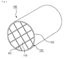
- Fig. 1 is a perspective view that schematically shows one example of a honeycomb structured body of the present invention.
- Fig. 2(a) is a perspective view that schematically shows one example of a honeycomb fired body that constitutes the honeycomb structured body of the present invention, and
- Fig. 2(b) is an A-A line cross-sectional view of the honeycomb fired body shown in Fig. 2(a) .
- a honeycomb structured body 100 shown in Fig. 1 has a structure in which a plurality of porous silicon carbide honeycomb fired bodies 110 having a shape shown in Figs. 2(a) and 2(b) are combined with one another with an adhesive layer 101 interposed therebetween to form a ceramic block 103, with a peripheral sealing material layer 102 formed on the periphery 121 of the ceramic block 103.
- the honeycomb fired body 110 shown in Figs. 2 (a) and 2 (b) has a structure in which a large number of cells 111 are longitudinally placed (the direction a in Fig. 2 (a) ) in parallel with one another with a cell wall 113 therebetween, and either one end of each of the cells 111 is sealed with a plug 112. Therefore, exhaust gases G having flowed into one of the cells 111 with an opening end on one end face surely passes through the cell wall 113 that separates the cells 111, and flows out from another cell 111 with an opening end on the other end face. Therefore, the cell wall 113 functions as a filter for capturing PM and the like.
- the adhesive layer 101 and the peripheral sealing material layer 102 are formed by using the sealing material for a honeycomb structured body of the present embodiment.
- the following description will discuss an embodiment of a method for manufacturing the honeycomb structured body of the present invention in which the honeycomb structured body is manufactured by using the sealing material for a honeycomb structured body of the present embodiment.
- a combining process for forming an adhesive layer between a plurality of honeycomb fired bodies and bonding the plurality of honeycomb fired bodies to one another with the adhesive layer interposed therebetween and a peripheral sealing material layer forming process for forming a peripheral sealing material layer on a peripheral face of a ceramic block will be described, and then all the processes for manufacturing a honeycomb structured body will be described.
- the method for forming the adhesive layer between the honeycomb fired bodies in the combining process is not particularly limited. As one example thereof, the following description will discuss a method in which the gap between the honeycomb fired bodies is filled with the adhesive including the sealing material for a honeycomb structured body of the present embodiment and the adhesive is dried and solidified to form an adhesive layer.
- Fig. 3 is a cross-sectional view that schematically shows a cross-section obtained by cutting one example of a parallel-arranged body of honeycomb fired bodies in a direction perpendicular to the longitudinal direction thereof.
- a plurality of honeycomb fired bodies 110 are placed in parallel with one another in columns and rows, with a spacer 410 interposed therebetween.
- the spacer is designed to have the same thickness as the thickness of the adhesive layer to be formed between the honeycomb fired bodies. Therefore, a gap 420 corresponding to the thickness of the spacer is formed between the honeycomb fired bodies.
- 16 pieces of honeycomb fired bodies are placed in parallel with one another in four columns and four rows to form a parallel-arranged body 180 of honeycomb fired bodies.
- FIG. 4 is a cross-sectional view that schematically shows a cross-section obtained by cutting one example of a filling apparatus and a parallel-arranged body of honeycomb fired bodies placed in an inner space, in a direction parallel to the longitudinal direction of the parallel-arranged body.
- a filling apparatus 500 is provided with a tubiform 501 and a paste supply device 503.
- the tubiform 501 is provided with an inner space 502 which is allowed to accommodate a parallel-arranged body 180 of honeycomb fired bodies.
- the paste supply device 503 is provided with a paste chamber 520 for housing a paste-form adhesive 10 including the sealing material for a honeycomb structured body of the present embodiment and an extruding mechanism 525 for extruding the adhesive 10 out of the paste chamber.
- a paste chamber 520 for housing a paste-form adhesive 10 including the sealing material for a honeycomb structured body of the present embodiment and an extruding mechanism 525 for extruding the adhesive 10 out of the paste chamber.
- the laminated body of the honeycomb fired bodies is heated by using a drying apparatus or the like to dry and solidify the adhesive, and an adhesive layer is subsequently formed so that the honeycomb fired bodies are bonded to one another.
- a rectangular pillar-shaped ceramic block comprising 16 pieces of honeycomb fired bodies can be manufactured.
- a periphery cutting process is carried out to form the ceramic block into a round pillar-shape by cutting the side faces of the ceramic block using a diamond cutter or the like.
- the method for forming a peripheral sealing material layer on the peripheral face of the ceramic block is not particularly limited, and example thereof include a method in which the sealing material for a honeycomb structured body of the present embodiment is applied to the peripheral face of a ceramic block by using a squeegee to form a peripheral sealing material paste layer, and the sealing material for a honeycomb structured body is dried and solidified.
- honeycomb structured body silicon carbide powders having different average particle diameters, an organic binder, a plasticizer in liquid form, a lubricant and water are mixed to prepare a wet mixture for manufacturing a molded body.
- this wet mixture is loaded into an extrusion molding machine.
- the wet mixture is extrusion-molded into a honeycomb molded body having a predetermined shape.
- the honeycomb molded body is cut into a predetermined length, and dried by using a drying apparatus, such as a microwave drying apparatus, a hot-air drying apparatus, a dielectric drying apparatus, a reduced-pressure drying apparatus, a vacuum drying apparatus and a freeze drying apparatus, and a sealing process is carried out by filling predetermined cells with a plug material paste to be a plug for sealing the cells.
- a drying apparatus such as a microwave drying apparatus, a hot-air drying apparatus, a dielectric drying apparatus, a reduced-pressure drying apparatus, a vacuum drying apparatus and a freeze drying apparatus
- a degreasing process is carried out to remove the organic components in the honeycomb molded body by heating the honeycomb molded body in a degreasing furnace. Then, a firing process is carried out to manufacture a honeycomb fired body. Through the above-mentioned processes, the honeycomb fired body is manufactured.
- conditions conventionally used upon manufacturing a honeycomb fired body are applicable for carrying out the cutting, drying, sealing, degreasing and firing processes.
- the combining process, the periphery cutting process and the peripheral sealing material layer forming process are carried out by using the honeycomb fired bodies thus manufactured to manufacture a honeycomb structured body.
- the sealing material for a honeycomb structured body is 4 or more, the inorganic particles are not allowed to aggregate after preparation of the paste. Moreover, since the pH of the sealing material for a honeycomb structured body is 6 or less, the sealing material is not allowed to gelate even after preparation of the paste. For this reason, it is possible to prevent a deterioration in the flowability of the paste and an increase in the viscosity thereof, even a long time after preparation of the paste. Therefore, even a long time after preparation of the paste, the sealing material for a honeycomb structured body is allowed to maintain superior coating properties to the ceramic block and the like.
- the average particle diameter of the oxide sol in the sealing material for a honeycomb structured body is 5 to 30 nm.
- the oxide sol having an average diameter of 5 to 30 nm is easily prepared or easily available.
- the sealing material for a honeycomb structured body is prepared by mixing an acidic solution with an alkaline mixture, the pH of the sealing material can be easily controlled in a range of 4 to 6 without using an alkaline solution. Furthermore, use of a lactic acid solution as the acidic solution enhances the safety upon carrying out the processes for preparing the sealing material for a honeycomb structured body.
- the gap between the honeycomb fired bodies is filled with the sealing material for a honeycomb structured body of the present embodiment. Since the sealing material for a honeycomb structured body in the present embodiment shows no decrease in the flowability and no increase in the viscosity of the paste even a long time after preparation of the paste, it is possible to easily fill with the sealing material for a honeycomb structured body as an adhesive.
- the sealing material for a honeycomb structured body of the present embodiment is applied to the peripheral face of the ceramic block. Since the sealing material for a honeycomb structured body in the present embodiment shows no decrease in the flowability and no increase in the viscosity of the paste even a long time after preparation of the paste, it is possible to improve the workability upon forming the peripheral sealing material paste layer on the peripheral face of the ceramic block in the peripheral sealing material layer forming process.
- a sealing material for a honeycomb structured body was prepared by using an oxide sol having an average particle diameter of 5 to 40 nm and either one of inorganic fibers A and B having a composition shown in Table 1.
- both of the inorganic fibers A and B were biosoluble fibers, and the inorganic fibers A mainly contain CaO as the alkaline earth metal compound, and the inorganic fibers B mainly contain MgO as the alkaline earth metal compound.
- An amount of 43.9 parts by weight of the inorganic fibers A as the inorganic fibers, 36.8 parts by weight of SiC powders as the inorganic particles and 0.5 parts by weight of carboxymethylcellulose (CMC) as an organic binder were mixed to prepare a mixture, and 20.4 parts by weight of an alkaline oxide sol having an average particle diameter of 12 ⁇ m and 15.7 parts by weight of water were further added to the mixture to prepare an alkaline mixture.
- the pH of this alkaline mixture was 8.5.
- a lactic acid aqueous solution pH 2.0 was added as an acidic solution to adjust the pH of the mixture to 5.0, and the mixture was further mixed and kneaded to prepare a sealing material for a honeycomb structured body.
- Sealing materials for a honeycomb structured bodies were prepared by following the same procedure as in Example 1 except that the amount of the lactic acid aqueous solution was changed or the kind and the amount of the acidic solution were changed to adjust the pH of the respective sealing materials for a honeycomb structured bodies as shown in Table 2.
- a sealing material for a honeycomb structured body was prepared by following the same procedure as in Example 1 except that the lactic acid aqueous solution was not added.
- Table 2 collectively shows the average particle diameter of the oxide sol, the kinds of the inorganic fibers and the acidic solution and the like.
- Sealing materials for a honeycomb structured body were prepared by following the same procedure as in Example 1 except that the average particle diameters of the oxide sols contained in the respective sealing materials for a honeycomb structured body were 5 ⁇ m, 23 ⁇ m, 30 ⁇ m and 40 ⁇ m as shown in Table 3.
- Table 3 collectively shows the kinds of the oxide sol, the inorganic fibers and the acidic solution used in Examples 4 to 6 and Reference Example 1, and the like.
- Sealing materials for a honeycomb structured body were prepared by following the same procedure as in Example 1 except that the kind of the inorganic fibers was changed in Example 7, and the kinds of the acidic solutions were changed in Examples 8 and 9.
- Table 4 collectively shows the kinds of the oxide sol, the inorganic fibers and the acidic solution used in Examples 7 to 9, and the like.
- honeycomb fired bodies were manufactured. First, manufacturing of the honeycomb fired bodies will be described, and then the respective evaluation methods will be described.
- the raw honeycomb molded body was dried by using a microwave drying apparatus to obtain a dried honeycomb molded body. Then, using a paste having the same composition as that of the raw molded body, predetermined cells were filled, and the dried honeycomb molded body thus filled was again dried by using a drying apparatus.
- honeycomb fired body comprising a silicon carbide sintered body, with a porosity of 45%, an average pore diameter of 15 ⁇ m, a size of 34.3 mm ⁇ 34.3 mm ⁇ 150 mm, the number of cells (cell density) of 300 pcs/inch 2 and a thickness of the cell wall of 0.25 mm (10 mil), was manufactured.
- the flowability was measured on the respective sealing materials for a honeycomb structured body prepared in Examples, Comparative Examples and Reference Example by using a flowability measuring apparatus, immediately after preparation, one day, two days and three days after preparation, respectively.
- Fig. 5(a) is a side view that schematically shows the flowability measuring method
- Fig. 5(b) is a perspective view that schematically shows injection of the sealing material.
- the flowability measuring device 700 used for measuring the flowability shown in Fig. 5 (a) , is provided with a syringe 710 having a cylinder 711 for housing a liquid-form substance whose flowability is to be measured and a piston 712 for extruding the liquid-form substance, and a load cell 720 for moving the piston 712 and measuring a load applied to the piston 712.
- a predetermined amount of a sealing material 10 for a honeycomb structured body was loaded into the cylinder 711 of the syringe 710, and as shown in Fig. 5(b) , the tip of the syringe 710 is set to have contact with the opening of the cell 111 of a honeycomb fired body 110.
- a honeycomb fired body that had been cut into a predetermined length was used as the honeycomb fired body.
- the load cell 720 was moved 10 mm at a velocity of 10 mm/sec so that the sealing material 10 for a honeycomb structured body was extruded from the tip of the syringe 710, and injected into the cell 111.
- loads (N) applied to the piston upon injecting the sealing material for a honeycomb structured body were measured, and the largest value of the loads was defined as a value for flowability. That is, a sealing material for a honeycomb structured body having a higher value of the flowability flow tends to have difficulties to flow, and have poor flowability.
- Tables 2 to 4 show the flowability measured one day after preparation of the sealing materials for a honeycomb structured body.
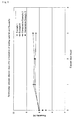
- Fig. 6 is a graph that shows the relationship between elapsed days after preparation and the flowability, with respect to the sealing materials for a honeycomb structured body of Examples 1 and 5, Comparative Examples 2 and 3.
- the sealing materials for a honeycomb fired body of Examples 1 and 5 there was hardly any change in the flowability even three days after preparation.
- the sealing materials for a honeycomb fired body of Comparative Examples 2 and 3 the values of flowability became higher (higher loads were required to allow the sealing materials for a honeycomb structured body to flow) and gelation developed together with the lapse of time.
- the sealing materials were no longer extruded from the syringe one day after preparation, thereby making it possible to measure the flowability.
- the viscosity was measured on the respective sealing materials for a honeycomb structured body prepared in Examples, Comparative Examples and Reference Example by using a B-type viscometer at a rotational speed of 10 rpm, immediately after preparation, one day, two days and three days after preparation, respectively.
- Tables 2 to 4 show the viscosity measured one day after preparation of the sealing materials for a honeycomb structured body.
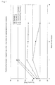
- Fig. 7 shows the relationship between elapsed days after preparation and the viscosity, with respect to the sealing materials for a honeycomb structured body of Examples 1 and 5, Comparative Examples 2 and 3.
- the sealing materials for a honeycomb fired body of Examples 1 and 5 there was hardly any change in the viscosity even three days after preparation.
- the sealing materials for a honeycomb fired body of Comparative Examples 2 and 3 the viscosity became higher and gelation developed together with the lapse of time. It was impossible to measure the viscosity two days after preparation of the sealing materials.
- honeycomb fired bodies 16 pieces of honeycomb fired bodies were arranged in four columns and four rows with a spacer interposed therebetween to form a parallel-arranged body of honeycomb fired bodies.
- the parallel-arranged body was placed in a filling device, and each of the sealing materials for a honeycomb structured body prepared in Examples, Comparative Examples and Reference Example was loaded into a paste chamber of the filling device. Then, a force of 800 gf (7. 85 N) was applied to the sealing material for a honeycomb structured body by using an extrusion mechanism to fill the gap between the honeycomb fired bodies with the sealing material for a honeycomb structured body.
- each sample (laminated body of honeycomb fired bodies) with the gap between honeycomb fired bodies desirably filled with the sealing material for a honeycomb structured body was heated at 120°C in a drying apparatus to form an adhesive layer by solidifying the sealing material for a honeycomb structured body so that a ceramic block was manufactured.
- the side faces of the ceramic block were cut into a cylindrical shape by using a diamond cutter, and each of the sealing materials for a honeycomb structured body prepared in respective Examples and Reference Examples was applied to the peripheral face of the cut ceramic block by using a squeegee to form a peripheral sealing material paste layer.
- the sealing material for a honeycomb structured body was solidified by heating at 120°C in a drying apparatus to form a peripheral sealing material layer, and thus a honeycomb structured body was manufactured.
- a sample (69 mm in width ⁇ 34.3 mm in depth ⁇ 25 mm in height) is cut out from the manufactured honeycomb structured body to have an adhesive layer (thickness: 1mm) vertically positioned in the middle portion thereof and two honeycomb fired bodies (size: 34.3 mm ⁇ 34.3 mm ⁇ 25 mm) positioned on the opposite sides of the adhesive layer.
- the three-point bending test was carried out in accordance with JIS R 1601 on each sample thus manufactured to measure an adhesive strength (load) between the honeycomb fired bodies.
- a loaded point was set to be on a part of the adhesive layer, and then the three-point bending test was carried out by using an Instron tensile meter to measure a load (N) at the time of breakage.
- Fig. 8 shows the relationship between the average particle diameter of the oxide sol and the adhesive strength between the honeycomb fired bodies.
- the results of the measurement of the adhesive strength show that the sealing materials for a honeycomb structured body containing the oxide sol with an average particle diameter of 30 nm or less have an adhesive strength of as high as 200 N or more. In contrast, the sealing materials for a honeycomb fired bodies containing the oxide sol with an average particle diameter exceeding 30 nm have a slightly low adhesive strength of 60 N.
- the adhesive strength between the ceramic block and the peripheral sealing material layer was evaluated.
- an apparatus for evaluating the adhesive strength an apparatus including: a 2L (litter) common-rail-type diesel engine; an exhaust-gas pipe connected to the honeycomb filter, which allows exhaust gases from the engine to pass through; and a honeycomb filter having a metal casing in which each honeycomb structured body was housed, was used.
- the engine was driven at the number of revolutions of 2000 min -1 and a torque of 47 Nm so that exhaust gases from the engine were allowed to pass through each of the honeycomb structured bodies, and 10 minutes of regenerating treatment of the honeycomb structured bodies by using a post-injection system was conducted for every driving operation corresponding to a travel distance of 500 km. This was defined as one cycle. After repeating this cycle 200 times, the state of the peeling of the peripheral sealing material layer from the peripheral face of the ceramic block was visually observed. In Tables 2 to 4, "good” indicated that no peeling was observed between the peripheral sealing material layer and the peripheral face of the ceramic block, and "bad” indicated that peeling was observed.
- the results show that the sealing material for a honeycomb structured body containing the oxide sol with an average particle diameter of 30 nm or less had no peeling between the peripheral sealing material layer and the peripheral face of the ceramic block.
- the sealing materials for a honeycomb structured body containing the oxide sol with an average particle diameter exceeding 30 nm had peeling between the peripheral sealing material layer and the peripheral face of the ceramic block.
- a sealing material for a honeycomb structured body was prepared by using an alkaline silica sol having an average particle diameter of 5 to 40 nm and a pH of 10.0 as the oxide sol, and the composition of the alkaline silica sol was 30.6% by weight of SiO 2 , 0.23% by weight of Al 2 O 3 and 69.2% by weight of H 2 O. Then, the same tests as in respective Examples, Reference Example and Comparative Examples were carried out, and consequently, the same results as those of respective Examples, Reference Example and Comparative Examples were obtained.
- the respective evaluation results of properties, such as the flowability, viscosity and filling properties, measured on the sealing material for a honeycomb structured body manufactured in each of present Examples and Reference Example were similar to the evaluation results of the properties, such as the flowability, viscosity and filling properties, of conventionally-used sealing materials for a honeycomb structured body using non biosoluble fibers (for example, a sealing material for a honeycomb structured body containing non biosoluble silica-alumina fibers, silicon carbide, methylcellulose, silica sol and water).
- non biosoluble fibers for example, a sealing material for a honeycomb structured body containing non biosoluble silica-alumina fibers, silicon carbide, methylcellulose, silica sol and water.
- the composition of the sealing material for a honeycomb structured body and the structure of the honeycomb structured body are the same as in the first embodiment, a different method for forming an adhesive layer is used in the method for manufacturing a honeycomb structured body.
- Fig. 9 is an explanatory view that schematically shows a method for applying an adhesive to side faces of a honeycomb fired body.
- a honeycomb fired body 110 was placed to be inclined on a base 400 having an upper portion with a V-shaped cut surface which allows lamination of the honeycomb fired bodies 110 being inclined.
- a paste-form adhesive including the sealing material for a honeycomb structured body is applied with an even thickness to two side faces 110a and 110b facing upward.
- another honeycomb fired body 110 was repeatedly laminated on the adhesive 10.
- a laminated body of honeycomb fired bodies in which the adhesive is applied to the side faces of each honeycomb fired bodies is manufactured.
- the laminated body of the honeycomb fired bodies is heated by using a drying apparatus or the like, and the adhesive is subsequently dried and solidified to form an adhesive layer between the honeycomb fired bodies.
- the present embodiment makes it possible to produce the following effect.
- honeycomb fired bodies having a different shape from that of the first embodiment are used and different methods for forming an adhesive layer and a peripheral sealing material layer from those of the first embodiment are used in the method for manufacturing a honeycomb structured body.
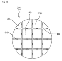
- Fig. 10 is a cross-sectional view that schematically shows a cross-section of another example of a parallel-arranged body of honeycomb fired bodies, obtained by cutting in a direction perpendicular to the longitudinal direction thereof.
- three kinds of honeycomb fired bodies 120, 130 and 140 each having a different shape in the cross-section perpendicular to the longitudinal direction thereof are manufactured.
- the cross-section of each honeycomb fired body 120 has a shape surrounded by two straight lines and one curve
- the cross-section of each honeycomb fired body 130 has a shape surrounded by three straight lines and one curve
- the cross-section of each honeycomb fired body 140 has a shape surrounded by four straight lines.
- These honeycomb fired bodies having mutually different cross-sectional shapes can be manufactured by altering the shape of a die to be used for extrusion-molding.
- honeycomb fired bodies 120, 130 and 140 are placed in parallel with one another in columns and rows, with a spacer 410 interposed therebetween to form a parallel-arranged body 280 of honeycomb fired bodies having a virtually round shape in its cross-section perpendicular to the longitudinal direction.
- a gap 420 having a thickness of the spacer is formed between the respective honeycomb fired bodies.
- the parallel-arranged body of honeycomb fired bodies is placed in a filling device having a cylindrical tubiform, and a gap formed between the honeycomb fired bodies and a gap formed between the honeycomb fired bodies and the tubiform were filled with a sealing material for a honeycomb structured body.
- Fig. 11 is a cross-sectional view that schematically shows a cross-section obtained by cutting another example of a filling apparatus and a parallel-arranged body of honeycomb fired bodies placed in an inner space, in a direction parallel to the longitudinal direction of the parallel-arranged body of the honeycomb fired bodies.
- Fig. 11 shows the cross-section taken to include the honeycomb fired body 130 and the honeycomb fired body 140.
- a filling device 600 used in the present embodiment is provided with a cylindrical tubiform 601 and a paste supply device 603.
- the tubiform 601 has a slightly larger inner diameter than the diameter of the parallel-arranged body 280 of honeycomb fired bodies to be placed therein. Therefore, when the parallel-arranged body 280 of honeycomb fired bodies is placed in the inner space 602 of the tubiform 601, a gap 430 is formed between the tubiform 601 and the parallel-arranged body 280 of honeycomb structured bodies.
- the paste supply device 603 and the extrusion mechanism 625 are designed to be virtually the same as the paste supply device 503 and the extrusion mechanism 525 shown in Fig. 4 , and configured so that the gap 420 between the honeycomb fired bodies and the gap 430 between the tubiform 601 and the parallel-arranged body 280 of the honeycomb fired bodies are simultaneously filled with the sealing material 10 for a honeycomb structured body housed in the paste chamber 620.
- the gap between the honeycomb fired bodies and the gap between the parallel-arranged body of honeycomb fired bodies and the tubiform are filled with the sealing material for a honeycomb structured body.
- the sealing material for a honeycomb structured body is dried and solidified so that the adhesive layer between the honeycomb fired bodies, and thus the peripheral sealing material layer are simultaneously formed.
- the present embodiment makes it possible to produce the following effect.
- the composition of the sealing material for a honeycomb structured body is the same as that of the first embodiment, the shape of the honeycomb structured body and the method for manufacturing a honeycomb structured body are different from those of the first embodiment.
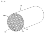
- FIG. 12 is a perspective view that schematically shows another example of the honeycomb structured body of the present invention.
- a honeycomb structured body 150 shown in Fig. 12 comprises a ceramic block 155 including a single piece of a pillar-shaped honeycomb fired body in which a large number of cells 151 are longitudinally placed in parallel with one another with a cell wall 152 therebetween, and a peripheral sealing material layer 154 is formed on the periphery of the ceramic block 155.
- honeycomb fired bodies are manufactured by following the same procedure as in the first embodiment, except that a honeycomb molded body having a virtually cylindrical shape is formed by altering the shape of a die used for extrusion-molding. This honeycomb fired body is allowed to form a ceramic block without the combining process. Thereafter, a peripheral sealing material layer forming process in which a peripheral sealing material layer is formed on the peripheral face of the ceramic block by using the sealing material for a honeycomb structured body of the first embodiment is carried out.
- the same method as that of the first embodiment in which the sealing material for a honeycomb structured body is applied to the peripheral face of the ceramic block by using a squeegee may be used, or the same method as that of the third embodiment in which the gap formed between the peripheral face of the ceramic block and the tubiform is filled with the sealing material for a honeycomb structured body by using a filling apparatus, may be used.
- the present embodiment also makes it possible to produce the following effect.
- the sealing material for a honeycomb structured body used to form the adhesive layer and the sealing material used to form the peripheral sealing material layer may include the same materials or different materials.
- an adhesive paste that has been conventionally used for manufacturing a honeycomb structured body may be used.
- the shape of the honeycomb fired bodies is preferably designed to easily combine the honeycomb fired bodies with one another when forming a honeycomb structured body.
- a square, rectangular, hexagonal, sector shape or the like may be used as its cross-sectional shape.
- the shape of the honeycomb structured body of the present invention is not particularly limited to a round pillar-shape, and may be a desired pillar shape such as a cylindroid shape and a polygonal pillar shape.
- the porosity of the honeycomb fired body is not particularly limited, and desirably 35 to 60%.
- the porosity of less than 35% may easily cause clogging in the honeycomb structured body.
- the porosity exceeding 60% may cause a reduction in the strength of the honeycomb fired body, resulting in easy breakage.
- the average pore diameter of the honeycomb fired body is desirably 5 to 30 ⁇ m.
- the average pore diameter of less than 5 ⁇ m may easily cause clogging due to particulates.
- the average pore diameter exceeding 30 ⁇ m may cause particulates to easily pass through the pores.
- the honeycomb fired body may fail to capture the particulates, resulting in a failure in functioning as a filter.
- the porosity and the average pore diameter can be measured through conventionally known methods such as a mercury porosimetry, Archimedes method, and a measuring method using a scanning electronic microscope (SEM).
- the cell density in the cross-section perpendicular to the longitudinal direction of the honeycomb fired body is not particularly limited.
- a desirable lower limit thereof is 31.0 pcs/cm 2 (200 pcs/inch 2 ) and a desirable upper limit is 93.0 pcs/cm 2 (600 pcs/inch 2 ).
- a more desirable lower limit is 38.8 pcs/cm 2 (250 pcs/inch 2 ) and a more desirable upper limit is 77.5 pcs/cm 2 (500 pcs/inch 2 ).
- the thickness of the cell walls of the honeycomb fired body is not particularly limited, and desirably 0.1 to 0.4 mm.
- the main component of constituent materials of the honeycomb fired body is not limited to silicon carbide.
- ceramic materials may comprise ceramic powders, for example, nitride ceramics such as aluminum nitride, silicon nitride, boron nitride and titanium nitride; carbide ceramics such as zirconium carbide, titanium carbide, tantalum carbide and tungsten carbide; oxide ceramics such as alumina, zirconia, cordierite, mullite, and aluminum titanate; and the like.
- non-oxide ceramics are preferable, and silicon carbide is more preferable because this is excellent in thermal resistance properties, mechanical strength, thermal conductivity and the like.
- examples of the constituent material of the honeycomb fired body also include silicon-containing ceramics, in which metallic silicon is blended with the above-described ceramics, as well as a ceramic material such as ceramic bound by silicon or silicate compounds. And among these, those ceramics (silicon-containing silicon carbide) in which metallic silicon is blended with silicon carbide are desirably used. Especially, a silicon-containing silicon carbide ceramic containing 60% by weight or more of silicon carbide is desirable.
- the particle diameter of the ceramic powder is not particularly limited, and the ceramic powder that tends not to cause the case where the size of the honeycomb fired body manufactured by the following firing treatment becomes smaller than that of the honeycomb molded body after degreased is preferable.
- the organic binder used when forming the wet mixture is not particularly limited, and examples thereof include methylcellulose, carboxymethylcellulose, hydroxyethylcellulose, polyethylene glycol, and the like. Methylcellulose is desirable among these.
- a blending amount of the organic binder is desirably 1 to 10 parts by weight with respect to 100 parts by weight of ceramic powder.
- the plasticizer used when forming the wet mixture is not particularly limited, and examples thereof include glycerin and the like.
- the lubricant is not particularly limited, and examples thereof include polyoxyalkylene-based compounds such as polyoxyethylene alkyl ether and polyoxypropylene alkyl ether, and the like. Specific examples of the lubricant include polyoxyethylene monobutyl ether, polyoxypropylene monobutyl ether, and the like.
- the plasticizer and the lubricant may not be contained in the wet mixture in some cases.
- a dispersant solution may be used upon preparing a wet mixture, and examples of the dispersant solution include water, an organic solvent such as benzene, alcohol such as methanol, and the like.
- a molding auxiliary may be added to the wet mixture.
- the molding auxiliary is not particularly limited, and examples thereof include ethylene glycol, dextrin, fatty acid, fatty acid soap, polyalcohol and the like.
- a pore-forming agent such as balloons that are fine hollow spheres including oxide-based ceramics, spherical acrylic particles, graphite and the like may be added to the wet mixture, if necessary.
- the balloon is not particularly limited, and examples thereof include alumina balloon, glass micro balloon, shirasu balloon, fly ash balloon (FA balloon), mullite balloon and the like. Alumina balloon is desirable among these.
- the plug material paste for sealing the cells is not particularly limited, a plug to be manufactured through the subsequent processes desirably has a porosity of 30 to 75%, and for example, it is possible to use a plug material paste having the same composition as that of the wet mixture of the raw material.
- the catalyst to convert and/or purify exhaust gases may be supported on the honeycomb structured body, and desirable examples of the catalyst to be supported include noble metals such as platinum, palladium and rhodium. Platinum is more desirable among these. Moreover, an alkali metal such as potassium and sodium, and an alkali earth metal such as barium may be used as other catalysts. These catalysts may be used alone, or two or more kinds of these may be used in combination.
- honeycomb structured body the honeycomb structured body (honeycomb filter) in which either one end portion of each of the cells is sealed is described.
- honeycomb structured body of the present invention need not have an end portion of each cell sealed.
- Such a honeycomb structured body may be desirably used as a catalyst supporting carrier.
Landscapes
- Chemical & Material Sciences (AREA)
- Engineering & Computer Science (AREA)
- Ceramic Engineering (AREA)
- Materials Engineering (AREA)
- Organic Chemistry (AREA)
- Structural Engineering (AREA)
- Manufacturing & Machinery (AREA)
- Inorganic Chemistry (AREA)
- Chemical Kinetics & Catalysis (AREA)
- Nanotechnology (AREA)
- Physics & Mathematics (AREA)
- Composite Materials (AREA)
- Condensed Matter Physics & Semiconductors (AREA)
- General Physics & Mathematics (AREA)
- Crystallography & Structural Chemistry (AREA)
- Filtering Materials (AREA)
- Chemical Or Physical Treatment Of Fibers (AREA)
- Ceramic Products (AREA)
- Catalysts (AREA)
Abstract
Description
- The present invention relates to a sealing material for a honeycomb structured body, a honeycomb structured body and a method for manufacturing a honeycomb structured body.
- In a honeycomb structured body used as a filter for removing particulates and the like from exhaust gases discharged from an internal combustion engine such as a diesel engine, or as a catalyst supporting carrier for removing toxic components such as HC and CO from the exhaust gases, inorganic fibers have been used as materials for various constituent members.
Specific examples thereof includes a sealing material containing inorganic fibers such as a sealing material (adhesive) for combining a plurality of honeycomb fired bodies to form a ceramic block and a sealing material (peripheral sealing material) to be formed on the periphery of a ceramic block. - In the case when such inorganic fibers remain in the human body, in particular, in lungs or the like, they might be harmful to the human body. Therefore, the inorganic fibers used in the sealing material are desirably highly safe to the human body.
-
Patent Document 1 has described a sealing material containing, as inorganic fibers, at least one kind selected from the group consisting of an alkali metal compound, an alkaline earth metal compound and a boron compound. - The compound included in the inorganic fibers, described in
Patent Document 1, are so-called biosoluble fibers. The biosoluble fibers are soluble in physiological saline solution. Therefore, even when taken into the human body, the biosoluble fibers are dissolved and discharged out of the body, and are subsequently considered to be highly safe to the human body.
Patent Document 1:WO05/110578 Al - The above-mentioned sealing material is prepared in the form of a paste by mixing an inorganic binder, an organic binder, inorganic particles, water and the like with the inorganic fibers, because the sealing material is applied to a ceramic block or a honeycomb fired body when used.
- However, when the sealing material is prepared by using the biosoluble fibers as the inorganic fibers, and an oxide sol as the inorganic binder, aggregation or gelation tends to occur in the sealing material as the time elapses after preparation of the sealing material, leading to low flowability and a high viscosity of the paste.
When a phenomenon such as aggregation or gelation occurs in the sealing material, a problem arises in which applying of the sealing material to the ceramic block or the like becomes difficult. - The present invention has been devised to solve these problems, and its object is to provide a sealing material for a honeycomb structured body containing well biosoluble inorganic fibers and having superior coating properties to a ceramic block or the like even a long time after preparation of the paste.
Moreover, another object is to provide a honeycomb structured body manufactured by using the above-mentioned sealing material for a honeycomb structured body and also to provide a method for manufacturing such the above-mentioned honeycomb structured body. - The inventors of the present invention have intensively examined causes for aggregation or gelation in the sealing material. As a result, the inventors have found that, when the paste is alkaline, in particular, has a pH exceeding 6, gelation in the sealing material tends to occur due to gelation of the oxide sol.
- Here, in the present description, the term "gelation" refers to a phenomenon of aggregation of solid components dispersed in a sol, which is caused by a change in the pH or the like and causes an increase in the viscosity.
- Normally, electrical double layers are formed on the surfaces of the inorganic particles and the oxide sol contained in the sealing material. The electrical double layers are considered to allow the inorganic particles and the oxide sol to stably exist dispersed.
However, when the pH exceeds 6, polyvalent metal ions (Ca2+, Mg2+) contained in the biosoluble fibers elute and interfere with the surface charge of the oxide sol. Therefore, the charge balance on the surface of the oxide sol is disturbed, leading to aggregation of the oxide sol. This is presumably the reason why gelation occurs in the sealing material.
The pH of the paste is considered to give influences to the reaction rate between the polyvalent metal ions and the oxide sol. Under high pH conditions, the reaction rate is faster so that gelation of the sealing material easily progresses. - Moreover, the inventors of the present invention have also found that, when the paste is acidic, in particular, has a pH of less than 4, the inorganic particles in the paste tend to aggregate.
- Based upon the examination results, the inventors of the present invention have found that it is possible to provide a sealing material for a honeycomb structured body having coating properties to the ceramic block or the like even a long time after preparation of the paste by controlling the pH of the sealing material for a honeycomb structured body in a suitable range, and consequently have completed the present invention.
- Namely, the sealing material for a honeycomb structured body according to
claim 1 comprises inorganic fibers, oxide sol and inorganic particles, wherein the inorganic fibers include at least one kind selected from the group consisting of an alkali metal compound, an alkaline earth metal compound and a boron compound, and a pH of the sealing material for a honeycomb structured body is 4 to 6. - The inorganic fibers contained in the sealing material for a honeycomb structured body according to
claim 1 includes at least one kind selected from the group consisting of an alkali metal compound, an alkaline earth metal compound and a boron compound. Since these compounds are so-called biosoluble fibers, it is possible to provide a sealing material for a honeycomb structured body that is highly safe to the human body. - Moreover, since the pH of the sealing material for a honeycomb structured body is 4 or more, inorganic particles are not allowed to aggregate after preparation of the paste. Moreover, since the pH of the sealing material for a honeycomb structured body is 6 or less, the sealing material is not allowed to gelate after preparation of the paste.
For these reasons, it is possible to prevent a deterioration in the flowability of the paste and an increase in the viscosity thereof even a long time after preparation of the paste.
Therefore, it is possible to provide a sealing material for a honeycomb structured body that is has superior coating properties to the ceramic block or the like even a long time after preparation of the paste. - In the sealing material for a honeycomb structured body according to
claim 2, an acidic solution is mixed with an alkaline mixture containing an alkaline oxide sol as the oxide sol, the inorganic fibers and the inorganic particles.
In the sealing material for a honeycomb structured body according toclaim 3, a pH of the acidic solution is 1 to 3.
In the sealing material for a honeycomb structured body according toclaim 4, the acidic solution is a lactic acid aqueous solution. - In the sealing material for a honeycomb structured body according to
claim 5, an average particle diameter of the oxide sol is 5 to 30 nm.
By using the oxide sol having an average particle diameter of 5 to 30 nm, when a peripheral sealing material layer is formed on the peripheral face of the ceramic block by using the sealing material for a honeycomb fired body, it is possible to increase the adhesive strength between the ceramic block and the peripheral sealing material layer. - Moreover, by using the oxide sol having an average particle diameter of 5 to 30 nm, when the sealing material for a honeycomb structured body is used as an adhesive for bonding honeycomb fired bodies to one another, it is possible to increase the adhesive strength between the honeycomb fired bodies.
- In the sealing material for a honeycomb structured body according to
claim 6, the oxide sol is silica sol. - Namely, the honeycomb structured body according to claim 7 comprises a ceramic block including one or a plurality of pillar-shaped honeycomb fired bodies each having a large number of cells longitudinally placed in parallel with one another with a cell wall interposed therebetween; and a peripheral sealing material layer formed on a peripheral face of the ceramic block, wherein the peripheral sealing material layer is formed by drying and solidifying a sealing material for a honeycomb structured body containing inorganic fibers, oxide sol and inorganic particles and having a pH of 4 to 6, the inorganic fibers selected from the group consisting of an alkali metal compound, an alkaline earth metal compound and a boron compound.
- The inorganic fibers contained in the sealing material for a honeycomb structured body according to claim 7 includes at least one kind selected from the group consisting of an alkali metal compound, an alkaline earth metal compound and a boron compound, and the inorganic fibers including the above-mentioned compound are also contained in the peripheral sealing material layer. Since these compounds are so-called biosoluble fibers, it is possible to manufacture a honeycomb structured body that is highly safe to the human body.
- In the honeycomb structured body according to
claim 8, the ceramic block comprises the plurality of the honeycomb fired bodies and an adhesive layer formed between side faces of the honeycomb fired bodies. - In the honeycomb structured body according to claim 9, the adhesive layer is formed by drying and solidifying the sealing material for a honeycomb structured body.
Since the inorganic fibers contained in the adhesive layer are biosoluble fibers, it is possible to provide a honeycomb structured body that is highly safe to the human body and includes the plurality of the honeycomb fired bodies combined with one another with the adhesive layer interposed therebetween. - In the honeycomb structured body according to
claim 10, the sealing material for a honeycomb structured body is formed by mixing an acidic solution with an alkaline mixture containing an alkaline oxide sol as the oxide sol, the inorganic fibers and the inorganic particles.
In the honeycomb structured body according to claim 11, a pH of the acidic solution is 1 to 3.
In the honeycomb structured body according to claim 12, the acidic solution is a lactic acid aqueous solution. - In the honeycomb structured body according to claim 13, an average particle diameter of the oxide sol is 5 to 30 nm.
When the average particle diameter of the oxide sol in the sealing material for a honeycomb structured body is 5 to 30 nm, it is possible to increase the adhesive strength between the ceramic block and the peripheral sealing material layer. - Moreover, when the ceramic block includes a plurality of the honeycomb fired bodies and the adhesive layer formed between the honeycomb fired bodies, and the adhesive layer is formed by drying and solidifying the sealing material for a honeycomb structured body, by using the oxide sol having an average particle diameter of 5 to 30 nm, it is possible to increase the adhesive strength between the honeycomb fired bodies.
- In the honeycomb structured body according to claim 14, the oxide sol is silica sol.
- The method for manufacturing a honeycomb structured body according to
claim 15 is a method for manufacturing a honeycomb structured body, the honeycomb structured body including: a ceramic block including one or a plurality of pillar-shaped honeycomb fired bodies each having a large number of cells longitudinally placed in parallel with one another with a cell wall interposed therebetween; and a peripheral sealing material layer formed on a peripheral face of the ceramic block, the method comprising: preparing a sealing material for a honeycomb structured body containing inorganic fibers, oxide sol and inorganic particles and having a pH of 4 to 6, the inorganic fibers selected from the group consisting of an alkali metal compound, an alkaline earth metal compound and a boron compound; and forming a peripheral sealing material layer by forming a periphery sealing material paste layer including the sealing material for a honeycomb structured body on a peripheral face of the ceramic block and drying and solidifying the sealing material for a honeycomb structured body. - In the method for manufacturing a honeycomb structured body according to
claim 15, since the sealing material for a honeycomb structured body to be prepared in the preparing a sealing material for a honeycomb structured body has a pH of 4 or more, inorganic particles are not allowed to aggregate after preparation of the paste. Moreover, since the pH of the sealing material for a honeycomb structured body is 6 or less, the sealing material is not allowed to galete after preparation of the paste.
For these reasons, even a long time after preparation of the paste, it is possible to prevent a deterioration in the flowability of the paste and an increase in the viscosity thereof. Thus, the operability when forming a peripheral sealing material paste layer on the peripheral face of the ceramic block in the forming a peripheral sealing material layer can be improved. - Moreover, it is possible to form a peripheral sealing material layer containing inorganic fibers including at least one kind selected from the group consisting of an alkali metal compound, an alkaline earth metal compound and a boron compound. Since these compounds are so-called biosoluble fibers, it is possible to manufacture a honeycomb structured body that is highly safe to the human body.
- In the method for manufacturing a honeycomb structured body according to claim 16, the forming a peripheral sealing material layer includes forming the peripheral sealing material paste layer by applying the sealing material for a honeycomb structured body to the peripheral face of the ceramic block.
- The method for manufacturing a honeycomb structured body according to claim 17 further comprises: combining the plurality of the honeycomb fired bodies by applying an adhesive to side faces of the plurality of the honeycomb fired bodies, laminating the plurality of the honeycomb fired bodies, and then bonding the plurality of the honeycomb fired bodies by interposing an adhesive layer formed by drying and solidifying the adhesive; or combining the plurality of the honeycomb fired bodies by arranging the plurality of the honeycomb fired bodies with a predetermined sized gap maintained therebetween, filling the gap with an adhesive, and then bonding the plurality of the honeycomb fired bodies by interposing an adhesive layer formed by drying and solidifying the adhesive.
- In the method for manufacturing a honeycomb structured body according to claim 18, the sealing material for a honeycomb structured body is used as the adhesive.
By using the sealing material for a honeycomb structured body as an adhesive, it is possible to prevent a deterioration in the flowability of the sealing material for a honeycomb structured body and an increase in the viscosity thereof.
For this reason, the operability when applying the adhesive to side faces of each honeycomb fired body and the operability when filling with the adhesive a gap formed between the honeycomb fired bodies can be improved. - Moreover, it is possible to form an adhesive layer containing inorganic fibers including at least one kind of compound selected from the group consisting of an alkali metal compound, an alkaline earth metal compound and a boron compound. Since these compounds are so-called biosoluble fibers, it is possible to manufacture a honeycomb structured body that is highly safe to the human body.
- The method for manufacturing a honeycomb structured body according to claim 19 further comprises: placing the plurality of the honeycomb fired bodies in a tubiform with a predetermined sized gap being maintained between the honeycomb fired bodies and a predetermined sized gap being maintained between the honeycomb fired bodies and the tubiform; filling with the sealing material for a honeycomb structured body the gap formed between the honeycomb fired bodies and the gap formed between the honeycomb fired bodies and the tubiform; and forming an adhesive layer between the honeycomb fired bodies and the peripheral sealing material layer by drying and solidifying the sealing material for a honeycomb structured body.
By using this method, it is possible to simultaneously and easily form the adhesive layer between the honeycomb fired bodies and the peripheral sealing material layer. - In the method for manufacturing a honeycomb structured body according to
claim 20, the preparing a sealing material for a honeycomb structured body includes mixing an acidic solution with an alkaline mixture containing an alkaline oxide sol as the oxide sol, the inorganic fibers and the inorganic particles.
In the method for manufacturing a honeycomb structured body according to claim 21, a pH of the acidic solution is 1 to 3. In the method for manufacturing a honeycomb structured body according to claim 22, the acidic solution is a lactic acid aqueous solution. - In order to adjust the pH of the sealing material for a honeycomb structured body in a range of 4 to 6, when a solution prior to adjusting the pH has a low pH, in particular, a pH of less than 4, the pH of the sealing material needs to be adjusted by using an alkaline solution. However, from the viewpoint of safety during the operation, it is preferable to avoid the use of the alkaline solution.
When an acidic solution is mixed with the alkaline mixture to prepare the sealing material for a honeycomb structured body as described in the method for manufacturing a honeycomb structured body according toclaim 20, it is possible to easily control the pH of the sealing material in a range of 4 to 6 without using an alkaline solution.
Moreover, when a lactic acid solution is used as the acidic solution, it is possible to further enhance the safety during the operation in the preparing a sealing material for a honeycomb structured body. - In the method for manufacturing a honeycomb structured body according to claim 23, an average particle size of said oxide sol is 5 to 30 nm.
When the average particle diameter of the oxide sol in the sealing material for a honeycomb structured body is 5 to 30 nm, it is possible to form a sealing material layer having a high adhesive strength between the ceramic block and the peripheral sealing material layer. - Moreover, when forming an adhesive layer between the honeycomb fired bodies, by using the oxide sol having an average particle diameter of 5 to 30 nm in the sealing material for a honeycomb structured body, it is possible to form an adhesive layer having a high adhesive strength between the honeycomb fired bodies.
- In the method for manufacturing a honeycomb structured body according to claim 24, the oxide sol is silica sol.
- Hereinafter, the sealing material for a honeycomb structured body, the honeycomb structured body and the method for manufacturing a honeycomb structured body of the present invention will be described with reference to the figures.
- First, the sealing material for a honeycomb structured body will be described.
A sealing material for a honeycomb structured body of the present embodiment comprises inorganic fibers, oxide sol and inorganic particles.
The above-mentioned inorganic fibers include at least one kind selected from the group consisting of an alkali metal compound, an alkaline earth metal compound and a boron compound.
Examples of the above-mentioned alkali metal compound include sodium oxide, potassium oxide and the like. Examples of the above-mentioned alkaline earth metal compound include magnesium oxide, calcium oxide, barium oxide and the like. Examples of the above-mentioned boron compound include boron oxide and the like. - Moreover, the lower limit of the content of the inorganic fibers contained in the sealing material for a honeycomb structured body is desirably 10% by weight, more desirably 20% by weight as solids content. The upper limit thereof is desirably 70% by weight, more desirably 40% by weight, further more desirably 30% by weight as solids content. The content of the inorganic fibers of less than 10% by weight may cause a deterioration in the elasticity. On the contrary, the content of the inorganic fibers exceeding 70% by weight causes a decrease in the adhesive strength as well in the thermal conductivity.
- Moreover, the lower limit of the fiber length is desirably 0.1 µm and the upper limit thereof is desirably 1000 µm, more desirably 100 µm, further more desirably 50 µm.
The fiber length less than 0.1 µm causes difficulties in manufacturing a honeycomb structured body having sufficient elasticity. The fiber length exceeding 1000 µm tends to cause pills in the form of fibers, making it difficult to form a thin adhesive layer or a thin peripheral sealing material layer, and also causes poor dispersal of the inorganic particles. - Moreover, the lower limit of the content of the oxide sol contained in the sealing material for a honeycomb structured body is desirably 1% by weight, more desirably 5% by weight as solids content. The upper limit thereof is desirably 30% by weight, more desirably 15% by weight, further more desirably 9% by weight as solids content. The content of the oxide sol of less than 1% by weight may cause a decrease in the adhesive strength. On the contrary, the content of the oxide sol exceeding 30% by weight causes decreases in the thermal conductivity.
- The lower limit of the content of the inorganic particles is desirably 3% by weight, more desirably 10% by weight, further desirably 20% by weight as solids content. The upper limit of the content of the inorganic particles is desirably 80% by weight, more desirably 60% by weight, further more desirably 40% by weight as solids contents. The content of the inorganic particles of less than 3% by weight tends to cause a decrease in thermal conductivity. On the contrary, the content thereof exceeding 80% by weight tends to cause a decrease in the adhesive strength, when the adhesive layer or the peripheral sealing material layer is exposed to high temperatures.
- The lower limit of the particle diameters of the inorganic particles is desirably 0.01 µm, more desirably 0.1 µm, and the upper limit of the particle diameters of the inorganic particles is desirably 100 µm, more desirably 15 µm, further more desirably 10 µm. Use of the inorganic particles having particle diameter of less than 0.01 µm may lead to high costs, and the particle diameter exceeding 100 µm tends to cause a decrease in the adhesive strength as well as in the thermal conductivity.
- Moreover, the inorganic fibers preferably further contain 60 to 85% by weight of silica, more preferably, 70 to 80% by weight thereof. The above-mentioned silica indicates SiO or SiO2.
Furthermore, the inorganic fibers preferably have a solubility of 0.03% or more in a physiological saline solution at 37°C. - Examples of the oxide sol include silica sol, alumina sol, zirconia sol and the like. These may be used alone, or two or more kinds of these may be used in combination. Silica sol is preferably used among these.
- Moreover, the average particle diameter of the oxide sol is preferably 5 to 30 nm.
By using an oxide sol having a smaller average particle diameter, the adhesive strength to bond the honeycomb fired body tends to be improved. However, it is difficult to manufacture the oxide sol having an average particle diameter of less than 5 nm, and such an oxide sol is hardly available. Moreover, the oxide sol having an average particle diameter exceeding 30 nm tends to cause a decrease in the adhesive strength to bond the honeycomb fired body. - Here, the average particle diameter of the oxide sol can be measured, for example, by using the following method.
Specifically, when the oxide sol is silica sol, first, the silica sol is dried, and its BET specific surface area is measured.
Thereafter, supposing that silica particles in the silica sol are spherical particles of a solid material, the particle diameter is calculated from the following formula (1):
(in the formula, ρ is the true density of silica (2.2 g/cm3).)
The particle diameter determined by this method is defined as the average particle diameter of the silica sol.
Moreover, the average particle diameter of the oxide sol can be directly measured by using, for example, TEM (Transmission Electron Microscope) and the like. - Examples of the inorganic particles may include carbides, nitrides and the like, and specific examples thereof may include inorganic powder, whiskers and the like made of silicon carbide, silicon nitride, boron nitride and the like. Each of these may be used alone, or two or more kinds of these may be used in combination. Silicon carbide, which is superior in thermal conductivity, is more preferably used among the inorganic particles.
It should be noted that in the present description, the whisker is included in the inorganic particles. - The sealing material for a honeycomb structured body of the present embodiment preferably includes an organic binder. Examples of the organic binder include polyvinyl alcohol, methylcellulose, ethylcellulose, carboxymethylcellulose and the like. These may be used alone, or two or more kinds of these may be used in combination. Carboxymethylcellulose is preferably used among the organic binder.
- The sealing material for a honeycomb structured body of the present embodiment has a pH of 4 to 6.
Examples of the method for preparing a sealing material for a honeycomb structured body having a pH adjusted in a range of 4 to 6 include the following method.
First, inorganic fibers, inorganic particles and an organic binder are mixed to prepare a mixture, and an alkaline oxide sol and an appropriate amount of water are further added to the mixture to prepare an alkaline mixture.
Although not particularly limited, the pH of the alkaline oxide sol is preferably 8.5 to 10.5.
Here, an alkaline silica sol is preferably used as the alkaline oxide sol. - Moreover, an acidic solution is mixed with the alkaline mixture to adjust the pH of the obtained paste in a range of 4 to 6.
Although not particularly limited, the pH of the acidic solution is preferably 1 to 3.
By mixing the acidic solution having a pH of 1 to 3 with the alkaline mixture, the pH of the paste can be easily adjusted to about 4.
Here, although not particularly limited, examples of the acidic solution include hydrochloric acid, sulfuric acid, nitric acid, phosphoric acid, lactic acid, acetic acid, formic acid and the like. In particular, a lactic acid aqueous solution is preferably used among these. By using the lactic acid aqueous solution, it is possible to enhance the safety upon carrying out the mixing operation. - Moreover, by using the method for adjusting the pH of the paste in a range of 4 to 6 by adding an acidic solution to the alkaline mixture, it is possible to adjust the pH of the paste without using a strong alkaline solution.
For this reason, it is possible to carry out the mixing operation safely.
Lastly, the paste having an adjusted pH is further mixed and kneaded to prepare the sealing material for a honeycomb structured body. - The following description will discuss the honeycomb structured body.
The honeycomb structured body of the present embodiment is manufactured by using the above-mentioned sealing material for a honeycomb structured body of the present embodiment.
Fig. 1 is a perspective view that schematically shows one example of a honeycomb structured body of the present invention.
Fig. 2(a) is a perspective view that schematically shows one example of a honeycomb fired body that constitutes the honeycomb structured body of the present invention, andFig. 2(b) is an A-A line cross-sectional view of the honeycomb fired body shown inFig. 2(a) . - A honeycomb structured
body 100 shown inFig. 1 has a structure in which a plurality of porous silicon carbide honeycomb firedbodies 110 having a shape shown inFigs. 2(a) and 2(b) are combined with one another with anadhesive layer 101 interposed therebetween to form aceramic block 103, with a peripheralsealing material layer 102 formed on the periphery 121 of theceramic block 103. - The honeycomb fired
body 110 shown inFigs. 2 (a) and 2 (b) has a structure in which a large number ofcells 111 are longitudinally placed (the direction a inFig. 2 (a) ) in parallel with one another with acell wall 113 therebetween, and either one end of each of thecells 111 is sealed with aplug 112. Therefore, exhaust gases G having flowed into one of thecells 111 with an opening end on one end face surely passes through thecell wall 113 that separates thecells 111, and flows out from anothercell 111 with an opening end on the other end face.
Therefore, thecell wall 113 functions as a filter for capturing PM and the like. - In the honeycomb structured
body 100 of the present embodiment, theadhesive layer 101 and the peripheralsealing material layer 102 are formed by using the sealing material for a honeycomb structured body of the present embodiment.
The following description will discuss an embodiment of a method for manufacturing the honeycomb structured body of the present invention in which the honeycomb structured body is manufactured by using the sealing material for a honeycomb structured body of the present embodiment. - First, a combining process for forming an adhesive layer between a plurality of honeycomb fired bodies and bonding the plurality of honeycomb fired bodies to one another with the adhesive layer interposed therebetween and a peripheral sealing material layer forming process for forming a peripheral sealing material layer on a peripheral face of a ceramic block will be described, and then all the processes for manufacturing a honeycomb structured body will be described.
- First, the following description will discuss the combining process.
The method for forming the adhesive layer between the honeycomb fired bodies in the combining process is not particularly limited. As one example thereof, the following description will discuss a method in which the gap between the honeycomb fired bodies is filled with the adhesive including the sealing material for a honeycomb structured body of the present embodiment and the adhesive is dried and solidified to form an adhesive layer. -
Fig. 3 is a cross-sectional view that schematically shows a cross-section obtained by cutting one example of a parallel-arranged body of honeycomb fired bodies in a direction perpendicular to the longitudinal direction thereof.
First, as shown inFig. 3 , a plurality of honeycomb firedbodies 110 are placed in parallel with one another in columns and rows, with aspacer 410 interposed therebetween. The spacer is designed to have the same thickness as the thickness of the adhesive layer to be formed between the honeycomb fired bodies. Therefore, agap 420 corresponding to the thickness of the spacer is formed between the honeycomb fired bodies.
In the present embodiment, 16 pieces of honeycomb fired bodies are placed in parallel with one another in four columns and four rows to form a parallel-arrangedbody 180 of honeycomb fired bodies. - Successively, the gap formed between the honeycomb fired bodies placed in parallel with one another is filled with an adhesive paste by using a filling apparatus.
Fig. 4 is a cross-sectional view that schematically shows a cross-section obtained by cutting one example of a filling apparatus and a parallel-arranged body of honeycomb fired bodies placed in an inner space, in a direction parallel to the longitudinal direction of the parallel-arranged body.
A fillingapparatus 500 is provided with a tubiform 501 and apaste supply device 503. The tubiform 501 is provided with aninner space 502 which is allowed to accommodate a parallel-arrangedbody 180 of honeycomb fired bodies. Thepaste supply device 503 is provided with apaste chamber 520 for housing a paste-form adhesive 10 including the sealing material for a honeycomb structured body of the present embodiment and anextruding mechanism 525 for extruding the adhesive 10 out of the paste chamber.
When filling the gap formed between the honeycomb fired bodies with the adhesive paste, the parallel-arrangedbody 180 of honeycomb fired bodies is placed inside theinner space 502 of the tubiform 501, and thepaste supply device 503 is set up to the end face of the tubiform 501. Then, the adhesive 10 is extruded from thepaste chamber 520 of thepaste supply device 503 by using theextruding mechanism 525 to fill thegap 420 between the honeycomb fired bodies.
Through these processes, a laminated body of the honeycomb fired bodies comprising the 16 pieces of honeycomb fired bodies with the gap filled with the adhesive including the sealing material for a honeycomb structured body is manufactured. - Successively, the laminated body of the honeycomb fired bodies is heated by using a drying apparatus or the like to dry and solidify the adhesive, and an adhesive layer is subsequently formed so that the honeycomb fired bodies are bonded to one another.
Through these processes, a rectangular pillar-shaped ceramic block comprising 16 pieces of honeycomb fired bodies can be manufactured. - Further, a periphery cutting process is carried out to form the ceramic block into a round pillar-shape by cutting the side faces of the ceramic block using a diamond cutter or the like.
- The following description will discuss a peripheral sealing material layer forming process.
Although the method for forming a peripheral sealing material layer on the peripheral face of the ceramic block is not particularly limited, and example thereof include a method in which the sealing material for a honeycomb structured body of the present embodiment is applied to the peripheral face of a ceramic block by using a squeegee to form a peripheral sealing material paste layer, and the sealing material for a honeycomb structured body is dried and solidified. - These methods allows formation of the adhesive layer between the plurality of honeycomb fired bodies and formation of the peripheral sealing material layer on the peripheral face of the ceramic block by using the sealing material for a honeycomb structured body of the present embodiment.
- The following description will discuss all the processes for manufacturing the honeycomb structured body.
First, as a ceramic raw material, silicon carbide powders having different average particle diameters, an organic binder, a plasticizer in liquid form, a lubricant and water are mixed to prepare a wet mixture for manufacturing a molded body. - Successively, this wet mixture is loaded into an extrusion molding machine.
When the wet mixture is loaded into the extrusion molding machine, the wet mixture is extrusion-molded into a honeycomb molded body having a predetermined shape. - Next, the honeycomb molded body is cut into a predetermined length, and dried by using a drying apparatus, such as a microwave drying apparatus, a hot-air drying apparatus, a dielectric drying apparatus, a reduced-pressure drying apparatus, a vacuum drying apparatus and a freeze drying apparatus, and a sealing process is carried out by filling predetermined cells with a plug material paste to be a plug for sealing the cells.
- Next, a degreasing process is carried out to remove the organic components in the honeycomb molded body by heating the honeycomb molded body in a degreasing furnace. Then, a firing process is carried out to manufacture a honeycomb fired body.
Through the above-mentioned processes, the honeycomb fired body is manufactured.
Here, conditions conventionally used upon manufacturing a honeycomb fired body are applicable for carrying out the cutting, drying, sealing, degreasing and firing processes. - Thereafter, as described above, the combining process, the periphery cutting process and the peripheral sealing material layer forming process are carried out by using the honeycomb fired bodies thus manufactured to manufacture a honeycomb structured body.
- The following description will summarize the effects of the sealing material for a honeycomb structured body, the honeycomb structured body and the method for manufacturing a honeycomb structured body of the present embodiment.
- (1) The inorganic fibers contained in the sealing material for a honeycomb structured body of the present embodiment include at least one kind selected from the group consisting of an alkali metal compound, an alkaline earth metal compound and a boron compound. Since these compounds are so-called biosoluble fibers, the sealing material for a honeycomb structured body is highly safe to the human body.
Moreover, the honeycomb structured body manufactured by using the sealing material for a honeycomb structured body of the present embodiment is highly safe to the human body. - (2) Moreover, since the pH of the sealing material for a honeycomb structured body is 4 or more, the inorganic particles are not allowed to aggregate after preparation of the paste. Moreover, since the pH of the sealing material for a honeycomb structured body is 6 or less, the sealing material is not allowed to gelate even after preparation of the paste. For this reason, it is possible to prevent a deterioration in the flowability of the paste and an increase in the viscosity thereof, even a long time after preparation of the paste.
Therefore, even a long time after preparation of the paste, the sealing material for a honeycomb structured body is allowed to maintain superior coating properties to the ceramic block and the like. - (3) Moreover, the average particle diameter of the oxide sol in the sealing material for a honeycomb structured body is 5 to 30 nm. The oxide sol having an average diameter of 5 to 30 nm is easily prepared or easily available.
Moreover, it is possible to increase the adhesive strength between the ceramic block and the peripheral sealing material layer.
Furthermore, it is possible to increase the adhesive strength between the honeycomb fired bodies. - (4) Moreover, since the sealing material for a honeycomb structured body is prepared by mixing an acidic solution with an alkaline mixture, the pH of the sealing material can be easily controlled in a range of 4 to 6 without using an alkaline solution.
Furthermore, use of a lactic acid solution as the acidic solution enhances the safety upon carrying out the processes for preparing the sealing material for a honeycomb structured body. - (5) When forming the adhesive layer, the gap between the honeycomb fired bodies is filled with the sealing material for a honeycomb structured body of the present embodiment. Since the sealing material for a honeycomb structured body in the present embodiment shows no decrease in the flowability and no increase in the viscosity of the paste even a long time after preparation of the paste, it is possible to easily fill with the sealing material for a honeycomb structured body as an adhesive.
- (6) Moreover, in the peripheral sealing material layer forming process, the sealing material for a honeycomb structured body of the present embodiment is applied to the peripheral face of the ceramic block. Since the sealing material for a honeycomb structured body in the present embodiment shows no decrease in the flowability and no increase in the viscosity of the paste even a long time after preparation of the paste, it is possible to improve the workability upon forming the peripheral sealing material paste layer on the peripheral face of the ceramic block in the peripheral sealing material layer forming process.
- The following description will discuss examples that more specifically disclose the first embodiment of the present invention. Here, the present invention is not intended to be limited only to the examples.
- In each of Examples, Comparative Examples and Reference Example, a sealing material for a honeycomb structured body was prepared by using an oxide sol having an average particle diameter of 5 to 40 nm and either one of inorganic fibers A and B having a composition shown in Table 1.
The oxide sol used in each of Examples, Comparative Examples and Reference Example was an alkaline silica sol, and the composition of the oxide sol was 20.4% by weight of SiO2, 0.11% by weight of Na2O, 0.17% by weight of Al2O3 and 79.3% by weight of F=z0, and the pH of the oxide sol was 8.8.
Moreover, both of the inorganic fibers A and B were biosoluble fibers, and the inorganic fibers A mainly contain CaO as the alkaline earth metal compound, and the inorganic fibers B mainly contain MgO as the alkaline earth metal compound. -
[Table 1] Inorganic fiber A Inorganic fiber B SiO2 (% by weight) 70.8 74.8 MgO (% by weight) 0.6 17.9 CaO (% by weight) 25.9 4.4 Al2O3 (% by weight) 0.8 1.3 Others (% by weight) 1.9 1.6 - An amount of 43.9 parts by weight of the inorganic fibers A as the inorganic fibers, 36.8 parts by weight of SiC powders as the inorganic particles and 0.5 parts by weight of carboxymethylcellulose (CMC) as an organic binder were mixed to prepare a mixture, and 20.4 parts by weight of an alkaline oxide sol having an average particle diameter of 12 µm and 15.7 parts by weight of water were further added to the mixture to prepare an alkaline mixture.
The pH of this alkaline mixture was 8.5. - To the alkaline mixture, 0.7 parts by weight of a lactic acid aqueous solution (pH 2.0) was added as an acidic solution to adjust the pH of the mixture to 5.0, and the mixture was further mixed and kneaded to prepare a sealing material for a honeycomb structured body.
- Sealing materials for a honeycomb structured bodies were prepared by following the same procedure as in Example 1 except that the amount of the lactic acid aqueous solution was changed or the kind and the amount of the acidic solution were changed to adjust the pH of the respective sealing materials for a honeycomb structured bodies as shown in Table 2.
- A sealing material for a honeycomb structured body was prepared by following the same procedure as in Example 1 except that the lactic acid aqueous solution was not added.
Table 2 collectively shows the average particle diameter of the oxide sol, the kinds of the inorganic fibers and the acidic solution and the like. -
[Table 2] Oxide sol Inorganic fibers Acidic solution pH Evaluation result Average particle diameter (nm) Kind Kind Blending amount (parts by weight) Flowability (N) Viscosity (Pa·S) External appearance after one day Filling property Adhesive strength (N) External appearance of PSML* Example 1 12 A Lactic acid 0.7 5.0 6.95 47.9 Good Good 320 Good Example 2 12 A Lactic acid 11.0 4.0 6.05 42.4 Good Good 270 Good Example 3 12 A Lactic acid 0.5 6.0 7.88 50.3 Good Good 274 Good Comparative Example 1 12 A Hydrochlonic acid 1.0 3.0 4.12 25.6 Bad Bad - - Comparative Example 2 12 A Lactic acid 0.3 7.0 NA** 58.8 Bad Bad - - Comparative Example 3 12 A None - 8.5 NA** 61.4 Bad Bad - - *PSML = peripheral sealing material layer **NA = Not Available - Sealing materials for a honeycomb structured body were prepared by following the same procedure as in Example 1 except that the average particle diameters of the oxide sols contained in the respective sealing materials for a honeycomb structured body were 5 µm, 23 µm, 30 µm and 40 µm as shown in Table 3.
Table 3 collectively shows the kinds of the oxide sol, the inorganic fibers and the acidic solution used in Examples 4 to 6 and Reference Example 1, and the like. -
[Table 3] Oxide sol Inorganic fibers Acidic solution pH Evaluation result Average particle diameter (nm) Kind Kind Blending amount (parts by weight) Flowability (N) Viscosity (Pa·S) External appearance after one day Filling property Adhesive strength (N) External appearance of PSML* Example 4 5 A Lactic acid 0.7 5.0 7.23 51.4 Good Good 388 Good Example 5 23 A Lactic acid 0.7 5.0 6.71 39.8 Good Good 272 Good Example 6 30 A Lactic acid 0.7 5.0 5.48 29.5 Good Good 244 Good Reference Example 1 40 A Lactic acid 0.7 5.0 4.30 27.4 Good Good 60 Bad *PSML = peripheral sealing material layer - Sealing materials for a honeycomb structured body were prepared by following the same procedure as in Example 1 except that the kind of the inorganic fibers was changed in Example 7, and the kinds of the acidic solutions were changed in Examples 8 and 9.
Table 4 collectively shows the kinds of the oxide sol, the inorganic fibers and the acidic solution used in Examples 7 to 9, and the like. -
[Table 4] Oxide sol Inorganic fibers Acidic solution pH Evaluation result Average particle diameter (nm) Kind Kind Blending amount (parts by weight) Flowability (N) Viscosity (Pa·S) External appearance after one day Filling property Adhesive strength (N) External appearance of PSML* Example 7 12 B Lactic acid 0.7 5.0 6.14 43.5 Good Good 248 Good Example 8 12 A Phosphoric acid 0.7 5.0 6.87 46.9 Good Good 245 Good Example 9 12 A Acetic acid 0.7 5.0 7.22 48.8 Good Good 250 Good *PSML = peripheral sealing material layer - The sealing materials for a honeycomb structured body were evaluated by the following methods.
Here, for the evaluation of the sealing materials for a honeycomb structured body, honeycomb fired bodies were manufactured. First, manufacturing of the honeycomb fired bodies will be described, and then the respective evaluation methods will be described. - An amount of 52.8% by weight of a silicon carbide coarse powder having an average particle diameter of 22 µm and 22.6% by weight of a silicon carbide fine powder having an average particle diameter of 0.5 µm were mixed. To the resulting mixture, 2.1% by weight of an acrylic resin, 4.6% by weight of an organic binder (methylcellulose), 2.8% by weight of a lubricant (UNILUB, manufactured by NOF Corporation), 1.3% by weight of glycerin, and 13.8% by weight of water were added, and then kneaded to prepare a wet mixture. The obtained wet mixture was extrusion-molded, so that a raw honeycomb molded body having virtually the same shape as the shape shown in
Fig. 2(a) and having cells not sealed was manufactured. - Next, the raw honeycomb molded body was dried by using a microwave drying apparatus to obtain a dried honeycomb molded body. Then, using a paste having the same composition as that of the raw molded body, predetermined cells were filled, and the dried honeycomb molded body thus filled was again dried by using a drying apparatus.
- The dried honeycomb molded body was degreased at 400°C, and then fired at 2200°C under normal pressure argon atmosphere for three hours, so that a honeycomb fired body comprising a silicon carbide sintered body, with a porosity of 45%, an average pore diameter of 15 µm, a size of 34.3 mm × 34.3 mm × 150 mm, the number of cells (cell density) of 300 pcs/inch2 and a thickness of the cell wall of 0.25 mm (10 mil), was manufactured.
- The flowability was measured on the respective sealing materials for a honeycomb structured body prepared in Examples, Comparative Examples and Reference Example by using a flowability measuring apparatus, immediately after preparation, one day, two days and three days after preparation, respectively.
-
Fig. 5(a) is a side view that schematically shows the flowability measuring method, andFig. 5(b) is a perspective view that schematically shows injection of the sealing material.
Theflowability measuring device 700 used for measuring the flowability, shown inFig. 5 (a) , is provided with asyringe 710 having acylinder 711 for housing a liquid-form substance whose flowability is to be measured and apiston 712 for extruding the liquid-form substance, and aload cell 720 for moving thepiston 712 and measuring a load applied to thepiston 712.
When measuring the flowability, a predetermined amount of a sealingmaterial 10 for a honeycomb structured body was loaded into thecylinder 711 of thesyringe 710, and as shown inFig. 5(b) , the tip of thesyringe 710 is set to have contact with the opening of thecell 111 of a honeycomb firedbody 110.
Here, a honeycomb fired body that had been cut into a predetermined length (about 30 mm) was used as the honeycomb fired body.
Then, theload cell 720 was moved 10 mm at a velocity of 10 mm/sec so that the sealingmaterial 10 for a honeycomb structured body was extruded from the tip of thesyringe 710, and injected into thecell 111.
Moreover, loads (N) applied to the piston upon injecting the sealing material for a honeycomb structured body were measured, and the largest value of the loads was defined as a value for flowability.
That is, a sealing material for a honeycomb structured body having a higher value of the flowability flow tends to have difficulties to flow, and have poor flowability. - Tables 2 to 4 show the flowability measured one day after preparation of the sealing materials for a honeycomb structured body.
Moreover,Fig. 6 is a graph that shows the relationship between elapsed days after preparation and the flowability, with respect to the sealing materials for a honeycomb structured body of Examples 1 and 5, Comparative Examples 2 and 3.
In the sealing materials for a honeycomb fired body of Examples 1 and 5, there was hardly any change in the flowability even three days after preparation. On the other hand, in the sealing materials for a honeycomb fired body of Comparative Examples 2 and 3, the values of flowability became higher (higher loads were required to allow the sealing materials for a honeycomb structured body to flow) and gelation developed together with the lapse of time. The sealing materials were no longer extruded from the syringe one day after preparation, thereby making it possible to measure the flowability. - The viscosity was measured on the respective sealing materials for a honeycomb structured body prepared in Examples, Comparative Examples and Reference Example by using a B-type viscometer at a rotational speed of 10 rpm, immediately after preparation, one day, two days and three days after preparation, respectively.
Tables 2 to 4 show the viscosity measured one day after preparation of the sealing materials for a honeycomb structured body.
Moreover,Fig. 7 shows the relationship between elapsed days after preparation and the viscosity, with respect to the sealing materials for a honeycomb structured body of Examples 1 and 5, Comparative Examples 2 and 3.
In the sealing materials for a honeycomb fired body of Examples 1 and 5, there was hardly any change in the viscosity even three days after preparation. In contrast, in the sealing materials for a honeycomb fired body of Comparative Examples 2 and 3, the viscosity became higher and gelation developed together with the lapse of time. It was impossible to measure the viscosity two days after preparation of the sealing materials. - One day after preparation, external appearance of each of the sealing materials for a honeycomb structured body prepared in Examples, Comparative Examples and Reference Example was visually observed. Tables 2 to 4 show the external appearances thus observed.
In the respective Tables, "bad" indicates that gelation of a sealing material for a honeycomb structured body or aggregation of inorganic fibers was found, and "good" indicates a sealing material for a honeycomb structured body having good appearance.
The results of the observation of external appearance show that the sealing material for a honeycomb structured body of Comparative Example 1 had an aggregation of the inorganic particles. Presumably, this is because the pH of the sealing material for a honeycomb structured body was as low as 3.0.
Moreover, gelation occurred in the respective sealing materials for a honeycomb structured body of Comparative Examples 2 and 3. Presumably, this is because the pH of the sealing materials for a honeycomb structured body was as high as 7.0 or 8.5.
In contrast, in each of the sealing materials for a honeycomb structured body of Examples and Reference Example, neither aggregation of the inorganic particles nor gelation occurred, and the same good appearance as that immediately after preparation was maintained. - In the present example, 16 pieces of honeycomb fired bodies were arranged in four columns and four rows with a spacer interposed therebetween to form a parallel-arranged body of honeycomb fired bodies.
Moreover, the parallel-arranged body was placed in a filling device, and each of the sealing materials for a honeycomb structured body prepared in Examples, Comparative Examples and Reference Example was loaded into a paste chamber of the filling device.
Then, a force of 800 gf (7. 85 N) was applied to the sealing material for a honeycomb structured body by using an extrusion mechanism to fill the gap between the honeycomb fired bodies with the sealing material for a honeycomb structured body.
In Tables 2 to 4, "good" indicates desirable results of filling with a sealing material for a honeycomb structured body, that is, indicates that the sealing material was allowed to reach the opposite end face to the extrusion mechanism. In contrast, "bad" indicates partial filling with a sealing material for a honeycomb structured body, that is, indicates that the sealing material for a honeycomb structured body was allowed to reach only halfway to the opposite end face to the extrusion mechanism.
Here, the sealing materials for a honeycomb structured body one day after preparation were used. - The results of the observation of filling properties show that when the sealing materials for a honeycomb structured body prepared in respective Examples and Reference Example were used, the gaps between the honeycomb fired bodies were desirably filled.
In contrast, when the sealing materials for a honeycomb structured body prepared in respective Comparative Examples were used, the gaps between the honeycomb fired bodies were filled only halfway with the respective sealing material for a honeycomb structured body, that is, the sealing materials for a honeycomb structured body showed the insufficient filling properties. - In the observation tests of filling properties (of respective Examples and Reference Examples), each sample (laminated body of honeycomb fired bodies) with the gap between honeycomb fired bodies desirably filled with the sealing material for a honeycomb structured body was heated at 120°C in a drying apparatus to form an adhesive layer by solidifying the sealing material for a honeycomb structured body so that a ceramic block was manufactured.
- Successively, the side faces of the ceramic block were cut into a cylindrical shape by using a diamond cutter, and each of the sealing materials for a honeycomb structured body prepared in respective Examples and Reference Examples was applied to the peripheral face of the cut ceramic block by using a squeegee to form a peripheral sealing material paste layer.
Next, the sealing material for a honeycomb structured body was solidified by heating at 120°C in a drying apparatus to form a peripheral sealing material layer, and thus a honeycomb structured body was manufactured. - A sample (69 mm in width × 34.3 mm in depth × 25 mm in height) is cut out from the manufactured honeycomb structured body to have an adhesive layer (thickness: 1mm) vertically positioned in the middle portion thereof and two honeycomb fired bodies (size: 34.3 mm × 34.3 mm × 25 mm) positioned on the opposite sides of the adhesive layer.
Next, the three-point bending test was carried out in accordance with JIS R 1601 on each sample thus manufactured to measure an adhesive strength (load) between the honeycomb fired bodies.
For measurement, a loaded point was set to be on a part of the adhesive layer, and then the three-point bending test was carried out by using an Instron tensile meter to measure a load (N) at the time of breakage. Here, the distance between fulcrums was set to 57 mm.
Tables 2 to 4 show the load as the adhesive strength (N).
In addition, based upon the results of the measurement of the adhesive strength of Examples 1, 4 to 6 and Reference Example 1,Fig. 8 shows the relationship between the average particle diameter of the oxide sol and the adhesive strength between the honeycomb fired bodies. - The results of the measurement of the adhesive strength show that the sealing materials for a honeycomb structured body containing the oxide sol with an average particle diameter of 30 nm or less have an adhesive strength of as high as 200 N or more.
In contrast, the sealing materials for a honeycomb fired bodies containing the oxide sol with an average particle diameter exceeding 30 nm have a slightly low adhesive strength of 60 N. - Moreover, with respect to the honeycomb structured bodies thus manufactured, the adhesive strength between the ceramic block and the peripheral sealing material layer was evaluated.
As an apparatus for evaluating the adhesive strength, an apparatus including: a 2L (litter) common-rail-type diesel engine; an exhaust-gas pipe connected to the honeycomb filter, which allows exhaust gases from the engine to pass through; and a honeycomb filter having a metal casing in which each honeycomb structured body was housed, was used.
In this apparatus, the engine was driven at the number of revolutions of 2000 min-1 and a torque of 47 Nm so that exhaust gases from the engine were allowed to pass through each of the honeycomb structured bodies, and 10 minutes of regenerating treatment of the honeycomb structured bodies by using a post-injection system was conducted for every driving operation corresponding to a travel distance of 500 km. This was defined as one cycle.
After repeating thiscycle 200 times, the state of the peeling of the peripheral sealing material layer from the peripheral face of the ceramic block was visually observed.
In Tables 2 to 4, "good" indicated that no peeling was observed between the peripheral sealing material layer and the peripheral face of the ceramic block, and "bad" indicated that peeling was observed. - Here, the results show that the sealing material for a honeycomb structured body containing the oxide sol with an average particle diameter of 30 nm or less had no peeling between the peripheral sealing material layer and the peripheral face of the ceramic block.
In contrast, the sealing materials for a honeycomb structured body containing the oxide sol with an average particle diameter exceeding 30 nm had peeling between the peripheral sealing material layer and the peripheral face of the ceramic block. - The results of the evaluation of the adhesive strength presumably explained by the fact that the oxide sol having an average particle diameter of 30 nm or less exerts a higher anchoring effect between the oxide sol and the honeycomb fired bodies.
- A sealing material for a honeycomb structured body was prepared by using an alkaline silica sol having an average particle diameter of 5 to 40 nm and a pH of 10.0 as the oxide sol, and the composition of the alkaline silica sol was 30.6% by weight of SiO2, 0.23% by weight of Al2O3 and 69.2% by weight of H2O. Then, the same tests as in respective Examples, Reference Example and Comparative Examples were carried out, and consequently, the same results as those of respective Examples, Reference Example and Comparative Examples were obtained.
- Here, the respective evaluation results of properties, such as the flowability, viscosity and filling properties, measured on the sealing material for a honeycomb structured body manufactured in each of present Examples and Reference Example, were similar to the evaluation results of the properties, such as the flowability, viscosity and filling properties, of conventionally-used sealing materials for a honeycomb structured body using non biosoluble fibers (for example, a sealing material for a honeycomb structured body containing non biosoluble silica-alumina fibers, silicon carbide, methylcellulose, silica sol and water). This indicates that the sealing material for a honeycomb structured body containing biosoluble fibers, manufactured in each of present Examples and Reference Example, can be used for the same applications of the conventionally-used sealing material for a honeycomb structured body.
- The following description will discuss a second embodiment that is another embodiment of the present invention.
In the present embodiment, although the composition of the sealing material for a honeycomb structured body and the structure of the honeycomb structured body are the same as in the first embodiment, a different method for forming an adhesive layer is used in the method for manufacturing a honeycomb structured body. -
Fig. 9 is an explanatory view that schematically shows a method for applying an adhesive to side faces of a honeycomb fired body.
A honeycomb firedbody 110 was placed to be inclined on a base 400 having an upper portion with a V-shaped cut surface which allows lamination of the honeycomb firedbodies 110 being inclined. Thereafter, a paste-form adhesive including the sealing material for a honeycomb structured body is applied with an even thickness to two side faces 110a and 110b facing upward. Then, another honeycomb firedbody 110 was repeatedly laminated on the adhesive 10.
By using this method, a laminated body of honeycomb fired bodies in which the adhesive is applied to the side faces of each honeycomb fired bodies is manufactured. Next, the laminated body of the honeycomb fired bodies is heated by using a drying apparatus or the like, and the adhesive is subsequently dried and solidified to form an adhesive layer between the honeycomb fired bodies. - In addition to the effects (1) to (4) and (6) described in the first embodiment, the present embodiment makes it possible to produce the following effect.
- (7) In the method for manufacturing a honeycomb structured body of the present embodiment, when forming an adhesive layer, the sealing material for a honeycomb structured body described in the first embodiment is applied to side faces of each of the honeycomb fired bodies. Since, the above-mentioned sealing material for a honeycomb structured body shows no decrease in the flowability and no increase in the viscosity of the paste even a long time after preparation of the paste, it is possible to improve the operability upon applying the adhesive to the side faces of each honeycomb fired body.
- The following description will discuss a third embodiment that is a still other embodiment of the present invention.
In the present embodiment, although the composition of the sealing material for a honeycomb structured body is the same as that of the first embodiment and the shape of the honeycomb structured body is virtually the same as that of the first embodiment, honeycomb fired bodies having a different shape from that of the first embodiment are used and different methods for forming an adhesive layer and a peripheral sealing material layer from those of the first embodiment are used in the method for manufacturing a honeycomb structured body. -
Fig. 10 is a cross-sectional view that schematically shows a cross-section of another example of a parallel-arranged body of honeycomb fired bodies, obtained by cutting in a direction perpendicular to the longitudinal direction thereof.
In the method for manufacturing a honeycomb structured body of the present embodiment, three kinds of honeycomb firedbodies body 120 has a shape surrounded by two straight lines and one curve, the cross-section of each honeycomb firedbody 130 has a shape surrounded by three straight lines and one curve, and the cross-section of each honeycomb firedbody 140 has a shape surrounded by four straight lines.
These honeycomb fired bodies having mutually different cross-sectional shapes can be manufactured by altering the shape of a die to be used for extrusion-molding. - Thereafter, these three kinds of honeycomb fired
bodies spacer 410 interposed therebetween to form a parallel-arrangedbody 280 of honeycomb fired bodies having a virtually round shape in its cross-section perpendicular to the longitudinal direction.
At this time, agap 420 having a thickness of the spacer, is formed between the respective honeycomb fired bodies. - Successively, the parallel-arranged body of honeycomb fired bodies is placed in a filling device having a cylindrical tubiform, and a gap formed between the honeycomb fired bodies and a gap formed between the honeycomb fired bodies and the tubiform were filled with a sealing material for a honeycomb structured body.
-
Fig. 11 is a cross-sectional view that schematically shows a cross-section obtained by cutting another example of a filling apparatus and a parallel-arranged body of honeycomb fired bodies placed in an inner space, in a direction parallel to the longitudinal direction of the parallel-arranged body of the honeycomb fired bodies.
Fig. 11 shows the cross-section taken to include the honeycomb firedbody 130 and the honeycomb firedbody 140.
A fillingdevice 600 used in the present embodiment is provided with a cylindrical tubiform 601 and apaste supply device 603. The tubiform 601 has a slightly larger inner diameter than the diameter of the parallel-arrangedbody 280 of honeycomb fired bodies to be placed therein. Therefore, when the parallel-arrangedbody 280 of honeycomb fired bodies is placed in theinner space 602 of the tubiform 601, agap 430 is formed between the tubiform 601 and the parallel-arrangedbody 280 of honeycomb structured bodies. - The
paste supply device 603 and theextrusion mechanism 625 are designed to be virtually the same as thepaste supply device 503 and theextrusion mechanism 525 shown inFig. 4 , and configured so that thegap 420 between the honeycomb fired bodies and thegap 430 between the tubiform 601 and the parallel-arrangedbody 280 of the honeycomb fired bodies are simultaneously filled with the sealingmaterial 10 for a honeycomb structured body housed in thepaste chamber 620. - In the method for manufacturing a honeycomb structured body of the present embodiment, by using the parallel-arranged body of honeycomb fired bodies and the filling device that have been described above, the gap between the honeycomb fired bodies and the gap between the parallel-arranged body of honeycomb fired bodies and the tubiform are filled with the sealing material for a honeycomb structured body. Next, the sealing material for a honeycomb structured body is dried and solidified so that the adhesive layer between the honeycomb fired bodies, and thus the peripheral sealing material layer are simultaneously formed.
- In addition to the effects (1) to (4) described in the first embodiment, the present embodiment makes it possible to produce the following effect.
- (8) In the method for manufacturing a honeycomb structured body of the present embodiment, when forming the adhesive layer and the peripheral sealing material layer, the gap between the honeycomb fired bodies and the gap between the honeycomb fired bodies and the tubiform are filled with the sealing material for a honeycomb structured body described in the first embodiment. Since the sealing material for a honeycomb structured body shows no decrease in the flowability and no increase in the viscosity of the paste even a long time after preparation of the paste, it is possible to simultaneously and easily form the adhesive layer between the honeycomb fired bodies and the peripheral sealing material layer.
- The following description will discuss a fourth embodiment that is a still other embodiment of the present invention.
In the present embodiment, although the composition of the sealing material for a honeycomb structured body is the same as that of the first embodiment, the shape of the honeycomb structured body and the method for manufacturing a honeycomb structured body are different from those of the first embodiment. -
Fig. 12 is a perspective view that schematically shows another example of the honeycomb structured body of the present invention.
A honeycomb structuredbody 150 shown inFig. 12 comprises aceramic block 155 including a single piece of a pillar-shaped honeycomb fired body in which a large number ofcells 151 are longitudinally placed in parallel with one another with acell wall 152 therebetween, and a peripheralsealing material layer 154 is formed on the periphery of theceramic block 155. - In the method for manufacturing a honeycomb structured body of the present embodiment, honeycomb fired bodies are manufactured by following the same procedure as in the first embodiment, except that a honeycomb molded body having a virtually cylindrical shape is formed by altering the shape of a die used for extrusion-molding.
This honeycomb fired body is allowed to form a ceramic block without the combining process.
Thereafter, a peripheral sealing material layer forming process in which a peripheral sealing material layer is formed on the peripheral face of the ceramic block by using the sealing material for a honeycomb structured body of the first embodiment is carried out. - In the peripheral sealing material layer forming process, the same method as that of the first embodiment in which the sealing material for a honeycomb structured body is applied to the peripheral face of the ceramic block by using a squeegee may be used, or the same method as that of the third embodiment in which the gap formed between the peripheral face of the ceramic block and the tubiform is filled with the sealing material for a honeycomb structured body by using a filling apparatus, may be used.
- In addition to the effects (1) to (4) explained in the first embodiment, the present embodiment also makes it possible to produce the following effect.
- (9) In the method for manufacturing a honeycomb structured body of the present embodiment, when carrying out the peripheral sealing layer forming process, the sealing material for a honeycomb structured body described in the first embodiment is formed on the peripheral face of the ceramic block comprising a single piece of the honeycomb fired body.
- In the honeycomb structured body of the present invention, the sealing material for a honeycomb structured body used to form the adhesive layer and the sealing material used to form the peripheral sealing material layer may include the same materials or different materials.
Moreover, as the adhesive, other than the sealing material for a honeycomb structured body of the present invention, an adhesive paste that has been conventionally used for manufacturing a honeycomb structured body may be used. - Although not particularly limited, the shape of the honeycomb fired bodies is preferably designed to easily combine the honeycomb fired bodies with one another when forming a honeycomb structured body. For example, a square, rectangular, hexagonal, sector shape or the like may be used as its cross-sectional shape.
- The shape of the honeycomb structured body of the present invention is not particularly limited to a round pillar-shape, and may be a desired pillar shape such as a cylindroid shape and a polygonal pillar shape.
- The porosity of the honeycomb fired body is not particularly limited, and desirably 35 to 60%.
When the honeycomb structured body is used as a filter, the porosity of less than 35% may easily cause clogging in the honeycomb structured body. In contrast, the porosity exceeding 60% may cause a reduction in the strength of the honeycomb fired body, resulting in easy breakage. - The average pore diameter of the honeycomb fired body is desirably 5 to 30 µm.
When the honeycomb structured body is used as a filter, the average pore diameter of less than 5 µm may easily cause clogging due to particulates. In contrast, the average pore diameter exceeding 30 µm may cause particulates to easily pass through the pores. As a result, the honeycomb fired body may fail to capture the particulates, resulting in a failure in functioning as a filter. - Here, the porosity and the average pore diameter can be measured through conventionally known methods such as a mercury porosimetry, Archimedes method, and a measuring method using a scanning electronic microscope (SEM).
- The cell density in the cross-section perpendicular to the longitudinal direction of the honeycomb fired body is not particularly limited. However, a desirable lower limit thereof is 31.0 pcs/cm2 (200 pcs/inch2) and a desirable upper limit is 93.0 pcs/cm2 (600 pcs/inch2). A more desirable lower limit is 38.8 pcs/cm2 (250 pcs/inch2) and a more desirable upper limit is 77.5 pcs/cm2 (500 pcs/inch2).
Further, the thickness of the cell walls of the honeycomb fired body is not particularly limited, and desirably 0.1 to 0.4 mm. - The main component of constituent materials of the honeycomb fired body is not limited to silicon carbide.
Examples of other ceramic materials may comprise ceramic powders, for example, nitride ceramics such as aluminum nitride, silicon nitride, boron nitride and titanium nitride; carbide ceramics such as zirconium carbide, titanium carbide, tantalum carbide and tungsten carbide; oxide ceramics such as alumina, zirconia, cordierite, mullite, and aluminum titanate; and the like.
Among these components, non-oxide ceramics are preferable, and silicon carbide is more preferable because this is excellent in thermal resistance properties, mechanical strength, thermal conductivity and the like. Moreover, examples of the constituent material of the honeycomb fired body also include silicon-containing ceramics, in which metallic silicon is blended with the above-described ceramics, as well as a ceramic material such as ceramic bound by silicon or silicate compounds. And among these, those ceramics (silicon-containing silicon carbide) in which metallic silicon is blended with silicon carbide are desirably used.
Especially, a silicon-containing silicon carbide ceramic containing 60% by weight or more of silicon carbide is desirable. - The particle diameter of the ceramic powder is not particularly limited, and the ceramic powder that tends not to cause the case where the size of the honeycomb fired body manufactured by the following firing treatment becomes smaller than that of the honeycomb molded body after degreased is preferable.
- The organic binder used when forming the wet mixture is not particularly limited, and examples thereof include methylcellulose, carboxymethylcellulose, hydroxyethylcellulose, polyethylene glycol, and the like. Methylcellulose is desirable among these. A blending amount of the organic binder is desirably 1 to 10 parts by weight with respect to 100 parts by weight of ceramic powder.
The plasticizer used when forming the wet mixture is not particularly limited, and examples thereof include glycerin and the like. The lubricant is not particularly limited, and examples thereof include polyoxyalkylene-based compounds such as polyoxyethylene alkyl ether and polyoxypropylene alkyl ether, and the like.
Specific examples of the lubricant include polyoxyethylene monobutyl ether, polyoxypropylene monobutyl ether, and the like.
Moreover, the plasticizer and the lubricant may not be contained in the wet mixture in some cases. - In addition, a dispersant solution may be used upon preparing a wet mixture, and examples of the dispersant solution include water, an organic solvent such as benzene, alcohol such as methanol, and the like.
Furthermore, a molding auxiliary may be added to the wet mixture.
The molding auxiliary is not particularly limited, and examples thereof include ethylene glycol, dextrin, fatty acid, fatty acid soap, polyalcohol and the like. - Furthermore, a pore-forming agent such as balloons that are fine hollow spheres including oxide-based ceramics, spherical acrylic particles, graphite and the like may be added to the wet mixture, if necessary.
The balloon is not particularly limited, and examples thereof include alumina balloon, glass micro balloon, shirasu balloon, fly ash balloon (FA balloon), mullite balloon and the like. Alumina balloon is desirable among these. - The plug material paste for sealing the cells is not particularly limited, a plug to be manufactured through the subsequent processes desirably has a porosity of 30 to 75%, and for example, it is possible to use a plug material paste having the same composition as that of the wet mixture of the raw material.
- The catalyst to convert and/or purify exhaust gases may be supported on the honeycomb structured body, and desirable examples of the catalyst to be supported include noble metals such as platinum, palladium and rhodium. Platinum is more desirable among these. Moreover, an alkali metal such as potassium and sodium, and an alkali earth metal such as barium may be used as other catalysts. These catalysts may be used alone, or two or more kinds of these may be used in combination.
- In the above, as the honeycomb structured body, the honeycomb structured body (honeycomb filter) in which either one end portion of each of the cells is sealed is described. However, the honeycomb structured body of the present invention need not have an end portion of each cell sealed. Such a honeycomb structured body may be desirably used as a catalyst supporting carrier.
-
-
Fig. 1 is a perspective view that schematically shows one example of a honeycomb structured body of the present invention. -
Fig. 2 (a) is a perspective view that schematically shows one example of a honeycomb fired body that constitutes the honeycomb structured body of the present invention, andFig. 2 (b) is an A-A line cross-sectional view of the honeycomb fired body shown inFig. 2(a) . -
Fig. 3 is a cross-sectional view that schematically shows a cross-section obtained by cutting one example of a parallel-arranged body of honeycomb fired bodies in a direction perpendicular to the longitudinal direction thereof. -
Fig. 4 is a cross-sectional view that schematically shows a cross-section obtained by cutting one example of a filling apparatus and a parallel-arranged body of honeycomb fired bodies placed in an inner space, in a direction parallel to the longitudinal direction of the parallel-arranged body of the honeycomb fired bodies. -
Fig. 5(a) is a side view that schematically shows a flowability measuring method, andFig. 5(b) is a perspective view that schematically shows injection of the sealing material. -
Fig. 6 is a graph that shows the relationship between elapsed days after preparation and flowability, with respect to sealing materials for a honeycomb structured body prepared in Examples 1 and 5, Comparative Examples 2 and 3. -
Fig. 7 is a graph that shows the relationship between elapsed days after preparation a viscosity, with respect to the sealing materials for a honeycomb structured body prepared in Examples 1 and 5, Comparative Examples 2 and 3. -
Fig. 8 is a graph that shows the relationship between an average particle diameter of an oxide sol and an adhesive strength between honeycomb fired bodies. -
Fig. 9 is an explanatory view that schematically shows a method for applying an adhesive to side faces of a honeycomb fired body. -
Fig. 10 is a cross-sectional view that schematically shows a cross-section of another example of a parallel-arranged body of honeycomb fired bodies, obtained by cutting in a direction perpendicular to the longitudinal direction thereof. -
Fig. 11 is a cross-sectional view that schematically shows a cross-section obtained by cutting another example of a filling apparatus and a parallel-arranged body of honeycomb fired bodies placed in an inner space, in a direction parallel to the longitudinal direction of the parallel-arranged body of the honeycomb fired bodies. -
Fig. 12 is a perspective view that schematically shows another example of the honeycomb structured body of the present invention. -
- 10
- Sealing material for honeycomb structured body (adhesive)
- 100, 150
- Honeycomb structured body
- 101
- Adhesive layer
- 102, 154
- Peripheral sealing material layer
- 103, 155
- Ceramic block
- 110, 120, 130, 140
- Honeycomb fired body
- 111, 151
- Cell
- 113, 152
- Cell wall
- 501
- Tubiform
- G
- Exhaust gas
Claims (24)
- A sealing material for a honeycomb structured body comprising:inorganic fibers, oxide sol and inorganic particles,wherein
said inorganic fibers include at least one kind selected from the group consisting of an alkali metal compound, an alkaline earth metal compound and a boron compound, and
a pH of said sealing material for a honeycomb structured body is 4 to 6. - The sealing material for a honeycomb structured body according to claim 1,
wherein
an acidic solution is mixed with an alkaline mixture containing an alkaline oxide sol as said oxide sol, said inorganic fibers and said inorganic particles. - The sealing material for a honeycomb structured body according to claim 2,
wherein
a pH of said acidic solution is 1 to 3. - The sealing material for a honeycomb structured body according to claim 2 or 3,
wherein
said acidic solution is a lactic acid aqueous solution. - The sealing material for a honeycomb structured body according to any of claims 1 to 4,
wherein
an average particle diameter of said oxide sol is 5 to 30 nm. - The sealing material for a honeycomb structured body according to any of claims 1 to 5,
wherein
said oxide sol is silica sol. - A honeycomb structured body comprising:a ceramic block including one or a plurality of pillar-shaped honeycomb fired bodies each having a large number of cells longitudinally placed in parallel with one another with a cell wall interposed therebetween; anda peripheral sealing material layer formed on a peripheral face of said ceramic block,wherein
said peripheral sealing material layer is formed by drying and solidifying a sealing material for a honeycomb structured body containing inorganic fibers, oxide sol and inorganic particles and having a pH of 4 to 6, said inorganic fibers selected from the group consisting of an alkali metal compound, an alkaline earth metal compound and a boron compound. - The honeycomb structured body according to claim 7,
wherein
said ceramic block comprises the plurality of said honeycomb fired bodies and an adhesive layer formed between side faces of said honeycomb fired bodies. - The honeycomb structured body according to claim 8,
wherein
said adhesive layer is formed by drying and solidifying said sealing material for a honeycomb structured body. - The honeycomb structured body according to any of claims 7 to 9,
wherein
said sealing material for a honeycomb structured body is formed by mixing an acidic solution with an alkaline mixture containing an alkaline oxide sol as said oxide sol, said inorganic fibers and said inorganic particles. - The honeycomb structured body according to claim 10,
wherein
a pH of said acidic solution is 1 to 3. - The honeycomb structured body according to claim 10 or 11,
wherein
said acidic solution is a lactic acid aqueous solution. - The honeycomb structured body according to any of claims 7 to 12,
wherein
an average particle diameter of said oxide sol is 5 to 30 nm. - The honeycomb structured body according to any of claims 7 to 13,
wherein
said oxide sol is silica sol. - A method for manufacturing a honeycomb structured body,
said honeycomb structured body including: a ceramic block including one or a plurality of pillar-shaped honeycomb fired bodies each having a large number of cells longitudinally placed in parallel with one another with a cell wall interposed therebetween; and a peripheral sealing material layer formed on a peripheral face of said ceramic block,
said method comprising:preparing a sealing material for a honeycomb structured body containing inorganic fibers, oxide sol and inorganic particles and having a pH of 4 to 6, said inorganic fibers selected from the group consisting of an alkali metal compound, an alkaline earth metal compound and a boron compound; andforming a peripheral sealing material layer by forming a periphery sealing material paste layer including said sealing material for a honeycomb structured body on a peripheral face of said ceramic block and drying and solidifying said sealing material for a honeycomb structured body. - The method for manufacturing a honeycomb structured body according to claim 15,
wherein
said forming a peripheral sealing material layer includes forming said peripheral sealing material paste layer by applying said sealing material for a honeycomb structured body to the peripheral face of said ceramic block. - The method for manufacturing a honeycomb structured body according to claim 15 or 16, further comprising:combining the plurality of said honeycomb fired bodies by applying an adhesive to side faces of the plurality of said honeycomb fired bodies, laminating the plurality of said honeycomb fired bodies, and then bonding the plurality of said honeycomb fired bodies by interposing an adhesive layer formed by drying and solidifying said adhesive; orcombining the plurality of said honeycomb fired bodies by arranging the plurality of said honeycomb fired bodies with a predetermined sized gap maintained therebetween, filling the gap with an adhesive, and then bonding the plurality of said honeycomb fired bodies by interposing an adhesive layer formed by drying and solidifying said adhesive.
- The method for manufacturing a honeycomb structured body according to claim 17,
wherein
said sealing material for a honeycomb structured body is used as said adhesive. - The method for manufacturing a honeycomb structured body according to claim 15, further comprising:placing the plurality of said honeycomb fired bodies in a tubiform with a predetermined sized gap being maintained between said honeycomb fired bodies and a predetermined sized gap being maintained between said honeycomb fired bodies and said tubiform;filling with said sealing material for a honeycomb structured body the gap formed between said honeycomb fired bodies and the gap formed between said honeycomb fired bodies and said tubiform; andforming an adhesive layer between said honeycomb fired bodies and said peripheral sealing material layer by drying and solidifying said sealing material for a honeycomb structured body.
- The method for manufacturing a honeycomb structured body according to any of claims 15 to 19,
wherein
said preparing a sealing material for a honeycomb structured body includes mixing an acidic solution with an alkaline mixture containing an alkaline oxide sol as said oxide sol, said inorganic fibers and said inorganic particles. - The method for manufacturing a honeycomb structured body according to claim 20,
wherein
a pH of said acidic solution is 1 to 3. - The method for manufacturing a honeycomb structured body according to claim 20 or 21,
wherein
said acidic solution is a lactic acid aqueous solution. - The method for manufacturing a honeycomb structured body according to any of claims 15 to 22,
wherein
an average particle diameter of said oxide sol is 5 to 30 nm. - The method for manufacturing a honeycomb structured body according to any of claims 15 to 23,
wherein
said oxide sol is silica sol.
Priority Applications (1)
| Application Number | Priority Date | Filing Date | Title |
|---|---|---|---|
| PL08165491T PL2098274T3 (en) | 2008-02-29 | 2008-09-30 | Sealing material for a honeycomb structured body, honeycomb structured body and method for manufacturing the honeycomb structured body |
Applications Claiming Priority (1)
| Application Number | Priority Date | Filing Date | Title |
|---|---|---|---|
| PCT/JP2008/053638 WO2009107230A1 (en) | 2008-02-29 | 2008-02-29 | Sealing material for honeycomb structure, honeycomb structure, and process for producing honeycomb structure |
Publications (2)
| Publication Number | Publication Date |
|---|---|
| EP2098274A1 true EP2098274A1 (en) | 2009-09-09 |
| EP2098274B1 EP2098274B1 (en) | 2011-05-25 |
Family
ID=39941487
Family Applications (1)
| Application Number | Title | Priority Date | Filing Date |
|---|---|---|---|
| EP08165491A Active EP2098274B1 (en) | 2008-02-29 | 2008-09-30 | Sealing material for a honeycomb structured body, honeycomb structured body and method for manufacturing the honeycomb structured body |
Country Status (8)
| Country | Link |
|---|---|
| US (1) | US8349124B2 (en) |
| EP (1) | EP2098274B1 (en) |
| JP (1) | JPWO2009107230A1 (en) |
| KR (1) | KR101088663B1 (en) |
| CN (1) | CN101518744B (en) |
| AT (1) | ATE510606T1 (en) |
| PL (1) | PL2098274T3 (en) |
| WO (1) | WO2009107230A1 (en) |
Families Citing this family (31)
| Publication number | Priority date | Publication date | Assignee | Title |
|---|---|---|---|---|
| JP4932256B2 (en) | 2003-09-12 | 2012-05-16 | イビデン株式会社 | Ceramic sintered body and ceramic filter |
| US7981475B2 (en) | 2003-11-05 | 2011-07-19 | Ibiden Co., Ltd. | Manufacturing method of honeycomb structural body, and sealing material |
| KR100804933B1 (en) | 2004-05-06 | 2008-02-20 | 이비덴 가부시키가이샤 | Honeycomb structure and method of manufacturing the same |
| CN100453511C (en) | 2005-03-28 | 2009-01-21 | 揖斐电株式会社 | Honeycomb structure and sealing material |
| JPWO2007023653A1 (en) * | 2005-08-26 | 2009-02-26 | イビデン株式会社 | Honeycomb structure and manufacturing method thereof |
| CN101146589B (en) * | 2005-09-28 | 2010-11-24 | 揖斐电株式会社 | Honeycomb filter |
| WO2007086183A1 (en) * | 2006-01-27 | 2007-08-02 | Ibiden Co., Ltd. | Honeycomb structure and process for producing the same |
| WO2007097056A1 (en) * | 2006-02-23 | 2007-08-30 | Ibiden Co., Ltd. | Honeycomb structure and exhaust gas purifier |
| WO2010092668A1 (en) * | 2009-02-10 | 2010-08-19 | イビデン株式会社 | Sealing material for honeycomb structure, honeycomb structure, and method for production of honeycomb structure |
| WO2010116458A1 (en) * | 2009-03-30 | 2010-10-14 | イビデン株式会社 | Sealing material for honey-comb structure, honey-comb structure, and method for manufacture of honey-comb structure |
| WO2011135683A1 (en) | 2010-04-27 | 2011-11-03 | イビデン株式会社 | Method for producing honeycomb structure and honeycomb structure |
| WO2012050123A1 (en) * | 2010-10-12 | 2012-04-19 | 住友化学株式会社 | Aluminum titanate honeycomb structure |
| US10052792B2 (en) | 2011-03-17 | 2018-08-21 | Corning Incorporated | Method and system for control of an axial skinning apparatus |
| JP5377558B2 (en) * | 2011-03-30 | 2013-12-25 | 日本碍子株式会社 | Method for cutting honeycomb dried body and honeycomb dried body cutting apparatus |
| WO2013047790A1 (en) * | 2011-09-30 | 2013-04-04 | 日本碍子株式会社 | Honeycomb structure |
| US9670809B2 (en) | 2011-11-29 | 2017-06-06 | Corning Incorporated | Apparatus and method for skinning articles |
| US10603633B2 (en) | 2012-02-24 | 2020-03-31 | Corning Incorporated | Honeycomb structure comprising a cement skin composition with crystalline inorganic fibrous material |
| US9139479B2 (en) * | 2012-02-24 | 2015-09-22 | Corning Incorporated | Honeycomb structure comprising a cement skin composition with crystalline inorganic fibrous material |
| WO2015168530A1 (en) * | 2014-05-01 | 2015-11-05 | Corning Incorporated | Honeycomb structure comprising a cement skin composition with crystalline inorganic fibrous material |
| CN103011903A (en) * | 2013-01-18 | 2013-04-03 | 江苏蓝烽新材料科技有限公司 | Skin-grafting method used for honeycomb ceramics |
| US8974722B1 (en) * | 2013-03-15 | 2015-03-10 | Ibiden Co., Ltd. | Method for manufacturing aluminum-titanate-based ceramic honeycomb structure |
| JP5992857B2 (en) * | 2013-03-29 | 2016-09-14 | 日本碍子株式会社 | Honeycomb structure |
| JP6111122B2 (en) * | 2013-03-29 | 2017-04-05 | 日本碍子株式会社 | Honeycomb structure and manufacturing method thereof |
| JP6022985B2 (en) * | 2013-03-29 | 2016-11-09 | 日本碍子株式会社 | Honeycomb structure |
| CN103387377A (en) * | 2013-07-17 | 2013-11-13 | 彭红 | Splicing mud for splice of very large ceramic honeycomb carrier |
| US10611051B2 (en) | 2013-10-15 | 2020-04-07 | Corning Incorporated | Systems and methods for skinning articles |
| US9239296B2 (en) | 2014-03-18 | 2016-01-19 | Corning Incorporated | Skinning of ceramic honeycomb bodies |
| MX2017006846A (en) | 2014-11-25 | 2018-03-09 | Corning Inc | Apparatus and method of manufacturing ceramic honeycomb body. |
| CN108774072B (en) * | 2018-07-06 | 2020-04-17 | 航天特种材料及工艺技术研究所 | Rigid heat insulation tile and preparation method thereof |
| US11884598B2 (en) | 2019-03-12 | 2024-01-30 | Corning, Incorporated | Ceramic honeycomb body with skin |
| CN113816716B (en) * | 2021-09-24 | 2022-11-29 | 江苏润沃达环境科技有限公司 | Preparation method of silicon carbide honeycomb structural body splicing slurry |
Citations (3)
| Publication number | Priority date | Publication date | Assignee | Title |
|---|---|---|---|---|
| JP2004147884A (en) | 2002-10-30 | 2004-05-27 | Kyocera Corp | Vertebral bone correction rod holder |
| WO2005110578A1 (en) | 2004-05-18 | 2005-11-24 | Ibiden Co., Ltd. | Honeycomb structure and exhaust gas clarifying device |
| US20060021310A1 (en) * | 1999-09-29 | 2006-02-02 | Ibiden Co., Ltd. | Honeycomb filter and ceramic filter assembly |
Family Cites Families (112)
| Publication number | Priority date | Publication date | Assignee | Title |
|---|---|---|---|---|
| US752350A (en) * | 1904-02-16 | Ho model | ||
| JPS61164158A (en) * | 1985-01-16 | 1986-07-24 | Aruboosu Yakushiyou Kk | Composition for inspection of protein |
| US5346722A (en) * | 1993-05-18 | 1994-09-13 | Corning Incorporated | Method for improving the thermal shock resistance of a washcoated body |
| US5609998A (en) * | 1994-12-29 | 1997-03-11 | Eastman Kodak Company | Process for dispersing concentrated aqueous slurries |
| JP3498410B2 (en) * | 1995-03-07 | 2004-02-16 | 日産自動車株式会社 | Exhaust gas purification catalyst |
| US5914187A (en) * | 1996-01-12 | 1999-06-22 | Ibiden Co., Ltd. | Ceramic structural body |
| JP3983967B2 (en) * | 2000-09-26 | 2007-09-26 | ニチアス株式会社 | Zeolite-supported adsorbing element and method for producing the same |
| US20040161596A1 (en) * | 2001-05-31 | 2004-08-19 | Noriyuki Taoka | Porous ceramic sintered body and method of producing the same, and diesel particulate filter |
| US20030041730A1 (en) * | 2001-08-30 | 2003-03-06 | Beall Douglas M. | Honeycomb with varying channel size |
| US20030091479A1 (en) * | 2001-11-09 | 2003-05-15 | Zlatomir Kircanski | High temperature resistant material |
| WO2003067042A1 (en) | 2002-02-05 | 2003-08-14 | Ibiden Co., Ltd. | Honeycomb filter for exhaust gas decontamination |
| CN100427730C (en) * | 2002-02-05 | 2008-10-22 | 揖斐电株式会社 | Honeycomb filter for exhaust gas purification, adhesive, coating material, and method for producing honeycomb filter for exhaust gas purification |
| ATE385281T1 (en) * | 2002-03-04 | 2008-02-15 | Ibiden Co Ltd | HONEYCOMB FILTER FOR EXHAUST GAS PURIFICATION AND EXHAUST GAS PURIFICATION DEVICE |
| EP1604719B1 (en) * | 2002-03-15 | 2008-07-16 | Ibiden Co., Ltd. | Ceramic filter for exhaust gas purification |
| DE60317174T3 (en) * | 2002-03-22 | 2013-01-17 | Ibiden Co., Ltd. | METHOD OF PREPARING A WAVE FILTER FOR CLEANING EXHAUST GAS |
| WO2003084640A1 (en) * | 2002-04-09 | 2003-10-16 | Ibiden Co., Ltd. | Honeycomb filter for clarification of exhaust gas |
| WO2003093657A1 (en) * | 2002-04-10 | 2003-11-13 | Ibiden Co., Ltd. | Honeycomb filter for clarifying exhaust gas |
| WO2003093658A1 (en) * | 2002-04-11 | 2003-11-13 | Ibiden Co., Ltd. | Honeycomb filter for clarifying exhaust gas |
| AU2003244001A1 (en) * | 2002-06-28 | 2004-01-19 | Denki Kagaku Kogyo Kabushiki Kaisha | Inorganic staple fiber accumulation for holding material, process for producing the same and holding material |
| CN1326593C (en) * | 2003-02-28 | 2007-07-18 | 揖斐电株式会社 | Ceramic honeycomb structure |
| KR20060018828A (en) * | 2003-05-06 | 2006-03-02 | 이비덴 가부시키가이샤 | Honeycomb structure |
| JP4932256B2 (en) * | 2003-09-12 | 2012-05-16 | イビデン株式会社 | Ceramic sintered body and ceramic filter |
| US7981475B2 (en) * | 2003-11-05 | 2011-07-19 | Ibiden Co., Ltd. | Manufacturing method of honeycomb structural body, and sealing material |
| ATE431321T1 (en) * | 2003-11-12 | 2009-05-15 | Ibiden Co Ltd | METHOD FOR PRODUCING THE CERAMIC STRUCTURE |
| US7387829B2 (en) * | 2004-01-13 | 2008-06-17 | Ibiden Co., Ltd. | Honeycomb structure, porous body, pore forming material for the porous body, and methods for manufacturing the pore forming material, the porous body and the honeycomb structure |
| KR100637298B1 (en) * | 2004-04-05 | 2006-10-24 | 이비덴 가부시키가이샤 | Honeycomb structural body, manufacturing method of the honeycomb structural body, and exhaust gas purifying device |
| CA2563802C (en) * | 2004-04-28 | 2011-01-04 | Geo2 Technologies, Inc. | Nonwoven composites and related products and methods |
| KR100804933B1 (en) | 2004-05-06 | 2008-02-20 | 이비덴 가부시키가이샤 | Honeycomb structure and method of manufacturing the same |
| EP1647790B1 (en) * | 2004-07-01 | 2008-08-20 | Ibiden Co., Ltd. | Method of manufacturing porous ceramic body |
| WO2006013652A1 (en) * | 2004-08-04 | 2006-02-09 | Ibiden Co., Ltd. | Continuous firing kiln and process for producing porous ceramic member therewith |
| WO2006013931A1 (en) * | 2004-08-04 | 2006-02-09 | Ibiden Co., Ltd. | Firing furnace and method for producing porous ceramic fired article using the firing furnace |
| JPWO2006013651A1 (en) * | 2004-08-04 | 2008-05-01 | イビデン株式会社 | Firing furnace and method for producing porous ceramic member using the same |
| EP1666826A4 (en) * | 2004-08-06 | 2008-04-09 | Ibiden Co Ltd | Sintering furnace and method for producing sintered body of porous ceramic using that furnace |
| KR100842594B1 (en) * | 2004-08-10 | 2008-07-01 | 이비덴 가부시키가이샤 | Firing kiln and process for producing ceramic member therewith |
| JPWO2006022131A1 (en) * | 2004-08-25 | 2008-05-08 | イビデン株式会社 | Firing furnace and method for producing a porous ceramic fired body using the firing furnace |
| WO2006035823A1 (en) | 2004-09-30 | 2006-04-06 | Ibiden Co., Ltd. | Honeycomb structure |
| EP1795262B1 (en) * | 2004-09-30 | 2010-01-27 | Ibiden Co., Ltd. | Honeycomb structure |
| EP1808217B1 (en) * | 2004-10-12 | 2009-07-22 | Ibiden Co., Ltd. | Ceramic honeycomb structure |
| EP1818098A4 (en) * | 2004-11-26 | 2008-02-06 | Ibiden Co Ltd | HONEYCOMB STRUCTURE |
| EP1707251B1 (en) * | 2004-12-28 | 2012-10-10 | Ibiden Co., Ltd. | Filter and filter aggregate |
| JP4870657B2 (en) * | 2005-02-04 | 2012-02-08 | イビデン株式会社 | Ceramic honeycomb structure and manufacturing method thereof |
| WO2006082940A1 (en) | 2005-02-04 | 2006-08-10 | Ibiden Co., Ltd. | Ceramic honeycomb structure |
| JP2006223983A (en) * | 2005-02-17 | 2006-08-31 | Ibiden Co Ltd | Honeycomb structure |
| JP4812316B2 (en) * | 2005-03-16 | 2011-11-09 | イビデン株式会社 | Honeycomb structure |
| KR100810476B1 (en) * | 2005-03-28 | 2008-03-07 | 이비덴 가부시키가이샤 | Honeycomb structure |
| CN100453511C (en) * | 2005-03-28 | 2009-01-21 | 揖斐电株式会社 | Honeycomb structure and sealing material |
| CN101146742B (en) * | 2005-03-30 | 2013-05-01 | 揖斐电株式会社 | Silicon carbide-containing particle, method of manufacturing a silicon carbide-based sintered object, silicon carbide-based sintered object, and filter |
| JP4805823B2 (en) * | 2005-04-07 | 2011-11-02 | イビデン株式会社 | Honeycomb structure |
| JP2006289237A (en) * | 2005-04-08 | 2006-10-26 | Ibiden Co Ltd | Honeycomb structure |
| DE602006014780D1 (en) * | 2005-04-28 | 2010-07-22 | Ibiden Co Ltd | hONEYCOMB STRUCTURE |
| WO2006126278A1 (en) | 2005-05-27 | 2006-11-30 | Ibiden Co., Ltd. | Honeycomb structure body |
| JP4854664B2 (en) * | 2005-06-06 | 2012-01-18 | イビデン株式会社 | Transport method of honeycomb structure |
| WO2006137150A1 (en) * | 2005-06-24 | 2006-12-28 | Ibiden Co., Ltd. | Honeycomb structure body |
| WO2007010643A1 (en) * | 2005-07-21 | 2007-01-25 | Ibiden Co., Ltd. | Honeycomb structure and exhaust gas clean-up apparatus |
| WO2007015550A1 (en) * | 2005-08-03 | 2007-02-08 | Ibiden Co., Ltd. | Jig for silicon carbide firing and method for producing porous silicon carbide body |
| JPWO2007023653A1 (en) * | 2005-08-26 | 2009-02-26 | イビデン株式会社 | Honeycomb structure and manufacturing method thereof |
| CN101146589B (en) * | 2005-09-28 | 2010-11-24 | 揖斐电株式会社 | Honeycomb filter |
| JPWO2007039991A1 (en) * | 2005-10-05 | 2009-04-16 | イビデン株式会社 | Extrusion mold and method for producing porous ceramic member |
| CN100529341C (en) | 2005-10-12 | 2009-08-19 | 揖斐电株式会社 | Honeycomb unit and honeycomb structure |
| WO2007058007A1 (en) * | 2005-11-18 | 2007-05-24 | Ibiden Co., Ltd. | Honeycomb structure |
| KR100855167B1 (en) * | 2005-11-18 | 2008-08-29 | 이비덴 가부시키가이샤 | Honeycomb structure |
| CN101312809A (en) * | 2005-12-26 | 2008-11-26 | 揖斐电株式会社 | Manufacturing method of cellular construction body |
| US20070187651A1 (en) * | 2005-12-26 | 2007-08-16 | Kazuya Naruse | Method for mixing powder, agitation apparatus, and method for manufacturing honeycomb structured body |
| WO2007074528A1 (en) * | 2005-12-27 | 2007-07-05 | Ibiden Co., Ltd. | Jig for degreasing, method of degreasing molded ceramic, and process for producing honeycomb structure |
| WO2007074523A1 (en) * | 2005-12-27 | 2007-07-05 | Ibiden Co., Ltd. | Delivery unit and process for producing honeycomb structure |
| WO2007086183A1 (en) * | 2006-01-27 | 2007-08-02 | Ibiden Co., Ltd. | Honeycomb structure and process for producing the same |
| WO2007086143A1 (en) * | 2006-01-30 | 2007-08-02 | Ibiden Co., Ltd. | Inspection method for honeycomb structure body and production method for honeycomb structure body |
| WO2007094075A1 (en) * | 2006-02-17 | 2007-08-23 | Ibiden Co., Ltd. | Drying jig assembling unit, drying jig disassembling unit, drying jig circulating apparatus, method of drying ceramic molding, and process for producing honeycomb structure |
| WO2007097056A1 (en) * | 2006-02-23 | 2007-08-30 | Ibiden Co., Ltd. | Honeycomb structure and exhaust gas purifier |
| WO2007096986A1 (en) * | 2006-02-24 | 2007-08-30 | Ibiden Co., Ltd. | End face heating apparatus, method of drying end face of honeycomb assembly, and process for producing honeycomb structure |
| WO2007097004A1 (en) * | 2006-02-24 | 2007-08-30 | Ibiden Co., Ltd. | Wet mixing apparatus, wet mixing process, and process for production of honeycomb structures |
| WO2007097000A1 (en) * | 2006-02-24 | 2007-08-30 | Ibiden Co., Ltd. | End-sealing device for honeycomb formed body, method of placing sealing-material paste, and method of producing honeycomb structure body |
| PL1826517T3 (en) * | 2006-02-28 | 2009-01-30 | Ibiden Co Ltd | Drying jig, drying method of honeycomb molded body, and manufacturing method of honeycomb structured body |
| ATE551167T1 (en) | 2006-02-28 | 2012-04-15 | Ibiden Co Ltd | METHOD FOR PRODUCING A HONEYCOMB STRUCTURAL BODY |
| WO2007102216A1 (en) * | 2006-03-08 | 2007-09-13 | Ibiden Co., Ltd. | Apparatus for introduction into degreasing oven and process for producing honeycomb structure |
| WO2007102217A1 (en) * | 2006-03-08 | 2007-09-13 | Ibiden Co., Ltd. | Fired body cooler, firing furnace, method of cooling ceramic fired body, and process for producing honeycomb structure |
| WO2007108076A1 (en) * | 2006-03-17 | 2007-09-27 | Ibiden Co., Ltd. | Drying device, method of drying ceramic molding, and method of producing honeycomb structure body |
| PL1997789T3 (en) * | 2006-03-17 | 2014-09-30 | Ngk Insulators Ltd | Honeycomb design and the binder used for it |
| JP4863904B2 (en) | 2006-03-31 | 2012-01-25 | イビデン株式会社 | Honeycomb structure and manufacturing method thereof |
| WO2007116529A1 (en) * | 2006-04-11 | 2007-10-18 | Ibiden Co., Ltd. | Molded item cutting apparatus, method of cutting ceramic molded item, and process for producing honeycomb structure |
| WO2007122680A1 (en) * | 2006-04-13 | 2007-11-01 | Ibiden Co., Ltd. | Extrusion molding machine, method of extrusion molding and process for producing honeycomb structure |
| WO2007122707A1 (en) | 2006-04-19 | 2007-11-01 | Ibiden Co., Ltd. | Process for producing honeycomb structure |
| WO2007122715A1 (en) * | 2006-04-20 | 2007-11-01 | Ibiden Co., Ltd. | Method of inspecting honeycomb fired body and process for producing honeycomb structure |
| WO2007122716A1 (en) * | 2006-04-20 | 2007-11-01 | Ibiden Co., Ltd. | Carrier device and process for producing honeycomb structure |
| WO2007129391A1 (en) * | 2006-05-01 | 2007-11-15 | Ibiden Co., Ltd. | Firing jig assembling unit, firing jig disassembling unit, circulating apparatus, method of firing ceramic molding, and process for producing honeycomb structure |
| WO2007129390A1 (en) * | 2006-05-01 | 2007-11-15 | Ibiden Co., Ltd. | Degreasing jig assembling unit, degreasing jig disassembling unit, degreasing jig circulating apparatus, method of degreasing ceramic molding, and process for producing honeycomb structure |
| WO2007129399A1 (en) * | 2006-05-08 | 2007-11-15 | Ibiden Co., Ltd. | Process for producing honeycomb structure, honeycomb molding receiving machine and honeycomb molding demounting machine |
| WO2007132530A1 (en) * | 2006-05-17 | 2007-11-22 | Ibiden Co., Ltd. | End face dressing apparatus for honeycomb molding, method of sealing honeycomb molding and process for producing honeycomb structure |
| WO2007138701A1 (en) * | 2006-05-31 | 2007-12-06 | Ibiden Co., Ltd. | Holding device and method of producing honeycomb structure |
| EP1880818A1 (en) | 2006-06-05 | 2008-01-23 | Ibiden Co., Ltd. | Method for cutting honeycomb structure |
| EP1875997B1 (en) * | 2006-07-07 | 2009-03-18 | Ibiden Co., Ltd. | End face processing apparatus, end face processing method for honeycomb molded body, and manufacturing method for honeycomb structure |
| WO2008032390A1 (en) | 2006-09-14 | 2008-03-20 | Ibiden Co., Ltd. | Process for producing honeycomb structure |
| PL1900709T3 (en) * | 2006-09-14 | 2010-11-30 | Ibiden Co Ltd | Method for manufacturing honeycomb structured body and material composition for honeycomb fired body |
| WO2008032391A1 (en) * | 2006-09-14 | 2008-03-20 | Ibiden Co., Ltd. | Process for producing honeycomb structure and raw-material composition for burnt honeycomb |
| WO2008047404A1 (en) * | 2006-10-16 | 2008-04-24 | Ibiden Co., Ltd. | Mounting stand for honeycomb structure, and inspection device of honeycomb structure |
| JP5084517B2 (en) * | 2007-01-26 | 2012-11-28 | イビデン株式会社 | Perimeter layer forming device |
| WO2008099454A1 (en) * | 2007-02-09 | 2008-08-21 | Ibiden Co., Ltd. | Honeycomb structure and exhaust gas treating apparatus |
| WO2008099450A1 (en) * | 2007-02-09 | 2008-08-21 | Ibiden Co., Ltd. | Honeycomb structure and exhaust gas treating apparatus |
| WO2008114335A1 (en) * | 2007-02-21 | 2008-09-25 | Ibiden Co., Ltd. | Heating furnace and process for producing honeycomb structure |
| WO2008120385A1 (en) * | 2007-03-29 | 2008-10-09 | Ibiden Co., Ltd. | Honeycomb structure, process for producing the same, exhaust gas purification apparatus and process for manufacturing the apparatus |
| WO2008120386A1 (en) * | 2007-03-29 | 2008-10-09 | Ibiden Co., Ltd. | Honeycomb structure |
| EP1982966B1 (en) | 2007-03-29 | 2011-11-09 | Ibiden Co., Ltd. | Honeycomb structure and method of producing honeycomb structure |
| WO2008129691A1 (en) * | 2007-03-30 | 2008-10-30 | Ibiden Co., Ltd. | Honeycomb filter |
| WO2008126319A1 (en) * | 2007-03-30 | 2008-10-23 | Ibiden Co., Ltd. | Process for production of porous silicon carbide sintered compacts |
| WO2008126320A1 (en) * | 2007-03-30 | 2008-10-23 | Ibiden Co., Ltd. | Process for producing honeycomb structure |
| US20080242535A1 (en) * | 2007-04-02 | 2008-10-02 | Geo2 Technologies, Inc. | Honeycomb Structural Body and Method of Fabricating the Same |
| WO2008139581A1 (en) | 2007-05-09 | 2008-11-20 | Ibiden Co., Ltd. | Process for producing raw material for silicon carbide firing and process for producing honeycomb structure |
| WO2008139608A1 (en) * | 2007-05-14 | 2008-11-20 | Ibiden Co., Ltd. | Honeycomb structure and process for producing the honeycomb structure |
| WO2008149435A1 (en) | 2007-06-06 | 2008-12-11 | Ibiden Co., Ltd. | Jig for firing and process for producing honeycomb structure |
| WO2008155856A1 (en) | 2007-06-21 | 2008-12-24 | Ibiden Co., Ltd. | Honeycomb structure and process for producing the same |
| JP5180835B2 (en) * | 2007-10-31 | 2013-04-10 | イビデン株式会社 | Package for honeycomb structure, and method for transporting honeycomb structure |
| WO2009066388A1 (en) * | 2007-11-21 | 2009-05-28 | Ibiden Co., Ltd. | Honeycomb structure and process for producing the same |
-
2008
- 2008-02-29 JP JP2008546013A patent/JPWO2009107230A1/en active Pending
- 2008-02-29 WO PCT/JP2008/053638 patent/WO2009107230A1/en not_active Ceased
- 2008-09-30 PL PL08165491T patent/PL2098274T3/en unknown
- 2008-09-30 EP EP08165491A patent/EP2098274B1/en active Active
- 2008-09-30 AT AT08165491T patent/ATE510606T1/en not_active IP Right Cessation
- 2008-12-12 US US12/334,226 patent/US8349124B2/en active Active
- 2008-12-16 KR KR1020080127732A patent/KR101088663B1/en active Active
- 2008-12-18 CN CN2008101837906A patent/CN101518744B/en active Active
Patent Citations (5)
| Publication number | Priority date | Publication date | Assignee | Title |
|---|---|---|---|---|
| US20060021310A1 (en) * | 1999-09-29 | 2006-02-02 | Ibiden Co., Ltd. | Honeycomb filter and ceramic filter assembly |
| JP2004147884A (en) | 2002-10-30 | 2004-05-27 | Kyocera Corp | Vertebral bone correction rod holder |
| WO2005110578A1 (en) | 2004-05-18 | 2005-11-24 | Ibiden Co., Ltd. | Honeycomb structure and exhaust gas clarifying device |
| US20050272602A1 (en) | 2004-05-18 | 2005-12-08 | Ibiden Co., Ltd. | Honeycomb structural body and exhaust gas purifying device |
| EP1930058A2 (en) | 2004-05-18 | 2008-06-11 | Ibiden Co., Ltd. | Honeycomb structural body and exhaust gas purifying device |
Non-Patent Citations (2)
| Title |
|---|
| N.A. SHABANOVA ET AL: "Aggregation Stability of Silica Sol - Polystyrene Latex Mixtures", COLLOID JOURNAL, 28 December 2004 (2004-12-28), XP002504165 * |
| SHABANOVA ET AL.: "Aggregation Stability of Silica Sol - Polystyrene Latex Mixtures", COLLOID JOURNAL, 28 December 2004 (2004-12-28) |
Also Published As
| Publication number | Publication date |
|---|---|
| US8349124B2 (en) | 2013-01-08 |
| JPWO2009107230A1 (en) | 2011-06-30 |
| KR20090093783A (en) | 2009-09-02 |
| WO2009107230A1 (en) | 2009-09-03 |
| EP2098274B1 (en) | 2011-05-25 |
| ATE510606T1 (en) | 2011-06-15 |
| CN101518744B (en) | 2011-04-06 |
| CN101518744A (en) | 2009-09-02 |
| US20090220735A1 (en) | 2009-09-03 |
| PL2098274T3 (en) | 2011-10-31 |
| KR101088663B1 (en) | 2011-12-01 |
Similar Documents
| Publication | Publication Date | Title |
|---|---|---|
| EP2098274B1 (en) | Sealing material for a honeycomb structured body, honeycomb structured body and method for manufacturing the honeycomb structured body | |
| EP2236480A1 (en) | Sealing material for honeycomb structured body, honeycomb structured body and method for manufacturing honeycomb structured body | |
| EP2223728B1 (en) | Sealing material for honeycomb structured body, honeycomb structured body, and method for manufacturing honeycomb structured body | |
| EP1975139B1 (en) | Honeycomb structured body | |
| US8586166B2 (en) | Ceramic sintered body and ceramic filter | |
| EP2832710B1 (en) | Honeycomb structure, honeycomb filter for exhaust gas purification, and exhaust gas purification device | |
| EP2105183B1 (en) | Honeycomb filter | |
| EP2062636A1 (en) | Honeycomb structured body and method for manufacturing the same | |
| EP1818098A1 (en) | Honeycomb structure | |
| EP1674147A1 (en) | Honeycomb structural body and sealing material | |
| EP1905752A2 (en) | Method for manufacturing honeycomb structured body and material composition for honeycomb fired body | |
| EP2105590B1 (en) | Honeycomb structural body | |
| EP1927392B1 (en) | Method for manufacturing honeycomb structured body | |
| EP2105181B1 (en) | Honeycomb structured body | |
| EP2090559B1 (en) | Honeycomb structured body | |
| EP2966052A1 (en) | Honeycomb structured body | |
| US20150013283A1 (en) | Honeycomb structured body, exhaust gas purifying honeycomb filter, and exhaust gas purifying device | |
| JP2008169105A (en) | Method for manufacturing honeycomb structure | |
| JP2011057539A (en) | Sealant for honeycomb structure, the honeycomb structure, and method of manufacturing the honeycomb structure | |
| JP2009214100A (en) | Honeycomb structure |
Legal Events
| Date | Code | Title | Description |
|---|---|---|---|
| PUAI | Public reference made under article 153(3) epc to a published international application that has entered the european phase |
Free format text: ORIGINAL CODE: 0009012 |
|
| 17P | Request for examination filed |
Effective date: 20080930 |
|
| AK | Designated contracting states |
Kind code of ref document: A1 Designated state(s): AT BE BG CH CY CZ DE DK EE ES FI FR GB GR HR HU IE IS IT LI LT LU LV MC MT NL NO PL PT RO SE SI SK TR |
|
| AX | Request for extension of the european patent |
Extension state: AL BA MK RS |
|
| AKX | Designation fees paid |
Designated state(s): AT BE BG CH CY CZ DE DK EE ES FI FR GB GR HR HU IE IS IT LI LT LU LV MC MT NL NO PL PT RO SE SI SK TR |
|
| GRAP | Despatch of communication of intention to grant a patent |
Free format text: ORIGINAL CODE: EPIDOSNIGR1 |
|
| GRAS | Grant fee paid |
Free format text: ORIGINAL CODE: EPIDOSNIGR3 |
|
| GRAA | (expected) grant |
Free format text: ORIGINAL CODE: 0009210 |
|
| AK | Designated contracting states |
Kind code of ref document: B1 Designated state(s): AT BE BG CH CY CZ DE DK EE ES FI FR GB GR HR HU IE IS IT LI LT LU LV MC MT NL NO PL PT RO SE SI SK TR |
|
| REG | Reference to a national code |
Ref country code: GB Ref legal event code: FG4D |
|
| REG | Reference to a national code |
Ref country code: CH Ref legal event code: EP |
|
| REG | Reference to a national code |
Ref country code: IE Ref legal event code: FG4D |
|
| REG | Reference to a national code |
Ref country code: DE Ref legal event code: R096 Ref document number: 602008007172 Country of ref document: DE Effective date: 20110707 |
|
| REG | Reference to a national code |
Ref country code: NL Ref legal event code: VDEP Effective date: 20110525 |
|
| PG25 | Lapsed in a contracting state [announced via postgrant information from national office to epo] |
Ref country code: PT Free format text: LAPSE BECAUSE OF FAILURE TO SUBMIT A TRANSLATION OF THE DESCRIPTION OR TO PAY THE FEE WITHIN THE PRESCRIBED TIME-LIMIT Effective date: 20110926 Ref country code: NO Free format text: LAPSE BECAUSE OF FAILURE TO SUBMIT A TRANSLATION OF THE DESCRIPTION OR TO PAY THE FEE WITHIN THE PRESCRIBED TIME-LIMIT Effective date: 20110825 Ref country code: LT Free format text: LAPSE BECAUSE OF FAILURE TO SUBMIT A TRANSLATION OF THE DESCRIPTION OR TO PAY THE FEE WITHIN THE PRESCRIBED TIME-LIMIT Effective date: 20110525 Ref country code: HR Free format text: LAPSE BECAUSE OF FAILURE TO SUBMIT A TRANSLATION OF THE DESCRIPTION OR TO PAY THE FEE WITHIN THE PRESCRIBED TIME-LIMIT Effective date: 20110525 Ref country code: SE Free format text: LAPSE BECAUSE OF FAILURE TO SUBMIT A TRANSLATION OF THE DESCRIPTION OR TO PAY THE FEE WITHIN THE PRESCRIBED TIME-LIMIT Effective date: 20110525 |
|
| REG | Reference to a national code |
Ref country code: PL Ref legal event code: T3 |
|
| PG25 | Lapsed in a contracting state [announced via postgrant information from national office to epo] |
Ref country code: GR Free format text: LAPSE BECAUSE OF FAILURE TO SUBMIT A TRANSLATION OF THE DESCRIPTION OR TO PAY THE FEE WITHIN THE PRESCRIBED TIME-LIMIT Effective date: 20110826 Ref country code: LV Free format text: LAPSE BECAUSE OF FAILURE TO SUBMIT A TRANSLATION OF THE DESCRIPTION OR TO PAY THE FEE WITHIN THE PRESCRIBED TIME-LIMIT Effective date: 20110525 Ref country code: IS Free format text: LAPSE BECAUSE OF FAILURE TO SUBMIT A TRANSLATION OF THE DESCRIPTION OR TO PAY THE FEE WITHIN THE PRESCRIBED TIME-LIMIT Effective date: 20110925 Ref country code: FI Free format text: LAPSE BECAUSE OF FAILURE TO SUBMIT A TRANSLATION OF THE DESCRIPTION OR TO PAY THE FEE WITHIN THE PRESCRIBED TIME-LIMIT Effective date: 20110525 Ref country code: AT Free format text: LAPSE BECAUSE OF FAILURE TO SUBMIT A TRANSLATION OF THE DESCRIPTION OR TO PAY THE FEE WITHIN THE PRESCRIBED TIME-LIMIT Effective date: 20110525 Ref country code: ES Free format text: LAPSE BECAUSE OF FAILURE TO SUBMIT A TRANSLATION OF THE DESCRIPTION OR TO PAY THE FEE WITHIN THE PRESCRIBED TIME-LIMIT Effective date: 20110905 Ref country code: SI Free format text: LAPSE BECAUSE OF FAILURE TO SUBMIT A TRANSLATION OF THE DESCRIPTION OR TO PAY THE FEE WITHIN THE PRESCRIBED TIME-LIMIT Effective date: 20110525 Ref country code: CY Free format text: LAPSE BECAUSE OF FAILURE TO SUBMIT A TRANSLATION OF THE DESCRIPTION OR TO PAY THE FEE WITHIN THE PRESCRIBED TIME-LIMIT Effective date: 20110525 Ref country code: BE Free format text: LAPSE BECAUSE OF FAILURE TO SUBMIT A TRANSLATION OF THE DESCRIPTION OR TO PAY THE FEE WITHIN THE PRESCRIBED TIME-LIMIT Effective date: 20110525 |
|
| PG25 | Lapsed in a contracting state [announced via postgrant information from national office to epo] |
Ref country code: NL Free format text: LAPSE BECAUSE OF FAILURE TO SUBMIT A TRANSLATION OF THE DESCRIPTION OR TO PAY THE FEE WITHIN THE PRESCRIBED TIME-LIMIT Effective date: 20110525 |
|
| PG25 | Lapsed in a contracting state [announced via postgrant information from national office to epo] |
Ref country code: EE Free format text: LAPSE BECAUSE OF FAILURE TO SUBMIT A TRANSLATION OF THE DESCRIPTION OR TO PAY THE FEE WITHIN THE PRESCRIBED TIME-LIMIT Effective date: 20110525 Ref country code: CZ Free format text: LAPSE BECAUSE OF FAILURE TO SUBMIT A TRANSLATION OF THE DESCRIPTION OR TO PAY THE FEE WITHIN THE PRESCRIBED TIME-LIMIT Effective date: 20110525 |
|
| PG25 | Lapsed in a contracting state [announced via postgrant information from national office to epo] |
Ref country code: SK Free format text: LAPSE BECAUSE OF FAILURE TO SUBMIT A TRANSLATION OF THE DESCRIPTION OR TO PAY THE FEE WITHIN THE PRESCRIBED TIME-LIMIT Effective date: 20110525 Ref country code: RO Free format text: LAPSE BECAUSE OF FAILURE TO SUBMIT A TRANSLATION OF THE DESCRIPTION OR TO PAY THE FEE WITHIN THE PRESCRIBED TIME-LIMIT Effective date: 20110525 Ref country code: DK Free format text: LAPSE BECAUSE OF FAILURE TO SUBMIT A TRANSLATION OF THE DESCRIPTION OR TO PAY THE FEE WITHIN THE PRESCRIBED TIME-LIMIT Effective date: 20110525 |
|
| PLBE | No opposition filed within time limit |
Free format text: ORIGINAL CODE: 0009261 |
|
| STAA | Information on the status of an ep patent application or granted ep patent |
Free format text: STATUS: NO OPPOSITION FILED WITHIN TIME LIMIT |
|
| PG25 | Lapsed in a contracting state [announced via postgrant information from national office to epo] |
Ref country code: MC Free format text: LAPSE BECAUSE OF NON-PAYMENT OF DUE FEES Effective date: 20110930 |
|
| 26N | No opposition filed |
Effective date: 20120228 |
|
| PG25 | Lapsed in a contracting state [announced via postgrant information from national office to epo] |
Ref country code: IT Free format text: LAPSE BECAUSE OF FAILURE TO SUBMIT A TRANSLATION OF THE DESCRIPTION OR TO PAY THE FEE WITHIN THE PRESCRIBED TIME-LIMIT Effective date: 20110525 |
|
| REG | Reference to a national code |
Ref country code: DE Ref legal event code: R097 Ref document number: 602008007172 Country of ref document: DE Effective date: 20120228 |
|
| REG | Reference to a national code |
Ref country code: FR Ref legal event code: ST Effective date: 20120531 |
|
| REG | Reference to a national code |
Ref country code: IE Ref legal event code: MM4A |
|
| PG25 | Lapsed in a contracting state [announced via postgrant information from national office to epo] |
Ref country code: IE Free format text: LAPSE BECAUSE OF NON-PAYMENT OF DUE FEES Effective date: 20110930 |
|
| PG25 | Lapsed in a contracting state [announced via postgrant information from national office to epo] |
Ref country code: FR Free format text: LAPSE BECAUSE OF NON-PAYMENT OF DUE FEES Effective date: 20110930 |
|
| PG25 | Lapsed in a contracting state [announced via postgrant information from national office to epo] |
Ref country code: MT Free format text: LAPSE BECAUSE OF FAILURE TO SUBMIT A TRANSLATION OF THE DESCRIPTION OR TO PAY THE FEE WITHIN THE PRESCRIBED TIME-LIMIT Effective date: 20110525 |
|
| REG | Reference to a national code |
Ref country code: CH Ref legal event code: PL |
|
| GBPC | Gb: european patent ceased through non-payment of renewal fee |
Effective date: 20120930 |
|
| PG25 | Lapsed in a contracting state [announced via postgrant information from national office to epo] |
Ref country code: LU Free format text: LAPSE BECAUSE OF NON-PAYMENT OF DUE FEES Effective date: 20110930 |
|
| PG25 | Lapsed in a contracting state [announced via postgrant information from national office to epo] |
Ref country code: BG Free format text: LAPSE BECAUSE OF FAILURE TO SUBMIT A TRANSLATION OF THE DESCRIPTION OR TO PAY THE FEE WITHIN THE PRESCRIBED TIME-LIMIT Effective date: 20110825 |
|
| PG25 | Lapsed in a contracting state [announced via postgrant information from national office to epo] |
Ref country code: LI Free format text: LAPSE BECAUSE OF NON-PAYMENT OF DUE FEES Effective date: 20120930 Ref country code: CH Free format text: LAPSE BECAUSE OF NON-PAYMENT OF DUE FEES Effective date: 20120930 Ref country code: GB Free format text: LAPSE BECAUSE OF NON-PAYMENT OF DUE FEES Effective date: 20120930 |
|
| PG25 | Lapsed in a contracting state [announced via postgrant information from national office to epo] |
Ref country code: TR Free format text: LAPSE BECAUSE OF FAILURE TO SUBMIT A TRANSLATION OF THE DESCRIPTION OR TO PAY THE FEE WITHIN THE PRESCRIBED TIME-LIMIT Effective date: 20110525 |
|
| PG25 | Lapsed in a contracting state [announced via postgrant information from national office to epo] |
Ref country code: HU Free format text: LAPSE BECAUSE OF FAILURE TO SUBMIT A TRANSLATION OF THE DESCRIPTION OR TO PAY THE FEE WITHIN THE PRESCRIBED TIME-LIMIT Effective date: 20110525 |
|
| PGFP | Annual fee paid to national office [announced via postgrant information from national office to epo] |
Ref country code: PL Payment date: 20180814 Year of fee payment: 11 |
|
| PG25 | Lapsed in a contracting state [announced via postgrant information from national office to epo] |
Ref country code: PL Free format text: LAPSE BECAUSE OF NON-PAYMENT OF DUE FEES Effective date: 20190930 |
|
| PGFP | Annual fee paid to national office [announced via postgrant information from national office to epo] |
Ref country code: DE Payment date: 20250805 Year of fee payment: 18 |