EP2098133A1 - Bristle and plate subassembly fixture and manufacturing method - Google Patents
Bristle and plate subassembly fixture and manufacturing method Download PDFInfo
- Publication number
- EP2098133A1 EP2098133A1 EP09250560A EP09250560A EP2098133A1 EP 2098133 A1 EP2098133 A1 EP 2098133A1 EP 09250560 A EP09250560 A EP 09250560A EP 09250560 A EP09250560 A EP 09250560A EP 2098133 A1 EP2098133 A1 EP 2098133A1
- Authority
- EP
- European Patent Office
- Prior art keywords
- bristles
- plate
- bristle
- another
- periphery
- Prior art date
- Legal status (The legal status is an assumption and is not a legal conclusion. Google has not performed a legal analysis and makes no representation as to the accuracy of the status listed.)
- Granted
Links
Images


Classifications
-
- F—MECHANICAL ENGINEERING; LIGHTING; HEATING; WEAPONS; BLASTING
- F16—ENGINEERING ELEMENTS AND UNITS; GENERAL MEASURES FOR PRODUCING AND MAINTAINING EFFECTIVE FUNCTIONING OF MACHINES OR INSTALLATIONS; THERMAL INSULATION IN GENERAL
- F16J—PISTONS; CYLINDERS; SEALINGS
- F16J15/00—Sealings
- F16J15/16—Sealings between relatively-moving surfaces
- F16J15/32—Sealings between relatively-moving surfaces with elastic sealings, e.g. O-rings
- F16J15/3284—Sealings between relatively-moving surfaces with elastic sealings, e.g. O-rings characterised by their structure; Selection of materials
- F16J15/3288—Filamentary structures, e.g. brush seals
-
- Y—GENERAL TAGGING OF NEW TECHNOLOGICAL DEVELOPMENTS; GENERAL TAGGING OF CROSS-SECTIONAL TECHNOLOGIES SPANNING OVER SEVERAL SECTIONS OF THE IPC; TECHNICAL SUBJECTS COVERED BY FORMER USPC CROSS-REFERENCE ART COLLECTIONS [XRACs] AND DIGESTS
- Y10—TECHNICAL SUBJECTS COVERED BY FORMER USPC
- Y10T—TECHNICAL SUBJECTS COVERED BY FORMER US CLASSIFICATION
- Y10T29/00—Metal working
- Y10T29/49—Method of mechanical manufacture
- Y10T29/49229—Prime mover or fluid pump making
- Y10T29/49297—Seal or packing making
-
- Y—GENERAL TAGGING OF NEW TECHNOLOGICAL DEVELOPMENTS; GENERAL TAGGING OF CROSS-SECTIONAL TECHNOLOGIES SPANNING OVER SEVERAL SECTIONS OF THE IPC; TECHNICAL SUBJECTS COVERED BY FORMER USPC CROSS-REFERENCE ART COLLECTIONS [XRACs] AND DIGESTS
- Y10—TECHNICAL SUBJECTS COVERED BY FORMER USPC
- Y10T—TECHNICAL SUBJECTS COVERED BY FORMER US CLASSIFICATION
- Y10T29/00—Metal working
- Y10T29/53—Means to assemble or disassemble
- Y10T29/53657—Means to assemble or disassemble to apply or remove a resilient article [e.g., tube, sleeve, etc.]
-
- Y—GENERAL TAGGING OF NEW TECHNOLOGICAL DEVELOPMENTS; GENERAL TAGGING OF CROSS-SECTIONAL TECHNOLOGIES SPANNING OVER SEVERAL SECTIONS OF THE IPC; TECHNICAL SUBJECTS COVERED BY FORMER USPC CROSS-REFERENCE ART COLLECTIONS [XRACs] AND DIGESTS
- Y10—TECHNICAL SUBJECTS COVERED BY FORMER USPC
- Y10T—TECHNICAL SUBJECTS COVERED BY FORMER US CLASSIFICATION
- Y10T29/00—Metal working
- Y10T29/53—Means to assemble or disassemble
- Y10T29/53961—Means to assemble or disassemble with work-holder for assembly
Definitions
- This disclosure relates to a brush seal assembly. More particularly, the disclosure relates to a method of securing bristles to a plate.
- Brush seals are widely used to seal rotating structures. For example, the use of brush seals is prevalent in gas turbine engines. Typical brush seal manufacturing methods require numerous steps during which various components are welded to one another, which greatly impacts the manufacturing time and cost of the brush seal.
- a brush seal typically includes at least three components: a bristle assembly or hoop and first and second plates arranged on either side of the bristle assembly.
- the plates and bristle assembly are joined to one another by various welds.
- One typical manufacturing process includes arranging the bristles in a fixture and securing a periphery of the bristles using a weld bead to provide the bristle assembly.
- the weld bead must then be machined to provide a smooth surface for subsequent welding operations.
- the machined bristle assembly is arranged between the plates and a weld bead is applied across the machined periphery and adjoining surfaces of the plates.
- the components of the brush seal are tungsten inert gas (TIG) manually welded by a highly skilled welder.
- TIG tungsten inert gas
- Automated laser welding although suggested in the prior art, cannot be used because the machined surface of the bristle assembly must run true to the adjoining surface on the detail, which it does not. If adjoining surfaces are not true to one another, then porosity results in the weld when laser welding is employed, which renders the brush seal scrap.
- the orientation of the bristles is directional, the bristle assembly has been oriented and secured incorrectly relative to the plates, which renders the brush seal scrap.
- a method of manufacturing a brush seal assembly includes circumferentially arranging bristles about an axis.
- a plate is arranged adjacent to the bristles.
- Unwelded ends of the bristles are aligned with a periphery of the plate to provide a flush surface across the plate and bristles.
- the unwelded ends are laser welded to the periphery at the flush surface to provide a unitary subassembly.
- a brush seal welding fixture is also disclosed.
- a gas turbine engine 10 is schematically shown in Figure 1 .
- the engine 10 includes a low spool 12 and a high spool 14 coaxial with one another for rotation about a common axis.
- a low pressure compressor 16 and low pressure turbine 18 are mounted on the low spool 12.
- a high pressure compressor section 20 and a high pressure turbine section 22 are mounted on the high spool 14.
- a fan 13 is coupled to the low spool 12.
- the spools 12, 14 and compressor and turbine sections 16, 18, 20 and 22 are mounted within a case 11.
- Various rotating structures are sealed relative to the case 11 with seals 24.
- One such commonly used seal is a brush seal.
- a brush seal assembly 28 is housed within a carrier 26 and retained relative thereto by a retainer 30 and a shoulder of the carrier.
- the brush seal assembly 28 seals against a rotating member 32.
- the brush seal assembly 28 includes bristles 36 circumferentially arranged about an axis A ( Figure 5 ).
- First and second plates 40, 42 are secured about the bristles 36 to provide the brush seal assembly 28.
- the bristles 36 are not secured to one another to provide a bristle assembly or hoop before securing the bristles to the plates 40, 42. Instead, the bristles 36 are secured directly to at least one plate 40, 42.
- a fixture 44 is used to secure bristles 60 and plate 62 to one another in a desired diametrical and angular orientation so that they can be welded together.
- a base 48 is temporarily positioned in a shuttle 46.
- the base 48 includes inner guides 54 that provide first bristle alignment features.
- An inner diameter surface 67 of the shuttle 46 provides a second bristle alignment feature.
- the shuttle 46 includes outer guides 56 that provide third bristle alignment features.
- the bristles 60 are supported on a bottom wall 52 of the base 48.
- the guides 54, 56 locate the bristles 60 in a desired orientation relative to one another as they are circumferentially spaced about the axis A, best shown in Figure 5 .
- Outer ends of the bristles 60 provide an edge 64.
- the edges 64 of the bristles 60 are arranged to abut an inner diameter surface 67 of the shuttle 46.
- a plate 62 is arranged adjacent the bristles 60 such that the plate 62 and bristles 64 are in engagement with one another.
- the plate 62 includes a periphery or perimeter edge 66 that also abuts the inner diameter surface 67 of the shuttle 46.
- the edges 64 of the bristles 60 and the perimeter edge 66 of the plate 62 together provide a flush surface 68. That is, the outer ends (edges 64) of the bristles 60 run true to the outside diameter (perimeter edge 66) of the plate 62.
- edges 64 and perimeter edge 66 are coplanar at a plane P that is tangential to the periphery of the plate 62.
- a cover 50 is secured to the base 48 by fasteners 58 to securely retain the bristles 60 and plate 62 relative to one another in the desired position.
- the fixture 44 is removed from the shuttle 46 using eyebolts 65, for example.
- the flush surface 68 is exposed, as shown in Figures 6 and 7 .
- the bristles 60 are welded to the plate 62 using a welder 70.
- the welder 70 is a laser welder that generates a weld bead 72 securing the bristles 60 to the plate 62 with a laser beam 74.
- the weld bead 72 generated with the laser welder is more precise and much smaller than a TIG generated weld bead, thus requiring less machining.
- the example brush seal manufacturing method 76 is schematically shown in Figure 8 .
- the method 76 includes aligning the bristles 60 and plate 62 to provide a flush surface 68, as described above, as schematically indicated at block 78.
- the bristles 60 are welded to the plate 62, as indicated at block 80.
- multiple bristle and plate subassemblies can be arranged one on top of another to provide a multi-layered brush seal, as indicated at block 82.
- the brush seal assembly is machined at its periphery to achieve desired surface features and dimensions at the weld bead 72, as indicated at block 84.
Landscapes
- Engineering & Computer Science (AREA)
- General Engineering & Computer Science (AREA)
- Mechanical Engineering (AREA)
- Sealing Devices (AREA)
- Turbine Rotor Nozzle Sealing (AREA)
- Brushes (AREA)
Abstract
Description
- This disclosure relates to a brush seal assembly. More particularly, the disclosure relates to a method of securing bristles to a plate.
- Brush seals are widely used to seal rotating structures. For example, the use of brush seals is prevalent in gas turbine engines. Typical brush seal manufacturing methods require numerous steps during which various components are welded to one another, which greatly impacts the manufacturing time and cost of the brush seal.
- A brush seal typically includes at least three components: a bristle assembly or hoop and first and second plates arranged on either side of the bristle assembly. The plates and bristle assembly are joined to one another by various welds. One typical manufacturing process includes arranging the bristles in a fixture and securing a periphery of the bristles using a weld bead to provide the bristle assembly. The weld bead must then be machined to provide a smooth surface for subsequent welding operations. The machined bristle assembly is arranged between the plates and a weld bead is applied across the machined periphery and adjoining surfaces of the plates.
- Typically, the components of the brush seal are tungsten inert gas (TIG) manually welded by a highly skilled welder. Automated laser welding, although suggested in the prior art, cannot be used because the machined surface of the bristle assembly must run true to the adjoining surface on the detail, which it does not. If adjoining surfaces are not true to one another, then porosity results in the weld when laser welding is employed, which renders the brush seal scrap. Moreover, since the orientation of the bristles is directional, the bristle assembly has been oriented and secured incorrectly relative to the plates, which renders the brush seal scrap.
- What is needed is a brush seal manufacturing process that enables the use of automated laser welding and prevents improper orientation of the bristle assembly.
- A method of manufacturing a brush seal assembly is disclosed. The method includes circumferentially arranging bristles about an axis. A plate is arranged adjacent to the bristles. Unwelded ends of the bristles are aligned with a periphery of the plate to provide a flush surface across the plate and bristles. The unwelded ends are laser welded to the periphery at the flush surface to provide a unitary subassembly.
- A brush seal welding fixture is also disclosed.
- These and other features of the application can be best understood from the following specification and drawings, the following of which is a brief description.
-
-
Figure 1 is a highly schematic view of an example gas turbine engine. -
Figure 2 is a schematic, cross-sectional view of an example brush seal assembly. -
Figure 3 is a cross-sectional view of a base and shuttle supporting bristles and a plate. -
Figure 4 is a cross-sectional view similar toFigure 3 with a cover installed to provide an assembled brush seal fixture. -
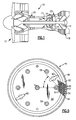
Figure 5 is a top elevational view of the fixture and shuttle shown inFigure 4 . -
Figure 6 is a cross-sectional view of the fixture removed from the shuttle. -
Figure 7 is an enlarged cross-sectional view of the bristles and plate during welding. -
Figure 8 is a schematic view of an example brush seal manufacturing process. - A
gas turbine engine 10 is schematically shown inFigure 1 . Theengine 10 includes alow spool 12 and ahigh spool 14 coaxial with one another for rotation about a common axis. Alow pressure compressor 16 andlow pressure turbine 18 are mounted on thelow spool 12. A highpressure compressor section 20 and a highpressure turbine section 22 are mounted on thehigh spool 14. Afan 13 is coupled to thelow spool 12. Thespools turbine sections case 11. Various rotating structures are sealed relative to thecase 11 withseals 24. One such commonly used seal is a brush seal. - Referring to
Figure 2 , abrush seal assembly 28 is housed within acarrier 26 and retained relative thereto by aretainer 30 and a shoulder of the carrier. Thebrush seal assembly 28 seals against a rotatingmember 32. Thebrush seal assembly 28 includesbristles 36 circumferentially arranged about an axis A (Figure 5 ). First andsecond plates bristles 36 to provide thebrush seal assembly 28. In the example brush seal manufacturing process, thebristles 36 are not secured to one another to provide a bristle assembly or hoop before securing the bristles to theplates bristles 36 are secured directly to at least oneplate - A
fixture 44 is used to securebristles 60 andplate 62 to one another in a desired diametrical and angular orientation so that they can be welded together. Referring toFigures 3-6 , abase 48 is temporarily positioned in ashuttle 46. Thebase 48 includesinner guides 54 that provide first bristle alignment features. Aninner diameter surface 67 of theshuttle 46 provides a second bristle alignment feature. Theshuttle 46 includesouter guides 56 that provide third bristle alignment features. Thebristles 60 are supported on abottom wall 52 of thebase 48. Theguides bristles 60 in a desired orientation relative to one another as they are circumferentially spaced about the axis A, best shown inFigure 5 . - Outer ends of the
bristles 60 provide anedge 64. In one example, theedges 64 of thebristles 60 are arranged to abut aninner diameter surface 67 of theshuttle 46. Aplate 62 is arranged adjacent thebristles 60 such that theplate 62 andbristles 64 are in engagement with one another. Theplate 62 includes a periphery orperimeter edge 66 that also abuts theinner diameter surface 67 of theshuttle 46. As a result, theedges 64 of thebristles 60 and theperimeter edge 66 of theplate 62 together provide aflush surface 68. That is, the outer ends (edges 64) of thebristles 60 run true to the outside diameter (perimeter edge 66) of theplate 62. As shown inFigure 7 , theedges 64 andperimeter edge 66 are coplanar at a plane P that is tangential to the periphery of theplate 62. Acover 50 is secured to thebase 48 byfasteners 58 to securely retain thebristles 60 andplate 62 relative to one another in the desired position. Thefixture 44 is removed from theshuttle 46 usingeyebolts 65, for example. - With the
fixture 44 removed from theshuttle 46, theflush surface 68 is exposed, as shown inFigures 6 and 7 . Thebristles 60 are welded to theplate 62 using awelder 70. In one example, thewelder 70 is a laser welder that generates aweld bead 72 securing thebristles 60 to theplate 62 with alaser beam 74. Theweld bead 72 generated with the laser welder is more precise and much smaller than a TIG generated weld bead, thus requiring less machining. - The example brush seal manufacturing method 76 is schematically shown in
Figure 8 . The method 76 includes aligning thebristles 60 andplate 62 to provide aflush surface 68, as described above, as schematically indicated at block 78. Thebristles 60 are welded to theplate 62, as indicated at block 80. If desired, multiple bristle and plate subassemblies can be arranged one on top of another to provide a multi-layered brush seal, as indicated at block 82. After welding, the brush seal assembly is machined at its periphery to achieve desired surface features and dimensions at theweld bead 72, as indicated at block 84. - Although example embodiments have been disclosed, a worker of ordinary skill in this art would recognize that certain modifications would come within the scope of the claims. For that reason, the following claims should be studied to determine their true scope and content.
Claims (15)
- A method of manufacturing a brush seal assembly (28) comprising the steps of:circumferentially arranging bristles (60) about an axis (A);arranging a plate (62) adjacent the bristles (60);aligning unwelded ends (64) of the bristles (60) with a periphery (66) of the plate (62) to provide a flush surface (68); andwelding the unwelded ends (64) to the periphery (66) at the flush surface (68) to provide a unitary subassembly.
- The method according to claim 1, wherein the unwelded ends include edges (64), the edges providing a flush surface (68) with the periphery (66), wherein, optionally, the periphery (66) includes a plane (P) tangential thereto, the edges (64) and the periphery (66) are coplanar with one another at the plane (P).
- The method according to claim 1 or 2, wherein the bristle arranging step includes spacing the bristles (60) relative to one another with guides (54,56) arranged between the bristles (60).
- The method according to claim 1, 2 or 3, wherein the bristle and plate arranging steps include providing a base (48) with inner guides (54) and a shuttle (46) with outer guides (56), the base (48) removable relative to the shuttle (46).
- The method according to claim 3 or 4, wherein the plate (62) is arranged over the guides (54,56).
- The method according to any preceding claim, wherein the welding step includes laser welding the flush surface (68).
- The method according to any preceding claim, wherein the periphery (66) is an outer periphery.
- The method according to any preceding claim, wherein the plate (62) and bristles (60) are arranged axially relative to one another, the plate (62) and bristles (60) in engagement with one another.
- A brush seal welding fixture (44) comprising:a base (48) having first bristle alignment features (54);a shuttle (46) configured to receive the base (48), the shuttle (46) having second bristle alignment features (67); anda cover (50) secured or for securing to the base (48) and configured to retain bristles (60) and a brush seal plate (62) in engagement with one another in a desired orientation, which includes providing a flush surface (68) between the bristles (60) and the brush seal plate (62).
- The fixture according to claim 9, wherein the second bristle alignment features comprise an inner diameter surface (67) configured to diametrically align the bristles (60) to the plate (62), and wherein, optionally, the inner diameter surface (67) aligns the plate (62) and the bristles (60) in the desired orientation.
- The fixture according to claim 9 or 10, wherein the plate (62) is generally annular in shape, and the bristles (60) are arranged in engagement axially relative to the plate (62).
- The fixture according to claim 11, comprising fasteners (58) for clamping the base (48) and cover (50) to one another to retain the bristles (60) and plate (62) in engagement with one another.
- The fixture according to any of claims 9 to 12, wherein the first bristle alignment features include guide pins (54) extending from a bottom wall (52) of the base (48).
- The fixture according to any of claims 9 to 13, wherein the shuttle (46) comprises third bristle alignment features (56) configured to position the bristles (60) in the desired orientation, the third bristle alignment features comprising, for example, guides (56) arranged between the bristles (60).
- The fixture according to any of claims 9 to 14, comprising a laser welder (70) arranged in proximity to the bristles (60) and plate (62) configured to weld the bristles (60) and plate (62) to one another at the flush surface (68).
Priority Applications (1)
| Application Number | Priority Date | Filing Date | Title |
|---|---|---|---|
| EP13150518.2A EP2586329B1 (en) | 2008-03-03 | 2009-02-27 | Bristle and plate subassembly fixing apparatus |
Applications Claiming Priority (1)
| Application Number | Priority Date | Filing Date | Title |
|---|---|---|---|
| US12/041,031 US8528178B2 (en) | 2008-03-03 | 2008-03-03 | Bristle and plate subassembly fixture and manufacturing method |
Related Child Applications (2)
| Application Number | Title | Priority Date | Filing Date |
|---|---|---|---|
| EP13150518.2A Division-Into EP2586329B1 (en) | 2008-03-03 | 2009-02-27 | Bristle and plate subassembly fixing apparatus |
| EP13150518.2A Division EP2586329B1 (en) | 2008-03-03 | 2009-02-27 | Bristle and plate subassembly fixing apparatus |
Publications (2)
| Publication Number | Publication Date |
|---|---|
| EP2098133A1 true EP2098133A1 (en) | 2009-09-09 |
| EP2098133B1 EP2098133B1 (en) | 2014-06-04 |
Family
ID=40718910
Family Applications (2)
| Application Number | Title | Priority Date | Filing Date |
|---|---|---|---|
| EP09250560.1A Active EP2098133B1 (en) | 2008-03-03 | 2009-02-27 | Bristle and plate subassembly fixture and manufacturing method |
| EP13150518.2A Active EP2586329B1 (en) | 2008-03-03 | 2009-02-27 | Bristle and plate subassembly fixing apparatus |
Family Applications After (1)
| Application Number | Title | Priority Date | Filing Date |
|---|---|---|---|
| EP13150518.2A Active EP2586329B1 (en) | 2008-03-03 | 2009-02-27 | Bristle and plate subassembly fixing apparatus |
Country Status (2)
| Country | Link |
|---|---|
| US (1) | US8528178B2 (en) |
| EP (2) | EP2098133B1 (en) |
Families Citing this family (4)
| Publication number | Priority date | Publication date | Assignee | Title |
|---|---|---|---|---|
| US8528178B2 (en) * | 2008-03-03 | 2013-09-10 | United Technologies Corporation | Bristle and plate subassembly fixture and manufacturing method |
| WO2014014426A2 (en) | 2012-06-28 | 2014-01-23 | Sdm Siradişi Arge Ve Mühendi̇sli̇k Sanayi̇ Ti̇caret Li̇mi̇ted Şi̇rketi̇ | Brush seal for high pressure applications |
| US9863538B2 (en) | 2015-04-27 | 2018-01-09 | United Technologies Corporation | Gas turbine engine brush seal with supported tip |
| US11553780B2 (en) | 2017-07-12 | 2023-01-17 | Koninklijke Philips N.V. | Brush head manufacturing method |
Citations (4)
| Publication number | Priority date | Publication date | Assignee | Title |
|---|---|---|---|---|
| GB2022197A (en) * | 1978-05-31 | 1979-12-12 | Cross Mfg Co | Brush seals and methods of manufacture thereof |
| US4678113A (en) * | 1985-02-20 | 1987-07-07 | Rolls-Royce Plc | Brush seals |
| US4989919A (en) | 1988-08-30 | 1991-02-05 | Pratt & Whitney Canada | Method and apparatus for manufacturing compliant brush seals |
| EP1335157A2 (en) | 2002-02-12 | 2003-08-13 | United Technologies Corporation | Bristle arrangement for brush seal, method and assembly for making same, and method of making brush seal |
Family Cites Families (13)
| Publication number | Priority date | Publication date | Assignee | Title |
|---|---|---|---|---|
| US4884850A (en) * | 1988-08-30 | 1989-12-05 | Pratt & Whitney Canada, Inc. | Method and apparatus for manufacturing compliant brush seals |
| US7181843B1 (en) * | 1995-09-28 | 2007-02-27 | United Technologies Corporation | Method of manufacturing a brush seal |
| US5639211A (en) * | 1995-11-30 | 1997-06-17 | United Technology Corporation | Brush seal for stator of a gas turbine engine case |
| US5776389A (en) * | 1996-06-20 | 1998-07-07 | The Dow Chemical Company | Process for making an alkenyl aromatic polymer foam having enlarged cell size |
| US6390476B1 (en) * | 2000-09-08 | 2002-05-21 | General Electric Company | Heat-resistant magnetic silicone rubber brush seals in turbomachinery and methods of application |
| JP4751552B2 (en) * | 2001-09-28 | 2011-08-17 | イーグル工業株式会社 | Plate brush seal and plate brush seal device |
| JP4675530B2 (en) * | 2001-09-28 | 2011-04-27 | イーグル工業株式会社 | Plate brush seal |
| US7931276B2 (en) * | 2002-03-20 | 2011-04-26 | United Technologies Corporation | Brush seal |
| US7270333B2 (en) * | 2002-11-27 | 2007-09-18 | United Technologies Corporation | Brush seal with adjustable clearance |
| US7000923B2 (en) * | 2004-01-09 | 2006-02-21 | United Technologies Corporation | Quick build brush seals |
| US7226054B2 (en) * | 2004-12-14 | 2007-06-05 | United Technologies Corporation | Clamp lock brush seal assembly |
| US7565729B2 (en) * | 2006-03-17 | 2009-07-28 | General Electric Company | Methods of manufacturing a segmented brush seal for sealing between stationary and rotary components |
| US8528178B2 (en) * | 2008-03-03 | 2013-09-10 | United Technologies Corporation | Bristle and plate subassembly fixture and manufacturing method |
-
2008
- 2008-03-03 US US12/041,031 patent/US8528178B2/en active Active
-
2009
- 2009-02-27 EP EP09250560.1A patent/EP2098133B1/en active Active
- 2009-02-27 EP EP13150518.2A patent/EP2586329B1/en active Active
Patent Citations (4)
| Publication number | Priority date | Publication date | Assignee | Title |
|---|---|---|---|---|
| GB2022197A (en) * | 1978-05-31 | 1979-12-12 | Cross Mfg Co | Brush seals and methods of manufacture thereof |
| US4678113A (en) * | 1985-02-20 | 1987-07-07 | Rolls-Royce Plc | Brush seals |
| US4989919A (en) | 1988-08-30 | 1991-02-05 | Pratt & Whitney Canada | Method and apparatus for manufacturing compliant brush seals |
| EP1335157A2 (en) | 2002-02-12 | 2003-08-13 | United Technologies Corporation | Bristle arrangement for brush seal, method and assembly for making same, and method of making brush seal |
Also Published As
| Publication number | Publication date |
|---|---|
| US8528178B2 (en) | 2013-09-10 |
| EP2098133B1 (en) | 2014-06-04 |
| US20090218771A1 (en) | 2009-09-03 |
| EP2586329A1 (en) | 2013-05-01 |
| EP2586329B1 (en) | 2021-05-19 |
Similar Documents
| Publication | Publication Date | Title |
|---|---|---|
| US6722555B2 (en) | Friction stir welding method | |
| JP5061098B2 (en) | Friction stir welding method | |
| EP3100817B1 (en) | Friction stir welding method | |
| JP2008110404A (en) | Method and apparatus for repairing aperture and adjacent defect in flange | |
| US8528178B2 (en) | Bristle and plate subassembly fixture and manufacturing method | |
| US6607114B2 (en) | Weld fixture and method for repairing annular components | |
| JPH09500188A (en) | Combustion chamber assembly repair method | |
| KR20180115936A (en) | method for manufacturing brush seal | |
| US4079491A (en) | Method and apparatus for forming a valve seat by inertia welding | |
| US6754956B1 (en) | Methods for manufacturing a nozzle box assembly for a steam turbine | |
| JP2007111716A (en) | Clamping device, joining device and joining method | |
| EP2208569B1 (en) | Repair of case flange with bolt holes | |
| US7507933B2 (en) | Method for fabricating a rotor shaft | |
| JPH09500189A (en) | Combustion chamber assembly repair equipment | |
| JP2005034894A (en) | Positioning fixture for butt welding of piping | |
| EP2327505A2 (en) | Welding repair method | |
| EP1391881A2 (en) | Pivot assembly for hard disk drive use | |
| JP2005282184A (en) | Joint for metallic cylindrical material such as steel pipe for pile | |
| GB2286142A (en) | Energy beam butt welding of forged and cast metal | |
| US12311479B2 (en) | Weld root gap management apparatus | |
| CN216263971U (en) | Argon arc that can guarantee axiality welds uses frock | |
| JP3556861B2 (en) | Sealing device, jig for manufacturing the same, and method for manufacturing the same | |
| CN109079448A (en) | A kind of strengthening groove coil structures and its processing technology | |
| KR20010076270A (en) | Welding construction | |
| KR101537017B1 (en) | Manufacture methods of sponge having a spiral incision line for sectionally purging of pipe |
Legal Events
| Date | Code | Title | Description |
|---|---|---|---|
| PUAI | Public reference made under article 153(3) epc to a published international application that has entered the european phase |
Free format text: ORIGINAL CODE: 0009012 |
|
| AK | Designated contracting states |
Kind code of ref document: A1 Designated state(s): AT BE BG CH CY CZ DE DK EE ES FI FR GB GR HR HU IE IS IT LI LT LU LV MC MK MT NL NO PL PT RO SE SI SK TR |
|
| AX | Request for extension of the european patent |
Extension state: AL BA RS |
|
| 17P | Request for examination filed |
Effective date: 20091002 |
|
| 17Q | First examination report despatched |
Effective date: 20091028 |
|
| AKX | Designation fees paid |
Designated state(s): DE GB |
|
| GRAP | Despatch of communication of intention to grant a patent |
Free format text: ORIGINAL CODE: EPIDOSNIGR1 |
|
| INTG | Intention to grant announced |
Effective date: 20131219 |
|
| GRAS | Grant fee paid |
Free format text: ORIGINAL CODE: EPIDOSNIGR3 |
|
| GRAA | (expected) grant |
Free format text: ORIGINAL CODE: 0009210 |
|
| AK | Designated contracting states |
Kind code of ref document: B1 Designated state(s): DE GB |
|
| REG | Reference to a national code |
Ref country code: GB Ref legal event code: FG4D |
|
| REG | Reference to a national code |
Ref country code: DE Ref legal event code: R096 Ref document number: 602009024412 Country of ref document: DE Effective date: 20140717 |
|
| REG | Reference to a national code |
Ref country code: DE Ref legal event code: R097 Ref document number: 602009024412 Country of ref document: DE |
|
| PLBE | No opposition filed within time limit |
Free format text: ORIGINAL CODE: 0009261 |
|
| STAA | Information on the status of an ep patent application or granted ep patent |
Free format text: STATUS: NO OPPOSITION FILED WITHIN TIME LIMIT |
|
| 26N | No opposition filed |
Effective date: 20150305 |
|
| REG | Reference to a national code |
Ref country code: DE Ref legal event code: R097 Ref document number: 602009024412 Country of ref document: DE Effective date: 20150305 |
|
| REG | Reference to a national code |
Ref country code: DE Ref legal event code: R082 Ref document number: 602009024412 Country of ref document: DE Representative=s name: SCHMITT-NILSON SCHRAUD WAIBEL WOHLFROM PATENTA, DE |
|
| REG | Reference to a national code |
Ref country code: DE Ref legal event code: R082 Ref document number: 602009024412 Country of ref document: DE Representative=s name: SCHMITT-NILSON SCHRAUD WAIBEL WOHLFROM PATENTA, DE Ref country code: DE Ref legal event code: R081 Ref document number: 602009024412 Country of ref document: DE Owner name: UNITED TECHNOLOGIES CORP. (N.D.GES.D. STAATES , US Free format text: FORMER OWNER: UNITED TECHNOLOGIES CORP., HARTFORD, CONN., US |
|
| REG | Reference to a national code |
Ref country code: DE Ref legal event code: R081 Ref document number: 602009024412 Country of ref document: DE Owner name: RAYTHEON TECHNOLOGIES CORPORATION (N.D.GES.D.S, US Free format text: FORMER OWNER: UNITED TECHNOLOGIES CORP. (N.D.GES.D. STAATES DELAWARE), FARMINGTON, CONN., US Ref country code: DE Ref legal event code: R081 Ref document number: 602009024412 Country of ref document: DE Owner name: RTX CORPORATION (N.D.GES.D. STAATES DELAWARE),, US Free format text: FORMER OWNER: UNITED TECHNOLOGIES CORP. (N.D.GES.D. STAATES DELAWARE), FARMINGTON, CONN., US |
|
| P01 | Opt-out of the competence of the unified patent court (upc) registered |
Effective date: 20230519 |
|
| REG | Reference to a national code |
Ref country code: DE Ref legal event code: R081 Ref document number: 602009024412 Country of ref document: DE Owner name: RTX CORPORATION (N.D.GES.D. STAATES DELAWARE),, US Free format text: FORMER OWNER: RAYTHEON TECHNOLOGIES CORPORATION (N.D.GES.D.STAATES DELAWARE), ARLINGTON, VA, US |
|
| PGFP | Annual fee paid to national office [announced via postgrant information from national office to epo] |
Ref country code: GB Payment date: 20260121 Year of fee payment: 18 |
|
| PGFP | Annual fee paid to national office [announced via postgrant information from national office to epo] |
Ref country code: DE Payment date: 20260121 Year of fee payment: 18 |