EP2098018B1 - Communication system having a master/slave structure - Google Patents
Communication system having a master/slave structure Download PDFInfo
- Publication number
- EP2098018B1 EP2098018B1 EP07847359.2A EP07847359A EP2098018B1 EP 2098018 B1 EP2098018 B1 EP 2098018B1 EP 07847359 A EP07847359 A EP 07847359A EP 2098018 B1 EP2098018 B1 EP 2098018B1
- Authority
- EP
- European Patent Office
- Prior art keywords
- unit
- master
- slave
- master unit
- communication path
- Prior art date
- Legal status (The legal status is an assumption and is not a legal conclusion. Google has not performed a legal analysis and makes no representation as to the accuracy of the status listed.)
- Active
Links
- 238000004891 communication Methods 0.000 title claims description 149
- 230000005540 biological transmission Effects 0.000 claims description 115
- 238000010168 coupling process Methods 0.000 claims description 55
- 238000005859 coupling reaction Methods 0.000 claims description 55
- 230000008878 coupling Effects 0.000 claims description 54
- 230000009977 dual effect Effects 0.000 claims description 9
- 238000012545 processing Methods 0.000 description 7
- 238000012546 transfer Methods 0.000 description 6
- 238000004519 manufacturing process Methods 0.000 description 4
- 238000013475 authorization Methods 0.000 description 3
- 238000010586 diagram Methods 0.000 description 3
- 238000011156 evaluation Methods 0.000 description 3
- 238000000034 method Methods 0.000 description 3
- 230000002093 peripheral effect Effects 0.000 description 3
- 238000005516 engineering process Methods 0.000 description 2
- 230000001960 triggered effect Effects 0.000 description 2
- 238000012800 visualization Methods 0.000 description 2
- 238000013075 data extraction Methods 0.000 description 1
- 230000006735 deficit Effects 0.000 description 1
- 230000001419 dependent effect Effects 0.000 description 1
- 238000013461 design Methods 0.000 description 1
- 239000000835 fiber Substances 0.000 description 1
- 238000012423 maintenance Methods 0.000 description 1
- 239000002674 ointment Substances 0.000 description 1
- 238000004801 process automation Methods 0.000 description 1
- 238000004886 process control Methods 0.000 description 1
Images


Classifications
-
- H—ELECTRICITY
- H04—ELECTRIC COMMUNICATION TECHNIQUE
- H04L—TRANSMISSION OF DIGITAL INFORMATION, e.g. TELEGRAPHIC COMMUNICATION
- H04L12/00—Data switching networks
- H04L12/28—Data switching networks characterised by path configuration, e.g. LAN [Local Area Networks] or WAN [Wide Area Networks]
- H04L12/42—Loop networks
- H04L12/437—Ring fault isolation or reconfiguration
-
- H—ELECTRICITY
- H04—ELECTRIC COMMUNICATION TECHNIQUE
- H04L—TRANSMISSION OF DIGITAL INFORMATION, e.g. TELEGRAPHIC COMMUNICATION
- H04L12/00—Data switching networks
- H04L12/28—Data switching networks characterised by path configuration, e.g. LAN [Local Area Networks] or WAN [Wide Area Networks]
- H04L12/40—Bus networks
- H04L12/40169—Flexible bus arrangements
- H04L12/40176—Flexible bus arrangements involving redundancy
- H04L12/40202—Flexible bus arrangements involving redundancy by using a plurality of master stations
Definitions
- the invention relates to a communication system with a master-slave structure and a master unit for such a communication system.
- serial bus systems are increasingly being used in which the decentralized devices of a machine periphery such as I / O modules, transducers, drives, valves and operator terminals communicate via an efficient real-time communication system with automation, engineering or visualization systems. All subscribers are networked with each other via a serial bus, preferably via a field bus, wherein the data exchange over the bus is usually carried out on the basis of the master-slave principle.
- the active bus subscribers on the bus system usually controllers, are in possession of a bus access authorization and determine the data transfer on the bus.
- the active bus users are referred to below as the master units in the serial bus system.
- Passive bus users are usually machine peripherals. You do not receive bus access authorization, i. they may acknowledge only received information signals or transmit information signals to a master unit on request.
- the passive bus users are referred to below as slave units in the serial bus system.
- Field bus systems with a master-slave structure are generally implemented in ring topology, in order to avoid complicated wiring, with all bus users being connected to an annular transmission path.
- An information signal generated by the master unit is fed from the master unit into the annular transmission path and successively traverses the slave units serially connected to the annular transmission path, and then again to be received and evaluated by the master unit.
- the information signals are organized by the master unit usually in data packets, which are composed of control data and payload, preferably using the Ethernet standard, the data packets with a length of up to 1500 bytes at a high transmission speed of 100 Mbit / sec allows.
- Each of the slave units connected to the annular transmission path then processes the user data intended for it for the Ethernet telegrams fed in by the master unit on the ring-shaped transmission path.
- the master-slave communication systems with ring structure are usually constructed so that the master unit has a transmitting unit as a data input point and a receiving unit as a data extraction point.
- the individual slave units are then combined on the transmission path to a ring, each participant is connected to two neighbors, the first and the last participant in the ring with the master unit.
- the transmission of the data packets takes place in one direction, starting from the master unit via its transmitting unit to the first connected slave unit and from there to the next, until the data transmission direction last slave unit is reached in the ring, and then back to the receiving unit of the master unit.
- Each slave unit has a first connection for receiving the circulating data packets from the previous user and a second connection for forwarding to the subsequent user, a processing device being arranged between the two connections in order to process the data packets passing through the slave unit.
- Errors in the communication system which must be overcome without impairment, are in addition to errors in the data packets and the failure of a subscriber in particular the master unit in the transmission path or an interruption of the transmission path, for example by physical severing of the transmission medium.
- a master-slave communication system with two master nodes to compensate for the failure of a master node, and a double-line structure to be able to switch on an interruption between the lines, is known from US Pat US 2004/0008720 A1 known.
- a similar system is in the US 2005/0129037 A1 described.
- US 2003/0005368 A1 is a ring communication system having a dual ring structure in which the nodes have a switching function to maintain communication on the ring network when the line structure is broken.
- the WO 91/14324 A discloses a master unit and a communication system having a dual ring structure and a plurality of master units, the master units and the slave units each having switching units which monitor the data transmission in the ring network. In the master units, the switching devices communicates constantly with their control units.
- the object of the present invention is to provide a communication system with a master-slave structure and a master unit for such a communication system, which with minimal hardware and switching overhead, the possibility of reconfiguration of the master-slave structure in real time in an interruption of the transmission path, especially in case of failure of the master unit allow.
- a first and a second master unit and at least one slave unit connected by a double line structure Each of the first and second master units has a transmitting unit for transmitting data signals connected to the double line structure via first terminals, a receiving unit for receiving data signals connected to the double line structure via second terminals, and a control unit for transmitting Data signals that are connected to the transmitting units and the receiving units on.
- the second master unit further comprises a master coupling device which is connected between the control unit, the receiving unit and the transmitting unit in order to separate the control unit from the receiving unit and the transmitting unit in a first operating mode upon receipt of data signals of the first master unit on the double line structure and in a second operation mode, upon interruption of the reception of data signals of the first master unit on the double line structure, the control unit is connected to the reception unit and the transmission unit to perform data transmission on the double line structure.
- a master coupling device which is connected between the control unit, the receiving unit and the transmitting unit in order to separate the control unit from the receiving unit and the transmitting unit in a first operating mode upon receipt of data signals of the first master unit on the double line structure and in a second operation mode, upon interruption of the reception of data signals of the first master unit on the double line structure, the control unit is connected to the reception unit and the transmission unit to perform data transmission on the double line structure.
- the second substitute master unit is connected in the data transmission chain from the first regular master unit to the slave units in order to continue the data transmission when a route error occurs, in particular in the event of failure of the first regular master unit.
- a master unit according to the invention for use as a replacement master unit has a transmitting unit for transmitting data signals, which can be connected via a first connection to a first communication path, a receiving unit for receiving data signals, which can be connected to a communication path via a second connection, and a control unit for transmitting data signals and a master coupling device.
- the master coupling device is connected between the control unit, the transmitting unit and the receiving unit in order to a first operating mode, ie in normal operation, to separate the control unit from the receiving unit and the transmitting unit and to connect the control unit to the receiving unit and the transmitting unit in a second operating mode, ie in route error operation, to transfer data on the first and the second communication path perform.
- the data transmission path is automatically reconfigured in such a way that the replacement master unit takes over the data transmission in the part of the master-slave communication system which is separated from the regular master unit.
- the first and second master units are provided in the communication system, between which the at least one slave unit is arranged.
- the slave unit has a slave coupling device and a first, second, third and fourth connection.
- the first terminal of the slave unit is connected to the transmitting unit of the first master unit and the second terminal of the slave unit to the receiving unit of the second master unit via a first communication path of the double line structure.
- the third connection of the slave unit is connected to the transmission unit of the second master unit and the fourth connection of the slave unit to the reception unit of the first master unit via a second communication path of the double line structure.
- the master coupling device of the second master unit In the first operating mode, ie in normal operation, the master coupling device of the second master unit short-circuits the first connection connected to the transmission unit and the second connection of the second master unit connected to the reception unit, and the data transmission takes place exclusively through the first master unit.
- the slave coupling device of the slave unit In the second operating mode, ie when a path error occurs, the slave coupling device of the slave unit short-circuits the first connection of the slave unit to the fourth connection of the slave unit.
- the master coupling device of the second master unit for data transmission on the first and second communication paths opens the short circuit of the first and second terminals of the second master unit and connects the control unit with the transmitting unit and the receiving unit for data transmission operation.
- the master coupling device in the first operating mode, short-circuits the first terminal connected to the transmitting unit and the second terminal connected to the receiving unit and, in the second operating mode, removes the short circuit from the first and second terminals.
- the slave unit has at least one first, second and third connection, wherein the first connection of the slave unit with the transmission unit of the first master unit and the second connection of the slave unit with the reception unit of the second master unit via a first communication path of the double line structure are connected.
- the third terminal of the slave unit is connected to the transmitting unit of the second master unit via a second communication path of the double line structure, and a third terminal of the second master unit is connected to the receiving unit of the first master unit via a third communication path of the double line structure.
- the master coupling device of the second master unit short-circuits the second terminal connected to the receiving unit and the third terminal of the second master unit, and the data is transferred from the first master unit via the first and third communication paths.
- the slave coupling device of the slave unit short-circuits the first terminal of the slave unit to the fourth terminal of the slave unit and the master-coupling unit of the second master unit removes the short circuit of the second and third terminals for data transmission on the first and second communication paths second master unit and connects the control unit with the transmitting unit and the receiving unit for data transmission operation.
- a third connection which can be connected to a third communication path is provided.
- the master coupling device In the first operating mode, the master coupling device then briefly closes the second terminal connected to the receiving unit and the third terminal and, in the second operating mode, releases the short circuit from the second and third terminal.
- the slave unit has a first and a second connection, the first connection of the slave unit to the reception unit of the second master unit via a first communication path of the double-line structure, the second connection of the slave unit to the transmission unit of the second master unit via a second communication path the double line structure, a third terminal of the second master unit are connected to the receiving unit of the first master unit via a third communication path of the double line structure and a fourth terminal of the second master unit to the transmitting unit of the first master unit via a fourth communication path of the double line structure.
- the master coupling device of the second master unit short-circuits each of the first terminal connected to the transmitting unit and the fourth terminal of the second master unit and the second terminal connected to the receiving unit and the third terminal of the second master unit and the data transmission takes place exclusively through the first master unit.
- the master coupling device of the second master unit for data transmission on the first and second communication path, the short circuit of the first and fourth terminals of the second master unit and the short circuit of the second and third terminals of the second master unit and connects the control unit with the transmitting unit and the receiving unit for data transmission operation.
- a third connection which can be connected to a third communication path and a fourth connection which can be connected to a fourth communication path are provided.
- the master coupling device short-circuits the second and the third connection and the first the fourth connection and, in the second operating mode, releases the short circuit from the second and third connection as well as from the first and fourth connection.
- the transmission path is designed as a physical line with a double-line structure, the slave unit each having two ports each having two terminals to which the double-line structure is connected.
- the transmission chain is terminated on one side by the regular master unit and on the other side by the replacement master unit.
- the regular master unit transmits and receives over the dual-line structure, with the spare master unit serving as a line terminator over which the dual line is shorted to feed back the data packets arriving from the regular master unit on the first line to the regular master unit. If a route error occurs, in particular if the regular master unit fails, the slave unit briefly closes its port coupled to the regular master unit.
- the master coupling device opens the replacement master unit the internal short circuit and connects the one first control line of the control unit to the transmitting unit and another second control line of the control unit to the receiving unit to receive the data transmission.
- the master-slave communication system is formed as a ring structure, wherein the replacement master unit is arranged in the data transfer direction in the normal direction in front of the receiving unit of the regular master unit to feed back the transmitted data packets to the regular master unit.
- the master coupling device opens this short circuit and connects the transmitting unit and the receiving unit to the control unit to record the data transmission.
- the master-slave communication system is designed as a ring structure, wherein the replacement master unit is arranged in the normal data transfer direction between the slave units and the regular master unit to pass through the data packets of the regular master unit.
- the master coupling device opens these short circuits and connects the control unit with the transmitting unit and the receiving unit to record the data transmission.
- the data transmission path is automatically reconfigured such that the replacement master unit transmits the data in the part of the master-slave communication system separated from the regular master unit.
- the data transmission path is automatically reconfigured in such a way that the replacement master unit takes over the data transmission in the part of the master-slave communication system which is separated from the regular master unit.
- the Fieldbus system usually has a serial bus, which may be, for example, an electrical line, a light guide or a radio cable. All bus subscribers are connected to this fieldbus, whereby a distinction is made between active and passive bus subscribers.
- the active bus users on the fieldbus system are the master units that control the traffic on the bus.
- a master unit is e.g. an industrial PC that serves as a process control computer in a production line.
- the master unit has bus access authority and can output data without external request on the fieldbus.
- the passive bus users on the bus system are the machine peripherals such. I / O devices, valves, drives and transducers. They serve as slave units and have no bus access authorization, i. they may only acknowledge received data signals or, on request, transmit data signals to a master unit via them.
- the Ethernet concept is preferably used.
- the data to be transmitted are encapsulated in the form of data packets, also referred to as telegrams, in a predefined format.
- the Ethernet telegram can have a data length of up to 1000 bytes, wherein in addition to the user data control data, which have an initial identifier, a destination and source address and a data packet type and an error mechanism are included.
- Ethernet communication systems with a master-slave structure are preferably designed so that the individual master units are connected to form a chain via the transmission medium, wherein each slave unit with two neighbors, the first and the last slave unit in the chain are connected to the master unit so that a ring structure results.
- the data transfer takes place in one Direction from the master unit to the first adjacent slave unit and from there to the next to the last slave unit and then back to the master unit.
- a replacement master unit is provided in the master-slave communication system in addition to the regular master unit.
- Fig. 1 shows a schematic diagram of a first embodiment of such a fault-tolerant master-slave communication system, wherein Fig. 1A the normal operation, in which the data exchange is performed by the regular master unit, and Fig. 1B represent a reconfiguration operation in case of failure of the regular master unit and data transmission through the replacement master unit.
- the master-slave communication system has a first master unit 1, hereinafter also referred to as main master unit, and a second master unit 2, also referred to as a replacement master unit, between which N slave units 3 are connected.
- the main master unit 1 and the replacement master unit 2 are connected via a double line structure 4 with the N slave units 3.
- the double-line structure comprises two separate transmission paths, each of which forms an independent communication path 41, 42. As transmission can serve an electrical line, a fiber optic cable or a radio cable.
- the main master unit 1 has a transmitting unit TX 11 and a receiving unit RX 12.
- the transmitting unit TX 11 is connected via a first terminal 111 to one end of the first communication path 41 and the receiving unit RX 12 via a second terminal 112 to one end of the second communication path 42.
- the master unit 1 contains a control unit 13, which via control lines 14 at the transmitting unit TX 11 and the receiving unit RX 12 is connected.
- the replacement master unit 2 has a receiving unit RX 21 and a transmitting unit TX 22.
- the receiving unit RX 21 is connected via a first terminal 221 to the second end of the first communication path 41 and the transmitting unit TX 22 via a second terminal 222 to the second end of the second communication path 42.
- the replacement master unit 2 further comprises a master coupling device 23, which is connected between a control unit 24 and its control lines 25 and the receiving unit RX 21 and the transmitting unit TX 22.
- Each slave unit 3 has a first connection with a first reception unit RX 31 for receiving the data packets from a previous participant via the first communication path 41 and a second connection with a first transmission unit TX 32 via the first communication path 41 for forwarding to the next participant. Furthermore, each slave unit 3 has a third connection with a second reception unit RX 33 for receiving the data packets via the second communication path 42 from a previous subscriber and a fourth connection with a second transmission unit TX 34 for forwarding via the second communication path 42 to the following subscriber.
- the first receiving unit RX 31 of the slave unit 3, which is connected to the first communication path 41, and the second transmitting unit TX 34, which is connected to the second communication path 42, are combined to form a common port 0.
- the second receiving unit RX 33 which is connected to the second communication path 42, and the transmitting unit TX 32, which are connected to the first communication path 41, are combined to form a common port 1.
- a processing unit 35 is connected in the first communication path 41.
- the second communication path 42 is through the slave unit 3 is looped through by the receiving unit RX 33 to the transmitting unit TX 34.
- the slave unit adjacent to the main master unit 1 furthermore has, in the port 0 connected to the main master unit 1, a coupling device 36 which is connected between the first receiving unit RX 31 and the second transmitting unit TX 34.
- Fig. 1A shows the trouble-free normal operation of the master-slave communication system.
- the direction of the data transmission on the lines 14, 25 in the master or slave units and on the communication paths 41, 42 is indicated as an arrow, with the lines and transmission paths used for the data transmission in each case being highlighted.
- a data packet generated by the central control unit 13 of the main master unit 1 is output to the first communication path 41 via the transmitting unit TX 11 and the first terminal 111.
- the telegram is then received by the first connected slave unit 3 by the first receiving unit RX 31 in port 0 and forwarded via the processing unit 35 contained in the slave unit 3 to the first transmitting unit TX 32 in port 1, wherein the data packet from the processing unit 35 of the slave unit 3 is processed in the pass.
- the first transmission unit TX 32 in the port 1 of the slave unit 3 then sends the data packet to the first communication path 41 to the slave unit 3 next in the data transmission direction.
- the data packet in this way successively passes through all the slave units 3 connected to the first communication path 41 and is transmitted from the last slave unit 3 to the first communication path 41 via the first connection 221 to the reception unit RX 21 of the replacement master unit 2.
- the master coupling device 23 of the replacement master unit 2 short-circuits the receiving unit RX 21 and the transmitting unit TX 22 via the control lines 25 and the transmitting unit TX 22 of the substitute master unit 2 couples the data packet via the terminal 222 back to the second communication path 42.
- the data packet then passes through, as on the way out, on the way back in the data transmission direction successively connected to the second communication path 42 slave units 3, starting from the slave unit N to the slave unit 1, wherein the data packet is looped through unprocessed by the slave units 3.
- the last slave unit in the data transmission direction on the second communication path 42 then sends the data packet through the second transmitting unit TX 34 in port 0 via the second port 112 of the main master unit 1 to the receiving unit RX 12, from where the data packet is then forwarded to the central control unit 13 ,
- Fig. 1B shows the course of data transmission in the master-slave communication system in case of failure of the main master unit 1.
- the port 0 of the slave unit 3 adjoining the main master unit can determine by means of a recognition method whether it is possible to communicate with the main master unit 1 via the two communication paths 41, 42.
- the slave link unit 36 initiates the link error operation of the slave unit 3.
- the slave coupling device 36 then closes the connection of the first receiving unit RX 31 to the first communication path 41 and the connection of the second transmitting unit TX 34 to the second communication path 42. At the same time, the slave coupling device 36 connects the first communication path 41 with the second communication path 42.
- the replacement master unit 2 begins with the data transmission.
- the recording of the path error operation of the replacement master unit 2 is triggered by the master coupling device 23, which detects a timeout of the data transmission on the first communication path 41 due to the failure of the main master unit 1.
- the master coupling device 23 then removes the short circuit between the transmitting unit TX 22 and the receiving unit RX 21 and opens the line connection between the central control unit 24 and the transmitting unit TX 22 and the receiving unit RX 21 via the control lines 25.
- the control unit 24 determines the opening of the control lines 25 and then automatically starts the transmission operation in that the control unit 24 outputs a data packet generated by it via the transmission unit TX 22 and the second connection 222 to the second communication path 42.
- the data packet then passes through all the slave units 3 connected to it on the second communication path 42 in succession.
- the data packet has reached the slave unit 3 adjoining the failed main master unit 1 and running in route error mode, it is diverted from the second communication path 42 to the first communication path 41 via the short circuit generated in the slave unit 3 by the slave coupling device 36 on the way back the processing unit 35 is traversed in the slave unit 3 located in the route error mode.
- the data packet is then forwarded from the slave unit 3 located in the route error mode to the slave unit 3 adjacent to the first communication path 41 in the data transmission direction and from there to the next slave unit 3 until the data packet is fed back via the terminal 221 to the receiving unit RX 21 of the replacement master unit 2 is that passes on the received data packet via the control line 25 to the control unit 24 for evaluation.
- the reconfigured data transmission path is in Fig. 1B highlighted and the data transfer direction is indicated by arrows.
- the adjacent slave units can then each close the adjacent to the route error port and connect the first communication path 41 with the second communication path 42.
- the data transmission can then be carried out in two parts, with the slave units 3 being supplied with data packets on one side to the slave unit adjacent to the route error via the main master unit 1.
- other data transmission side transmits and receives the replacement master unit 2. It is thus possible to maintain the data transmission not only in case of failure of the main master unit, but also in the occurrence of a path error by reconfiguration of the data transmission paths using both master units.
- Fig. 2 shows a second embodiment of a master-slave communication system according to the invention, which performs a reconfiguration operation in case of failure of the main master unit.
- the main master unit 1 and the slave units 3 according to their structure in the Fig. 1 represented units.
- the replacement master unit 200 has, in addition to the in Fig. 1 a third connection 223 arranged thereon with a second transmitting unit TX 26, wherein a master coupling device 230 between control lines 250 of the control unit 24, the receiving unit RX 21, the first transmitting unit TX 22 and the second transmitting unit TX 26 connected is.
- the second transmitting unit TX 26 is connected to the receiving unit RX 12 of the main master unit 1 via a separate third master communication path 43.
- Fig. 2A shows the normal operation in data transmission by the main master unit 1 and Fig. 2B the reconfiguration operation in case of failure of the main master unit 1 and transmission mode by the replacement master unit 200.
- the data transmission takes place starting from the transmitting unit TX 11 of the main master unit 1 via the first slave communication path 41, wherein all serially connected slave units 3 are traversed with their processing units 35.
- the data packet is then forwarded from the last slave unit via the first port 221 to the receiving unit RX 21 of the spare master unit 200.
- the master coupling device 230 of the spare master unit shorted the receiving unit RX 21 to the second transmitting unit TX 26, so that the data packet from the second transmitting unit TX 26 via the third terminal 223 and the third master communication line 43 to the second terminal 112 and the receiving unit RX 12 of the main master unit 1 is fed back.
- the second slave communication path 42 is not used in normal operation and serves only as a replacement communication path when a path error occurs, in particular in the case of failure of the main master unit 1, as in Fig. 2B is shown.
- the slave coupling device 36 of the slave unit 1 connects the first communication path 41 to the second communication path 42.
- the master coupling device 230 of the replacement master unit 200 establishes a connection of the central control unit 24 with the first transmission unit TX 22 and the first reception unit RX 21, interrupts the connection existing in normal operation between the first reception unit RX 21 and the second transmission unit TX 26 and closes the third terminal 223 to the third master communication path 43.
- the transmission mode by the replacement master unit 200 is then analogous to the in Fig. 1B transmission mode shown, in which the data packet is forwarded from the replacement master unit 200 via the second communication path 42 to the master unit 1 adjacent to the slave unit 3 and then fed back via the first communication path 41 to the receiving unit RX 21 of the replacement master unit 200 ,
- the data transmission is carried out in two parts, the slave units 3 being supplied with data packets on one side to the slave unit 3 adjacent to the route error via the main master unit 1, with respect to the route error on the other data transmission side on the other hand, the spare master unit 200 transmits and receives. The data transmission is thus maintained not only in the event of failure of the main master unit but also in the event of a path error due to reconfiguration of the data transmission paths using both master units.
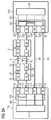
- Fig. 3 shows in the schematic diagram a third embodiment of a fault tolerant master-slave communication system according to the invention, wherein Fig. 3A normal operation and Fig. 3B Perform a reconfiguration operation in case of failure of the main master unit.
- the communication system has a main master unit 110, whose receiving unit RX 12 is connected via the second connection 112 to a first master communication path 43 and its transmission unit TX 11 via the connection 111 to a second master communication path 44.
- a second transmission unit TX 16 and a second reception unit RX 15 are provided.
- the second transmission unit TX 16 is connected to the first communication path 41 via a third connection 114.
- the second receiving unit RX 15 is connected to the second communication path 42 via a fourth connection 113.
- a master coupling device 130 is connected, the control lines 140 between the central control unit 13 and the transmitting or receiving units according to the respective operating mode, ie Normal operation and reconfiguration operation switches through.
- a replacement master unit 210 is constructed symmetrically to the main master unit and has, as in the Fig. 3
- two transmission units TX 22, TX 26 are connected to the second communication path 42 and the first master communication path 43 via the first connection 222 and the third connection 223.
- a further second receiving unit RX 27 is provided, which is connected via a fourth terminal 224 to the second master communication path 44 is.
- a master coupling device 231 is connected in the replacement master unit 210, the control lines 251 between the central control unit 24 and the transmitting or Reception units according to the respective operating state ie normal operation and reconfiguration operation switches through.
- the slave units are analogous to those in Fig. 1 and 2 constructed slave units, with a port 0 and a port 1, each having a combination of a transmitting unit and a receiving unit.
- a coupling device which connects the first receiving unit RX 31 and the second transmitting unit TX 34 in the port 0.
- Fig. 3A shows the trouble-free normal operation in the master-slave communication system.
- the direction of the data transmission is indicated as an arrow, with the lines and transmission paths used for the data transmission being highlighted.
- a data packet is forwarded from the central control unit 13 of the main master unit 110 via the master coupling device 130 to the first transmitting unit TX 11, which outputs the data packet to the second master communication path 44.
- the telegram is then received by the second receiving unit RX 27 of the replacement master unit 210 connected to this second master communication path 44 and coupled by short-circuit connection of the control line 251 by the master coupling device 321 to the first transmitting unit TX 22, which transmits the data packet via the second Communication path 42 outputs to the connected slave unit N.
- the data packet is then looped through all salve units connected serially to the second communication path 42 and transmit from the slave unit 3 adjacent to the master master unit 110 to the second receiving unit RX 15 of the master master unit 110.
- the master coupling device 130 switches on the second receiving unit RX 15 to the second transmitting unit TX 16, which then applies the received data packet to the first communication path 41.
- the data packet then in turn passes through all the slave units arranged serially on this first communication path 41, wherein the data packet is processed as it passes through the processing device 35 respectively arranged in the data path.
- the data packet is then fed back to the first receiving unit RX 21 of the replacement master unit 210, which is short-circuited via the master coupling device 231 to the second transmitting unit TX 26.
- the second transmission unit TX 26 then returns the data packet via the first master communication path 43 to the first reception unit RX 12 of the main master unit 110, which forwards the data packet to the control unit 13 for evaluation.
- the master coupling device 231 in the spare master unit 210 detects a time-out in the data transmission from the master master unit 110 on the second master communication path 44, raises the short circuits between the first receiving unit RX 21 and the second transmitting unit TX 26 second receiving unit RX 27 and the first transmitting unit TX 22.
- the control unit 24 of the spare master unit 210 detects the opening of the short circuits and automatically starts the transmission operation by outputting a data packet generated by the central control unit 24 to the second communication path 42 via the first transmission unit TX 22 and the second terminal 222.
- the data packet then passes through the slave units connected to the second communication path 42 and the main master unit in analogy to normal operation, the main master unit short circuits the first and second communication paths via the coupling device 130.
- the data packet subsequently processed on the return path via the first communication path 41 by the slave units is then received by the first receiving unit RX 21 of the replacement master unit 210 and forwarded to the control unit 24 for evaluation.
- the coupling device and the second port with the second transmission unit TX 16 and the second reception unit RX 15 can be dispensed with in the main master unit.
- the feedback of the data packet from the second communication path 42 to the first communication path 41 in the last slave unit 3 before the master unit via an additional coupling device 36, as shown in the Fig. 1 and 2 Slave unit shown in port 0 is to be fed back.
- the main master unit 110 transmits via the second transmitting unit TX 16 and receives via the second receiving unit RX 15, which are correspondingly switched through by the coupling device 130 to the control unit 13.
- the first transmitting unit TX transmits 22 and receives via the first receiving unit RX 21, which are connected by the coupling device 231 for this purpose with the central control unit 24.
- the central control unit 24 With the in Fig. 3 Thus, a maximum error tolerance in the master-slave communication system is possible.
Description
Die Erfindung betrifft ein Kommunikationssystem mit einer Master-Slave-Struktur und eine Mastereinheit für ein solches Kommunikationssystem.The invention relates to a communication system with a master-slave structure and a master unit for such a communication system.
In der Fertigungs- und Automatisierungstechnik werden zunehmend serielle Bussysteme eingesetzt, bei denen die dezentral angeordneten Geräte einer Maschinenperipherie wie E/A-Module, Messumformer, Antriebe, Ventile und Bedienerterminals über ein leistungsfähiges Echtzeit-Kommunikationssystem mit Automatisierungs-, Engineerings- oder Visualisierungssystemen kommunizieren. Alle Teilnehmer sind dabei über einen seriellen Bus, vorzugsweise über einen Feldbus miteinander vernetzt, wobei der Datenaustausch über den Bus in der Regel auf der Grundlage des Master-Slave-Prinzips ausgeführt wird.In manufacturing and automation technology, serial bus systems are increasingly being used in which the decentralized devices of a machine periphery such as I / O modules, transducers, drives, valves and operator terminals communicate via an efficient real-time communication system with automation, engineering or visualization systems. All subscribers are networked with each other via a serial bus, preferably via a field bus, wherein the data exchange over the bus is usually carried out on the basis of the master-slave principle.
Die aktiven Busteilnehmer am Bussystem, in der Regel Steuergeräte, sind im Besitz einer Buszugriffsberechtigung und bestimmen den Datentransfer auf dem Bus. Die aktiven Busteilnehmer werden im Folgenden als die Mastereinheiten im seriellen Bussystem bezeichnet. Passive Busteilnehmer sind dagegen in der Regel Maschinenperipheriegeräte. Sie erhalten keine Buszugriffsberechtigung, d.h. sie dürfen nur empfangene Informationssignale quittieren oder auf Anfrage einer Mastereinheit Informationssignale an diese übermitteln. Die passiven Busteilnehmer werden im Folgenden als Slaveeinheiten im seriellen Bussystem bezeichnet.The active bus subscribers on the bus system, usually controllers, are in possession of a bus access authorization and determine the data transfer on the bus. The active bus users are referred to below as the master units in the serial bus system. Passive bus users, on the other hand, are usually machine peripherals. You do not receive bus access authorization, i. they may acknowledge only received information signals or transmit information signals to a master unit on request. The passive bus users are referred to below as slave units in the serial bus system.
Feldbussysteme mit einer Master-Slave-Struktur werden im Allgemeinen, um eine aufwändige Verkabelung zu vermeiden, in Ringtopologie ausgeführt, wobei alle Busteilnehmer an einen ringförmigen Übertragungsweg angeschlossen sind. Ein von der Mastereinheit erzeugtes Informationssignal wird von der Mastereinheit in den ringförmigen Übertragungsweg eingespeist und durchläuft nacheinander die seriell an den ringförmigen Übertragungsweg angeschlossenen Slaveeinheiten, um dann wieder von der Mastereinheit empfangen und ausgewertet zu werden.Field bus systems with a master-slave structure are generally implemented in ring topology, in order to avoid complicated wiring, with all bus users being connected to an annular transmission path. An information signal generated by the master unit is fed from the master unit into the annular transmission path and successively traverses the slave units serially connected to the annular transmission path, and then again to be received and evaluated by the master unit.
Die Informationssignale werden von der Mastereinheit in der Regel in Datenpaketen organisiert, die sich aus Steuerdaten und Nutzdaten zusammensetzen, wobei vorzugsweise der Ethernet-Standard verwendet wird, der Datenpakete mit einer Länge von bis zu 1500 Byte bei einer gleichzeitig hohen Übertragungsgeschwindigkeit von 100 Mbit/sec ermöglicht. Jede der an den ringförmigen Übertragungsweg angeschlossenen Slaveeinheiten verarbeitet dann die für ihn bestimmten Nutzdaten der von der Mastereinheit auf dem ringförmigen Übertragungsweg eingespeisten Ethernet-Telegramme.The information signals are organized by the master unit usually in data packets, which are composed of control data and payload, preferably using the Ethernet standard, the data packets with a length of up to 1500 bytes at a high transmission speed of 100 Mbit / sec allows. Each of the slave units connected to the annular transmission path then processes the user data intended for it for the Ethernet telegrams fed in by the master unit on the ring-shaped transmission path.
Die Master-Slave-Kommunikationssysteme mit Ringstruktur sind in der Regel so aufgebaut, dass die Mastereinheit eine Sendeeinheit als Dateneinkoppelstelle und eine Empfangseinheit als Datenauskoppelstelle aufweist. Die einzelnen Slaveeinheiten sind dann am Übertragungsweg zu einem Ring zusammengeschlossen, wobei jeder Teilnehmer mit zwei Nachbarn, der erste und der letzte Teilnehmer im Ring mit der Mastereinheit verbunden ist. Die Übertragung der Datenpakete erfolgt dabei in eine Richtung ausgehend von der Mastereinheit über deren Sendeeinheit zur ersten angeschlossenen Slaveeinheit und von dort zur nächsten, bis die in Datenübertragungsrichtung letzte Slaveeinheit im Ring erreicht ist, und dann zurück zur Empfangseinheit der Mastereinheit.The master-slave communication systems with ring structure are usually constructed so that the master unit has a transmitting unit as a data input point and a receiving unit as a data extraction point. The individual slave units are then combined on the transmission path to a ring, each participant is connected to two neighbors, the first and the last participant in the ring with the master unit. The transmission of the data packets takes place in one direction, starting from the master unit via its transmitting unit to the first connected slave unit and from there to the next, until the data transmission direction last slave unit is reached in the ring, and then back to the receiving unit of the master unit.
Jede Slaveeinheit weist zum Empfang der umlaufenden Datenpakete vom vorherigen Teilnehmer einen ersten Anschluss und zur Weitergabe an den nachfolgenden Teilnehmer einen zweiten Anschluss auf, wobei zwischen den beiden Anschlüssen eine Verarbeitungseinrichtung angeordnet ist, um die durch die Slaveeinheit durchlaufenden Datenpakete zu verarbeiten.Each slave unit has a first connection for receiving the circulating data packets from the previous user and a second connection for forwarding to the subsequent user, a processing device being arranged between the two connections in order to process the data packets passing through the slave unit.
Eine Anforderung an Master-Slave-Kommunikationssysteme, insbesondere beim Einsatz in der Fertigungs- und Prozessautomatisierung, ist eine hohe Fehlertoleranz, also die Fähigkeit des Kommunikationssystems, trotz des Auftretens von Fehlern die geforderte Funktion, d.h. zum Beispiel die Herstellung eines Werkstücks zu gewährleisten. Fehler im Kommunikationssystem, die ohne Beeinträchtigung überstanden werden müssen, sind dabei neben Fehlern in den Datenpaketen auch der Ausfall eines Teilnehmers insbesondere der Mastereinheit im Übertragungsweg bzw. eine Unterbrechung des Übertragungsweges, beispielsweise durch physikalisches Durchtrennen des Übertragungsmediums.A requirement for master-slave communication systems, especially when used in production and process automation, is a high fault tolerance, so the ability of the communication system, despite the occurrence of errors, the required function, ie, for example, to ensure the production of a workpiece. Errors in the communication system, which must be overcome without impairment, are in addition to errors in the data packets and the failure of a subscriber in particular the master unit in the transmission path or an interruption of the transmission path, for example by physical severing of the transmission medium.
Ein Master-Slave-Kommunikationssystem mit zwei Master-Knoten, um den Ausfall eines Master-Knotens zu kompensieren, und einer Doppelleitungsstruktur, um bei einer Unterbrechung zwischen den Leitungen umschalten zu können, ist aus der
Aufgabe der vorliegenden Erfindung ist es, ein Kommunikationssystem mit einer Master-Slave-Struktur und eine Mastereinheit für ein solches Kommunikationssystem bereitzustellen, die bei einem minimalen Hardware und Schaltaufwand die Möglichkeit einer Rekonfiguration der Master-Slave-Struktur in Echtzeit bei einer Unterbrechung des Übertragungsweges, insbesondere bei Ausfall der Mastereinheit ermöglichen.The object of the present invention is to provide a communication system with a master-slave structure and a master unit for such a communication system, which with minimal hardware and switching overhead, the possibility of reconfiguration of the master-slave structure in real time in an interruption of the transmission path, especially in case of failure of the master unit allow.
Diese Aufgabe wird eine Mastereinheit nach Anspruch 1 und ein Kommunikationssystem nach Anspruch 4. Bevorzugte Weiterbildungen sind in den abhängigen Ansprüchen angegeben.This object is achieved by a master unit according to
Erfindungsgemäß sind in einem Kommunikationssystem eine erste und eine zweite Mastereinheit und wenigstens eine Slaveeinheit über eine Doppelleitungsstruktur miteinander verbunden sind. Die erste und die zweite Mastereinheit weisen jeweils eine Sendeeinheit zum Senden von Datensignalen, die über erste Anschlüsse mit der Doppelleitungsstruktur verbunden sind, jeweils eine Empfangseinheit zum Empfangen von Datensignalen, die über zweite Anschlüsse mit der Doppelleitungsstruktur verbunden sind, und jeweils eine Steuereinheit zum Übertragen von Datensignalen, die mit den Sendeeinheiten und den Empfangseinheiten verbunden sind, auf. Die zweite Master-Einheit umfasst weiter eine Master-Kopplungseinrichtung, die zwischen die Steuereinheit, die Empfangseinheit und die Sendeeinheit geschaltet ist, um in einem ersten Betriebsmodus bei Empfang von Datensignalen der ersten Mastereinheit auf der Doppelleitungsstruktur die Steuereinheit von der Empfangseinheit und der Sendeeinheit zu trennen und um in einem zweiten Betriebsmodus bei Unterbrechung des Empfang von Datensignalen der ersten Mastereinheit auf der Doppelleitungsstruktur die Steuereinheit mit der Empfangseinheit und der Sendeeinheit zu verbinden, um eine Datenübertragung auf der Doppelleitungsstruktur durchzuführen.According to the invention, in a communication system, a first and a second master unit and at least one slave unit connected by a double line structure. Each of the first and second master units has a transmitting unit for transmitting data signals connected to the double line structure via first terminals, a receiving unit for receiving data signals connected to the double line structure via second terminals, and a control unit for transmitting Data signals that are connected to the transmitting units and the receiving units on. The second master unit further comprises a master coupling device which is connected between the control unit, the receiving unit and the transmitting unit in order to separate the control unit from the receiving unit and the transmitting unit in a first operating mode upon receipt of data signals of the first master unit on the double line structure and in a second operation mode, upon interruption of the reception of data signals of the first master unit on the double line structure, the control unit is connected to the reception unit and the transmission unit to perform data transmission on the double line structure.
Erfindungsgemäß ist die zweite Ersatz-Mastereinheit in die Datenübertragungskette von erster regulärer Mastereinheit zu den Slaveeinheiten geschaltet, um bei Auftreten eines Streckenfehlers, insbesondere bei Ausfall der ersten regulären Mastereinheit, die Datenübertragung fortzuführen.According to the invention, the second substitute master unit is connected in the data transmission chain from the first regular master unit to the slave units in order to continue the data transmission when a route error occurs, in particular in the event of failure of the first regular master unit.
Eine erfindungsgemäße Mastereinheit zum Einsatz als Ersatz-mastereinheit weist eine Sendeeinheit zum Senden von Datensignalen, die über einen ersten Anschluss mit einem ersten Kommunikationspfad verbunden werden kann, eine Empfangseinheit zum Empfangen von Datensignalen, die über einen zweiten Anschluss mit einem Kommunikationspfad verbunden werden kann, und eine Steuereinheit zum Übertragen von Datensignalen und eine Master-Kopplungseinrichtung auf. Die Master-Kopplungseinrichtung ist dabei zwischen die Steuereinheit, die Sendeeinheit und die Empfangseinheit geschaltet, um in einem ersten Betriebsmodus, d.h. im Normalbetrieb, die Steuereinheit von der Empfangseinheit und der Sendeeinheit zu trennen und um in einem zweiten Betriebsmodus, d.h. im Streckenfehlerbetrieb, die Steuereinheit mit der Empfangseinheit und der Sendeeinheit zu verbinden, um eine Datenübertragung auf dem ersten und dem zweiten Kommunikationspfad durchzuführen.A master unit according to the invention for use as a replacement master unit has a transmitting unit for transmitting data signals, which can be connected via a first connection to a first communication path, a receiving unit for receiving data signals, which can be connected to a communication path via a second connection, and a control unit for transmitting data signals and a master coupling device. The master coupling device is connected between the control unit, the transmitting unit and the receiving unit in order to a first operating mode, ie in normal operation, to separate the control unit from the receiving unit and the transmitting unit and to connect the control unit to the receiving unit and the transmitting unit in a second operating mode, ie in route error operation, to transfer data on the first and the second communication path perform.
Mit der erfindungsgemäßen Auslegung eines Master-Slave-Kommunikationssystems bzw. einer Ersatz-Mastereinheit ist es möglich, bei einem Streckenfehler, insbesondere bei Ausfall der regulären Mastereinheit, auf einfache Weise die Datenübertragung durch die Ersatz-Mastereinheit fortzuführen. Erfindungsgemäß wird der Datenübertragungsweg automatisch so rekonfiguriert, dass die Ersatz-Mastereinheit die Datenübertragung in dem von der regulären Mastereinheit abgetrennten Teil des Master-Slave-Kommunikationssystems übernimmt.With the inventive design of a master-slave communication system or a replacement master unit, it is possible in a route error, in particular in case of failure of the regular master unit, to continue the data transmission through the replacement master unit in a simple manner. According to the invention, the data transmission path is automatically reconfigured in such a way that the replacement master unit takes over the data transmission in the part of the master-slave communication system which is separated from the regular master unit.
Gemäß einer erfindungsgemäßen Ausführungsform sind in dem Kommunikationssystem die erste und die zweite Mastereinheit vorgesehen, zwischen denen die wenigstens eine Slaveeinheit angeordnet ist. Die Slaveeinheit weist eine Slave-Kopplungseinrichtung und einen ersten, zweiten, dritten und vierten Anschluss auf. Der erste Anschluss der Slaveeinheit ist mit der Sendeeinheit der ersten Mastereinheit und der zweite Anschluss der Slaveeinheit mit der Empfangseinheit der zweite Mastereinheit über einen ersten Kommunikationspfad der Doppelleitungsstruktur verbunden. Der dritte Anschluss der Slaveeinheit ist mit der Sendeeinheit der zweiten Mastereinheit und der vierte Anschluss der Slaveeinheit mit der Empfangseinheit der ersten Mastereinheit über einen zweiten Kommunikationspfad der Doppelleitungsstruktur verbunden. Im ersten Betriebsmodus, d.h. im Normalbetrieb, schließt die Master-Kopplungseinrichtung der zweite Mastereinheit den ersten mit der Sendeeinheit verbundenen Anschluss und den zweiten mit der Empfangseinheit verbundenen Anschluss der zweite Mastereinheit kurz und die Datenübertragung erfolgt ausschließlich durch die erste Master-Einheit. Im zweiten Betriebsmodus, d.h. bei Auftreten eines Streckenfehlers, schließt die Slave-Kopplungseinrichtung der Slaveeinheit den ersten Anschluss der Slaveeinheit mit dem vierten Anschluss der Slaveeinheit kurz. Gleichzeitig öffnet die Master-Kopplungseinrichtung der zweite Mastereinheit zur Datenübertragung auf dem ersten und zweiten Kommunikationspfad den Kurzschluss von erstem und zweitem Anschluss der zweite Mastereinheit und verbindet die Steuereinheit mit der Sendeeinheit und der Empfangseinheit zum Datenübertragungsbetrieb.According to one embodiment of the invention, the first and second master units are provided in the communication system, between which the at least one slave unit is arranged. The slave unit has a slave coupling device and a first, second, third and fourth connection. The first terminal of the slave unit is connected to the transmitting unit of the first master unit and the second terminal of the slave unit to the receiving unit of the second master unit via a first communication path of the double line structure. The third connection of the slave unit is connected to the transmission unit of the second master unit and the fourth connection of the slave unit to the reception unit of the first master unit via a second communication path of the double line structure. In the first operating mode, ie in normal operation, the master coupling device of the second master unit short-circuits the first connection connected to the transmission unit and the second connection of the second master unit connected to the reception unit, and the data transmission takes place exclusively through the first master unit. In the second operating mode, ie when a path error occurs, the slave coupling device of the slave unit short-circuits the first connection of the slave unit to the fourth connection of the slave unit. At the same time, the master coupling device of the second master unit for data transmission on the first and second communication paths opens the short circuit of the first and second terminals of the second master unit and connects the control unit with the transmitting unit and the receiving unit for data transmission operation.
Gemäß einer erfindungsgemäßen Ausführungsform der Mastereinheit schließt die Master-Kopplungseinrichtung im ersten Betriebsmodus den ersten mit der Sendeeinheit verbundenen Anschluss und den zweiten mit der Empfangseinheit verbundenen Anschluss kurz und hebt im zweiten Betriebsmodus den Kurzschluss von erstem und zweitem Anschluss auf.According to an embodiment of the master unit according to the invention, in the first operating mode, the master coupling device short-circuits the first terminal connected to the transmitting unit and the second terminal connected to the receiving unit and, in the second operating mode, removes the short circuit from the first and second terminals.
Gemäß einer weiteren erfindungsgemäßen Ausführungsform des Kommunikationssystem weist die Slaveeinheit wenigstens einen ersten, zweiten und dritten Anschluss auf, wobei der erste Anschluss der Slaveeinheit mit der Sendeeinheit der ersten Mastereinheit und der zweite Anschluss der Slaveeinheit mit der Empfangseinheit der zweite Mastereinheit über einen ersten Kommunikationspfad der Doppelleitungsstruktur verbunden sind. Der dritte Anschluss der Slaveeinheit ist mit der Sendeeinheit der zweiten Mastereinheit über einen zweiten Kommunikationspfad der Doppelleitungsstruktur und ein dritter Anschluss der zweiten Mastereinheit ist mit der Empfangseinheit der ersten Mastereinheit über einen dritten Kommunikationspfad der Doppelleitungsstruktur verbunden. Im ersten Betriebsmodus, d.h. bei Normalbetrieb, schließt die Master-Kopplungseinrichtung der zweite Mastereinheit den zweiten mit der Empfangseinheit verbundenen Anschluss und den dritten Anschluss der zweite Mastereinheit kurz und die Datenübertragung erfolgt ausgehend von der ersten Mastereinheit über den ersten und dritten Kommunikationspfad. Im zweiten Betriebsmodus, d.h. bei Auftreten eines Streckenfehler, schließt die Slave-Kopplungseinrichtung der Slaveeinheit den ersten Anschluss der Slaveeinheit mit dem vierten Anschluss der Slaveeinheit kurz und die Master-Kopplungseinrichtung der zweite Mastereinheit hebt zur Datenübertragung auf dem ersten und zweiten Kommunikationspfad den Kurzschluss von zweitem und drittem Anschluss der zweite Mastereinheit auf und verbindet die Steuereinheit mit der Sendeeinheit und der Empfangseinheit zum Datenübertragungsbetrieb.According to a further embodiment of the communication system according to the invention, the slave unit has at least one first, second and third connection, wherein the first connection of the slave unit with the transmission unit of the first master unit and the second connection of the slave unit with the reception unit of the second master unit via a first communication path of the double line structure are connected. The third terminal of the slave unit is connected to the transmitting unit of the second master unit via a second communication path of the double line structure, and a third terminal of the second master unit is connected to the receiving unit of the first master unit via a third communication path of the double line structure. In the first operating mode, ie during normal operation, the master coupling device of the second master unit short-circuits the second terminal connected to the receiving unit and the third terminal of the second master unit, and the data is transferred from the first master unit via the first and third communication paths. In the second operating mode, ie when a route error occurs, the slave coupling device of the slave unit short-circuits the first terminal of the slave unit to the fourth terminal of the slave unit and the master-coupling unit of the second master unit removes the short circuit of the second and third terminals for data transmission on the first and second communication paths second master unit and connects the control unit with the transmitting unit and the receiving unit for data transmission operation.
Gemäß einer weiteren erfindungsgemäßen Ausführungsform der Mastereinheit ist ein mit einem dritten Kommunikationspfad verbindbarer dritter Anschluss vorgesehen. Die Master-Kopplungseinrichtung schließt dann im ersten Betriebsmodus den zweiten mit der Empfangseinheit verbundenen Anschluss und den dritten Anschluss kurz und hebt im zweiten Betriebsmodus den Kurzschluss von zweitem und drittem Anschluss auf.In accordance with a further embodiment of the master unit according to the invention, a third connection which can be connected to a third communication path is provided. In the first operating mode, the master coupling device then briefly closes the second terminal connected to the receiving unit and the third terminal and, in the second operating mode, releases the short circuit from the second and third terminal.
Gemäß einer weiteren erfindungsgemäßen Ausführungsform weist die Slaveeinheit einen ersten und einen zweiten Anschluss auf, wobei der erste Anschluss der Slaveeinheit mit der Empfangseinheit der zweiten Mastereinheit über einen ersten Kommunikationspfad der Doppelleitungsstruktur, der zweite Anschluss der Slaveeinheit mit der Sendeeinheit der zweite Mastereinheit über einen zweiten Kommunikationspfad der Doppelleitungsstruktur, ein dritter Anschluss der zweiten Mastereinheit mit der Empfangseinheit der ersten Mastereinheit über einen dritten Kommunikationspfad der Doppelleitungsstruktur und ein vierter Anschluss der zweiten Mastereinheit mit der Sendeeinheit der ersten Mastereinheit über einen vierten Kommunikationspfad der Doppelleitungsstruktur verbunden sind. Im ersten Betriebsmodus, d.h. im Normalbetrieb, schließt die Master-Kopplungseinrichtung der zweiten Mastereinheit jeweils den ersten mit der Sendeeinheit verbundenen Anschluss und den vierten Anschluss der zweiten Mastereinheit und den zweiten mit der Empfangseinheit verbundenen Anschluss und den dritten Anschluss der zweiten Mastereinheit kurz und die Datenübertragung erfolgt ausschließlich durch die erste Master-Einheit. Im zweiten Betriebsmodus, d.h. bei Auftreten eines Streckenfehlers, hebt die Master-Kopplungseinrichtung der zweiten Mastereinheit zur Datenübertragung auf dem ersten und zweiten Kommunikationspfad den Kurzschluss von erstem und viertem Anschluss der zweiten Mastereinheit und den Kurzschluss von zweitem und drittem Anschluss der zweiten Mastereinheit auf und verbindet die Steuereinheit mit der Sendeeinheit und der Empfangseinheit zum Datenübertragungsbetrieb.According to a further embodiment of the invention, the slave unit has a first and a second connection, the first connection of the slave unit to the reception unit of the second master unit via a first communication path of the double-line structure, the second connection of the slave unit to the transmission unit of the second master unit via a second communication path the double line structure, a third terminal of the second master unit are connected to the receiving unit of the first master unit via a third communication path of the double line structure and a fourth terminal of the second master unit to the transmitting unit of the first master unit via a fourth communication path of the double line structure. In the first operating mode, ie in normal operation, the master coupling device of the second master unit short-circuits each of the first terminal connected to the transmitting unit and the fourth terminal of the second master unit and the second terminal connected to the receiving unit and the third terminal of the second master unit and the data transmission takes place exclusively through the first master unit. In the second operating mode, ie when a path error occurs, the master coupling device of the second master unit for data transmission on the first and second communication path, the short circuit of the first and fourth terminals of the second master unit and the short circuit of the second and third terminals of the second master unit and connects the control unit with the transmitting unit and the receiving unit for data transmission operation.
Gemäß einer weiteren erfindungsgemäßen Ausführungsform der Mastereinheit ist ein mit einem dritten Kommunikationspfad verbindbarer dritter Anschluss und ein mit einem vierten Kommunikationspfad verbindbarer vierter Anschluss vorgesehen. Die Master-Kopplungseinrichtung schließt im ersten Betriebsmodus den zweiten und den dritten Anschluss sowie den ersten den vierten Anschluss kurz und hebt im zweiten Betriebsmodus den Kurzschluss von zweitem und drittem Anschluss sowie von erstem und viertem Anschluss auf.According to a further embodiment of the master unit according to the invention, a third connection which can be connected to a third communication path and a fourth connection which can be connected to a fourth communication path are provided. In the first operating mode, the master coupling device short-circuits the second and the third connection and the first the fourth connection and, in the second operating mode, releases the short circuit from the second and third connection as well as from the first and fourth connection.
Bei der ersten erfindungsgemäßen Variante ist der Übertragungsweg als physikalische Linie mit einer Doppelleitungsstruktur ausgebildet, wobei die Slaveeinheit jeweils zwei Ports mit jeweils zwei Anschlüssen, an die die Doppelleitungsstruktur angeschlossen sind, umfasst. Die Übertragungskette wird auf der einen Seite durch die reguläre Mastereinheit und auf der anderen Seite durch die Ersatz-Mastereinheit abgeschlossen. Im Normalbetrieb sendet und empfängt die reguläre Mastereinheit über die Doppelleitungsstruktur, wobei die Ersatz-Mastereinheit als Leitungsabschluss dient, über den die Doppelleitung kurzgeschlossen ist, um die von der regulären Mastereinheit auf der ersten Leitung eintreffenden Datenpakete auf der zweiten Leitung zur regulären Mastereinheit rückzukoppeln. Bei Auftreten eines Streckenfehlers, insbesondere bei Ausfall der regulären Mastereinheit, schließt die Slaveeinheit ihren an die reguläre Mastereinheit angekoppelten Port kurz. Gleichzeitig öffnet die Master-Kopplungseinrichtung der Ersatz-Mastereinheit den internen Kurzschluss und verbindet die eine erste Steuerleitung der Steuereinheit mit der Sendeeinheit und eine andere zweite Steuerleitung der Steuereinheit mit der Empfangseinheit, um die Datenübertragung aufzunehmen.In the first variant according to the invention, the transmission path is designed as a physical line with a double-line structure, the slave unit each having two ports each having two terminals to which the double-line structure is connected. The transmission chain is terminated on one side by the regular master unit and on the other side by the replacement master unit. In normal operation, the regular master unit transmits and receives over the dual-line structure, with the spare master unit serving as a line terminator over which the dual line is shorted to feed back the data packets arriving from the regular master unit on the first line to the regular master unit. If a route error occurs, in particular if the regular master unit fails, the slave unit briefly closes its port coupled to the regular master unit. At the same time, the master coupling device opens the replacement master unit the internal short circuit and connects the one first control line of the control unit to the transmitting unit and another second control line of the control unit to the receiving unit to receive the data transmission.
Bei der zweiten erfindungsgemäßen Variante ist das Master-Slave-Kommunikationssystem als Ringstruktur ausgebildet, wobei die Ersatz-Mastereinheit im Normalbetrieb in Datenübertragungsrichtung vor der Empfangseinheit der regulären Mastereinheit angeordnet ist, um die übertragenen Datenpakete auf die reguläre Mastereinheit rückzukoppeln. Im Fehlerbetrieb bei Auftreten eines Streckenfehlers, insbesondere bei Ausfall der reguläre Mastereinheit, öffnet die Master-Kopplungseinrichtung diesen Kurzschluss und verbindet die Sendeeinheit und die Empfangseinheit mit der Steuereinheit, um die Datenübertragung aufzunehmen.In the second variant of the invention, the master-slave communication system is formed as a ring structure, wherein the replacement master unit is arranged in the data transfer direction in the normal direction in front of the receiving unit of the regular master unit to feed back the transmitted data packets to the regular master unit. In error mode when a path error occurs, in particular in the event of failure of the regular master unit, the master coupling device opens this short circuit and connects the transmitting unit and the receiving unit to the control unit to record the data transmission.
Bei der dritten erfindungsgemäßen Variante ist das Master-Slave-Kommunikationssystem als Ringstruktur ausgebildet, wobei die Ersatz-Mastereinheit im Normalbetrieb in Datenübertragungsrichtung zwischen den Slaveeinheiten und der regulären Mastereinheit angeordnet ist, um die Datenpakete der regulären Mastereinheit durchzureichen. Im Fehlerbetrieb bei Auftreten eines Streckenfehlers, insbesondere bei Ausfall der regulären Mastereinheit, öffnet die Master-Kopplungseinrichtung diese Kurzschlüsse und verbindet die Steuereinheit mit der Sendeeinheit und der Empfangseinheit, um die Datenübertragung aufzunehmen.In the third variant of the invention, the master-slave communication system is designed as a ring structure, wherein the replacement master unit is arranged in the normal data transfer direction between the slave units and the regular master unit to pass through the data packets of the regular master unit. In error mode when a path error occurs, in particular in the event of failure of the regular master unit, the master coupling device opens these short circuits and connects the control unit with the transmitting unit and the receiving unit to record the data transmission.
Mit diesen drei erfindungsgemäßen Auslegungen eines Master-Slave-Kommunikationssystems mit einer Ersatz-Mastereinheit ist es möglich, bei einem Streckenfehler, insbesondere bei Ausfall der regulären Mastereinheit, auf einfache Weise die Datenübertragung durch die Ersatz-Mastereinheit fortzuführen. Erfindungsgemäß wird der Datenübertragungsweg automatisch so rekonfiguriert, dass die Ersatz-Mastereinheit die Datenübertragung in dem von der regulären Mastereinheit abgetrennten Teil des Master-Slave-Kommunikationssystems übernimmt.With these three inventive interpretations of a master-slave communication system with a replacement master unit, it is possible to easily continue the data transmission through the replacement master unit in the event of a route error, in particular in the event of failure of the regular master unit. According to the invention, the data transmission path is automatically reconfigured such that the replacement master unit transmits the data in the part of the master-slave communication system separated from the regular master unit.
Mit diesen drei erfindungsgemäßen Auslegungen eines Master-Slave-Kommunikationssystems mit einer Ersatz-Mastereinheit ist es möglich, bei einem Streckenfehler, insbesondere bei Ausfall der regulären Mastereinheit, auf einfache Weise die Datenübertragung durch die Ersatz-Mastereinheit fortzuführen. Erfindungsgemäß wird der Datenübertragungsweg automatisch so rekonfiguriert, dass die Ersatz-Mastereinheit die Datenübertragung in dem von der regulären Mastereinheit abgetrennten Teil des Master-Slave-Kommunikationssystems übernimmt.With these three inventive interpretations of a master-slave communication system with a replacement master unit, it is possible to easily continue the data transmission through the replacement master unit in the event of a route error, in particular in the event of failure of the regular master unit. According to the invention, the data transmission path is automatically reconfigured in such a way that the replacement master unit takes over the data transmission in the part of the master-slave communication system which is separated from the regular master unit.
Die Erfindung wird anhand der beigefügten Zeichnungen näher erläutert. Es zeigen:
-
Fig. 1 eine schematische Darstellung eines erfindungsgemäßen Kommunikationssystems mit einer Master-Slave-Struktur gemäß einer ersten Ausführung mit einer Doppelleitungsstruktur, wobeiFig. 1A den Normalbetrieb undFig. 1B den Rekonfigurationsbetrieb darstellen; -
Fig. 2 eine schematische Darstellung eines erfindungsgemäßen Kommunikationssystems mit Master-Slave-Struktur gemäß einer zweiten Ausführungsform mit einer Ersatzringstruktur, wobei -
Fig. 2A den Normalbetrieb undFig. 2B den Rekonfigurationsbetrieb darstellen; und -
Fig. 3 eine schematische Darstellung eines erfindungsgemäßen Kommunikationssystems mit einer Master-Slave-Struktur gemäß einer dritten Ausführungsform, wobeiFig. 3A den Normalbetrieb undFig. 3B den Rekonfigurationsbetrieb darstellen.
-
Fig. 1 a schematic representation of a communication system according to the invention with a master-slave structure according to a first embodiment with a double-line structure, whereinFig. 1A normal operation andFig. 1B represent the reconfiguration operation; -
Fig. 2 a schematic representation of a communication system according to the invention with master-slave structure according to a second embodiment with a replacement ring structure, wherein -
Fig. 2A normal operation andFig. 2B represent the reconfiguration operation; and -
Fig. 3 a schematic representation of a communication system according to the invention with a master-slave structure according to a third embodiment, whereinFig. 3A normal operation andFig. 3B represent the reconfiguration operation.
In der Automatisierungstechnik werden zunehmend Feldbussysteme eingesetzt, bei denen verteilt angeordnete Geräte der Maschinenperipherie mit Automatisierungs- ,Engineerings- und Visualisierungssystemen über einen Feldbus kommunizieren. Das Feldbussystem weist in der Regel einen seriellen Bus auf, welcher beispielsweise eine elektrische Leitung, ein Lichtleiter oder ein Radiokabel sein kann. An diesem Feldbus sind alle Busteilnehmer angeschlossen, wobei zwischen aktiven und passiven Busteilnehmern unterschieden wird.In automation technology, fieldbus systems are increasingly being used in which distributed devices of the machine peripherals communicate with automation, engineering and visualization systems via a fieldbus. The Fieldbus system usually has a serial bus, which may be, for example, an electrical line, a light guide or a radio cable. All bus subscribers are connected to this fieldbus, whereby a distinction is made between active and passive bus subscribers.
Die aktiven Busteilnehmer am Feldbussystem sind die Mastereinheiten, die den Datenverkehr auf dem Bus regeln. Eine solche Mastereinheit ist z.B. ein Industrie-PC, der als Prozessleitrechner in einer Fertigungsstraße dient. Die Mastereinheit besitzt eine Buszugriffsberechtigung und kann Daten ohne externe Aufforderung auf dem Feldbus ausgeben. Die passiven Busteilnehmer am Bussystem sind die Maschinenperipheriegeräte wie z. B. E/A-Geräte, Ventile, Antriebe und Messumformer. Sie dienen als Slaveeinheiten und besitzen keine Buszugriffsberechtigung, d.h. sie dürfen nur empfangene Datensignale quittieren oder auf Anfrage einer Mastereinheit Datensignale über diese übermitteln.The active bus users on the fieldbus system are the master units that control the traffic on the bus. Such a master unit is e.g. an industrial PC that serves as a process control computer in a production line. The master unit has bus access authority and can output data without external request on the fieldbus. The passive bus users on the bus system are the machine peripherals such. I / O devices, valves, drives and transducers. They serve as slave units and have no bus access authorization, i. they may only acknowledge received data signals or, on request, transmit data signals to a master unit via them.
Als Kommunikationsstandard zur Datenübertragung in Master-Slave-Kommunikationssystemen wird vorzugsweise das Ethernet-Konzept eingesetzt. Bei Ethernet-Kommunikationssystem werden die zu übermittelnden Daten in Form von Datenpaketen, im Weiteren auch als Telegramme bezeichnet, mit einem vorgegebenen Format verkapselt. Die Ethernet-Telegramm können dabei eine Datenlänge von bis zu 1000 Bytes aufweisen, wobei zusätzlich zu den Nutzdaten Steuerdaten, die eine Anfangskennung, eine Ziel- und Quelladresse und einen Datenpaket-Typ und einen Fehlermechanismus aufweisen, enthalten sind.As the communication standard for data transmission in master-slave communication systems, the Ethernet concept is preferably used. In the case of an Ethernet communication system, the data to be transmitted are encapsulated in the form of data packets, also referred to as telegrams, in a predefined format. The Ethernet telegram can have a data length of up to 1000 bytes, wherein in addition to the user data control data, which have an initial identifier, a destination and source address and a data packet type and an error mechanism are included.
Ethernet-Kommunikationssysteme mit einer Master-Slave-Struktur sind vorzugsweise so ausgelegt, dass die einzelnen Mastereinheiten über das Übertragungsmedium zu einer Kette zusammengeschlossen sind, wobei jede Slaveeinheit mit zwei Nachbarn, die erste und die letzte Slaveeinheit in der Kette dabei mit der Mastereinheit verbunden sind, so dass sich eine Ringstruktur ergibt. Die Datenübertragung erfolgt in eine Richtung ausgehend von der Mastereinheit zur ersten benachbarten Slaveeinheit und von dort zur nächsten bis zur letzten Slaveeinheit und dann zurück zur Mastereinheit.Ethernet communication systems with a master-slave structure are preferably designed so that the individual master units are connected to form a chain via the transmission medium, wherein each slave unit with two neighbors, the first and the last slave unit in the chain are connected to the master unit so that a ring structure results. The data transfer takes place in one Direction from the master unit to the first adjacent slave unit and from there to the next to the last slave unit and then back to the master unit.
Um eine Aufrechterhaltung der Datenkommunikation bei Auftreten eines Streckenfehlers auf dem Übertragungsweg, insbesondere bei Ausfall der Mastereinheit zu ermöglichen, ist erfindungsgemäß zusätzlich zur regulären Mastereinheit eine Ersatz-Mastereinheit im Master-Slave-Kommunikationssystem vorgesehen.In order to enable a maintenance of the data communication in the event of a path error on the transmission path, in particular in the event of failure of the master unit, according to the invention a replacement master unit is provided in the master-slave communication system in addition to the regular master unit.
Die Haupt-Mastereinheit 1 weist eine Sendeeinheit TX 11 und eine Empfangseinheit RX 12 auf. Die Sendeeinheit TX 11 ist über einen ersten Anschluss 111 mit dem einen Ende des ersten Kommunikationspfads 41 und die Empfangseinheit RX 12 über einen zweiten Anschluss 112 mit dem einen Ende des zweiten Kommunikationspfads 42 verbunden. Ferner enthält die Mastereinheit 1 eine Steuereinheit 13, die über Steuerleitungen 14 an die Sendeeinheit TX 11 und die Empfangseinheit RX 12 angeschlossen ist.The
Die Ersatz-Mastereinheit 2 weist eine Empfangseinheit RX 21 und eine Sendeeinheit TX 22 auf. Die Empfangseinheit RX 21 ist über einen ersten Anschluss 221 mit dem zweiten Ende des ersten Kommunikationspfads 41 und die Sendeeinheit TX 22 über einen zweiten Anschluss 222 mit dem zweiten Ende des zweiten Kommunikationspfads 42 verbunden. Die Ersatz-Mastereinheit 2 umfasst ferner eine Master-Kopplungseinrichtung 23, die zwischen eine Steuereinheit 24 und deren Steuerleitungen 25 und die Empfangseinheit RX 21 und die Sendeeinheit TX 22 geschaltet ist.The
Jede Slaveeinheit 3 weist zum Empfang der Datenpakete von einem vorherigen Teilnehmer über den ersten Kommunikationspfad 41 einen ersten Anschluss mit einer ersten Empfangseinheit RX 31 und zur Weitergabe an den nächsten Teilnehmer über den ersten Kommunikationspfad 41 einen zweiten Anschluss mit einer ersten Sendeeinheit TX 32 auf. Ferner weist jede Slaveeinheit 3 zum Empfang der Datenpakete über den zweiten Kommunikationspfad 42 von einem vorherigen Teilnehmer einen dritten Anschluss mit einer zweiten Empfangseinheit RX 33 und zur Weitergabe über den zweiten Kommunikationspfad 42 an den folgenden Teilnehmer einen vierten Anschluss mit einer zweiten Sendeeinheit TX 34 auf. Die erste Empfangseinheit RX 31 der Slaveeinheit 3, die an den ersten Kommunikationspfad 41 angeschlossen ist, und die zweite Sendeeinheit TX 34, die an den zweiten Kommunikationspfad 42 angeschlossen ist, sind dabei zu einem gemeinsamen Port 0 zusammengefasst. Die zweite Empfangseinheit RX 33, die an den zweiten Kommunikationspfad 42 angeschlossen ist, und die Sendeeinheit TX 32, die an den ersten Kommunikationspfad 41 angeschlossen sind, sind zu einem gemeinsamen Port 1 zusammengefasst. Zwischen die erste Empfangseinheit RX 31 und die erste Sendeeinheit TX 32 ist eine Verarbeitungseinheit 35 in den ersten Kommunikationspfad 41 geschaltet. Der zweite Kommunikationspfad 42 wird durch die Slaveeinheit 3 von der Empfangseinheit RX 33 zur Sendeeinheit TX 34 durchgeschleift. Die der Haupt-Mastereinheit 1 benachbarte Slaveeinheit weist im an die Haupt-Mastereinheit 1 angeschlossenen Port 0 darüber hinaus eine Kopplungseinrichtung 36 auf, die zwischen die erste Empfangseinheit RX 31 und die zweite Sendeeinheit TX 34 geschaltet ist.Each slave unit 3 has a first connection with a first
Das Datenpaket durchläuft auf diese Weise nacheinander alle auf dem ersten Kommunikationspfad 41 angeschlossenen Slaveeinheiten 3 und wird von der letzten Slaveeinheit 3 auf den ersten Kommunikationspfad 41 über den ersten Anschluss 221 zur Empfangseinheit RX 21 der Ersatz-Mastereinheit 2 übertragen. Im Normalbetrieb schließt die Master-Kopplungseinrichtung 23 der Ersatz-Mastereinheit 2 die Empfangseinheit RX 21 und die Sendeeinheit TX 22 über die Steuerleitungen 25 kurz und die Sendeeinheit TX 22 der Ersatz-Mastereinheit 2 koppelt das Datenpaket über den Anschluss 222 auf den zweiten Kommunikationspfad 42 zurück. Das Datenpaket durchläuft dann, wie auf dem Hinweg, auch auf dem Rückweg in Datenübertragungsrichtung nacheinander die an den zweiten Kommunikationspfad 42 angeschlossenen Slaveeinheiten 3, ausgehend von der Slaveeinheit N bis zur Slaveeinheit 1, wobei das Datenpaket unverarbeitet durch die Slaveeinheiten 3 durchgeschleift wird.The data packet in this way successively passes through all the slave units 3 connected to the
Die in Datenübertragungsrichtung letzte Slaveeinheit am zweiten Kommunikationspfad 42 sendet dann das Datenpaket durch die zweite Sendeeinheit TX 34 im Port 0 über den zweiten Anschluss 112 der Haupt-Mastereinheit 1 an deren Empfangseinheit RX 12, von wo aus das Datenpaket dann zur zentralen Steuereinheit 13 weitergeleitet wird.The last slave unit in the data transmission direction on the
Parallel mit der Aufnahme des Streckenfehlerbetriebs durch die an die Haupt-Mastereinheit 1 angrenzende Slaveeinheit 3 beginnt die Ersatz-Mastereinheit 2 mit der Datenübertragung. Die Aufnahme des Streckenfehlerbetriebs der Ersatz-Mastereinheit 2 wird durch die Master-Kopplungseinrichtung 23 ausgelöst, die aufgrund des Ausfalls der Haupt-Mastereinheit 1 einen Timeout der Datenübertragung auf dem ersten Kommunikationspfad 41 feststellt. Die Master-Kopplungseinrichtung 23 hebt dann den Kurzschluss zwischen der Sendeeinheit TX 22 und der Empfangseinheit RX 21 auf und öffnet die Leitungsverbindung zwischen der zentralen Steuereinheit 24 und der Sendeeinheit TX 22 und der Empfangseinheit RX 21 über die Steuerleitungen 25.In parallel with the recording of the route error operation by the adjacent to the
Die Steuereinheit 24 stellt das Öffnen der Steuerleitungen 25 fest und beginnt dann automatisch mit dem Sendebetrieb, indem die Steuereinheit 24 ein von ihr erzeugtes Datenpaket über die Sendeeinheit TX 22 und den zweiten Anschluss 222 auf den zweiten Kommunikationspfad 42 ausgibt. Das Datenpaket durchläuft dann auf dem zweiten Kommunikationspfad 42 alle daran angeschlossenen Slaveeinheiten 3 nacheinander. Wenn das Datenpaket die an die ausgefallene Haupt-Mastereinheit 1 angrenzende, sich im Streckenfehlerbetrieb befindende Slaveeinheit 3 erreicht hat, wird es über den in der Slaveeinheit 3 von der Slave-Kopplungseinrichtung 36 erzeugten Kurzschluss vom zweiten Kommunikationspfad 42 auf den ersten Kommunikationspfad 41 umgeleitet, wobei auf dem Rückweg die Verarbeitungseinheit 35 in der sich im Streckenfehlerbetrieb befindenden Slaveeinheit 3 durchlaufen wird. Das Datenpaket wird dann von der sich im Streckenfehlerbetrieb befindenden Slaveeinheit 3 zu der auf dem ersten Kommunikationspfad 41 in Datenübertragungsrichtung benachbarten Slaveeinheit 3 weitergeleitet und von dort zur nächsten Slaveeinheit 3 bis das Datenpaket über den Anschluss 221 auf die Empfangseinheit RX 21 der Ersatz-Mastereinheit 2 rückgekoppelt ist, die das empfangene Datenpaket über die Steuerleitung 25 an die Steuereinheit 24 zur Auswertung weiterreicht. Der rekonfigurierte Datenübertragungsweg ist in
Alternativ zu einer einzelnen Slaveeinheit mit einer Slave-Kopplungseinrichtung besteht auch die Möglichkeit, dass alle Slaveeinheiten eine solche Slave-Kopplungseinrichtung aufweisen. Bei Auftreten von Streckenfehlern, d.h. Unterbrechung des Übertragungsweges zwischen den Slaveeinheiten bzw. bei Ausfall einer Slaveeinheit können die benachbarten Slaveeinheiten dann jeweils den an den Streckenfehler angrenzenden Port schließen und den ersten Kommunikationspfad 41 mit dem zweiten Kommunikationspfad 42 verbinden. Die Datenübertragung kann dann zweigeteilt durchgeführt werden, wobei die Slaveeinheiten 3 auf der einen Seite bis zur der an den Streckenfehler angrenzenden Slaveeinheit über die Haupt-Mastereinheit 1 mit Datenpaketen versorgt werden. Auf der bezogen auf den Streckenfehler anderen Datenübertragungsseite dagegen sendet und empfängt die Ersatz-Mastereinheit 2. Es ist so möglich, die Datenübertragung nicht nur beim Ausfall der Haupt-Mastereinheit, sondern auch bei Auftreten eines Streckenfehlers durch Rekonfiguration der Datenübertragungswege unter Einsatz beider Mastereinheiten aufrechtzuerhalten.As an alternative to a single slave unit with a slave coupling device, there is also the possibility that all slave units have such a slave coupling device. When route errors occur, i. Interruption of the transmission path between the slave units or in case of failure of a slave unit, the adjacent slave units can then each close the adjacent to the route error port and connect the
Der zweite Slave-Kommunikationspfad 42 wird im Normalbetrieb nicht benutzt und dient nur als Ersatzkommunikationspfad bei Auftreten eines Streckenfehlers, insbesondere bei Ausfall der Haupt-Mastereinheit 1, wie er in
Bei dem in
Der Sendebetrieb durch die Ersatz-Mastereinheit 200 erfolgt dann analog dem in
Ferner besteht wie auch bei der in
Zwischen die erste Sendeeinheit TX 11, die erste Empfangseinheit RX 12, die zweite Sendeeinheit TX 16 und die zweite Empfangseinheit RX 15 und die Steuereinheit 13 der Haupt-Mastereinheit 110 ist eine Master-Kopplungseinrichtung 130 geschaltet, die Steuerleitungen 140 zwischen der zentralen Steuereinheit 13 und den Sende- bzw. Empfangseinheiten entsprechend dem jeweiligen Betriebsmodus, d.h. Normalbetrieb und Rekonfigurationsbetrieb durchschaltet.Between the first
Eine Ersatz-Mastereinheit 210 ist symmetrisch zur Hauptmastereinheit aufgebaut und weist, wie bei der in
Die Slaveeinheiten sind dabei analog den in
Das Datenpaket wird dann durch alle seriell am zweiten Kommunikationspfad 42 angeschlossenen Salveeinheiten durchschleift und von der der Haupt-Mastereinheit 110 benachbarten Slaveeinheit 3 auf die zweite Empfangseinheit RX 15 der Haupt-Mastereinheit 110 übertragen. In der Haupt-Mastereinheit 110 schaltet im Normalbetrieb die Master-Kopplungseinrichtung 130 die zweite Empfangseinheit RX 15 auf die zweite Sendeeinheit TX 16 auf, die das empfangene Datenpaket dann auf den ersten Kommunikationspfad 41 aufgibt. Das Datenpaket durchläuft dann wiederum alle seriell an diesen ersten Kommunikationspfad 41 angeordnete Slaveeinheiten, wobei das Datenpaket im Durchlauf durch die jeweils im Datenpfad angeordnete Verarbeitungseinrichtung 35 verarbeitet wird. Von der letzten Slaveeinheit N wird das Datenpaket dann auf die erste Empfangseinheit RX 21 der Ersatz-Mastereinheit 210 rückgekoppelt, die über die Master-Kopplungseinrichtung 231 mit der zweiten Sendeeinheit TX 26 kurzgeschaltet ist. Die zweite Sendeeinheit TX 26 sendet das Datenpaket dann über den ersten Master-Kommunikationspfad 43 zur ersten Empfangseinheit RX 12 der Haupt-Mastereinheit 110 zurück, die das Datenpaket zur Auswertung an die Steuereinheit 13 weiterleitet.The data packet is then looped through all salve units connected serially to the
Bei Ausfall der Hauptmastereinheit geht das Master-Slave-Kommunikationssystem in den in
Mit der in
Alternativ besteht auch die Möglichkeit, dass, wenn statt des Ausfalls der Haupt-Mastereinheit die Datenkommunikationsleitung zwischen den Slaveeinheiten unterbrochen ist bzw. eine Slaveeinheit ausgefallen ist und die Slaveeinheiten jeweils Kopplungseinrichtungen zwischen dem ersten und dem zweiten Kommunikationspfad aufweisen, die Datenübertragung zweiteilig ausgeführt wird, wobei die Slaveeinheiten auf der einen Seite des Streckenfehlers von der Haupt-Mastereinheit 110 mit Datenpaketen versorgt werden. Auf der bezogen auf den Streckenfehler anderen Datenübertragungsseite dagegen überträgt die Ersatz-Mastereinheit 210 die Datenpakete. Die Haupt-Mastereinheit 110 sendet dabei über die zweite Sendeeinheit TX 16 und empfängt über die zweite Empfangseinheit RX 15, die entsprechend von der Kopplungseinrichtung 130 auf die Steuereinheit 13 durchgeschaltet werden. In der Ersatz-Mastereinheit 210 sendet die erste Sendeeinheit TX 22 und empfängt über die erste Empfangseinheit RX 21, die von der Kopplungseinrichtung 231 hierfür mit der zentralen Steuereinheit 24 verbunden werden. Mit der in
Claims (5)
- Master unit (200; 210) having
a transmission unit (22) for transmitting data signals that is able to be connected via a first port (222) to a first communication path (41),
a reception unit (21) for receiving data signals that is able to be connected via a second port (221) to a second communication path (42),
a control unit (24) for transmitting data signals, and
a master coupling device (230; 231) that is connected between the control unit (24), the transmission unit (22) and the reception unit (21),
characterized in that
the master coupling device (230; 231) is designed to isolate the control unit (24) from the reception unit (21) and the transmission unit (22) and to short the reception unit (21) to a further transmission unit (26) for transmitting data signals, which is connected via a third port (223) to a first regular master unit (1; 110) via a third communication path (43), in a first mode of operation and to connect the control unit (24) to the reception unit (21) and the transmission unit (22) in a second mode of operation, in order to perform data transmission on the first and second communication paths (41, 42). - Master unit according to Claim 1, characterized by a further reception unit (27) for receiving data signals that is able to be connected via a fourth port (224) to a fourth communication path (44), wherein the master coupling device (231) is designed to short the reception unit (21) to the further transmission unit (26) and the further reception unit (27) to the transmission unit (22) in the first mode of operation.
- Master unit according to Claim 1 or 2, characterized in that the master unit (200; 210) is designed to detect failure of a transmission mode of a further master unit in order then to change over from the first to the second mode of operation.
- Communication system having a first master unit (1; 110), a second master unit (200; 210) according to one of Claims 1 to 3 and at least one slave unit (3), which are connected to one another via a dual line structure (4; 41, 42, 43, 44) having the first communication path (41) and the second communication path (42),
wherein the first master unit (1; 110) has a transmission unit (11) for transmitting data signals that is connected via a first port (111) to the dual line structure (4; 41, 42, 43, 44), a reception unit (12) for receiving data signals that is connected via a second port (112) to the dual line structure (4; 41, 42, 43, 44), and a control unit (13) for transmitting data signals that is connected to the transmission unit and the reception unit. - Communication system according to Claim 4,
wherein the slave unit (3) has a slave coupling device (36) and a first, a second, a third and a fourth port (31, 32, 33, 34),
wherein the first port (31) of the slave unit (3) is connected to the transmission unit (11) of the first master unit (1) and the second port (32) of the slave unit (3) is connected to the reception unit (21) of the second master unit (200) via the first communication path (41) of the dual line structure (4), the third port (33) of the slave unit (3) is connected to the transmission unit (22) of the second master unit (200) and the fourth port (34) of the slave unit (3) is connected to the reception unit (12) of the first master unit (1) via the second communication path (42) of the dual line structure (4), the further transmission unit (26) of the second master unit (200) is connected to the reception unit (12) of the first master unit (1) via the third communication path (43) of the dual line structure (4), wherein in the first mode of operation the master coupling device (230) of the second master unit (200) shorts the reception unit (21) of the second master unit (200) to the further transmission unit (26) of the second master unit (200), and
wherein in the second mode of operation the slave coupling device (36) of the slave unit (3) shorts the first port (31) of the slave unit to the fourth port (34) of the slave unit and the master coupling device (230) of the second master unit (200), for the purpose of data transmission on the first and second communication paths (41, 42), removes the short from the reception unit (21) of the second master unit (200) to the further transmission unit (26) of the second master unit (200) and connects the control unit (24) to the transmission unit (22) and the reception unit (21).
Applications Claiming Priority (2)
| Application Number | Priority Date | Filing Date | Title |
|---|---|---|---|
| DE102006055889A DE102006055889B3 (en) | 2006-11-27 | 2006-11-27 | Communication system with a master-slave structure |
| PCT/EP2007/062831 WO2008065087A2 (en) | 2006-11-27 | 2007-11-26 | Communication system having a master/slave structure |
Publications (2)
| Publication Number | Publication Date |
|---|---|
| EP2098018A2 EP2098018A2 (en) | 2009-09-09 |
| EP2098018B1 true EP2098018B1 (en) | 2016-04-27 |
Family
ID=39326678
Family Applications (1)
| Application Number | Title | Priority Date | Filing Date |
|---|---|---|---|
| EP07847359.2A Active EP2098018B1 (en) | 2006-11-27 | 2007-11-26 | Communication system having a master/slave structure |
Country Status (6)
| Country | Link |
|---|---|
| US (1) | US8531942B2 (en) |
| EP (1) | EP2098018B1 (en) |
| JP (1) | JP5021037B2 (en) |
| CN (1) | CN101542981B (en) |
| DE (1) | DE102006055889B3 (en) |
| WO (1) | WO2008065087A2 (en) |
Families Citing this family (29)
| Publication number | Priority date | Publication date | Assignee | Title |
|---|---|---|---|---|
| US9785700B2 (en) | 2008-02-11 | 2017-10-10 | Nuix Pty Ltd | Systems and methods for load-balancing by secondary processors in parallelized indexing |
| WO2009102765A2 (en) | 2008-02-11 | 2009-08-20 | Nuix North America Inc. | Parallelization of electronic discovery document indexing |
| US9928260B2 (en) | 2008-02-11 | 2018-03-27 | Nuix Pty Ltd | Systems and methods for scalable delocalized information governance |
| JP5080417B2 (en) * | 2008-10-24 | 2012-11-21 | 富士通テレコムネットワークス株式会社 | Packet transmission control system and packet transmission control method |
| EP2224642A1 (en) * | 2009-02-27 | 2010-09-01 | Siemens Aktiengesellschaft | Communication system and communication method for reliable communication with communication participants |
| AU2010268281A1 (en) * | 2009-06-28 | 2012-02-16 | Minetronics Gmbh | Communication network and method for safety-related communication in tunnel and mining structures |
| DE102010029301B4 (en) * | 2010-05-26 | 2014-05-22 | Siemens Aktiengesellschaft | Network and expansion unit and method for operating a network |
| KR101720347B1 (en) * | 2011-01-20 | 2017-03-27 | 엘에스산전 주식회사 | Adaptive multi redundant ring topology system and Method for selecting the detour |
| JP5858037B2 (en) | 2011-03-15 | 2016-02-10 | オムロン株式会社 | Network system, master device and network system control method |
| US10142124B2 (en) * | 2012-05-24 | 2018-11-27 | Infineon Technologies Ag | System and method to transmit data over a bus system |
| CN102684965B (en) * | 2012-05-25 | 2014-10-15 | 长园深瑞继保自动化有限公司 | Ethernet communication method and Ethernet communication device |
| KR101400329B1 (en) * | 2012-08-10 | 2014-05-28 | 삼성중공업 주식회사 | Communication system |
| KR101400325B1 (en) | 2012-08-10 | 2014-05-28 | 삼성중공업 주식회사 | Communication system |
| CA2968432C (en) * | 2013-11-23 | 2019-12-31 | Koenig-Pa Gmbh | Bus participant device and method for the operation of a bus participant device |
| US10826930B2 (en) | 2014-07-22 | 2020-11-03 | Nuix Pty Ltd | Systems and methods for parallelized custom data-processing and search |
| US11200249B2 (en) | 2015-04-16 | 2021-12-14 | Nuix Limited | Systems and methods for data indexing with user-side scripting |
| TWI612788B (en) | 2015-12-21 | 2018-01-21 | 視動自動化科技股份有限公司 | Communication system with train bus architecture |
| EP3185485B1 (en) | 2015-12-21 | 2018-10-10 | ViewMove Technologies Inc. | Communication system with train bus architecture |
| DE102016212198B4 (en) * | 2016-07-05 | 2024-01-25 | Robert Bosch Gmbh | MODULAR SYSTEM AND METHOD FOR COMMUNICATION IN SUCH A MODULAR SYSTEM |
| DE102016212291A1 (en) * | 2016-07-06 | 2018-01-11 | Robert Bosch Gmbh | MODULAR DEVICE FOR A MODULAR SYSTEM AND METHOD FOR COMMUNICATING IN SUCH A MODULAR SYSTEM |
| DE102016113324A1 (en) * | 2016-07-20 | 2018-01-25 | Knorr-Bremse Systeme für Schienenfahrzeuge GmbH | Ethernet network |
| DE102016113322A1 (en) * | 2016-07-20 | 2018-01-25 | Knorr-Bremse Systeme für Schienenfahrzeuge GmbH | Slave control for Ethernet network |
| JP6848730B2 (en) * | 2017-07-07 | 2021-03-24 | オムロン株式会社 | Control system and control method |
| JP6828624B2 (en) * | 2017-07-07 | 2021-02-10 | オムロン株式会社 | Control system and control method |
| KR102048639B1 (en) * | 2018-09-04 | 2019-11-25 | 벨로넥트 인코퍼레이션 | Method for detecting and complementing connection failure of a bus and device for said method |
| JP7203558B2 (en) * | 2018-10-12 | 2023-01-13 | 株式会社Pfu | Communication system, control method and communication module |
| BE1027084B1 (en) * | 2019-02-28 | 2020-09-28 | Constell8 | UNIT FOR CONTROLLING DATA COMMUNICATION |
| CN109993958B (en) * | 2019-05-08 | 2021-06-11 | 深圳市共济科技股份有限公司 | Data acquisition system and method of RS485 bus |
| DE102020127804B4 (en) * | 2020-10-22 | 2022-05-05 | Beckhoff Automation Gmbh | Automation system with a master-slave structure and method for telegram transmission |
Family Cites Families (28)
| Publication number | Priority date | Publication date | Assignee | Title |
|---|---|---|---|---|
| GB1229149A (en) | 1969-07-28 | 1971-04-21 | ||
| JPS5479529A (en) * | 1977-12-07 | 1979-06-25 | Toshiba Corp | Circulating information transmission system |
| AU552312B2 (en) | 1982-02-08 | 1986-05-29 | Racal-Milgo Limited | Communication system |
| JPS58175335A (en) | 1982-04-07 | 1983-10-14 | Hitachi Ltd | Loop-back controlling system of loop type data transmission system |
| JPS5940739A (en) | 1982-08-30 | 1984-03-06 | Fujitsu Ltd | Loopback control system |
| BE895438A (en) | 1982-12-22 | 1983-06-22 | Bell Telephone Mfg | COMMUNICATION SYSTEM WITH MULTIPLE RINGS |
| FR2540694B1 (en) | 1983-02-07 | 1988-05-13 | Trt Telecom Radio Electr | TIME MULTIPLEX LOOP TELECOMMUNICATION SYSTEM COMPRISING FIRST AND SECOND TRANSMISSION LINES |
| JPS59158154A (en) | 1983-02-28 | 1984-09-07 | Nec Corp | Loop-back system |
| US4663748A (en) | 1984-04-12 | 1987-05-05 | Unisearch Limited | Local area network |
| JPH0626338B2 (en) * | 1985-12-20 | 1994-04-06 | 日本電気株式会社 | Modified U-link method |
| JPH01228348A (en) * | 1988-03-09 | 1989-09-12 | Railway Technical Res Inst | Method for constituting optical dual system lan with high reliability |
| FR2640447B1 (en) | 1988-12-12 | 1991-01-25 | Cit Alcatel | SELF-HEALING DEVICE OF A RING LINK |
| NL9000608A (en) * | 1990-03-16 | 1991-10-16 | Locamation Beheer B V | COMMUNICATION SYSTEM. |
| JP2541463B2 (en) * | 1993-07-07 | 1996-10-09 | 日本電気株式会社 | Interlocking device |
| US6233704B1 (en) | 1996-03-13 | 2001-05-15 | Silicon Graphics, Inc. | System and method for fault-tolerant transmission of data within a dual ring network |
| DE19745021B4 (en) | 1996-10-29 | 2008-08-28 | Keymile Ag | Network for packet-oriented traffic |
| DE19815097C2 (en) * | 1998-04-03 | 2002-03-14 | Siemens Ag | bus master |
| SE521135C2 (en) | 1998-06-17 | 2003-10-07 | Ericsson Telefon Ab L M | A communication network and a fault management method in such a network |
| DE19832248A1 (en) | 1998-07-17 | 2000-01-20 | Philips Corp Intellectual Pty | Local network with master network node for deleting circling messages |
| US6393572B1 (en) * | 1999-04-28 | 2002-05-21 | Philips Electronics North America Corporation | Sleepmode activation in a slave device |
| GB2377140B (en) * | 2001-06-29 | 2005-01-19 | Ibm | Method and apparatus for recovery from faults in a loop network |
| CN1400533A (en) * | 2001-08-03 | 2003-03-05 | 群鼎视讯科技股份有限公司 | Embedded memory structure and its access method |
| JP2003179612A (en) * | 2001-12-11 | 2003-06-27 | Mitsubishi Electric Corp | Highly reliable transmission line control system |
| US7046621B2 (en) * | 2002-07-10 | 2006-05-16 | I/O Controls Corporation | Redundant multi-fiber optical ring network |
| US6961306B2 (en) * | 2002-07-10 | 2005-11-01 | I/O Controls Corporation | Fiber optic control network and related method |
| DE10312907A1 (en) | 2003-03-22 | 2004-10-07 | Bosch Rexroth Ag | Communication system with redundant communication |
| EP1719286A2 (en) * | 2003-11-19 | 2006-11-08 | Honeywell International, Inc. | Coupling linear bus nodes to rings |
| DE102005016596A1 (en) | 2005-04-11 | 2006-10-19 | Beckhoff Automation Gmbh | Subscriber, master unit, communication system and method of operating the same |
-
2006
- 2006-11-27 DE DE102006055889A patent/DE102006055889B3/en active Active
-
2007
- 2007-11-26 CN CN200780043326.0A patent/CN101542981B/en active Active
- 2007-11-26 EP EP07847359.2A patent/EP2098018B1/en active Active
- 2007-11-26 WO PCT/EP2007/062831 patent/WO2008065087A2/en active Application Filing
- 2007-11-26 JP JP2009537657A patent/JP5021037B2/en active Active
-
2009
- 2009-05-20 US US12/468,993 patent/US8531942B2/en active Active
Non-Patent Citations (1)
| Title |
|---|
| None * |
Also Published As
| Publication number | Publication date |
|---|---|
| JP2010510741A (en) | 2010-04-02 |
| WO2008065087A3 (en) | 2008-07-24 |
| CN101542981B (en) | 2014-11-12 |
| US8531942B2 (en) | 2013-09-10 |
| US20090235001A1 (en) | 2009-09-17 |
| CN101542981A (en) | 2009-09-23 |
| DE102006055889B3 (en) | 2008-05-29 |
| JP5021037B2 (en) | 2012-09-05 |
| WO2008065087A2 (en) | 2008-06-05 |
| EP2098018A2 (en) | 2009-09-09 |
Similar Documents
| Publication | Publication Date | Title |
|---|---|---|
| EP2098018B1 (en) | Communication system having a master/slave structure | |
| EP2098019B1 (en) | Communication system having a master/slave structure | |
| EP1869836B1 (en) | Master unit communication system and method for operation thereof | |
| EP2014025B1 (en) | Interface unit and communication system having a master/slave structure | |
| EP1062787B1 (en) | Local network, especially ethernet network, with redundancy properties and redundancy manager | |
| EP1869837B1 (en) | Breakdown and decoupling tolerant communications network, a data path switching device and a corresponding method | |
| EP2866387B1 (en) | Bus system and method for operating such a bus system | |
| EP1476988B1 (en) | Local network, particularly ethernet network having redundancy properties, and redundancy manager for such a network | |
| EP1193916A2 (en) | Link redundancy for a serial communication system | |
| EP1687681B1 (en) | Method for operating a network | |
| EP1010303B1 (en) | Communication device for transmitting message signals | |
| EP4214905B1 (en) | Automation system having a master-slave structure, distributor, and method for telegram transmission | |
| EP1476987B1 (en) | Local network, particularly ethernet network having redundancy properties, and coupling device for such a network | |
| EP1016238A1 (en) | Redundancy system with "1:n" and "1:1" redundancy for a asn-system | |
| DE102006060222A1 (en) | Redundant ethernet connection has switch matrix, which is inserted between data receiving unit and transmission circuits, where switch matrix has two data inputs for transmission circuits and data output for data receiving unit | |
| EP2645624B1 (en) | Switching device, redundant industrial communication network, and method for operating a communication network | |
| DE102011115431B4 (en) | Fieldbus network adapters and fieldbus network participants with fieldbus connections | |
| DE19714761A1 (en) | Data communication connection in a hierarchical communication network with bus, which is operated according to a polling protocol | |
| DD240457A1 (en) | INFORMATION PROCESSING SYSTEM WITH HIGH LEVEL OF RELIABILITY AND SAFETY |
Legal Events
| Date | Code | Title | Description |
|---|---|---|---|
| PUAI | Public reference made under article 153(3) epc to a published international application that has entered the european phase |
Free format text: ORIGINAL CODE: 0009012 |
|
| 17P | Request for examination filed |
Effective date: 20090423 |
|
| AK | Designated contracting states |
Kind code of ref document: A2 Designated state(s): AT BE BG CH CY CZ DE DK EE ES FI FR GB GR HU IE IS IT LI LT LU LV MC MT NL PL PT RO SE SI SK TR |
|
| DAX | Request for extension of the european patent (deleted) | ||
| 17Q | First examination report despatched |
Effective date: 20101222 |
|
| APBK | Appeal reference recorded |
Free format text: ORIGINAL CODE: EPIDOSNREFNE |
|
| APBN | Date of receipt of notice of appeal recorded |
Free format text: ORIGINAL CODE: EPIDOSNNOA2E |
|
| APBR | Date of receipt of statement of grounds of appeal recorded |
Free format text: ORIGINAL CODE: EPIDOSNNOA3E |
|
| APAF | Appeal reference modified |
Free format text: ORIGINAL CODE: EPIDOSCREFNE |
|
| APBT | Appeal procedure closed |
Free format text: ORIGINAL CODE: EPIDOSNNOA9E |
|
| GRAP | Despatch of communication of intention to grant a patent |
Free format text: ORIGINAL CODE: EPIDOSNIGR1 |
|
| INTG | Intention to grant announced |
Effective date: 20150929 |
|
| GRAS | Grant fee paid |
Free format text: ORIGINAL CODE: EPIDOSNIGR3 |
|
| GRAF | Information related to payment of grant fee modified |
Free format text: ORIGINAL CODE: EPIDOSCIGR3 |
|
| GRAA | (expected) grant |
Free format text: ORIGINAL CODE: 0009210 |
|
| INTG | Intention to grant announced |
Effective date: 20160229 |
|
| AK | Designated contracting states |
Kind code of ref document: B1 Designated state(s): AT BE BG CH CY CZ DE DK EE ES FI FR GB GR HU IE IS IT LI LT LU LV MC MT NL PL PT RO SE SI SK TR |
|
| REG | Reference to a national code |
Ref country code: GB Ref legal event code: FG4D Free format text: NOT ENGLISH |
|
| REG | Reference to a national code |
Ref country code: CH Ref legal event code: EP |
|
| REG | Reference to a national code |
Ref country code: AT Ref legal event code: REF Ref document number: 795839 Country of ref document: AT Kind code of ref document: T Effective date: 20160515 |
|
| REG | Reference to a national code |
Ref country code: IE Ref legal event code: FG4D Free format text: LANGUAGE OF EP DOCUMENT: GERMAN |
|
| REG | Reference to a national code |
Ref country code: DE Ref legal event code: R096 Ref document number: 502007014774 Country of ref document: DE |
|
| REG | Reference to a national code |
Ref country code: LT Ref legal event code: MG4D |
|
| REG | Reference to a national code |
Ref country code: NL Ref legal event code: MP Effective date: 20160427 |
|
| PG25 | Lapsed in a contracting state [announced via postgrant information from national office to epo] |
Ref country code: NL Free format text: LAPSE BECAUSE OF FAILURE TO SUBMIT A TRANSLATION OF THE DESCRIPTION OR TO PAY THE FEE WITHIN THE PRESCRIBED TIME-LIMIT Effective date: 20160427 |
|
| PG25 | Lapsed in a contracting state [announced via postgrant information from national office to epo] |
Ref country code: LT Free format text: LAPSE BECAUSE OF FAILURE TO SUBMIT A TRANSLATION OF THE DESCRIPTION OR TO PAY THE FEE WITHIN THE PRESCRIBED TIME-LIMIT Effective date: 20160427 Ref country code: PL Free format text: LAPSE BECAUSE OF FAILURE TO SUBMIT A TRANSLATION OF THE DESCRIPTION OR TO PAY THE FEE WITHIN THE PRESCRIBED TIME-LIMIT Effective date: 20160427 Ref country code: FI Free format text: LAPSE BECAUSE OF FAILURE TO SUBMIT A TRANSLATION OF THE DESCRIPTION OR TO PAY THE FEE WITHIN THE PRESCRIBED TIME-LIMIT Effective date: 20160427 |
|
| REG | Reference to a national code |
Ref country code: FR Ref legal event code: PLFP Year of fee payment: 10 |
|
| PG25 | Lapsed in a contracting state [announced via postgrant information from national office to epo] |
Ref country code: ES Free format text: LAPSE BECAUSE OF FAILURE TO SUBMIT A TRANSLATION OF THE DESCRIPTION OR TO PAY THE FEE WITHIN THE PRESCRIBED TIME-LIMIT Effective date: 20160427 Ref country code: PT Free format text: LAPSE BECAUSE OF FAILURE TO SUBMIT A TRANSLATION OF THE DESCRIPTION OR TO PAY THE FEE WITHIN THE PRESCRIBED TIME-LIMIT Effective date: 20160829 Ref country code: LV Free format text: LAPSE BECAUSE OF FAILURE TO SUBMIT A TRANSLATION OF THE DESCRIPTION OR TO PAY THE FEE WITHIN THE PRESCRIBED TIME-LIMIT Effective date: 20160427 Ref country code: SE Free format text: LAPSE BECAUSE OF FAILURE TO SUBMIT A TRANSLATION OF THE DESCRIPTION OR TO PAY THE FEE WITHIN THE PRESCRIBED TIME-LIMIT Effective date: 20160427 Ref country code: GR Free format text: LAPSE BECAUSE OF FAILURE TO SUBMIT A TRANSLATION OF THE DESCRIPTION OR TO PAY THE FEE WITHIN THE PRESCRIBED TIME-LIMIT Effective date: 20160728 |
|
| REG | Reference to a national code |
Ref country code: DE Ref legal event code: R097 Ref document number: 502007014774 Country of ref document: DE |
|
| PG25 | Lapsed in a contracting state [announced via postgrant information from national office to epo] |
Ref country code: SK Free format text: LAPSE BECAUSE OF FAILURE TO SUBMIT A TRANSLATION OF THE DESCRIPTION OR TO PAY THE FEE WITHIN THE PRESCRIBED TIME-LIMIT Effective date: 20160427 Ref country code: DK Free format text: LAPSE BECAUSE OF FAILURE TO SUBMIT A TRANSLATION OF THE DESCRIPTION OR TO PAY THE FEE WITHIN THE PRESCRIBED TIME-LIMIT Effective date: 20160427 Ref country code: CZ Free format text: LAPSE BECAUSE OF FAILURE TO SUBMIT A TRANSLATION OF THE DESCRIPTION OR TO PAY THE FEE WITHIN THE PRESCRIBED TIME-LIMIT Effective date: 20160427 Ref country code: RO Free format text: LAPSE BECAUSE OF FAILURE TO SUBMIT A TRANSLATION OF THE DESCRIPTION OR TO PAY THE FEE WITHIN THE PRESCRIBED TIME-LIMIT Effective date: 20160427 Ref country code: EE Free format text: LAPSE BECAUSE OF FAILURE TO SUBMIT A TRANSLATION OF THE DESCRIPTION OR TO PAY THE FEE WITHIN THE PRESCRIBED TIME-LIMIT Effective date: 20160427 |
|
| PG25 | Lapsed in a contracting state [announced via postgrant information from national office to epo] |
Ref country code: BE Free format text: LAPSE BECAUSE OF NON-PAYMENT OF DUE FEES Effective date: 20161130 |
|
| PLBE | No opposition filed within time limit |
Free format text: ORIGINAL CODE: 0009261 |
|
| STAA | Information on the status of an ep patent application or granted ep patent |
Free format text: STATUS: NO OPPOSITION FILED WITHIN TIME LIMIT |
|
| 26N | No opposition filed |
Effective date: 20170130 |
|
| PG25 | Lapsed in a contracting state [announced via postgrant information from national office to epo] |
Ref country code: SI Free format text: LAPSE BECAUSE OF FAILURE TO SUBMIT A TRANSLATION OF THE DESCRIPTION OR TO PAY THE FEE WITHIN THE PRESCRIBED TIME-LIMIT Effective date: 20160427 |
|
| GBPC | Gb: european patent ceased through non-payment of renewal fee |
Effective date: 20161126 |
|
| REG | Reference to a national code |
Ref country code: IE Ref legal event code: MM4A |
|
| PG25 | Lapsed in a contracting state [announced via postgrant information from national office to epo] |
Ref country code: LU Free format text: LAPSE BECAUSE OF NON-PAYMENT OF DUE FEES Effective date: 20161130 |
|
| REG | Reference to a national code |
Ref country code: FR Ref legal event code: PLFP Year of fee payment: 11 |
|
| PG25 | Lapsed in a contracting state [announced via postgrant information from national office to epo] |
Ref country code: GB Free format text: LAPSE BECAUSE OF NON-PAYMENT OF DUE FEES Effective date: 20161126 Ref country code: IE Free format text: LAPSE BECAUSE OF NON-PAYMENT OF DUE FEES Effective date: 20161126 |
|
| REG | Reference to a national code |
Ref country code: BE Ref legal event code: MM Effective date: 20161130 |
|
| PG25 | Lapsed in a contracting state [announced via postgrant information from national office to epo] |
Ref country code: CY Free format text: LAPSE BECAUSE OF FAILURE TO SUBMIT A TRANSLATION OF THE DESCRIPTION OR TO PAY THE FEE WITHIN THE PRESCRIBED TIME-LIMIT Effective date: 20160427 Ref country code: HU Free format text: LAPSE BECAUSE OF FAILURE TO SUBMIT A TRANSLATION OF THE DESCRIPTION OR TO PAY THE FEE WITHIN THE PRESCRIBED TIME-LIMIT; INVALID AB INITIO Effective date: 20071126 |
|
| PG25 | Lapsed in a contracting state [announced via postgrant information from national office to epo] |
Ref country code: IS Free format text: LAPSE BECAUSE OF FAILURE TO SUBMIT A TRANSLATION OF THE DESCRIPTION OR TO PAY THE FEE WITHIN THE PRESCRIBED TIME-LIMIT Effective date: 20160427 Ref country code: MC Free format text: LAPSE BECAUSE OF FAILURE TO SUBMIT A TRANSLATION OF THE DESCRIPTION OR TO PAY THE FEE WITHIN THE PRESCRIBED TIME-LIMIT Effective date: 20160427 Ref country code: TR Free format text: LAPSE BECAUSE OF FAILURE TO SUBMIT A TRANSLATION OF THE DESCRIPTION OR TO PAY THE FEE WITHIN THE PRESCRIBED TIME-LIMIT Effective date: 20160427 |
|
| PG25 | Lapsed in a contracting state [announced via postgrant information from national office to epo] |
Ref country code: BG Free format text: LAPSE BECAUSE OF FAILURE TO SUBMIT A TRANSLATION OF THE DESCRIPTION OR TO PAY THE FEE WITHIN THE PRESCRIBED TIME-LIMIT Effective date: 20160427 |
|
| PG25 | Lapsed in a contracting state [announced via postgrant information from national office to epo] |
Ref country code: MT Free format text: LAPSE BECAUSE OF FAILURE TO SUBMIT A TRANSLATION OF THE DESCRIPTION OR TO PAY THE FEE WITHIN THE PRESCRIBED TIME-LIMIT Effective date: 20160427 |
|
| PGFP | Annual fee paid to national office [announced via postgrant information from national office to epo] |
Ref country code: IT Payment date: 20231130 Year of fee payment: 17 Ref country code: FR Payment date: 20231124 Year of fee payment: 17 Ref country code: DE Payment date: 20231030 Year of fee payment: 17 Ref country code: CH Payment date: 20231202 Year of fee payment: 17 Ref country code: AT Payment date: 20231117 Year of fee payment: 17 |