EP2097940B1 - Gas electrode, method for making the same and uses thereof - Google Patents
Gas electrode, method for making the same and uses thereof Download PDFInfo
- Publication number
- EP2097940B1 EP2097940B1 EP07872402A EP07872402A EP2097940B1 EP 2097940 B1 EP2097940 B1 EP 2097940B1 EP 07872402 A EP07872402 A EP 07872402A EP 07872402 A EP07872402 A EP 07872402A EP 2097940 B1 EP2097940 B1 EP 2097940B1
- Authority
- EP
- European Patent Office
- Prior art keywords
- layer
- layers
- constituted
- electrode according
- electrode
- Prior art date
- Legal status (The legal status is an assumption and is not a legal conclusion. Google has not performed a legal analysis and makes no representation as to the accuracy of the status listed.)
- Not-in-force
Links
- 238000000034 method Methods 0.000 title claims description 26
- 239000007787 solid Substances 0.000 claims abstract description 63
- PXHVJJICTQNCMI-UHFFFAOYSA-N nickel Substances [Ni] PXHVJJICTQNCMI-UHFFFAOYSA-N 0.000 claims abstract description 58
- 239000000758 substrate Substances 0.000 claims abstract description 45
- 239000007784 solid electrolyte Substances 0.000 claims abstract description 19
- 229910052779 Neodymium Inorganic materials 0.000 claims abstract description 13
- 229910052777 Praseodymium Inorganic materials 0.000 claims abstract description 13
- 229910052746 lanthanum Inorganic materials 0.000 claims abstract description 13
- 229910052723 transition metal Inorganic materials 0.000 claims abstract description 10
- 150000003624 transition metals Chemical class 0.000 claims abstract description 10
- 239000000446 fuel Substances 0.000 claims abstract description 9
- 229910052759 nickel Inorganic materials 0.000 claims abstract description 9
- 229910052691 Erbium Inorganic materials 0.000 claims abstract description 5
- 229910052693 Europium Inorganic materials 0.000 claims abstract description 5
- 229910052772 Samarium Inorganic materials 0.000 claims abstract description 5
- 229910052742 iron Inorganic materials 0.000 claims abstract description 5
- 229910052688 Gadolinium Inorganic materials 0.000 claims abstract description 4
- 229910052748 manganese Inorganic materials 0.000 claims abstract description 4
- 239000012071 phase Substances 0.000 claims description 36
- 239000000463 material Substances 0.000 claims description 29
- 230000008021 deposition Effects 0.000 claims description 28
- 239000002245 particle Substances 0.000 claims description 28
- 239000000203 mixture Substances 0.000 claims description 18
- 239000000725 suspension Substances 0.000 claims description 17
- 239000000919 ceramic Substances 0.000 claims description 15
- 239000007788 liquid Substances 0.000 claims description 13
- 238000004519 manufacturing process Methods 0.000 claims description 12
- 239000002243 precursor Substances 0.000 claims description 12
- 239000011159 matrix material Substances 0.000 claims description 10
- 230000008569 process Effects 0.000 claims description 9
- 238000005137 deposition process Methods 0.000 claims description 8
- 239000002904 solvent Substances 0.000 claims description 8
- 238000002425 crystallisation Methods 0.000 claims description 5
- 239000011148 porous material Substances 0.000 claims description 5
- 239000004020 conductor Substances 0.000 claims description 4
- 238000000354 decomposition reaction Methods 0.000 claims description 3
- 239000007791 liquid phase Substances 0.000 claims description 2
- 230000001747 exhibiting effect Effects 0.000 claims 7
- 239000006193 liquid solution Substances 0.000 claims 1
- 238000007669 thermal treatment Methods 0.000 claims 1
- 239000011343 solid material Substances 0.000 abstract description 6
- 238000002360 preparation method Methods 0.000 abstract description 4
- 239000007789 gas Substances 0.000 description 27
- 239000003570 air Substances 0.000 description 17
- MCMNRKCIXSYSNV-UHFFFAOYSA-N Zirconium dioxide Chemical compound O=[Zr]=O MCMNRKCIXSYSNV-UHFFFAOYSA-N 0.000 description 16
- 238000000151 deposition Methods 0.000 description 16
- 239000002689 soil Substances 0.000 description 16
- 230000010287 polarization Effects 0.000 description 13
- YRKCREAYFQTBPV-UHFFFAOYSA-N acetylacetone Chemical compound CC(=O)CC(C)=O YRKCREAYFQTBPV-UHFFFAOYSA-N 0.000 description 12
- 239000002609 medium Substances 0.000 description 11
- 239000000843 powder Substances 0.000 description 10
- 238000010438 heat treatment Methods 0.000 description 8
- VKYKSIONXSXAKP-UHFFFAOYSA-N hexamethylenetetramine Chemical compound C1N(C2)CN3CN1CN2C3 VKYKSIONXSXAKP-UHFFFAOYSA-N 0.000 description 8
- 229920000620 organic polymer Polymers 0.000 description 8
- RUDFQVOCFDJEEF-UHFFFAOYSA-N yttrium(III) oxide Inorganic materials [O-2].[O-2].[O-2].[Y+3].[Y+3] RUDFQVOCFDJEEF-UHFFFAOYSA-N 0.000 description 8
- QTBSBXVTEAMEQO-UHFFFAOYSA-N Acetic acid Chemical compound CC(O)=O QTBSBXVTEAMEQO-UHFFFAOYSA-N 0.000 description 6
- 239000000470 constituent Substances 0.000 description 6
- 238000010586 diagram Methods 0.000 description 6
- 239000003792 electrolyte Substances 0.000 description 6
- 241000894007 species Species 0.000 description 6
- LFQSCWFLJHTTHZ-UHFFFAOYSA-N Ethanol Chemical compound CCO LFQSCWFLJHTTHZ-UHFFFAOYSA-N 0.000 description 5
- 238000001354 calcination Methods 0.000 description 5
- 125000002091 cationic group Chemical group 0.000 description 5
- 239000003795 chemical substances by application Substances 0.000 description 5
- ZWEHNKRNPOVVGH-UHFFFAOYSA-N 2-Butanone Chemical compound CCC(C)=O ZWEHNKRNPOVVGH-UHFFFAOYSA-N 0.000 description 4
- 238000003618 dip coating Methods 0.000 description 4
- 239000004312 hexamethylene tetramine Substances 0.000 description 4
- 235000010299 hexamethylene tetramine Nutrition 0.000 description 4
- 150000002910 rare earth metals Chemical group 0.000 description 4
- 150000001450 anions Chemical class 0.000 description 3
- 239000011230 binding agent Substances 0.000 description 3
- 230000008025 crystallization Effects 0.000 description 3
- 238000009792 diffusion process Methods 0.000 description 3
- 239000002270 dispersing agent Substances 0.000 description 3
- 229910052751 metal Inorganic materials 0.000 description 3
- 239000002184 metal Substances 0.000 description 3
- KBJMLQFLOWQJNF-UHFFFAOYSA-N nickel(ii) nitrate Chemical compound [Ni+2].[O-][N+]([O-])=O.[O-][N+]([O-])=O KBJMLQFLOWQJNF-UHFFFAOYSA-N 0.000 description 3
- 239000000126 substance Substances 0.000 description 3
- 230000007704 transition Effects 0.000 description 3
- 241001198704 Aurivillius Species 0.000 description 2
- MYMOFIZGZYHOMD-UHFFFAOYSA-N Dioxygen Chemical compound O=O MYMOFIZGZYHOMD-UHFFFAOYSA-N 0.000 description 2
- 241000877463 Lanio Species 0.000 description 2
- 229910019142 PO4 Inorganic materials 0.000 description 2
- 239000002202 Polyethylene glycol Substances 0.000 description 2
- FAPWRFPIFSIZLT-UHFFFAOYSA-M Sodium chloride Chemical compound [Na+].[Cl-] FAPWRFPIFSIZLT-UHFFFAOYSA-M 0.000 description 2
- 229910052769 Ytterbium Inorganic materials 0.000 description 2
- 238000000137 annealing Methods 0.000 description 2
- QVGXLLKOCUKJST-UHFFFAOYSA-N atomic oxygen Chemical compound [O] QVGXLLKOCUKJST-UHFFFAOYSA-N 0.000 description 2
- 230000015572 biosynthetic process Effects 0.000 description 2
- WUKWITHWXAAZEY-UHFFFAOYSA-L calcium difluoride Chemical compound [F-].[F-].[Ca+2] WUKWITHWXAAZEY-UHFFFAOYSA-L 0.000 description 2
- 150000001768 cations Chemical class 0.000 description 2
- IKNAJTLCCWPIQD-UHFFFAOYSA-K cerium(3+);lanthanum(3+);neodymium(3+);oxygen(2-);phosphate Chemical compound [O-2].[La+3].[Ce+3].[Nd+3].[O-]P([O-])([O-])=O IKNAJTLCCWPIQD-UHFFFAOYSA-K 0.000 description 2
- 239000002738 chelating agent Substances 0.000 description 2
- 229910001882 dioxygen Inorganic materials 0.000 description 2
- 239000006185 dispersion Substances 0.000 description 2
- 230000000694 effects Effects 0.000 description 2
- 230000008030 elimination Effects 0.000 description 2
- 238000003379 elimination reaction Methods 0.000 description 2
- 239000010408 film Substances 0.000 description 2
- 238000005259 measurement Methods 0.000 description 2
- 239000002905 metal composite material Substances 0.000 description 2
- CFYGEIAZMVFFDE-UHFFFAOYSA-N neodymium(3+);trinitrate Chemical compound [Nd+3].[O-][N+]([O-])=O.[O-][N+]([O-])=O.[O-][N+]([O-])=O CFYGEIAZMVFFDE-UHFFFAOYSA-N 0.000 description 2
- 239000001301 oxygen Substances 0.000 description 2
- 229910052760 oxygen Inorganic materials 0.000 description 2
- 125000004430 oxygen atom Chemical group O* 0.000 description 2
- VSIIXMUUUJUKCM-UHFFFAOYSA-D pentacalcium;fluoride;triphosphate Chemical compound [F-].[Ca+2].[Ca+2].[Ca+2].[Ca+2].[Ca+2].[O-]P([O-])([O-])=O.[O-]P([O-])([O-])=O.[O-]P([O-])([O-])=O VSIIXMUUUJUKCM-UHFFFAOYSA-D 0.000 description 2
- NBIIXXVUZAFLBC-UHFFFAOYSA-K phosphate Chemical compound [O-]P([O-])([O-])=O NBIIXXVUZAFLBC-UHFFFAOYSA-K 0.000 description 2
- 239000010452 phosphate Substances 0.000 description 2
- 229920001223 polyethylene glycol Polymers 0.000 description 2
- 229920000642 polymer Polymers 0.000 description 2
- 238000011160 research Methods 0.000 description 2
- 150000003839 salts Chemical class 0.000 description 2
- 238000012360 testing method Methods 0.000 description 2
- 230000000930 thermomechanical effect Effects 0.000 description 2
- 229910052727 yttrium Inorganic materials 0.000 description 2
- 229910052726 zirconium Inorganic materials 0.000 description 2
- 229910017803 (Zr,Y)O2 Inorganic materials 0.000 description 1
- 229910003371 Ba2In2O5 Inorganic materials 0.000 description 1
- OKTJSMMVPCPJKN-UHFFFAOYSA-N Carbon Chemical compound [C] OKTJSMMVPCPJKN-UHFFFAOYSA-N 0.000 description 1
- 229910052684 Cerium Inorganic materials 0.000 description 1
- UFHFLCQGNIYNRP-UHFFFAOYSA-N Hydrogen Chemical compound [H][H] UFHFLCQGNIYNRP-UHFFFAOYSA-N 0.000 description 1
- 229910002287 La2Mo2O9 Inorganic materials 0.000 description 1
- 229910001477 LaPO4 Inorganic materials 0.000 description 1
- 229910019792 NbO4 Inorganic materials 0.000 description 1
- 229920002472 Starch Polymers 0.000 description 1
- 241001080024 Telles Species 0.000 description 1
- 238000002441 X-ray diffraction Methods 0.000 description 1
- BQENXCOZCUHKRE-UHFFFAOYSA-N [La+3].[La+3].[O-][Mn]([O-])=O.[O-][Mn]([O-])=O.[O-][Mn]([O-])=O Chemical class [La+3].[La+3].[O-][Mn]([O-])=O.[O-][Mn]([O-])=O.[O-][Mn]([O-])=O BQENXCOZCUHKRE-UHFFFAOYSA-N 0.000 description 1
- 230000001464 adherent effect Effects 0.000 description 1
- 239000012080 ambient air Substances 0.000 description 1
- 238000004458 analytical method Methods 0.000 description 1
- 125000000129 anionic group Chemical group 0.000 description 1
- 229910052586 apatite Inorganic materials 0.000 description 1
- 239000012736 aqueous medium Substances 0.000 description 1
- 239000003125 aqueous solvent Substances 0.000 description 1
- 229910052799 carbon Inorganic materials 0.000 description 1
- 238000005266 casting Methods 0.000 description 1
- 239000011195 cermet Substances 0.000 description 1
- 239000011248 coating agent Substances 0.000 description 1
- 238000000576 coating method Methods 0.000 description 1
- 230000003247 decreasing effect Effects 0.000 description 1
- 238000003411 electrode reaction Methods 0.000 description 1
- 239000002001 electrolyte material Substances 0.000 description 1
- VQCBHWLJZDBHOS-UHFFFAOYSA-N erbium(III) oxide Inorganic materials O=[Er]O[Er]=O VQCBHWLJZDBHOS-UHFFFAOYSA-N 0.000 description 1
- 230000008020 evaporation Effects 0.000 description 1
- 238000001704 evaporation Methods 0.000 description 1
- 238000002474 experimental method Methods 0.000 description 1
- 238000013213 extrapolation Methods 0.000 description 1
- 239000010436 fluorite Substances 0.000 description 1
- 125000001153 fluoro group Chemical group F* 0.000 description 1
- -1 fluorocarbon compound Chemical class 0.000 description 1
- 238000003837 high-temperature calcination Methods 0.000 description 1
- 239000001257 hydrogen Substances 0.000 description 1
- 229910052739 hydrogen Inorganic materials 0.000 description 1
- 238000002847 impedance measurement Methods 0.000 description 1
- 238000001566 impedance spectroscopy Methods 0.000 description 1
- 150000002576 ketones Chemical class 0.000 description 1
- FYDKNKUEBJQCCN-UHFFFAOYSA-N lanthanum(3+);trinitrate Chemical compound [La+3].[O-][N+]([O-])=O.[O-][N+]([O-])=O.[O-][N+]([O-])=O FYDKNKUEBJQCCN-UHFFFAOYSA-N 0.000 description 1
- 239000006194 liquid suspension Substances 0.000 description 1
- 239000012528 membrane Substances 0.000 description 1
- 238000002156 mixing Methods 0.000 description 1
- 229910052590 monazite Inorganic materials 0.000 description 1
- 230000007935 neutral effect Effects 0.000 description 1
- 238000005457 optimization Methods 0.000 description 1
- 150000002894 organic compounds Chemical class 0.000 description 1
- 239000003960 organic solvent Substances 0.000 description 1
- 244000045947 parasite Species 0.000 description 1
- 239000008188 pellet Substances 0.000 description 1
- 230000000737 periodic effect Effects 0.000 description 1
- 239000004014 plasticizer Substances 0.000 description 1
- 239000004810 polytetrafluoroethylene Substances 0.000 description 1
- 229920001343 polytetrafluoroethylene Polymers 0.000 description 1
- 239000012078 proton-conducting electrolyte Substances 0.000 description 1
- 229910052761 rare earth metal Inorganic materials 0.000 description 1
- 230000009257 reactivity Effects 0.000 description 1
- 230000009467 reduction Effects 0.000 description 1
- 239000011780 sodium chloride Substances 0.000 description 1
- 238000004611 spectroscopical analysis Methods 0.000 description 1
- 238000004528 spin coating Methods 0.000 description 1
- 235000019698 starch Nutrition 0.000 description 1
- 239000008107 starch Substances 0.000 description 1
- 229910052712 strontium Inorganic materials 0.000 description 1
- CIOAGBVUUVVLOB-UHFFFAOYSA-N strontium atom Chemical compound [Sr] CIOAGBVUUVVLOB-UHFFFAOYSA-N 0.000 description 1
- 239000004094 surface-active agent Substances 0.000 description 1
- 239000010409 thin film Substances 0.000 description 1
- 238000002604 ultrasonography Methods 0.000 description 1
Images
Classifications
-
- H—ELECTRICITY
- H01—ELECTRIC ELEMENTS
- H01M—PROCESSES OR MEANS, e.g. BATTERIES, FOR THE DIRECT CONVERSION OF CHEMICAL ENERGY INTO ELECTRICAL ENERGY
- H01M4/00—Electrodes
- H01M4/86—Inert electrodes with catalytic activity, e.g. for fuel cells
- H01M4/8605—Porous electrodes
- H01M4/861—Porous electrodes with a gradient in the porosity
-
- C—CHEMISTRY; METALLURGY
- C01—INORGANIC CHEMISTRY
- C01F—COMPOUNDS OF THE METALS BERYLLIUM, MAGNESIUM, ALUMINIUM, CALCIUM, STRONTIUM, BARIUM, RADIUM, THORIUM, OR OF THE RARE-EARTH METALS
- C01F17/00—Compounds of rare earth metals
- C01F17/30—Compounds containing rare earth metals and at least one element other than a rare earth metal, oxygen or hydrogen, e.g. La4S3Br6
- C01F17/32—Compounds containing rare earth metals and at least one element other than a rare earth metal, oxygen or hydrogen, e.g. La4S3Br6 oxide or hydroxide being the only anion, e.g. NaCeO2 or MgxCayEuO
-
- C—CHEMISTRY; METALLURGY
- C01—INORGANIC CHEMISTRY
- C01G—COMPOUNDS CONTAINING METALS NOT COVERED BY SUBCLASSES C01D OR C01F
- C01G53/00—Compounds of nickel
- C01G53/40—Nickelates
- C01G53/42—Nickelates containing alkali metals, e.g. LiNiO2
-
- C—CHEMISTRY; METALLURGY
- C01—INORGANIC CHEMISTRY
- C01G—COMPOUNDS CONTAINING METALS NOT COVERED BY SUBCLASSES C01D OR C01F
- C01G53/00—Compounds of nickel
- C01G53/40—Nickelates
- C01G53/42—Nickelates containing alkali metals, e.g. LiNiO2
- C01G53/44—Nickelates containing alkali metals, e.g. LiNiO2 containing manganese
-
- C—CHEMISTRY; METALLURGY
- C01—INORGANIC CHEMISTRY
- C01G—COMPOUNDS CONTAINING METALS NOT COVERED BY SUBCLASSES C01D OR C01F
- C01G53/00—Compounds of nickel
- C01G53/40—Nickelates
- C01G53/70—Nickelates containing rare earth, e.g. LaNiO3
-
- H—ELECTRICITY
- H01—ELECTRIC ELEMENTS
- H01M—PROCESSES OR MEANS, e.g. BATTERIES, FOR THE DIRECT CONVERSION OF CHEMICAL ENERGY INTO ELECTRICAL ENERGY
- H01M4/00—Electrodes
- H01M4/86—Inert electrodes with catalytic activity, e.g. for fuel cells
- H01M4/8647—Inert electrodes with catalytic activity, e.g. for fuel cells consisting of more than one material, e.g. consisting of composites
- H01M4/8657—Inert electrodes with catalytic activity, e.g. for fuel cells consisting of more than one material, e.g. consisting of composites layered
-
- H—ELECTRICITY
- H01—ELECTRIC ELEMENTS
- H01M—PROCESSES OR MEANS, e.g. BATTERIES, FOR THE DIRECT CONVERSION OF CHEMICAL ENERGY INTO ELECTRICAL ENERGY
- H01M4/00—Electrodes
- H01M4/86—Inert electrodes with catalytic activity, e.g. for fuel cells
- H01M4/88—Processes of manufacture
- H01M4/8878—Treatment steps after deposition of the catalytic active composition or after shaping of the electrode being free-standing body
- H01M4/8882—Heat treatment, e.g. drying, baking
- H01M4/8885—Sintering or firing
-
- H—ELECTRICITY
- H01—ELECTRIC ELEMENTS
- H01M—PROCESSES OR MEANS, e.g. BATTERIES, FOR THE DIRECT CONVERSION OF CHEMICAL ENERGY INTO ELECTRICAL ENERGY
- H01M4/00—Electrodes
- H01M4/86—Inert electrodes with catalytic activity, e.g. for fuel cells
- H01M4/90—Selection of catalytic material
- H01M4/9016—Oxides, hydroxides or oxygenated metallic salts
-
- C—CHEMISTRY; METALLURGY
- C01—INORGANIC CHEMISTRY
- C01P—INDEXING SCHEME RELATING TO STRUCTURAL AND PHYSICAL ASPECTS OF SOLID INORGANIC COMPOUNDS
- C01P2002/00—Crystal-structural characteristics
- C01P2002/30—Three-dimensional structures
- C01P2002/34—Three-dimensional structures perovskite-type (ABO3)
-
- C—CHEMISTRY; METALLURGY
- C01—INORGANIC CHEMISTRY
- C01P—INDEXING SCHEME RELATING TO STRUCTURAL AND PHYSICAL ASPECTS OF SOLID INORGANIC COMPOUNDS
- C01P2004/00—Particle morphology
- C01P2004/01—Particle morphology depicted by an image
- C01P2004/03—Particle morphology depicted by an image obtained by SEM
-
- C—CHEMISTRY; METALLURGY
- C01—INORGANIC CHEMISTRY
- C01P—INDEXING SCHEME RELATING TO STRUCTURAL AND PHYSICAL ASPECTS OF SOLID INORGANIC COMPOUNDS
- C01P2004/00—Particle morphology
- C01P2004/60—Particles characterised by their size
- C01P2004/61—Micrometer sized, i.e. from 1-100 micrometer
-
- C—CHEMISTRY; METALLURGY
- C01—INORGANIC CHEMISTRY
- C01P—INDEXING SCHEME RELATING TO STRUCTURAL AND PHYSICAL ASPECTS OF SOLID INORGANIC COMPOUNDS
- C01P2004/00—Particle morphology
- C01P2004/60—Particles characterised by their size
- C01P2004/62—Submicrometer sized, i.e. from 0.1-1 micrometer
-
- C—CHEMISTRY; METALLURGY
- C01—INORGANIC CHEMISTRY
- C01P—INDEXING SCHEME RELATING TO STRUCTURAL AND PHYSICAL ASPECTS OF SOLID INORGANIC COMPOUNDS
- C01P2004/00—Particle morphology
- C01P2004/80—Particles consisting of a mixture of two or more inorganic phases
- C01P2004/82—Particles consisting of a mixture of two or more inorganic phases two phases having the same anion, e.g. both oxidic phases
- C01P2004/84—Particles consisting of a mixture of two or more inorganic phases two phases having the same anion, e.g. both oxidic phases one phase coated with the other
-
- C—CHEMISTRY; METALLURGY
- C01—INORGANIC CHEMISTRY
- C01P—INDEXING SCHEME RELATING TO STRUCTURAL AND PHYSICAL ASPECTS OF SOLID INORGANIC COMPOUNDS
- C01P2006/00—Physical properties of inorganic compounds
- C01P2006/40—Electric properties
-
- H—ELECTRICITY
- H01—ELECTRIC ELEMENTS
- H01M—PROCESSES OR MEANS, e.g. BATTERIES, FOR THE DIRECT CONVERSION OF CHEMICAL ENERGY INTO ELECTRICAL ENERGY
- H01M8/00—Fuel cells; Manufacture thereof
- H01M8/10—Fuel cells with solid electrolytes
- H01M8/12—Fuel cells with solid electrolytes operating at high temperature, e.g. with stabilised ZrO2 electrolyte
- H01M2008/1293—Fuel cells with solid oxide electrolytes
-
- H—ELECTRICITY
- H01—ELECTRIC ELEMENTS
- H01M—PROCESSES OR MEANS, e.g. BATTERIES, FOR THE DIRECT CONVERSION OF CHEMICAL ENERGY INTO ELECTRICAL ENERGY
- H01M4/00—Electrodes
- H01M4/86—Inert electrodes with catalytic activity, e.g. for fuel cells
- H01M4/90—Selection of catalytic material
- H01M4/9016—Oxides, hydroxides or oxygenated metallic salts
- H01M4/9025—Oxides specially used in fuel cell operating at high temperature, e.g. SOFC
- H01M4/9033—Complex oxides, optionally doped, of the type M1MeO3, M1 being an alkaline earth metal or a rare earth, Me being a metal, e.g. perovskites
-
- Y—GENERAL TAGGING OF NEW TECHNOLOGICAL DEVELOPMENTS; GENERAL TAGGING OF CROSS-SECTIONAL TECHNOLOGIES SPANNING OVER SEVERAL SECTIONS OF THE IPC; TECHNICAL SUBJECTS COVERED BY FORMER USPC CROSS-REFERENCE ART COLLECTIONS [XRACs] AND DIGESTS
- Y02—TECHNOLOGIES OR APPLICATIONS FOR MITIGATION OR ADAPTATION AGAINST CLIMATE CHANGE
- Y02E—REDUCTION OF GREENHOUSE GAS [GHG] EMISSIONS, RELATED TO ENERGY GENERATION, TRANSMISSION OR DISTRIBUTION
- Y02E60/00—Enabling technologies; Technologies with a potential or indirect contribution to GHG emissions mitigation
- Y02E60/30—Hydrogen technology
- Y02E60/50—Fuel cells
Definitions
- the invention relates to a gas electrode comprising a plurality of layers stacked on each other from a solid substrate such as a solid electrolyte, the different layers being adapted to allow the passage of reactive species through the thickness of this electrode, and comprising a first layer in contact with said solid substrate and a last layer having an external free surface intended to be placed in contact with a gas, in particular with a source of oxygen gas such as ambient air.
- a gas electrode - particularly with air - is in particular applicable to form an electrode - in particular the cathode - of an electrolytic cell, in particular a solid electrolyte electrochemical cell (SOEC), and in particular a fuel cell. solid oxide (so-called SOFC). It is also applicable in the production of an electrochemical membrane.
- Fuel cells are extremely promising energy production devices, but their technological optimization has yet to be achieved to enable their wide dissemination, particularly in applications for the general public, particularly in the field of transport or transportation. residential or industrial premises.
- One of the problems that arises with these devices is in particular that of achieving efficient electrodes at reasonable temperatures (typically below 800 ° C.), stable over time and having a polarization resistance as low as possible, in any case sufficiently weak to allow obtaining an acceptable electrical efficiency.
- this objective must be achieved with the use of compatible manufacturing techniques, in terms of profitability and feasibility, with exploitation on an industrial scale.
- solutions have already been proposed to improve the interface between the air electrode and the electrolyte and / or to take into account the differences in composition and coefficient of thermal expansion between the constituent materials of the electrolyte and electrode.
- porous ceramics based on perovskite oxide of structure for example lanthanum manganites doped with strontium LSM ( WO 9933134 , EP 0510820 , FR 2697947 , JP 2006012764 , JP 2005183279 ). With these materials, at best a polarization resistance value of the order of 100 ⁇ .cm 2 at 800 ° C. is obtained.
- the solid electrolyte is a dense ceramic, generally based on an oxide of fluorine structure, and the anode is a porous ceramic-metal composite, generally consisting of a ceramic of the same material as that forming the solid electrolyte, in which a metal has been dispersed, for example nickel.
- WO 2005/099003 discloses a novel oxide material which can be advantageously used to produce a gas electrode, in particular an air electrode forming the cathode of a fuel cell.
- the invention therefore aims to solve this problem by proposing a gas electrode having improved polarization resistance and service life, especially for a range of operating temperatures between 400 ° C and 800 ° C.
- the invention aims to provide a gas electrode having, for an operating temperature of less than 800 ° C., in particular between 650 ° C. and 800 ° C., a polarization resistance of less than 5 ⁇ .cm 2 .
- the invention aims to provide such a gas electrode whose costs and manufacturing techniques are compatible with industrial scale operation.
- the invention also aims at providing a method for manufacturing such an electrode, as well as an electrochemical cell incorporating such an electrode, and having the same advantages.
- An electrode according to the invention thus differs from the state of the art in particular by the choice of the constituent materials of the layers that constitute it.
- the inventors have indeed found that this specific family of materials makes it possible in practice to obtain surprisingly superior results to other more or less similar materials envisaged up to now in the context of the realization of a gas electrode, and without that no precise scientific explanation can be given to these surprising results.
- an electrode according to the invention is also distinguished by the fact that the various layers that constitute it have a heterogeneous microstructure, that is to say that varies from one layer to another.
- the microstructure of the first layer is different from that of the superimposed layer in contact with this first layer.
- This difference in microstructures stems in particular from the fact that the layers are made by distinct deposition processes, with materials which, although belonging to the same family (formula (I) mentioned above), are different (in particular because of different proportions for the different constituent elements of the material), and with parameters also distinct in terms of thickness, size of the grains of deposited material, pore sizes, etc.
- the first layer advantageously has macroscopic characteristics which are at the nanoscale (that is to say with dimensions of between 1 nm and 1000 nm), while the last layer, and more particularly all the layers superimposed on the first layer, have macroscopic characteristics which are at the micrometer scale (that is to say with dimensions between 1 ⁇ m and 1000 ⁇ m).
- the microstructure of the different layers is such that the porosity increases from the first layer to the last layer.
- the various stacked layers form a network of solid material interconnected between the outer free surface of the last layer and the solid substrate, so that the ionic species and the electrons can circulate in contact with this network while crossing the thickness of the electrode.
- each of the layers of the electrode in particular said first layer and / or said last layer, is produced so that it complies with all or some of the characteristics mentioned above.
- said first layer is produced with a deposition method different from the deposition method of the superimposed layer in contact with this first layer.
- Said first layer is deposited on the solid substrate by at least one sol-gel deposit in which precursor species intended to form at least one mixed oxide are mixed in a solvent, and the suspension is then mixed with an organic polymer matrix, and then applied this mixture on the solid substrate, then the whole is subjected to a heat treatment adapted to cause the crystallization of each mixed oxide and the decomposition of the organic polymer matrix.
- said last layer is applied by producing at least one slip deposit in which a slip is produced containing solid particles of at least one mixed oxide dispersed in a liquid medium, and then this slip is applied. in the form of at least one layer, then the whole is subjected to a treatment adapted to cause the evacuation of the liquid medium.
- said last layer is applied by a slip deposit.
- said last layer is applied by producing at least one loaded soil deposit in which a suspension is produced containing solid particles dispersed in a liquid medium containing precursors of species intended to form at least a mixed oxide, then this suspension is applied in the form of at least one layer, then the whole is subjected to a suitable treatment to cause the deposition and crystallization of the mixed oxides and the evacuation of the liquid phase.
- each intermediate layer is applied between said first layer and said last layer by producing at least one slip deposit and / or at least one loaded soil deposit as indicated above.
- each layer superimposed on said first layer is applied to the last layer using the same deposition method (slip or loaded soil).
- the solid substrate is a gas-tight (non-porous) solid electrolyte selected from the group consisting of conductive ceramics of O 2 anions and proton conducting ceramics.
- the mixed oxides corresponding to formula (I) are phases of the Ruddlesden-Popper series (L n + 1 Ni n O 3n + 1 ).
- the phases of Ruddlesden-Popper are well known (see, for example, the publication M. Greenblatt "Ruddlesden-Popper nickelates Lnn + 1NinO3n + 1: structure and properties", Current Opinion in Solid State & Materials Science, 2 (1997) p. 174-183 ) and have been studied in particular concerning their magnetic and electrical properties. It has also been envisaged to use some of these mixed oxides as a porous electrode (see, for example, the publication F. Mauvy et al.
- an electrode according to the invention has unexpected performance in terms of stability over time and polarization resistance.
- an electrode according to the invention may have, for an operating temperature of less than 800 ° C., in particular between 650 ° C. and 800 ° C., a polarization resistance of less than 5 ⁇ ⁇ cm 2, in particular order of 1 ⁇ .cm 2 at 800 ° C.
- the invention is particularly advantageously applicable for the production of a gas electrode of an electrochemical cell. Accordingly, the invention extends to an electrochemical cell comprising at least one gas electrode according to the invention. More particularly, the invention extends to a fuel cell electrochemical cell characterized in that it comprises a solid electrolyte carrying a cathode formed of an air electrode according to the invention.
- the gas electrode has a generally flat shape, or a generally cylindrical shape - particularly cylindrical in revolution - or any other shape.
- a gas electrode according to the invention consists of a plurality of layers 2, 3, 4 superimposed on each other from a solid substrate 1 formed of a dense ceramic.
- the first layer 2 consists of at least one mixed oxide chosen from the group formed by the Ruddlesden-Popper phases corresponding to the following general formula (I):
- L is a member selected from the rare earth group
- Ni nickel
- M is a transition metal
- n is a nonzero integer
- x , y and ⁇ are real numbers satisfying the following relationships: 0 ⁇ x ⁇ not + 1 0 ⁇ there ⁇ not 0 ⁇ ⁇ ⁇ 0 , 25.
- each of the other layers 3, 4 consists of at least one mixed oxide chosen from the group formed by perovskites and Ruddlesden-Popper phases corresponding to the general formula (I) mentioned above.
- each of said layers 2, 3 consists of at least one mixed oxide chosen from the group formed solely of the Ruddlesden-Popper phases corresponding to formula (I), with the exception of the last layer 4 which is constituted at least one mixed oxide chosen from the group of perovskites and Ruddlesden-Popper phases corresponding to formula (I), that is to say which may comprise at least one mixed oxide selected from the group of perovskites.
- the oxygen atoms form a sheet whose structure is of the NaCl type.
- the number n represents the number of perovskite layers linked together by the top of the octahedra, and ⁇ represents the number of interstitial oxygen atoms inserted in the LO layer (see, for example, the publication M. Greenblatt "Ruddlesden-Popper nickelates Lnn + 1NinO3n + 1: structure and properties", Current opinion in Solid State & Materials Science, 2 (1997) p. 174-183 ).
- the first layer 2 deposited in contact with the solid substrate 1 is formed of a thin film whose microstructure has dimensional characteristics which are at the nanoscale.
- the last layer 4, and preferably each of the layers 3, 4 superimposed on this first layer 2 is formed of a thicker layer made of a material belonging to the family mentioned above, but which is different, with respect to With regard to its microstructure, the first layer 2, the last layer 4, and preferably each of the layers 3, 4 superimposed on this first layer 2, is produced according to a different deposition process, and so as to have a microstructure whose characteristics dimensions are at the micrometric scale.
- L is a member selected from the group consisting of La, Pr, Nd, Sm, Eu, Er, and Gd
- M is a transition metal selected from the group consisting of Fe, Co, and Mn.
- the elements L and M are the same for all said layers of the electrode. This results in particular in a better chemical affinity, a better thermomechanical compatibility and fewer problems related to the phenomena of diffusion of the constituent elements of the electrode into each other.
- A denotes an alkaline or alkaline-earth element
- B and M denote transition metals belonging to groups 3 to 14 of the periodic table
- L denotes a rare earth.
- a sol-gel type deposition process In such a process, precursors of the species capable of forming at least one mixed oxide are mixed in a neutral liquid medium, and this suspension is then mixed with an organic polymer matrix, and this mixture is then applied to the solid substrate, and the mixture is then subjected to together with a heat treatment adapted to cause the crystallization of each mixed oxide and the decomposition of the organic polymer matrix.
- a heat treatment adapted to cause the crystallization of each mixed oxide and the decomposition of the organic polymer matrix.
- the molar ratio between the amount of organic polymer matrix on the amount of inorganic precursors is between four and six.
- the concentration of the precursors used in the initial suspension also makes it possible to control the total thickness of the layer formed.
- this process can be carried out by any known technique, preferably by the so-called dip-coating technique in which the solid substrate is immersed in the liquid mixture and then extracted from this mixture with a speed - controlled, then subjected to a heat treatment at high temperature, generally greater than 700 ° C.
- this first layer 2 use is preferably made of a material consisting of at least one mixed oxide chosen from the group of Ruddlesden-Popper phases corresponding to formula (I) with n ⁇ ⁇ 1. More particularly, chooses said material such that (n + 1-x) / (ny) ⁇ 2.
- a first layer 2 consisting of a mixed oxide of formula L 2-x NiO 4 + ⁇ , L being chosen from the group consisting of La, Pr, Nd.
- an electrode according to the invention advantageously comprises a total number of layers superimposed on the solid substrate between two and five.
- the different layers 3, 4 superimposed on the first layer 2 consist of a material corresponding to the same family (formula (I)), preferably with elements L and M identical in all the layers of the same electrode, but only possibly varying, from one layer to another, the proportions of the different elements in the formula (I), that is to say the values of the parameters n, x , y and ⁇ of the formula (I).
- the different layers 3, 4 superimposed on the first layer 2 have a microstructure different from that of the first layer 2.
- This variation of microstructures can result in particular from the use of a different deposition process.
- the inventors have indeed found that the materials corresponding to the formula (I) can be deposited according to various processes, and that the choice of the process used for the deposition makes it possible to vary the microstructure and in particular the porosity and the electronic conduction properties. and ionic of each deposited layer.
- the last layer 4 of the electrode which comes into contact with the gas, in particular air, is formed so as to consist of elementary solid particles forming between them open pores and constituting an interconnected network of solid material to throughout its thickness, these elementary solid particles being connected in contact with each other with an average size of the elementary particles of between 100 nm and 5 ⁇ m - typically of the order of 1 ⁇ m-.
- the thickness of the last layer 4 is advantageously between 1 micron and 5 microns.
- each intermediate layer 3 superimposed on the first layer 2 is advantageously between 1 ⁇ m and 5 ⁇ m.
- the thickness of the different layers of the electrode, and in particular of the last layer 4 and of each intermediate layer 3 superimposed on the first layer 2, is adjusted so as to obtain a total thickness of the appropriate electrode.
- This total thickness of the electrode must be sufficient on the one hand to allow sufficient electrocatalytic activity (this activity depends on the amount of material in contact with which the reactive species may come), on the other hand to have a good thermomechanical behavior and avoid short circuits during operation. To do this, the total thickness of the electrode is greater than 1 micron, and preferably greater than 5 microns. Conversely, the total thickness of the electrode should be as low as possible to have a resistivity that is not too high and to limit manufacturing costs.
- the invention makes it possible to satisfy all of these conditions with an electrode whose thickness is between 1 ⁇ m and 15 ⁇ m.
- the total thickness of the electrode according to the invention is preferably between 1 ⁇ m and 15 ⁇ m.
- the volume porosity of the last layer 4 is between 10% and 50% -ypically of the order of 30% -.
- the last layer 4 is by Moreover, it is designed to have an ionic conductivity greater than 10 -4 S.cm -1 , and an electronic conductivity greater than 50 S.cm -1 .
- the last layer 4 by a slip deposit, that is to say by producing a slip containing particles of mixed oxide (s) dispersed in suspension in a liquid medium, by applying this slip in the form of a layer, then subjecting the assembly to a treatment -partement a heat treatment- adapted to cause the evacuation of the liquid medium.
- a suspension deposition charged with mixed oxide particles may be carried out in practice according to various techniques known per se, for example dip coating, rotational coating. (“Spin-coating”), strip casting, ...
- the liquid medium used to make the slip may be an aqueous solvent or an organic solvent (for example chosen from an alcohol, a ketone, etc.).
- the solid particles of each mixed oxide can themselves be obtained by sol-gel, by preparing a salt suspension of the precursor species in a solvent, by adding an organic polymer matrix in this suspension, and then subjecting the assembly to a heat treatment at a temperature between 700 ° C and 1000 ° C. The choice of temperature in particular allows to influence the size of the oxide particles (s) obtained.
- the particles obtained are dispersed in the liquid solvent to form the slip.
- a certain minority proportion of at least one porogenic agent is also added, for example chosen from starch, carbon, a fluorocarbon compound (for example PTFE), etc.
- Such an inert pore-forming agent is also removed during the subsequent heat treatment phase.
- the elimination treatment of the liquid medium from the suspension may be a high temperature calcination, typically of the order of 1000 ° C. None also prevents, alternatively or in combination, to use any other elimination treatment, for example by evaporation.
- An uncracked adherent homogeneous layer 4 having a thickness of the order of several microns is obtained.
- the last layer 4 may be formed not by a slip deposit, but by a so-called deposit of loaded soil.
- a charged soil deposit differs from a slip deposit in that the liquid medium contains both solid particles of mixed oxide (s) and particles of precursor species of mixed oxide (s) ( s), that is to say in practice particles of metal salts, as in a sol-gel type deposit.
- a charged sol deposition also differs from a sol-gel deposition in that no organic polymer matrix is added to the liquid suspension.
- a final layer 4 consisting of a mixed oxide selected from the group consisting of LNiO 3 , L 2-x NiO 4 + ⁇ , L 3 Ni 2 O 7 - ⁇ , and L 4 Ni 3 O 10 - ⁇ , L being selected from the group consisting of La, Pr, Nd.
- At least one intermediate layer 3 may be interposed between said first layer 2 and said last layer 4.
- Such intermediate layer 3 has characteristics intermediate between those of the first layer 2 and those of the last layer 4, in particular with respect to its porosity and its properties of ionic conduction and electronic conduction.
- the porosity of the various layers is increasing from that of the first layer 2 to that of the last layer 4.
- the first layer 2 has the highest ionic conductivity, and the ionic conductivity is decreasing since that of the first layer 2 to that of the last layer 4.
- the first layer 2 has the lowest electronic conductivity, and the electronic conductivity is increasing from that of the first layer 2 to that of the last layer 4.
- each intermediate layer 3 results from a deposit chosen from a slip deposit and a loaded soil deposit, that is to say is carried out according to a deposition process similar to that of the last layer 4.
- the microstructure of each intermediate layer 3 is similar to that of the last layer 4, and therefore different from that of the first layer 2.
- a gas electrode according to the invention therefore has a gradient of microstructure, porosity and composition through its thickness, from the solid substrate 1, to its free outer surface intended to be placed in contact with a gas.
- Such a gas electrode according to the invention can act as a cathode for an electrochemical cell forming a solid oxide fuel cell, capable of converting chemical energy into electrical energy at an operating temperature of between 600 ° C. and 800 ° C. ° C.
- the oxygen gas is reduced to O 2 anions which diffuse through the electrolyte to react with the hydrogen from the anode disposed on an opposite side of the electrolytic substrate.
- Such anode may be formed of a porous ceramic-metal composite (commonly referred to as a "cermet"), for example a ceramic similar to that constituting the solid electrolyte, but in which a metal has been dispersed, for example metallic nickel. .
- the first layer 2 is made by dip-coating of a substrate 1 formed of a polished yttria zirconia (YSZ) pellet 1 cm in diameter, with a controlled speed (3 cm / min). in a polymer floor.
- YSZ yttria zirconia
- the soil is prepared from the protocol described by US3330697 (Pechini ), and results from the mixture of precursors of oxides, nickel nitrate and lanthanum nitrate, introduced in stoichiometric proportions.
- the precursors are introduced with a cationic ratio
- the 3+ / Ni 2+ is equal to 1.98, which makes it possible to form the oxide La 1.98 NiO 4 + ⁇ after annealing the soil.
- Organic agents are also added, including acetylacetone, hexamethylenetetramine, and acetic acid. After heating the soil to 70 ° C. during ten minutes so as to obtain an adequate viscosity (of the order of 30 mPa.s), the deposit is made.
- the soil film is then calcined in air at 700 ° C. for 2 hours, with a slow rise in temperature (50 ° C./h), in order to eliminate the organic compounds and crystallize the oxide.
- the intermediate layer 3 is made by soaking-shrinking ("dip-coating") of the substrate 1 YSZ covered by the first crystallized layer 2, with a controlled rate (3 cm / min) in a suspension.
- the suspension is prepared from the dispersion of a ceramic powder of La 4 Ni 3 O 10 oxide in an organic or aqueous medium.
- Said medium may contain different surfactants, such as a dispersing agent, a binding agent and a plasticizer.
- the suspension may also contain a pore-forming agent.
- the ceramic powder is obtained by calcining the polymer sols under air at 1000 ° C. for 2 hours. The suspension is homogenized, for example by the use of ultrasound.
- the layer obtained is then calcined in air at 1000 ° C. for 2 hours.
- several deposits can be made and / or the ceramic particle load can be increased.
- the last layer 4 is prepared in the same way as the intermediate layer 3, but with a powder whose composition is La 2 NiO 4 + ⁇ .
- the first layer 2 of this sample is made as indicated above for the sample [1], but with a cationic ratio La 3+ / Ni 2+ equal to 1.33 which makes it possible to form after oxide annealing the oxide The 4 Ni 3 O 10 .
- the intermediate layer 3 is prepared as described above in the case of the sample [1].
- the last layer 4 is prepared by slip deposit as described above in the case of the sample [1], with a powder whose composition is LaNiO 3 .
- the powder is annealed under air at a temperature above the calcination temperature of the sols, for example 1200 ° C., and / or for a duration of temperature plateau greater than 2 hours, for example 10am.
- the first layer 2 is prepared as described above in the case of the sample [1].
- the intermediate layer 3 is prepared as described above in the case of the sample [1], but using a powder whose composition is La 2 NiO 4 + ⁇ .
- the last layer 4 is prepared as described above in the case of the sample [2], but with a powder whose composition is La 4 Ni 3 O 10 .
- the first layer 2 is produced by a sol-gel deposition as described above in the case of the sample [1], but with a mixture of nickel nitrate and neodymium nitrate introduced with a cationic ratio Nd 3+ / Ni 2+ equal to 1.95.
- the total molar ratio of the Nd 3+ and Ni 2+ cations on the chelating agent (acetylacetone) is set at 3.
- the molar ratio of acetylacetone to hexamethylenetetramine is set to 1.
- the last layer 4 of this sample [4] (which comprises only two layers 2, 4 stacked on the substrate 1) is produced by a slip deposit, with a slip formed of 10 g of Nd 1.95 NiO 4 powder dispersed in 15 g of solvent.
- the solvent is an azeotropic mixture of ethyl methyl ketone and ethanol (66/34% by volume).
- the slip also contains 100 mg of a commercial dispersant referenced C213 and 1 g of polyethylene glycol binder.
- the last porous layer 4 is deposited on the first layer 2 and the sample is calcined in air at 1000 ° C. for 1 hour, with a short plateau at 400 ° C. The heating rate is 1 ° C / min up to 400 °, then 5 ° C / min up to 1000 ° C.
- the first layer 2 of this sample is made by a sol-gel deposition as described in the case of the sample [4] with a mixture of nickel nitrate and neodymium nitrate introduced with a cationic ratio La 3+ / Ni 2+ equal to 1.98.
- Organic agents are also added, such as acetylacetone, hexamethylenetetramine, and acetic acid.
- the total molar ratio of La 3+ and Ni 2+ cations on the chelating agent (acetylacetone) is set at 3.
- the molar ratio of acetylacetone to hexamethylenetetramine is set at 1.
- the soil film is then calcined under air at 700 ° C for 2 hours, with a slow rise in temperature (50 ° C / h). Three deposits were made with, after each deposit, a calcination step at 700 ° C with a temperature rise rate of 100 ° C / h.
- the second and last porous layer 4 of this sample is made by a slip deposit consisting of 10 g of La 4 Ni 3 O 10 mixed oxide powder dispersed in 15 g of solvent.
- the solvent is an azeotropic mixture of ethylmethylketone and ethanol (66/34% by volume).
- the slip also contains 100 mg of a commercial dispersant referenced C213 and 1 g of polyethylene glycol binder.
- the porous layer 4 is deposited on the first layer 2 and the sample is calcined in air at 1000 ° C. for 1 hour, with a short stop at 400 ° C. The heating rate is 1 ° C / min up to 400 °, then 5 ° C / min up to 1000 ° C.
- the first layer 2 of this sample is prepared as described above in the case of the sample [4].
- the second and last porous layer 4 of this sample is prepared by slip deposition as described above in the case of the sample [5].
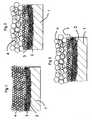
- FIGS. 1 to 3 are diagrams illustrating the microstructure of the electrodes respectively conforming to samples [1], [2] and [3].
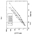
- the polarization resistance of the cathode is determined at from the extrapolation on the axis of the real electrical contributions apparent at medium and low frequencies. These two contributions are generally modelizable by two adjacent or superimposed semicircles, in representation mode of the Nyquist diagrams.
- the samples according to the invention [4], [5] and [6] all operate at 700 ° C, and even for some at a lower temperature, up to 650 ° C, and all have a a very satisfactory specific polarization resistance value, of the order of 1 ⁇ .cm 2 at 800 ° C.
- the samples according to the invention have a stable chemical resistance. This result is based in particular on reactivity tests carried out from the calcination at 800 ° C. under air for 3 weeks of pulverulent mixing of the YSZ oxides, electrolyte material, and mixed oxides of the formula (I). No parasite phase was observed following this experiment. In addition, similar tests were performed on layers, and led to the same results. Finally, studies carried out with LBO 4 proton conducting electrolyte materials led to the same results. The analysis of the tested samples was carried out by X-ray diffraction of the powder mixtures and the surfaces of the different layers, as well as by microscopic studies coupled to electron dispersion spectroscopy studies carried out on slices of the electrochemical cells.
- the 1.98 NiO 4 Nd 1.95 NiO 4 deposit process sol-gel sol-gel sol-gel sol-gel sol-gel sol-gel grain size 200 nm 200 nm 200 nm porosity 10% 10% 10% thickness 300 nm 300 nm 300 nm intermediate layer
- the 4 Ni 3 O 10 The 4 Ni 3 O 10 The 2 NiO 4 - - -
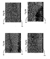
- FIGS 5a, 5b, 5c, 5d represent electron microscopic photographs of different parts of the sample [4] according to the invention.
- the Figures 5a, 5b, 5c represent the interface between the first layer 2 and the last layer 4 superimposed on it with variable magnification (x 2000, x 5000, and x 10 000 respectively).
- the figure 5d shows the interface between the electrolyte 1 and the first layer 2.
- the first layer 2 is porous, but less porous than the last layer 4. It is further noted that the various structural characteristics mentioned above are well obtained.
- the invention can be subject to many different embodiments with respect to the only embodiments described and shown in the figures.
- the number of layers can vary.
Landscapes
- Chemical & Material Sciences (AREA)
- Organic Chemistry (AREA)
- Chemical Kinetics & Catalysis (AREA)
- Electrochemistry (AREA)
- Inorganic Chemistry (AREA)
- General Chemical & Material Sciences (AREA)
- Geology (AREA)
- Engineering & Computer Science (AREA)
- Life Sciences & Earth Sciences (AREA)
- Composite Materials (AREA)
- Materials Engineering (AREA)
- General Life Sciences & Earth Sciences (AREA)
- Physics & Mathematics (AREA)
- Thermal Sciences (AREA)
- Manufacturing & Machinery (AREA)
- Inert Electrodes (AREA)
- Steroid Compounds (AREA)
- Battery Electrode And Active Subsutance (AREA)
- Fuel Cell (AREA)
Abstract
Description
L'invention concerne une électrode à gaz comprenant une pluralité de couches empilées les unes sur les autres à partir d'un substrat solide tel qu'un électrolyte solide, les différentes couches étant adaptées pour permettre le passage d'espèces réactives à travers l'épaisseur de cette électrode, et comprenant une première couche en contact avec ledit substrat solide et une dernière couche présentant une surface libre externe destinée à être placée en contact avec un gaz, notamment avec une source d'oxygène gazeux telle que l'air ambiant. Une telle électrode à gaz -notamment à air- est en particulier applicable pour former une électrode -notamment la cathode- d'une cellule électrolytique, notamment une cellule électrochimique à électrolyte solide (dite SOEC), et en particulier une cellule de pile à combustible à oxyde solide (dite SOFC). Elle est également applicable dans la réalisation d'une membrane électrochimique.The invention relates to a gas electrode comprising a plurality of layers stacked on each other from a solid substrate such as a solid electrolyte, the different layers being adapted to allow the passage of reactive species through the thickness of this electrode, and comprising a first layer in contact with said solid substrate and a last layer having an external free surface intended to be placed in contact with a gas, in particular with a source of oxygen gas such as ambient air. Such a gas electrode - particularly with air - is in particular applicable to form an electrode - in particular the cathode - of an electrolytic cell, in particular a solid electrolyte electrochemical cell (SOEC), and in particular a fuel cell. solid oxide (so-called SOFC). It is also applicable in the production of an electrochemical membrane.
Les piles à combustible sont des dispositifs de production d'énergie extrêmement prometteurs, mais dont l'optimisation technologique reste à réaliser pour permettre leur diffusion à une grande échelle, notamment dans des applications pour le grand public, en particulier dans le domaine des transports ou des locaux d'habitation ou industriels. L'un des problèmes qui se pose avec ces dispositifs est en particulier celui de la réalisation d'électrodes performantes à des températures raisonnables (typiquement inférieures à 800° C), stables dans le temps et présentant une résistance de polarisation aussi faible que possible, en tout cas suffisamment faible pour permettre l'obtention d'un rendement électrique acceptable. De surcroît, cet objectif doit être atteint avec l'utilisation de techniques de fabrication compatibles, en terme de rentabilité et de faisabilité, avec une exploitation à l'échelle industrielle.Fuel cells are extremely promising energy production devices, but their technological optimization has yet to be achieved to enable their wide dissemination, particularly in applications for the general public, particularly in the field of transport or transportation. residential or industrial premises. One of the problems that arises with these devices is in particular that of achieving efficient electrodes at reasonable temperatures (typically below 800 ° C.), stable over time and having a polarization resistance as low as possible, in any case sufficiently weak to allow obtaining an acceptable electrical efficiency. Moreover, this objective must be achieved with the use of compatible manufacturing techniques, in terms of profitability and feasibility, with exploitation on an industrial scale.
C'est pourquoi ces piles à combustible, et en particulier les électrodes à gaz qui les constituent, ont fait récemment l'objet de nombreuses recherches.This is why these fuel cells, and in particular the gas electrodes that constitute them, have recently been the subject of much research.
Par exemple, il a déjà été proposé des solutions visant à améliorer l'interface entre l'électrode à air et l'électrolyte et/ou pour prendre en compte les différences de composition et de coefficient de dilatation thermique entre les matériaux constitutifs de l'électrolyte et de l'électrode.For example, solutions have already been proposed to improve the interface between the air electrode and the electrolyte and / or to take into account the differences in composition and coefficient of thermal expansion between the constituent materials of the electrolyte and electrode.
Les matériaux les plus communément envisagés pour réaliser une telle électrode à air sont des céramiques poreuses à base d'oxyde de structure pérovskite, par exemple les manganites de lanthane dopés au strontium LSM (
Par ailleurs,
Néanmoins, malgré toutes ces recherches, aucune solution n'a encore été proposée permettant d'obtenir des valeurs de résistance de polarisation et de durée de vie acceptables, notamment avec un domaine de température de fonctionnement compris entre 400° C et 800° C.Nevertheless, despite all this research, no solution has yet been proposed to obtain acceptable polarization resistance values and lifetime, especially with an operating temperature range between 400 ° C and 800 ° C.
L'invention vise donc à résoudre ce problème en proposant une électrode à gaz présentant une résistance de polarisation et une durée de vie améliorées, notamment pour une gamme de températures de fonctionnement comprises entre 400° C et 800° C.The invention therefore aims to solve this problem by proposing a gas electrode having improved polarization resistance and service life, especially for a range of operating temperatures between 400 ° C and 800 ° C.
En particulier, l'invention vise à proposer une électrode à gaz présentant, pour une température de fonctionnement inférieure à 800 °C - notamment comprise entre 650 °C et 800 °C-, une résistance de polarisation inférieure à 5 Ω.cm2.In particular, the invention aims to provide a gas electrode having, for an operating temperature of less than 800 ° C., in particular between 650 ° C. and 800 ° C., a polarization resistance of less than 5 Ω.cm 2 .
Plus particulièrement, l'invention vise à proposer une telle électrode à gaz dont les coûts et les techniques de fabrication sont compatibles avec une exploitation à l'échelle industrielle.More particularly, the invention aims to provide such a gas electrode whose costs and manufacturing techniques are compatible with industrial scale operation.
L'invention vise également à proposer un procédé de fabrication d'une telle électrode, ainsi qu'une cellule électrochimique incorporant une telle électrode, et présentant les mêmes avantages.The invention also aims at providing a method for manufacturing such an electrode, as well as an electrochemical cell incorporating such an electrode, and having the same advantages.
A cet effet, l'invention concerne une électrode à gaz comprenant une pluralité de couches empilées les unes sur les autres à partir d'un substrat solide tel qu'un électrolyte solide, les différentes couches étant adaptées pour permettre le passage d'espèces réactives à travers l'épaisseur de cette électrode, et comprenant une première couche en contact avec ledit substrat solide et une dernière couche présentant une surface libre externe destinée à être placée en contact avec un gaz, chacune desdites couches étant constituée d'au moins un oxyde mixte,
caractérisée en ce que :
- chacune desdites couches est constituée d'au moins un oxyde mixte choisi dans le groupe formé des pérovskites, et des phases de Ruddlesden-Popper répondant à la formule générale (I) suivante :

où L est un élément choisi dans le groupe des terres rares, Ni représente le nickel, M est un métal de transition, n est un nombre entier non nul, x, y et δ sont des nombres réels satisfaisant les relations suivantes :


- ladite première couche est constituée d'au moins un oxyde mixte choisi dans le groupe des phases de Ruddlesden-Popper répondant à la formule (I),
- la microstructure de ladite première couche est différente de la microstructure de ladite dernière couche,
- la porosité des différentes couches augmente depuis ladite première couche dont la porosité est la plus faible jusqu'à ladite dernière couche dont la porosité est la plus importante,
- les différentes couches empilées les unes sur les autres forment un réseau de matière solide interconnectée entre la surface libre externe de la dernière couche et le substrat solide, en présentant une épaisseur totale supérieure à 1 µm.
characterized in that
- each of said layers consists of at least one mixed oxide selected from the group consisting of perovskites, and Ruddlesden-Popper phases corresponding to the following general formula (I):
where L is a member selected from the rare earth group, Ni is nickel, M is a transition metal, n is a nonzero integer, x, y and δ are real numbers satisfying the following relationships: - said first layer consists of at least one mixed oxide chosen from the group of Ruddlesden-Popper phases corresponding to formula (I),
- the microstructure of said first layer is different from the microstructure of said last layer,
- the porosity of the various layers increases from said first layer whose porosity is the lowest to said last layer whose porosity is the largest,
- the different layers stacked one on the other form a network of solid material interconnected between the outer free surface of the last layer and the solid substrate, having a total thickness greater than 1 micron.
Une électrode selon l'invention se distingue ainsi de l'état de la technique en particulier par le choix des matériaux constitutifs des couches qui la constituent. Les inventeurs ont en effet constaté que cette famille spécifique de matériaux permet en pratique d'obtenir des résultats étonnamment supérieurs aux autres matériaux plus ou moins similaires envisagés jusqu'à présent dans le cadre de la réalisation d'une électrode à gaz, et ce sans qu'aucune explication scientifique précise ne puisse être donnée à ces résultats surprenants.An electrode according to the invention thus differs from the state of the art in particular by the choice of the constituent materials of the layers that constitute it. The inventors have indeed found that this specific family of materials makes it possible in practice to obtain surprisingly superior results to other more or less similar materials envisaged up to now in the context of the realization of a gas electrode, and without that no precise scientific explanation can be given to these surprising results.
En outre, une électrode selon l'invention se distingue également par le fait que les différentes couches qui la constituent présentent une microstructure hétérogène, c'est-à-dire qui varie d'une couche à l'autre. En particulier, avantageusement et selon l'invention, la microstructure de la première couche est différente de celle de la couche superposée au contact de cette première couche. Cette différence de microstructures provient notamment du fait que les couches sont réalisées par des procédés de dépôts distincts, avec des matériaux qui, bien qu'appartenant à la même famille (formule (I) mentionnée ci-dessus), sont différents (notamment du fait de proportions différentes pour les différents éléments constitutifs du matériau), et avec des paramètres également distincts en termes d'épaisseur, de tailles des grains de matériau déposé, de tailles des pores... En particulier, dans une électrode selon l'invention, la première couche présente avantageusement des caractéristiques macroscopiques qui se situent à l'échelle nanométrique (c'est-à-dire avec des dimensions comprises entre 1 nm et 1000 nm), tandis que la dernière couche, et plus particulièrement toutes les couches superposées à la première couche, présentent des caractéristiques macroscopiques qui se situent à l'échelle micrométrique (c'est-à-dire avec des dimensions comprises entre 1 µm et 1000 µm). En particulier, dans une électrode selon l'invention, la microstructure des différentes couches est telle que la porosité augmente depuis la première couche jusqu'à la dernière couche. Malgré cela, les différentes couches empilées forment un réseau de matière solide interconnectée entre la surface libre externe de la dernière couche et le substrat solide, de sorte que les espèces ioniques et les électrons peuvent circuler au contact de ce réseau en traversant l'épaisseur de l'électrode.In addition, an electrode according to the invention is also distinguished by the fact that the various layers that constitute it have a heterogeneous microstructure, that is to say that varies from one layer to another. In particular, advantageously and according to the invention, the microstructure of the first layer is different from that of the superimposed layer in contact with this first layer. This difference in microstructures stems in particular from the fact that the layers are made by distinct deposition processes, with materials which, although belonging to the same family (formula (I) mentioned above), are different (in particular because of different proportions for the different constituent elements of the material), and with parameters also distinct in terms of thickness, size of the grains of deposited material, pore sizes, etc. In particular, in an electrode according to the invention, the first layer advantageously has macroscopic characteristics which are at the nanoscale (that is to say with dimensions of between 1 nm and 1000 nm), while the last layer, and more particularly all the layers superimposed on the first layer, have macroscopic characteristics which are at the micrometer scale (that is to say with dimensions between 1 μm and 1000 μm). In particular, in an electrode according to the invention, the microstructure of the different layers is such that the porosity increases from the first layer to the last layer. Despite this, the various stacked layers form a network of solid material interconnected between the outer free surface of the last layer and the solid substrate, so that the ionic species and the electrons can circulate in contact with this network while crossing the thickness of the electrode.
Cette combinaison de caractéristiques particulières permet d'obtenir des résultats inédits, notamment en termes de résistance de polarisation à basse température, c'est-à-dire à une température comprise entre 400°C et 800°C.This combination of particular characteristics makes it possible to obtain novel results, especially in terms of low-temperature polarization resistance, that is to say at a temperature of between 400 ° C. and 800 ° C.
Une électrode selon l'invention est également avantageusement caractérisée par tout ou partie des caractéristiques suivantes :
- ladite dernière couche est constituée d'au moins un oxyde mixte choisi dans le groupe formé des pérovskites et des phases de Ruddlesden-Popper répondant à la formule (I), et toutes les autres couches sont constituées d'au moins un oxyde mixte choisi dans le groupe formé des phases de Ruddlesden-Popper répondant à la formule générale (I) ; autrement dit, seule la dernière couche peut être éventuellement formée d'une structure pérovskite ou incorporer au moins un oxyde mixte présentant la structure d'une pérovskite ; en variante, toutes les couches sont constituées d'au moins un oxyde mixte choisi dans le groupe formé des phases de Ruddlesden-Popper répondant à la formule générale (I),
- les éléments L et M sont les mêmes pour toutes lesdites couches de l'électrode,
- la différence de microstructures provient de proportions différentes pour les différents éléments constitutifs du matériau, c'est-à-dire que les valeurs des paramètres n, x, y et δ de la formule (I) varient d'une couche à l'autre (que les éléments L et M soient le même ou non) ; de préférence, les éléments L et M sont les mêmes pour toutes lesdites couches de l'électrode et les valeurs des paramètres n, x, y et δ de la formule (I) varient d'une couche à l'autre ;
- L est un élément choisi dans le groupe formé de La, Pr, Nd, Sm, Eu, Er, et Gd, et M est un métal de transition choisi dans le groupe formé de Fe, Co, et Mn,
- ladite première couche est constituée d'au moins un oxyde mixte choisi dans le groupe des phases de Ruddlesden-Popper répondant à la formule (I) avec n-x ≠ 1,
- pour ladite première couche, on a (n+1-x) /(n-y) < 2,
- ladite première couche est constituée d'un oxyde mixte de formule L 2- xNiO 4+δ , L étant choisi dans le groupe formé de La, Pr, Nd,
- ladite dernière couche est constituée d'un oxyde mixte choisi dans le groupe formé de LNiO3, L 2-x NiO 4+δ, L 3 Ni 2 O 7-δ, et L 4 Ni 3 O 10-δ L étant choisi dans le groupe formé de La, Pr, Nd,
- ladite première couche est constituée de particules solides élémentaires reliées en contact les unes avec les autres, la taille moyenne de ces particules élémentaires étant inférieure à 300 nm,
- l'épaisseur de ladite première couche est inférieure à 200 nm -notamment de l'ordre de 50 nm-,
- ladite dernière couche est constituée de particules solides élémentaires formant entre elles des pores ouverts et constituant un réseau interconnecté de matière solide à travers toute son épaisseur,
- ladite dernière couche est constituée de particules solides élémentaires reliées en contact les unes avec les autres, la taille moyenne de ces particules élémentaires étant comprise entre 100 nm et 5 µm,
- elle comprend entre deux et cinq couches empilées sur le substrat solide, les différentes couches empilées présentant une épaisseur totale comprise entre 1 µm et 15 µm,
- ladite première couche présente une porosité inférieure à 10 % en volume,
- ladite dernière couche présente une porosité supérieure à 10 % et inférieure à 50 % en volume,
- elle présente une pluralité de couches superposées à ladite première couche en contact avec le substrat solide, et dont la porosité est croissante depuis ladite première couche jusqu'à ladite dernière couche,
- chacune desdites couches résulte d'au moins un dépôt choisi parmi un dépôt de barbotine, un dépôt de sol chargé, et un dépôt sol-gel,
- au moins une couche intermédiaire entre ladite première couche et ladite dernière couche résulte d'au moins un dépôt choisi parmi un dépôt de barbotine et un dépôt de sol chargé,
- ladite première couche résulte d'au moins un dépôt sol-gel,
- ladite dernière couche résulte d'au moins un dépôt choisi parmi un dépôt de barbotine et un dépôt de sol chargé,
- parmi les différentes couches, ladite première couche présente la plus grande conductivité ionique,
- ladite première couche est formée d'un matériau dont la conductivité ionique est supérieure ou égale à 10-2 S.cm-1,
- ladite dernière couche est formée d'un matériau dont la conductivité ionique est supérieure à 10-4 S.cm-1, et dont la conductivité électronique est supérieure à 50 S.cm-1.
- said last layer consists of at least one mixed oxide chosen from the group consisting of perovskites and Ruddlesden-Popper phases corresponding to formula (I), and all the other layers consist of at least one mixed oxide selected from the group consisting of Ruddlesden-Popper phases having the general formula (I); in other words, only the last layer may be optionally formed of a perovskite structure or incorporate at least one mixed oxide having the structure of a perovskite; alternatively, all the layers consist of at least one mixed oxide chosen from the group formed by the Ruddlesden-Popper phases corresponding to the general formula (I),
- the elements L and M are the same for all said layers of the electrode,
- the difference in microstructures comes from different proportions for the different constituent elements of the material, that is to say that the values of the parameters n, x, y and δ of the formula (I) vary from one layer to another (whether the elements L and M are the same or not); preferably, the elements L and M are the same for all said layers of the electrode and the values of the parameters n, x, y and δ of the formula ( I ) vary from one layer to another;
- L is a member selected from the group consisting of La, Pr, Nd, Sm, Eu, Er, and Gd, and M is a transition metal selected from the group consisting of Fe, Co, and Mn,
- said first layer consists of at least one mixed oxide chosen from the group of Ruddlesden-Popper phases corresponding to formula (I) with nx ≠ 1,
- for said first layer, we have (n + 1-x) / (ny) <2,
- said first layer consists of a mixed oxide of formula L 2 x NiO 4+ δ , L being chosen from the group consisting of La, Pr, Nd,
- said last layer consists of a mixed oxide selected from the group consisting of LNiO 3 , L 2-x NiO 4 + δ , L 3 Ni 2 O 7 -δ , and L 4 Ni 3 O 10 -δ L being chosen from the group formed by La, Pr, Nd,
- said first layer consists of connected elementary solid particles in contact with each other, the average size of these elementary particles being less than 300 nm,
- the thickness of said first layer is less than 200 nm, in particular of the order of 50 nm,
- said last layer is constituted by elementary solid particles forming between them open pores and constituting an interconnected network of solid material throughout its entire thickness,
- said last layer consists of connected elementary solid particles in contact with each other, the average size of these elementary particles being between 100 nm and 5 μm,
- it comprises between two and five layers stacked on the solid substrate, the various stacked layers having a total thickness of between 1 μm and 15 μm,
- said first layer has a porosity of less than 10% by volume,
- said last layer has a porosity greater than 10% and less than 50% by volume,
- it has a plurality of layers superimposed on said first layer in contact with the solid substrate, and whose porosity is increasing from said first layer to said last layer,
- each of said layers results from at least one deposit selected from a slip deposit, a loaded soil deposit, and a sol-gel deposit,
- at least one intermediate layer between said first layer and said last layer results from at least one deposit selected from a slip deposit and a loaded soil deposit,
- said first layer results from at least one sol-gel deposit,
- said last layer results from at least one deposit selected from a slip deposit and a loaded soil deposit,
- among the different layers, said first layer has the highest ionic conductivity,
- said first layer is formed of a material whose ionic conductivity is greater than or equal to 10 -2 S.cm -1 ,
- said last layer is formed of a material whose ionic conductivity is greater than 10 -4 S.cm -1 , and whose electronic conductivity is greater than 50 S.cm -1 .
L'invention s'étend à un procédé de fabrication d'une électrode selon l'invention. L'invention concerne ainsi un procédé de fabrication d'une électrode à gaz dans lequel on empile une pluralité de couches les unes sur les autres à partir d'un substrat solide tel qu'un électrolyte solide, les différentes couches étant réalisées pour permettre le passage d'espèces réactives à travers l'épaisseur de cette électrode, et comprenant une première couche en contact avec ledit substrat solide et une dernière couche présentant une surface libre externe destinée à être placée en contact avec un gaz, chacune desdites couches étant constituée d'au moins un oxyde mixte, caractérisé en ce que :
- on réalise chacune desdites couches de façon à ce qu'elle soit constituée d'au moins un oxyde mixte choisi dans le groupe formé des pérovskites, et des phases de Ruddlesden-Popper répondant à la formule générale (I) suivante :

où L est un élément choisi dans le groupe des terres rares, Ni représente le nickel, M est un métal de transition, n est un nombre entier non nul, x, y et δ sont des nombres réels satisfaisant les relations suivantes :


- ladite première couche est réalisée de façon à être constituée d'au moins un oxyde mixte choisi dans le groupe des phases de Ruddlesden-Popper répondant à la formule (I),
- on réalise ladite première couche selon un procédé de dépôt différent du procédé de dépôt avec lequel on réalise ladite dernière couche, de sorte que :
- la microstructure de ladite première couche est différente de la microstructure de ladite dernière couche,
- la porosité des différentes couches augmente depuis ladite première couche dont la porosité est la plus faible jusqu'à ladite dernière couche dont la porosité est la plus importante,
- on réalise les différentes couches empilées de telle façon qu'elles forment un réseau de matière solide interconnectée entre la surface libre externe de la dernière couche et le substrat solide, en présentant une épaisseur totale supérieure à 1 µm.
- each of said layers is produced so that it consists of at least one mixed oxide chosen from the group formed by perovskites, and Ruddlesden-Popper phases corresponding to the following general formula (I):
where L is a member selected from the rare earth group, Ni is nickel, M is a transition metal, n is a nonzero integer, x, y and δ are real numbers satisfying the following relationships: - said first layer is made to consist of at least one mixed oxide chosen from the group of Ruddlesden-Popper phases corresponding to formula (I),
- said first layer is produced according to a deposition process different from the deposition method with which said last layer is produced, so that:
- the microstructure of said first layer is different from the microstructure of said last layer,
- the porosity of the various layers increases from said first layer whose porosity is the lowest to said last layer whose porosity is the largest,
- the various stacked layers are made in such a way that they form a network of solid material interconnected between the outer free surface of the last layer and the solid substrate, having a total thickness greater than 1 μm.
Avantageusement dans un procédé selon l'invention, on réalise chacune des couches de l'électrode, notamment ladite première couche et/ou ladite dernière couche, de façon à ce qu'elle soit conforme à tout ou partie des caractéristiques mentionnées ci-dessus.Advantageously, in a method according to the invention, each of the layers of the electrode, in particular said first layer and / or said last layer, is produced so that it complies with all or some of the characteristics mentioned above.
En particulier, avantageusement et selon l'invention, on réalise ladite première couche avec un procédé de dépôt différent du procédé de dépôt de la couche superposée au contact de cette première couche. On dépose ladite première couche sur le substrat solide par au moins un dépôt sol-gel dans lequel on mélange dans un solvant des espèces précurseurs destinées à former au moins un oxyde mixte, puis on mélange la suspension à une matrice polymère organique, puis on applique ce mélange sur le substrat solide, puis on soumet l'ensemble à un traitement thermique adapté pour entraîner la cristallisation de chaque oxyde mixte et la décomposition de la matrice polymère organique.In particular, advantageously and according to the invention, said first layer is produced with a deposition method different from the deposition method of the superimposed layer in contact with this first layer. Said first layer is deposited on the solid substrate by at least one sol-gel deposit in which precursor species intended to form at least one mixed oxide are mixed in a solvent, and the suspension is then mixed with an organic polymer matrix, and then applied this mixture on the solid substrate, then the whole is subjected to a heat treatment adapted to cause the crystallization of each mixed oxide and the decomposition of the organic polymer matrix.
Également, avantageusement et selon l'invention, on applique ladite dernière couche en réalisant au moins un dépôt de barbotine dans lequel on réalise une barbotine contenant des particules solides d'au moins un oxyde mixte dispersées dans un milieu liquide, puis on applique cette barbotine sous forme d'au moins une couche, puis on soumet l'ensemble à un traitement adapté pour entraîner l'évacuation du milieu liquide. Ainsi, dans cette variante de l'invention, on applique ladite dernière couche par un dépôt de barbotine.Also, advantageously and according to the invention, said last layer is applied by producing at least one slip deposit in which a slip is produced containing solid particles of at least one mixed oxide dispersed in a liquid medium, and then this slip is applied. in the form of at least one layer, then the whole is subjected to a treatment adapted to cause the evacuation of the liquid medium. Thus, in this variant of the invention, said last layer is applied by a slip deposit.
En variante, on peut aussi appliquer ladite dernière couche par un dépôt de sol chargé. Pour ce faire, avantageusement et selon l'invention on applique ladite dernière couche en réalisant au moins un dépôt de sol chargé dans lequel on réalise une suspension contenant des particules solides dispersées dans un milieu liquide contenant des précurseurs d'espèces destinées à former au moins un oxyde mixte, puis on applique cette suspension sous forme d'au moins une couche, puis on soumet l'ensemble à un traitement adapté pour entraîner le dépôt et la cristallisation des oxydes mixtes et l'évacuation de la phase liquide.Alternatively, one can also apply said last layer by a loaded soil deposit. To do this, advantageously and according to the invention, said last layer is applied by producing at least one loaded soil deposit in which a suspension is produced containing solid particles dispersed in a liquid medium containing precursors of species intended to form at least a mixed oxide, then this suspension is applied in the form of at least one layer, then the whole is subjected to a suitable treatment to cause the deposition and crystallization of the mixed oxides and the evacuation of the liquid phase.
Avantageusement et selon l'invention, on applique chaque couche intermédiaire entre ladite première couche et ladite dernière couche en réalisant au moins un dépôt de barbotine et/ou au moins un dépôt de sol chargé comme indiqué ci-dessus. De préférence, on applique chaque couche superposée à ladite première couche jusqu'à la dernière couche en utilisant le même procédé de dépôt (barbotine ou sol chargé).Advantageously and according to the invention, each intermediate layer is applied between said first layer and said last layer by producing at least one slip deposit and / or at least one loaded soil deposit as indicated above. Preferably, each layer superimposed on said first layer is applied to the last layer using the same deposition method (slip or loaded soil).
Par ailleurs, avantageusement et selon l'invention, le substrat solide est un électrolyte solide étanche aux gaz (non poreux), choisi dans le groupe constitué des céramiques conductrices des anions O2- et des céramiques conductrices des protons.Furthermore, advantageously and according to the invention, the solid substrate is a gas-tight (non-porous) solid electrolyte selected from the group consisting of conductive ceramics of O 2 anions and proton conducting ceramics.
Les oxydes mixtes répondant à la formule (I) sont des phases de la série de Ruddlesden-Popper (Ln+1NinO3n+1). Les phases de Ruddlesden-Popper sont bien connues (cf. par exemple la publication
Les inventeurs ont maintenant constaté avec surprise que l'utilisation de tels oxydes mixtes choisis dans le groupe formé des pérovskites, et des phases de Ruddlesden-Popper conformes à la formule (I), permet en pratique de réaliser une électrode formée de différentes couches empilées comme indiqué ci-dessus, et ce par des procédés industriels simples et économiques, du type dépôt sol-gel et/ou dépôt de barbotine et/ou dépôt de sol chargé, tout en contrôlant précisément :
- la porosité et le gradient de porosité dans l'épaisseur de l'électrode,
- les propriétés de conduction ionique et électronique au sein de l'électrode, et donc ses performances électriques,
- les coefficients de dilatation thermique des différentes couches superposées pour les rendre compatibles les uns avec les autres,
- the porosity and the porosity gradient in the thickness of the electrode,
- the ionic and electronic conduction properties within the electrode, and therefore its electrical performance,
- the coefficients of thermal expansion of the different superimposed layers to make them compatible with each other,
Une électrode conforme à l'invention présente des performances inattendues en terme de stabilité dans le temps et de résistance de polarisation. En particulier, une électrode selon l'invention peut présenter, pour une température de fonctionnement inférieure à 800 °C -notamment comprise entre 650 °C et 800 °C-, une résistance de polarisation inférieure à 5 Ω.cm2 -notamment de l'ordre de 1 Ω.cm2 à 800°C-.An electrode according to the invention has unexpected performance in terms of stability over time and polarization resistance. In particular, an electrode according to the invention may have, for an operating temperature of less than 800 ° C., in particular between 650 ° C. and 800 ° C., a polarization resistance of less than 5 Ω · cm 2, in particular order of 1 Ω.cm 2 at 800 ° C.
L'invention est en particulier avantageusement applicable pour la réalisation d'une électrode à gaz d'une cellule électrochimique. En conséquence, l'invention s'étend à une cellule électrochimique comprenant au moins une électrode à gaz selon l'invention. Plus particulièrement, l'invention s'étend à une cellule électrochimique de pile à combustible caractérisée en ce qu'elle comprend un électrolyte solide portant une cathode formée d'une électrode à air conforme à l'invention.The invention is particularly advantageously applicable for the production of a gas electrode of an electrochemical cell. Accordingly, the invention extends to an electrochemical cell comprising at least one gas electrode according to the invention. More particularly, the invention extends to a fuel cell electrochemical cell characterized in that it comprises a solid electrolyte carrying a cathode formed of an air electrode according to the invention.
Dans une cellule électrochimique selon l'invention, l'électrode à gaz présente une forme globalement plane, ou une forme globalement cylindrique -notamment cylindrique de révolution-, ou toute autre forme.In an electrochemical cell according to the invention, the gas electrode has a generally flat shape, or a generally cylindrical shape - particularly cylindrical in revolution - or any other shape.
D'autres caractéristiques, buts et avantages de l'invention apparaîtront à la lumière de la description suivante qui se réfère aux exemples donnés ci-après et aux figures annexées dans lesquelles :
- la
figure 1 est un schéma illustrant en coupe une électrode à gaz conforme à un premier exemple de réalisation de l'invention, - la
figure 2 est un schéma illustrant en coupe une électrode à gaz conforme à un deuxième exemple de réalisation de l'invention, - la
figure 3 est un schéma illustrant en coupe une électrode à gaz conforme à un troisième exemple de réalisation de l'invention, - la
figure 4 est un diagramme illustrant des valeurs de résistance de polarisation spécifique obtenues avec différents échantillons d'électrodes à gaz conformes à l'invention, - les
figures 5a, 5b, 5c, 5d sont des photographies illustrant à différents grossissements la structure d'une électrode à gaz selon un exemple de réalisation de l'invention.
- the
figure 1 is a diagram illustrating in section a gas electrode according to a first embodiment of the invention, - the
figure 2 is a diagram illustrating in section a gas electrode according to a second embodiment of the invention, - the
figure 3 is a diagram illustrating in section a gas electrode according to a third embodiment of the invention, - the
figure 4 is a diagram illustrating specific polarization resistance values obtained with different samples of gas electrodes according to the invention, - the
Figures 5a, 5b, 5c, 5d are photographs illustrating at different magnifications the structure of a gas electrode according to an exemplary embodiment of the invention.
Une électrode à gaz selon l'invention est constituée d'une pluralité de couches 2, 3, 4 superposées les unes sur les autres à partir d'un substrat solide 1 formé d'une céramique dense.A gas electrode according to the invention consists of a plurality of
La première couche 2 est constituée d'au moins un oxyde mixte choisi dans le groupe formé des phases de Ruddlesden-Popper répondant à la formule générale (I) suivante : ![]()
où L est un élément choisi dans le groupe des terres rares, Ni représente le nickel, M est un métal de transition, n est un nombre entier non nul, x, y et δ sont des nombres réels satisfaisant les relations suivantes : ![]()
![]()
![]()
![]()
where L is a member selected from the rare earth group, Ni is nickel, M is a transition metal, n is a nonzero integer, x , y and δ are real numbers satisfying the following relationships: ![]()
![]()
![]()
Chacune des autres couches 3, 4 est constituée d'au moins un oxyde mixte choisi dans le groupe formé des pérovskites et des phases de Ruddlesden-Popper répondant à la formule générale (I) ci-dessus mentionnée. De préférence, chacune desdites couches 2, 3 est constituée d'au moins un oxyde mixte choisi dans le groupe formé uniquement des phases de Ruddlesden-Popper répondant à la formule (I), à l'exception de la dernière couche 4 qui est constituée d'au moins un oxyde mixte choisi dans le groupe des pérovskites et des phases de Ruddlesden-Popper répondant à la formule (I), c'est-à-dire qui peut comprendre au moins un oxyde mixte choisi dans le groupe des pérovskites.Each of the
La structure cristallographique des phases de Ruddlesden-Popper répondant à la formule (I), qui peut aussi être représentée par (LO) (Ln-xNin-y MyO3)n, est formée de n couches pérovskites d'octaèdres oxygénés Nin-yMyO6. Les atomes d'oxygène forment un feuillet dont la structure est de type NaCl. Le nombre n représente le nombre de couches pérovskites liées entre elles par le sommet des octaèdres, et δ représente le nombre d'atomes d'oxygène interstitiels insérés dans la couche LO (cf. par exemple la publication
Dans une électrode à gaz selon l'invention, la première couche 2 déposée au contact du substrat solide 1 est formée d'un film mince dont la microstructure présente des caractéristiques dimensionnelles qui se situent à l'échelle nanométrique.In a gas electrode according to the invention, the
La dernière couche 4, et de préférence chacune des couches 3, 4 superposées à cette première couche 2, est formée d'une couche plus épaisse réalisée avec un matériau appartenant à la famille mentionnée ci-dessus, mais qui est différente, en ce qui concerne sa microstructure, de la première couche 2. La dernière couche 4, et de préférence chacune des couches 3, 4 superposées à cette première couche 2, est réalisée selon un procédé de dépôt différent, et de façon à présenter une microstructure dont les caractéristiques dimensionnelles se situent à l'échelle micrométrique.The
De préférence, L est un élément choisi dans le groupe formé de La, Pr, Nd, Sm, Eu, Er, et Gd, et M est un métal de transition choisi dans le groupe formé de Fe, Co, et Mn.Preferably, L is a member selected from the group consisting of La, Pr, Nd, Sm, Eu, Er, and Gd, and M is a transition metal selected from the group consisting of Fe, Co, and Mn.
Rien n'empêche cependant de faire varier la nature des éléments L et M d'une couche à l'autre au sein d'une même électrode conforme à l'invention. Néanmoins, avantageusement, dans une électrode selon l'invention, les éléments L et M sont les mêmes pour toutes lesdites couches de l'électrode. Il en résulte en particulier une meilleure affinité chimique, une meilleure compatibilité thermomécanique et moins de problèmes liés aux phénomènes de diffusion des éléments constitutifs de l'électrode les uns dans les autres.Nothing prevents, however, to vary the nature of the elements L and M from one layer to another within the same electrode according to the invention. Nevertheless, advantageously, in an electrode according to the invention, the elements L and M are the same for all said layers of the electrode. This results in particular in a better chemical affinity, a better thermomechanical compatibility and fewer problems related to the phenomena of diffusion of the constituent elements of the electrode into each other.
Le substrat solide 1 est un électrolyte solide dense, c'est-à-dire non poreux et donc étanche aux gaz. Un tel électrolyte solide dense peut être choisi dans le groupe constitué des céramiques conductrices des anions O2- et des céramiques conductrices des protons. Plus particulièrement, le substrat solide 1 est choisi parmi :
- Les matériaux conducteurs protoniques, et en particulier ceux présentant l'une des structures suivantes :
- Structure perovskite AB1-xMxO3:
- o Exemples: Ba(Zr,Yb)O3, Sr(Ce,Y)O3
- Structure brownmillerite : A2B2O5:
- o Exemple: Sr2Gd2O5
- Structure pyrochlore: A2B2O7
- o Exemple: Er2Ti2O7
- Structure monazite: LBO4
- o Exemple: La0.995Sr0.005NbO4
- Structure sesquioxide:
- o Exemple: Er2O3 dopé
- Phosphate: LPO4
- o Exemple: LaPO4
- Structure perovskite AB1-xMxO3:
- les matériaux conducteurs anioniques de l'oxygène, et en particulier ceux présentant l'une des structures suivantes :
- Structure perovskite AB1-xMxO3:
- o Exemple: La0.9Ba0.1Ga0.8Mg0.2O2.85
- Structure brownmillerite A2B2O5:
- o Exemple: Ba2In2O5
- Structure fluorite AO2:
- o Exemple:zircone yttriée : (Zr,Y)O2
- Structure apatite: L10M6O24
- o Exemple: La10Si6O27
- Structure Aurivillius (Bi2O2)(An-1BnOx)
- o Exemples: Bi3Nb0.1Zr0.9O6.55, Bi5TiNbWO15 , Bi4Ti3O12
- Structure L2Mo2O9
- o Exemple: La2Mo2O9
- Structure pyrochlore L2Zr2O7
- Structure perovskite AB1-xMxO3:
- Proton conductive materials, and in particular those having one of the following structures:
- Perovskite AB 1-x M x O 3 structure :
- o Examples: Ba (Zr, Yb) O 3 , Sr (Ce, Y) O 3
- Brownmillerite structure: A 2 B 2 O 5 :
- o Example: Sr 2 Gd 2 O 5
- Pyrochlore structure: A 2 B 2 O 7
- o Example: Er 2 Ti 2 O 7
- Monazite structure: LBO 4
- o Example: The 0.995 Sr 0.005 NbO 4
- Sesquioxide structure:
- o Example: doped Er 2 O 3
- Phosphate: LPO 4
- o Example: LaPO 4
- Perovskite AB 1-x M x O 3 structure :
- anionic oxygen conducting materials, and in particular those having one of the following structures:
- Perovskite AB 1-x M x O 3 structure :
- o Example: The 0.9 Ba 0.1 Ga 0.8 Mg 0.2 O 2.85
- Brownmillerite structure A 2 B 2 O 5 :
- o Example: Ba 2 In 2 O 5
- AO 2 fluorite structure:
- o Example: yttria zirconia: (Zr, Y) O 2
- Apatite structure: L 10 M 6 O 24
- o Example: The 10 Si 6 O 27
- Aurivillius structure (Bi 2 O 2 ) (A n-1 B n O x )
- o Examples: Bi 3 Nb 0.1 Zr 0.9 O 6.55 , Bi 5 TiNbWO 15 , Bi 4 Ti 3 O 12
- Structure L 2 Mo 2 O 9
- o Example: The 2 Mo 2 O 9
- Pyrochlore structure L 2 Zr 2 O 7
- Perovskite AB 1-x M x O 3 structure :
Dans les formules génériques des structures mentionnées ci-dessus, A désigne un élément alcalin ou alcalino-terreux, B et M désignent des métaux de transition appartenant aux groupes 3 à 14 de la classification périodique, et L désigne une terre rare.In the generic formulas of the structures mentioned above, A denotes an alkaline or alkaline-earth element, B and M denote transition metals belonging to
La première couche 2 est réalisée de façon :
- à être constituée de particules solides élémentaires reliées en contact les unes avec les autres, la taille moyenne de ces particules élémentaires étant inférieure à 300 nm,
- et à présenter une épaisseur totale inférieure à 200 nm -typiquement de l'ordre de 50 nm- ; une porosité en volume inférieure à 10 % -typiquement comprise entre 1 % et 5 %- ; et une conductivité ionique supérieure ou égale à 10-2 S.cm-1 -typiquement de l'ordre de 5.10-2 S.cm-1-.
- to consist of connected elementary solid particles in contact with each other, the average size of these elementary particles being less than 300 nm,
- and to have a total thickness of less than 200 nm, typically of the order of 50 nm; a porosity in volume of less than 10% -ypically between 1% and 5%; and an ionic conductivity greater than or equal to 10 -2 S.cm -1 -typically of the order of 5.10 -2 S.cm -1 -.
Pour ce faire, on peut avantageusement utiliser un procédé de dépôt de type sol-gel. Dans un tel procédé, on mélange dans un milieu liquide neutre des précurseurs des espèces aptes à former au moins un oxyde mixte, puis on mélange cette suspension à une matrice polymère organique, puis on applique ce mélange sur le substrat solide, puis on soumet l'ensemble à un traitement thermique adapté pour entraîner la cristallisation de chaque oxyde mixte et la décomposition de la matrice polymère organique. Avec un tel procédé, on peut en particulier ajuster la porosité de la couche obtenue en faisant varier la proportion de matrice polymère organique par rapport aux précurseurs inorganiques. Typiquement, le rapport molaire entre la quantité de matrice polymère organique sur la quantité des précurseurs inorganiques est compris entre quatre et six. La concentration des précurseurs utilisés dans la suspension initiale permet par ailleurs de contrôler l'épaisseur totale de la couche formée. En pratique, ce procédé peut être mis en oeuvre par toute technique connue, de préférence selon la technique dite de revêtement par trempage («dip-coating») dans laquelle le substrat solide est plongé dans le mélange liquide, puis extrait de ce mélange avec une vitesse - contrôlée, puis soumis à un traitement thermique à haute température, généralement supérieure à 700°C.To do this, it is advantageous to use a sol-gel type deposition process. In such a process, precursors of the species capable of forming at least one mixed oxide are mixed in a neutral liquid medium, and this suspension is then mixed with an organic polymer matrix, and this mixture is then applied to the solid substrate, and the mixture is then subjected to together with a heat treatment adapted to cause the crystallization of each mixed oxide and the decomposition of the organic polymer matrix. With such a method, it is possible in particular to adjust the porosity of the layer obtained by varying the proportion of organic polymer matrix relative to the inorganic precursors. Typically, the molar ratio between the amount of organic polymer matrix on the amount of inorganic precursors is between four and six. The concentration of the precursors used in the initial suspension also makes it possible to control the total thickness of the layer formed. In practice, this process can be carried out by any known technique, preferably by the so-called dip-coating technique in which the solid substrate is immersed in the liquid mixture and then extracted from this mixture with a speed - controlled, then subjected to a heat treatment at high temperature, generally greater than 700 ° C.
En outre, pour réaliser cette première couche 2, on utilise de préférence un matériau constitué d'au moins un oxyde mixte choisi dans le groupe des phases de Ruddlesden-Popper répondant à la formule (I) avec n-x ≠ 1. Plus particulièrement, on choisit ledit matériau de telle sorte que (n+1-x) /(n-y) < 2.In addition, to produce this
D'excellents résultats ont été obtenus avec une première couche 2 constituée d'un oxyde mixte de formule L2-xNiO4+δ, L étant choisi dans le groupe formé de La, Pr, Nd.Excellent results have been obtained with a
Au moins une autre couche différente 3, 4 est superposée à cette première couche 2. Le nombre de couches superposées peut être variable. Les inventeurs ont cependant constaté qu'à partir d'un nombre de couches superposées supérieur à cinq, les performances de l'électrode ne sont pas sensiblement améliorées. En conséquence, une électrode selon l'invention comprend avantageusement un nombre total de couches superposées sur le substrat solide compris entre deux et cinq.At least one other
Quoi qu'il en soit, les différentes couches 3, 4 superposées à la première couche 2 sont constituées d'un matériau correspondant à la même famille (formule (I)), de préférence avec des éléments L et M identiques dans toutes les couches de la même électrode, mais uniquement en faisant varier éventuellement, d'une couche à l'autre, les proportions des différents éléments dans la formule (I), c'est-à-dire les valeurs des paramètres n, x, y et δ de la formule (I).Anyway, the
En outre, les différentes couches 3, 4 superposées à la première couche 2 présentent une microstructure différente de celle de la première couche 2. Cette variation de microstructures peut résulter en particulier de l'utilisation d'un procédé de dépôt différent. Les inventeurs ont en effet constaté que les matériaux répondant à la formule (I) peuvent être déposés selon différents procédés, et que le choix du procédé utilisé pour le dépôt permet de faire varier la microstructure et en particulier la porosité et les propriétés de conduction électronique et ionique de chaque couche déposée.In addition, the
En particulier, la dernière couche 4 de l'électrode qui vient au contact du gaz, notamment de l'air, est réalisée de façon à être constituée de particules solides élémentaires formant entre elles des pores ouverts et constituant un réseau interconnecté de matière solide à travers toute son épaisseur, ces particules solides élémentaires étant reliées en contact les unes avec les autres avec une taille moyenne des particules élémentaires comprise entre 100 nm et 5 µm - typiquement de l'ordre de 1 µm-.In particular, the
L'épaisseur de la dernière couche 4 est avantageusement comprise entre 1 µm et 5 µm.The thickness of the
De même, l'épaisseur de chaque couche intermédiaire 3 superposée à la première couche 2 est avantageusement comprise entre 1 µm et 5 µm.Likewise, the thickness of each
L'épaisseur des différentes couches de l'électrode, et en particulier de la dernière couche 4 et de chaque couche intermédiaire 3 superposée à la première couche 2, est ajustée de façon à obtenir une épaisseur totale de l'électrode appropriée.The thickness of the different layers of the electrode, and in particular of the
Cette épaisseur totale de l'électrode doit être suffisante d'une part pour permettre une activité électrocatalytique suffisante (cette activité dépendant de la quantité de matière au contact de laquelle les espèces réactives peuvent venir), d'autre part pour présenter une bonne tenue thermomécanique et éviter les courts-circuits en fonctionnement. Pour ce faire, l'épaisseur totale de l'électrode est supérieure à 1 µm, et de préférence supérieure à 5 µm. A l'inverse, l'épaisseur totale de l'électrode doit être aussi faible que possible pour présenter une résistivité qui n'est pas trop élevée et pour limiter les coûts de fabrication.This total thickness of the electrode must be sufficient on the one hand to allow sufficient electrocatalytic activity (this activity depends on the amount of material in contact with which the reactive species may come), on the other hand to have a good thermomechanical behavior and avoid short circuits during operation. To do this, the total thickness of the electrode is greater than 1 micron, and preferably greater than 5 microns. Conversely, the total thickness of the electrode should be as low as possible to have a resistivity that is not too high and to limit manufacturing costs.
L'invention permet de satisfaire à l'ensemble de ces conditions, avec une électrode dont l'épaisseur est comprise entre 1 µm et 15 µm.The invention makes it possible to satisfy all of these conditions with an electrode whose thickness is between 1 μm and 15 μm.
Ainsi, l'épaisseur totale de l'électrode selon l'invention est de préférence comprise entre 1 µm et 15 µm.Thus, the total thickness of the electrode according to the invention is preferably between 1 μm and 15 μm.
La porosité en volume de la dernière couche 4 est comprise entre 10 % et 50 % -typiquement de l'ordre de 30 %-. La dernière couche 4 est par ailleurs réalisée de façon à présenter une conductivité ionique supérieure à 10-4 S.cm-1, et une conductivité électronique supérieure à 50 S.cm-1.The volume porosity of the
Pour obtenir de telles caractéristiques structurelles, on peut en particulier réaliser la dernière couche 4 par un dépôt de barbotine, c'est-à-dire en réalisant une barbotine contenant des particules d'oxyde(s) mixte(s) dispersées en suspension dans un milieu liquide, en appliquant cette barbotine sous forme d'une couche, puis en soumettant l'ensemble à un traitement -notamment un traitement thermique- adapté pour entraîner l'évacuation du milieu liquide. Un tel dépôt de suspension chargée en particules d'oxyde(s) mixte(s) peut être réalisé en pratique selon différentes techniques connues en elles-mêmes, par exemple le revêtement par trempage («dip-coating»), le revêtement en rotation («spin-coating»), le coulage en bande,...To obtain such structural characteristics, it is possible in particular to produce the
Le milieu liquide utilisé pour réaliser la barbotine peut être un solvant aqueux ou un solvant organique (par exemple choisi parmi un alcool, une cétone,...). Les particules solides de chaque oxyde mixte peuvent être elles-mêmes obtenues par voie sol-gel, en préparant une suspension de sels des espèces précurseurs dans un solvant, en ajoutant une matrice polymère organique dans cette suspension, puis en soumettant l'ensemble à un traitement thermique à une température comprise entre 700° C et 1000° C. Le choix de la température permet en particulier d'influencer la taille des particules d'oxyde(s) obtenues.The liquid medium used to make the slip may be an aqueous solvent or an organic solvent (for example chosen from an alcohol, a ketone, etc.). The solid particles of each mixed oxide can themselves be obtained by sol-gel, by preparing a salt suspension of the precursor species in a solvent, by adding an organic polymer matrix in this suspension, and then subjecting the assembly to a heat treatment at a temperature between 700 ° C and 1000 ° C. The choice of temperature in particular allows to influence the size of the oxide particles (s) obtained.
Les particules obtenues sont dispersées dans le solvant liquide pour former la barbotine. Avantageusement, on ajoute également une certaine proportion minoritaire d'au moins un agent porogène, par exemple choisi parmi l'amidon, le carbone, un composé fluorocarboné (par exemple PTFE)... Un tel agent porogène inerte est également éliminé lors de la phase subséquente de traitement thermique.The particles obtained are dispersed in the liquid solvent to form the slip. Advantageously, a certain minority proportion of at least one porogenic agent is also added, for example chosen from starch, carbon, a fluorocarbon compound (for example PTFE), etc. Such an inert pore-forming agent is also removed during the subsequent heat treatment phase.
Le traitement d'élimination du milieu liquide de la suspension peut être une calcination haute température, typiquement de l'ordre de 1000° C. Rien n'empêche également, en variante ou en combinaison, d'employer tout autre traitement d'élimination, par exemple par évaporation.The elimination treatment of the liquid medium from the suspension may be a high temperature calcination, typically of the order of 1000 ° C. Nothing also prevents, alternatively or in combination, to use any other elimination treatment, for example by evaporation.
On obtient une couche 4 homogène adhérente non fissurée présentant une épaisseur de l'ordre de plusieurs microns.An uncracked adherent
Il est à noter également qu'en variante, la dernière couche 4 peut être formée non pas par un dépôt de barbotine, mais par un dépôt dit dépôt de sol chargé. Un dépôt de sol chargé diffère d'un dépôt de barbotine en ce que le milieu liquide contient à la fois des particules solides d'oxyde(s) mixte(s) et des particules d'espèces précurseurs d'oxyde(s) mixte(s), c'est-à-dire en pratique des particules de sels métalliques, comme dans un dépôt de type sol-gel. Un dépôt de sol chargé diffère également d'un dépôt sol-gel en ce qu'on n'ajoute pas de matrice polymère organique à la suspension liquide.It should also be noted that, alternatively, the
D'excellents résultats ont été obtenus avec une dernière couche 4 constituée d'un oxyde mixte choisi dans le groupe formé de LNiO3, L2-xNiO 4+δ, L3Ni2O 7-δ , et L4Ni3O 10-δ, L étant choisi dans le groupe formé de La, Pr, Nd.Excellent results have been obtained with a
Au moins une couche intermédiaire 3 peut-être interposée entre ladite première couche 2 et ladite dernière couche 4. Une telle couche intermédiaire 3 présente des caractéristiques intermédiaires entre celles de la première couche 2 et celles de la dernière couche 4, notamment en ce qui concerne sa porosité et ses propriétés de conduction ionique et de conduction électronique. En particulier, la porosité des différentes couches est croissante depuis celle de la première couche 2 jusqu'à celle de la dernière couche 4. En outre, la première couche 2 présente la plus grande conductivité ionique, et la conductivité ionique est décroissante depuis celle de la première couche 2 jusqu'à celle de la dernière couche 4. À l'inverse, la première couche 2 présente la plus faible conductivité électronique, et la conductivité électronique est croissante depuis celle de la première couche 2 jusqu'à celle de la dernière couche 4.At least one
De préférence, chaque couche intermédiaire 3 résulte d'un dépôt choisi parmi un dépôt de barbotine et un dépôt de sol chargé, c'est-à-dire est réalisé selon un procédé de dépôt similaire à celui de la dernière couche 4. Ainsi, la microstructure de chaque couche intermédiaire 3 est similaire à celle de la dernière couche 4, et donc différente de celle de la première couche 2.Preferably, each
Une électrode à gaz selon l'invention présente donc un gradient de microstructure, de porosité et de composition à travers son épaisseur, depuis le substrat solide 1, jusqu'à sa surface externe libre destinée à être placée au contact d'un gaz.A gas electrode according to the invention therefore has a gradient of microstructure, porosity and composition through its thickness, from the solid substrate 1, to its free outer surface intended to be placed in contact with a gas.
Une telle électrode à gaz selon l'invention peut faire office de cathode pour une cellule électrochimique formant une pile à combustible à oxyde solide, apte à convertir de l'énergie chimique en énergie électrique à une température de fonctionnement comprise entre 600 °C et 800 °C. Dans la cathode placée au contact de l'air, l'oxygène gazeux est réduit en anions O2- qui diffusent à travers l'électrolyte pour réagir avec l'hydrogène issu de l'anode disposée sur une face opposée du substrat électrolytique. Une telle anode peut être formée d'un composite de céramique-métal (couramment désigné « cermet ») poreux, par exemple une céramique similaire à celle constituant l'électrolyte solide, mais dans laquelle un métal a été dispersé, par exemple du nickel métallique.Such a gas electrode according to the invention can act as a cathode for an electrochemical cell forming a solid oxide fuel cell, capable of converting chemical energy into electrical energy at an operating temperature of between 600 ° C. and 800 ° C. ° C. In the cathode placed in contact with air, the oxygen gas is reduced to O 2 anions which diffuse through the electrolyte to react with the hydrogen from the anode disposed on an opposite side of the electrolytic substrate. Such anode may be formed of a porous ceramic-metal composite (commonly referred to as a "cermet"), for example a ceramic similar to that constituting the solid electrolyte, but in which a metal has been dispersed, for example metallic nickel. .
On a réalisé six échantillons d'électrodes conformes à l'invention, référencés ci-après respectivement [1], [2], [3], [4], [5] et [6].Six samples of electrodes according to the invention, referred to hereinafter as [1], [2], [3], [4], [5] and [6] respectively, were made.
Le protocole expérimental de préparation de ces échantillons est le suivant.The experimental protocol for preparing these samples is as follows.
La première couche 2 est réalisée par trempage-retrait (« dip-coating ») d'un substrat 1 formé d'une pastille de zircone yttriée (YSZ) poli de 1 cm de diamètre, avec une vitesse contrôlée (3 cm/min) dans un sol polymère.The
Le sol est préparé à partir du protocole décrit par
Des agents organiques sont également ajoutés, notamment de l'acétylacétone, de l'hexaméthylénetétramine, et de l'acide acétique. Après chauffage du sol à 70°C. pendant une dizaine de minutes de manière à obtenir une viscosité adéquate (de l'ordre de 30 mPa.s), le dépôt est réalisé.Organic agents are also added, including acetylacetone, hexamethylenetetramine, and acetic acid. After heating the soil to 70 ° C. during ten minutes so as to obtain an adequate viscosity (of the order of 30 mPa.s), the deposit is made.
Le film de sol est ensuite calciné sous air à 700°C pendant 2h00, avec une montée en température lente (50°C/h), afin d'éliminer les composés organiques et procéder à la cristallisation de l'oxyde.The soil film is then calcined in air at 700 ° C. for 2 hours, with a slow rise in temperature (50 ° C./h), in order to eliminate the organic compounds and crystallize the oxide.
La couche intermédiaire 3 est réalisée par trempage-retrait (« dip-coating ») du substrat 1 YSZ recouvert par la première couche 2 cristallisée, avec une vitesse contrôlée (3 cm/min) dans une suspension.The
La suspension est préparée à partir de la dispersion d'une poudre céramique de l'oxyde La4Ni3O10 dans un milieu organique ou aqueux. Ledit milieu peut contenir différents surfactants, tels qu'un agent dispersant, un agent de liaison et un agent plastifiant. Par ailleurs, la suspension peut également contenir un agent porogène. La poudre céramique est obtenue par calcination sous air des sols polymères, à 1000°C pendant 2h. La suspension est homogénéisée, par exemple grâce à l'utilisation d'ultrasons.The suspension is prepared from the dispersion of a ceramic powder of La 4 Ni 3 O 10 oxide in an organic or aqueous medium. Said medium may contain different surfactants, such as a dispersing agent, a binding agent and a plasticizer. Moreover, the suspension may also contain a pore-forming agent. The ceramic powder is obtained by calcining the polymer sols under air at 1000 ° C. for 2 hours. The suspension is homogenized, for example by the use of ultrasound.
La couche obtenue est ensuite calcinée sous air à 1000°C pendant 2h. Pour augmenter l'épaisseur de cette couche poreuse, plusieurs dépôts peuvent être réalisés et/ou la charge en particules céramiques peut être augmentée.The layer obtained is then calcined in air at 1000 ° C. for 2 hours. To increase the thickness of this porous layer, several deposits can be made and / or the ceramic particle load can be increased.
La dernière couche 4 est préparée de la même façon que la couche intermédiaire 3, mais avec une poudre dont la composition est La2NiO4+δ.The
La première couche 2 de cet échantillon est réalisée comme indiquer ci-dessus pour l'échantillon [1], mais avec un rapport cationique La3+/Ni2+ égal à 1,33 qui permet de former après recuit du sol l'oxyde La4Ni3O10.The
La couche intermédiaire 3 est préparée comme décrit ci-dessus dans le cas de l'échantillon [1].The
La dernière couche 4 est préparée par dépôt de barbotine comme décrit ci-dessus dans le cas de l'échantillon [1], avec une poudre dont la composition est LaNiO3. Pour obtenir des grains de diamètre supérieur au micron, la poudre est recuite sous air à une température supérieure à la température de calcination des sols, par exemple 1200°C, et/ou pendant une durée de palier en température supérieure à 2h, par exemple 10h.The
La première couche 2 est préparée comme décrit ci-dessus dans le cas de l'échantillon [1].The
La couche intermédiaire 3 est préparée comme décrit ci-dessus dans le cas de l'échantillon [1], mais en utilisant une poudre dont la composition est La2NiO4+δ.The
La dernière couche 4 est préparée comme décrit ci-dessus dans le cas de l'échantillon [2], mais avec une poudre dont la composition est La4Ni3O10.The
La première couche 2 est réalisé par un dépôt sol-gel comme décrit ci-dessus dans le cas de l'échantillon [1], mais avec un mélange de nitrate de nickel et nitrate de néodyme introduits avec un rapport cationique Nd3+/Ni2+ égal à 1,95.The
Le rapport molaire total des cations Nd3+ et Ni2+ sur l'agent chélatant (l'acétylacétone) est fixé à 3. Le rapport molaire de l'acétylacétone sur l'hexaméthylénetétramine est fixé à 1.The total molar ratio of the Nd 3+ and Ni 2+ cations on the chelating agent (acetylacetone) is set at 3. The molar ratio of acetylacetone to hexamethylenetetramine is set to 1.
Trois dépôts ont été réalisés avec, après chaque dépôt, une étape de calcination à 700°C.Three deposits were made with, after each deposit, a calcination step at 700 ° C.
La dernière couche 4 de cet échantillon [4] (qui ne comprend que deux couches 2, 4 empilées sur le substrat 1) est réalisée par un dépôt de barbotine, avec une barbotine formée de 10 g de poudre de Nd1.95NiO4 dispersée dans 15 g de solvant. Le solvant est un mélange azéotropique d'éthylméthylcétone et d'éthanol (66/34 % volumique). La barbotine contient également 100 mg d'un dispersant commercial référencé C213 et 1 g de liant de type polyéthylène glycol. La dernière couche 4 poreuse est déposée sur la première couche 2 et l'échantillon est calciné sous air à 1000°C pendant 1h, avec un palier court à 400°C. La vitesse de chauffe est de 1°C/min jusqu'à 400°, puis 5°C/min jusqu'à 1000°C.The
La première couche 2 de cet échantillon est réalisée par un dépôt sol-gel comme décrit dans le cas de l'échantillon [4] avec un mélange de nitrate de nickel et nitrate de néodyme introduits avec un rapport cationique La3+/Ni2+ égal à 1,98. Des agents organiques sont également ajoutés, tels que de l'acétylacétone, de l'hexaméthylénetétramine, et de l'acide acétique. Le rapport molaire total des cations La3+ et Ni2+ sur l'agent chélatant (l'acétylacétone) est fixé à 3. Le rapport molaire de l'acétylacétone sur l'hexaméthylénetétramine est fixé à 1.The
Le film de sol est ensuite calciné sous air à 700°C pendant 2h00, avec une montée en température lente (50°C/h). Trois dépôts ont été réalisés avec, après chaque dépôt, une étape de calcination à 700°C avec une vitesse de montée en température de 100°C/h.The soil film is then calcined under air at 700 ° C for 2 hours, with a slow rise in temperature (50 ° C / h). Three deposits were made with, after each deposit, a calcination step at 700 ° C with a temperature rise rate of 100 ° C / h.
La deuxième et dernière couche 4 poreuse de cet échantillon est réalisée par un dépôt de barbotine constituée de 10 g de poudre d'oxyde mixte La4Ni3O10 dispersée dans 15 g de solvant. Le solvant est un mélange azéotropique d'éthlylméthylcétone et d'éthanol (66/34 % volumique). La barbotine contient également 100 mg d'un dispersant commercial référencé C213 et 1 g de liant de type polyéthylène glycol. La couche 4 poreuse est déposée sur la première couche 2 et l'échantillon est calciné sous air à 1000°C pendant 1h, avec un palier court à 400°C. La vitesse de chauffe est de 1°C / min jusqu'à 400°, puis 5°C / min jusqu'à 1000°C.The second and last
La première couche 2 de cet échantillon est préparée comme décrit ci-dessus dans le cas de l'échantillon [4].The
La deuxième et dernière couche 4 poreuse de cet échantillon est préparée par dépôt de barbotine comme décrit ci-dessus dans le cas de l'échantillon [5].The second and last
Le tableau ci-après exprime les principales caractéristiques des différents échantillons.The table below shows the main characteristics of the different samples.
Les
Par ailleurs, on a réalisé des mesures d'impédance sur les échantillons [4] à [6]. La conductivité totale des demi-cellules formant les échantillons a été mesurée par spectroscopie d'impédance complexe, technique qui permet de séparer les contributions de l'électrolyte et de la réaction d'électrode (cette dernière étant liée au matériau constitutif de l'électrode et à l'architecture des différents dépôts). Les mesures ont été enregistrées par un impédancemètre Solartron ® 1260 et traitées par un logiciel Z-View®. L'amplitude de la tension alternative a été fixée à 50 mV. Les mesures ont été effectuées sous air atmosphérique pour des températures comprises entre 100°C et 800°C et pour des fréquences variant de 106 Hz à 10-2 Hz ou 5.10-3 Hz. La résistance de polarisation de la cathode est déterminée à partir de l'extrapolation sur l'axe des réels des contributions électriques apparentes aux moyennes et basses fréquences. Ces deux contributions sont généralement modélisables par deux demi-cercles adjacents ou superposés, en mode de représentation des diagrammes de Nyquist. La résistance de polarisation spécifique ASR dont la valeur est représentée ![]()
où S est l'aire macroscopique de la surface libre de l'électrode au contact de l'air.In addition, impedance measurements were performed on samples [4] to [6]. The total conductivity of the half-cells forming the samples was measured by complex impedance spectroscopy, a technique which makes it possible to separate the contributions of the electrolyte and the electrode reaction (the latter being linked to the constituent material of the electrode and the architecture of the different deposits). The measurements were recorded by a Solartron® 1260 impedance meter and processed by Z-View® software. The amplitude of the AC voltage was set at 50 mV. The measurements were carried out under atmospheric air for temperatures between 100 ° C. and 800 ° C. and for frequencies varying from 10 6 Hz to 10 -2 Hz or 5 × 10 -3 Hz. The polarization resistance of the cathode is determined at from the extrapolation on the axis of the real electrical contributions apparent at medium and low frequencies. These two contributions are generally modelizable by two adjacent or superimposed semicircles, in representation mode of the Nyquist diagrams. The specific polarization resistance ASR whose value is represented ![]()
where S is the macroscopic area of the free surface of the electrode in contact with air.
Comme on le voit sur la
De surcroît, on constate que les échantillons conformes à l'invention présentent une tenue chimique stable. Ce résultat s'appuie notamment sur des tests de réactivité réalisés à partir de la calcination à 800°C sous air pendant 3 semaines de mélange pulvérulent des oxydes YSZ, matériau d'électrolyte, et des oxydes mixtes de la formule (I). Aucune phase parasite n'a été observée suite à cette expérimentation. Par ailleurs, des tests similaires ont été réalisés sur couches, et ont conduit aux mêmes résultats. Enfin, des études réalisées avec des matériaux d'électrolytes conducteurs de protons de type LBO4, ont conduit aux mêmes résultats. L'analyse des échantillons testés a été effectuée par diffraction des RX des mélanges pulvérulents et des surfaces des différentes couches, ainsi que par des études microscopiques couplées à des études par spectroscopie de dispersion électronique réalisées sur des coupes en tranches des cellules électrochimiques.In addition, it is found that the samples according to the invention have a stable chemical resistance. This result is based in particular on reactivity tests carried out from the calcination at 800 ° C. under air for 3 weeks of pulverulent mixing of the YSZ oxides, electrolyte material, and mixed oxides of the formula (I). No parasite phase was observed following this experiment. In addition, similar tests were performed on layers, and led to the same results. Finally, studies carried out with LBO 4 proton conducting electrolyte materials led to the same results. The analysis of the tested samples was carried out by X-ray diffraction of the powder mixtures and the surfaces of the different layers, as well as by microscopic studies coupled to electron dispersion spectroscopy studies carried out on slices of the electrochemical cells.
Ainsi, les différents échantillons conformes à l'invention sont largement compatibles avec une application dans une pile à combustible par exemple. Les matériaux constitutifs d'une électrode selon l'invention et les procédés de fabrication mis en oeuvre sont par ailleurs économiques, et peuvent être réalisés à l'échelle industrielle dans de bonnes conditions de rentabilité.
[4]
[5]
[6]
[4]
[5]
[6]
Les
Les
Il va de soi que l'invention peut faire l'objet de très nombreuses variantes de réalisation par rapport aux seuls modes de réalisation décrits et représentés sur les figures. Eh particulier, le nombre de couches peut varier. Pour chaque couche déposée, il est facile d'ajuster les caractéristiques de chaque étape de dépôt pour obtenir la porosité souhaitée et les propriétés de conduction ionique et électronique appropriées.It goes without saying that the invention can be subject to many different embodiments with respect to the only embodiments described and shown in the figures. In particular, the number of layers can vary. For each deposited layer, it is easy to adjust the characteristics of each deposition step to obtain the desired porosity and the appropriate ionic and electronic conduction properties.
Claims (36)
- Gas electrode comprising a plurality of layers (2, 3, 4) stacked on top of one another on the basis of a solid substrate (1) such as a solid electrolyte, the various layers (2, 3, 4) being suitable to enable the passage of reactive species across the thickness of this electrode, and comprising a first layer (2) in contact with said solid substrate (1) and a last layer (4) exhibiting a free outer surface intended to be placed in contact with a gas, each of said layers being constituted by at least one mixed oxide,
characterized in that:- each of said layers (2, 3, 4) is constituted by at least one mixed oxide chosen from the group constituted by the perovskites and by the Ruddlesden-Popper phases corresponding to the following general formula (I):
where L is an element chosen from the group of the rare earths, Ni represents nickel, M is a transition metal, n is a non-zero integer, x, y and δ are real numbers satisfying the following relations:

 - said first layer (2) is constituted by at least one mixed oxide chosen from the group of the Ruddlesden-Popper phases corresponding to the formula (I),- the microstructure of said first layer (2) is different from the microstructure of said last layer (4),- the porosity of the various layers (2, 3, 4) increases from said first layer (2), the porosity of which is the lowest, to said last layer (4), the porosity of which is the most substantial,- the various layers (2, 3, 4) stacked on top of one another form a network of interconnected solid matter between the free outer surface of the last layer (4) and the solid substrate (1), exhibiting a total thickness greater than 1 µm.
 - Electrode according to Claim 1, characterized in that the microstructure of said first layer (2) is different from the microstructure of the superposed layer (3, 4) in contact with this first layer (2).
- Electrode according to one of Claims 1 or 2, characterized in that the difference in microstructures is due to different proportions for the various elements constituting the material.
- Electrode according to one of Claims 1 to 3, characterized in that said last layer (4) is constituted by at least one mixed oxide chosen from the group constituted by the perovskites and by the Ruddlesden-Popper phases corresponding to formula (I), and all the other layers (2, 3) are constituted by at least one mixed oxide chosen from the group constituted by the Ruddlesden-Popper phases corresponding to the general formula (I).
- Electrode according to one of Claims 1 to 4, characterized in that each of the layers (2, 3, 4) is constituted by at least one mixed oxide chosen from the group constituted by the Ruddlesden-Popper phases corresponding to the general formula (I), and characterized in that elements L and M are the same for all said layers (2, 3, 4) of the electrode.
- Electrode according to one of Claims 1 to 5, characterized in that L is an element chosen from the group constituted by La, Pr, Nd, Sm, Eu, Er and Gd, and M is a transition metal chosen from the group constituted by Fe, Co and Mn.
- Electrode according to one of Claims 1 to 6, characterized in that n-x ≠ 1 holds for said first layer (2).
- Electrode according to one of Claims 1 to 7, characterized in that (n+1-x) /(n-y) < 2 holds for said first layer (2).
- Electrode according to one of Claims 1 to 8, characterized in that said first layer (2) is constituted by a mixed oxide of formula L 2-xNiO4+δ, L being chosen from the group constituted by La, Pr, Nd.
- Electrode according to one of Claims 1 to 9, characterized in that said last layer (4) is constituted by a mixed oxide chosen from the group constituted by LNiO3 , L 2-x NiO4+δ, L 3Ni2O7-δ and L 4Ni3O10-δ, L being chosen from the group constituted by La, Pr, Nd.
- Electrode according to one of Claims 1 to 10, characterized in that said first layer (2) is constituted by linked elementary solid particles in contact with one another, the average size of these elementary particles being less than 300 nm.
- Electrode according to one of Claims 1 to 11, characterized in that the thickness of said first layer (2) is less than 200 nm, notably of the order of 50 nm.
- Electrode according to one of Claims 1 to 12, characterized in that said last layer (4) is constituted by elementary solid particles forming open pores between themselves and constituting an interconnected network of solid matter across its entire thickness.
- Electrode according to one of Claims 1 to 13, characterized in that said last layer (4) is constituted by linked elementary solid particles in contact with one another, the mean size of these elementary particles being between 100 nm and 5 µm.
- Electrode according to one of Claims 1 to 14, comprising between two and five layers stacked on the solid substrate, the various stacked layers (2, 3, 4) exhibiting a total thickness between 1 µm and 15 µm.
- Electrode according to one of Claims 1 to 15, characterized in that said first layer (2) exhibits a porosity less than 10 % by volume.
- Electrode according to one of Claims 1 to 16, characterized in that said last layer (4) exhibits a porosity greater than 10 % and less than 50 % by volume.
- Electrode according to one of Claims 1 to 17, exhibiting a plurality of layers (3, 4) superposed on said first layer (2) in contact with the solid substrate (1), the porosity of said electrode increasing from said first layer (2) to said last layer (4).
- Electrode according to one of Claims 1 to 18, characterized in that each of said layers (2, 3, 4) results from at least one deposition chosen from a deposition of slip, a deposition of charged sol, and a sol-gel deposition.
- Electrode according to Claims 18 and 19, characterized in that at least one intermediate layer (3) between said first layer (2) and said last layer (4) results from at least one deposition chosen from a deposition of slip and a deposition of charged sol.
- Electrode according to one of Claims 19 or 20, characterized in that said first layer (2) results from at least one sol-gel deposition.
- Electrode according to one of Claims 19 to 21, characterized in that said last layer (4) results from at least one deposition chosen from a deposition of slip and a deposition of charged sol.
- Electrode according to one of Claims 1 to 22, characterized in that amongst the various layers (2, 3, 4) said first layer (2) exhibits the greatest ionic conductivity.
- Electrode according to one of Claims 1 to 23, characterized in that said first layer (2) is constituted by a material, the ionic conductivity of which is greater than or equal to 10-2 S.cm-1.
- Electrode according to one of Claims 1 to 24, characterized in that said last layer (4) is constituted by a material, the ionic conductivity of which is greater than 10-4 S.cm-1, and the electron conductivity of which is greater than 50 S.cm-1.
- Method for manufacturing a gas electrode in which a plurality of layers are stacked on top of one another on the basis of a solid substrate (1) such as a solid electrolyte, the various layers (2, 3, 4) being produced in order to enable the passage of reactive species across the thickness of this electrode and comprising a first layer (2) in contact with said solid substrate (1) and a last layer (4) exhibiting a free outer surface intended to be placed in contact with a gas, each of said layers (2, 3, 4) being constituted by at least one mixed oxide, characterized in that:- each of said layers (2, 3, 4) is produced in such a way that it is constituted by at least one mixed oxide chosen from the group constituted by the perovskites and by the Ruddlesden-Popper phases corresponding to the following general formula (I):

where L is an element chosen from the group of the rare earths, Ni represents nickel, M is a transition metal, n is a non-zero integer, x, y and δ are real numbers satisfying the following relations:

 - said first layer (2) is produced in such a way as to be constituted by at least one mixed oxide chosen from the group of the Ruddlesden-Popper phases corresponding to the formula (I),- said first layer (2) is produced in accordance with a deposition process different from the process of deposition with which said last layer (4) is produced, so that:• the microstructure of said first layer (2) is different from the microstructure of said last layer (4),• the porosity of the various layers (2, 3, 4) increases from said first layer (2), the porosity of which is the lowest, to said last layer (4), the porosity of which is the most substantial,- the various stacked layers (2, 3, 4) are produced in such a way that they form a network of interconnected solid matter between the free outer surface of the last layer (4) and the solid substrate (1), exhibiting a total thickness greater than 1 µm.
 - Method according to Claim 26, characterized in that said first layer (2) is produced in accordance with a deposition process different from the process of deposition of the superposed layer (3, 4) in contact with this first layer.
- Method according to one of Claims 26 or 27, characterized in that said first layer (2) is deposited on the solid substrate by at least one sol-gel deposition in which precursor species intended to form at least one mixed oxide are mixed in a solvent, then the suspension is admixed to an organic polymeric matrix, then this mixture is applied onto the solid substrate, then the whole is subjected to a thermal treatment that is suitable to bring about the crystallisation of each mixed oxide and the decomposition of the organic polymeric matrix.
- Method according to one of Claims 26 to 28, characterized in that said last layer (4) is applied by carrying out at least one deposition of slip in which a slip is produced containing solid particles of at least one mixed oxide which are dispersed in a liquid medium, then this slip is applied in the form of at least one layer, then the whole is subjected to a treatment that is suitable to bring about the evacuation of the liquid medium.
- Method according to one of Claims 26 to 29, characterized in that said last layer (4) is applied by carrying out at least one deposition of charged sol in which a suspension is produced containing solid particles dispersed in a liquid solution of precursors of species intended to form at least one mixed oxide, then this suspension is applied in the form of at least one layer, then the whole is subjected to a treatment that is suitable to bring about the deposition and the crystallisation of the mixed oxides and the evacuation of the liquid phase.
- Method according to one of Claims 26 to 30, characterized in that between two and five layers (2, 3, 4) are deposited onto the solid substrate (1), the various stacked layers (2, 3, 4) exhibiting a total thickness between 1 µm and 15 µm.
- Method according to one of Claims 26 to 31, characterized in that the solid substrate (1) is a gastight solid electrolyte chosen from the group constituted by ceramics that are conductors of O2- anions and by ceramics that are conductors of protons.
- Electrochemical cell comprising at least one gas electrode, comprising at least one gas electrode according to one of Claims 1 to 25.
- Electrochemical cell of a fuel cell, characterized in that it comprises a solid electrolyte bearing a cathode formed by an air electrode according to one of Claims 1 to 25.
- Electrochemical cell according to one of Claims 33 or 34, characterized in that the gas electrode exhibits a plane shape overall.
- Electrochemical cell according to one of Claims 33 or 34, characterized in that it exhibits a cylindrical shape overall, notably cylindrical in revolution.
Applications Claiming Priority (2)
| Application Number | Priority Date | Filing Date | Title |
|---|---|---|---|
| FR0611280A FR2910720B1 (en) | 2006-12-22 | 2006-12-22 | GAS ELECTRODE, MANUFACTURING METHOD AND APPLICATIONS. |
| PCT/FR2007/002115 WO2008093020A1 (en) | 2006-12-22 | 2007-12-19 | Gas electrode, method for making the same and uses thereof |
Publications (2)
| Publication Number | Publication Date |
|---|---|
| EP2097940A1 EP2097940A1 (en) | 2009-09-09 |
| EP2097940B1 true EP2097940B1 (en) | 2010-09-22 |
Family
ID=38222399
Family Applications (1)
| Application Number | Title | Priority Date | Filing Date |
|---|---|---|---|
| EP07872402A Not-in-force EP2097940B1 (en) | 2006-12-22 | 2007-12-19 | Gas electrode, method for making the same and uses thereof |
Country Status (7)
| Country | Link |
|---|---|
| US (1) | US20100092829A1 (en) |
| EP (1) | EP2097940B1 (en) |
| AT (1) | ATE482482T1 (en) |
| DE (1) | DE602007009423D1 (en) |
| ES (1) | ES2353441T3 (en) |
| FR (1) | FR2910720B1 (en) |
| WO (1) | WO2008093020A1 (en) |
Families Citing this family (6)
| Publication number | Priority date | Publication date | Assignee | Title |
|---|---|---|---|---|
| CN105359321A (en) | 2013-03-15 | 2016-02-24 | Lg燃料电池系统股份有限公司 | Fuel cell system configured to capture chromium |
| WO2014210494A1 (en) * | 2013-06-29 | 2014-12-31 | Saint-Gobain Ceramics & Plastics, Inc. | Solid oxide fuel cell having a dense barrier layer |
| SG11201700503RA (en) * | 2014-07-21 | 2017-02-27 | Lg Fuel Cell Systems Inc | Composition for fuel cell electrode |
| JP6155247B2 (en) * | 2014-11-17 | 2017-06-28 | 一般財団法人ファインセラミックスセンター | Nitrogen oxide responsive element and manufacturing method thereof |
| US10115974B2 (en) | 2015-10-28 | 2018-10-30 | Lg Fuel Cell Systems Inc. | Composition of a nickelate composite cathode for a fuel cell |
| KR102314029B1 (en) | 2017-03-30 | 2021-10-18 | 주식회사 엘지에너지솔루션 | Preparation method of high-loading electrode |
Family Cites Families (9)
| Publication number | Priority date | Publication date | Assignee | Title |
|---|---|---|---|---|
| JPH0748378B2 (en) * | 1991-03-28 | 1995-05-24 | 日本碍子株式会社 | Air electrode for solid electrolyte fuel cell and solid electrolyte fuel cell having the same |
| DE4237519C1 (en) * | 1992-11-06 | 1994-03-31 | Dornier Gmbh | Solid electrolyte with multi-layer electrode attached to it |
| DE19600218C2 (en) * | 1996-01-05 | 1999-02-04 | Forschungszentrum Juelich Gmbh | Perovskite with AO * (ABO¶3¶) ¶n¶ layer and manufacturing process |
| US5932146A (en) * | 1996-02-29 | 1999-08-03 | Siemens Westinghouse Power Corporation | Air electrode composition for solid oxide fuel cell |
| WO2003092046A2 (en) * | 2002-04-24 | 2003-11-06 | The Regents Of The University Of California | Planar electrochemical device assembly |
| JP4222203B2 (en) * | 2003-12-22 | 2009-02-12 | 日産自動車株式会社 | ELECTRODE MATERIAL FOR FUEL CELL, SOLID OXIDE FUEL CELL USING THE SAME AND SOLID ELECTROLYTE GAS SENSOR |
| FR2868211B1 (en) * | 2004-03-24 | 2009-02-13 | Electricite De France | OXIDE MATERIAL AND ELECTRODE FOR FUEL CELL COMPRISING SAME |
| JP2006012764A (en) * | 2004-05-28 | 2006-01-12 | Dowa Mining Co Ltd | Material for electrode of solid electrolyte type fuel cell and electrode |
| US20070184324A1 (en) * | 2006-01-26 | 2007-08-09 | The Government Of The Us, As Represented By The Secretary Of The Navy | Solid oxide fuel cell cathode comprising lanthanum nickelate |
-
2006
- 2006-12-22 FR FR0611280A patent/FR2910720B1/en not_active Expired - Fee Related
-
2007
- 2007-12-19 ES ES07872402T patent/ES2353441T3/en active Active
- 2007-12-19 EP EP07872402A patent/EP2097940B1/en not_active Not-in-force
- 2007-12-19 WO PCT/FR2007/002115 patent/WO2008093020A1/en active Application Filing
- 2007-12-19 AT AT07872402T patent/ATE482482T1/en not_active IP Right Cessation
- 2007-12-19 US US12/520,473 patent/US20100092829A1/en not_active Abandoned
- 2007-12-19 DE DE602007009423T patent/DE602007009423D1/en active Active
Also Published As
| Publication number | Publication date |
|---|---|
| WO2008093020A1 (en) | 2008-08-07 |
| WO2008093020A8 (en) | 2008-10-16 |
| US20100092829A1 (en) | 2010-04-15 |
| ES2353441T3 (en) | 2011-03-02 |
| FR2910720B1 (en) | 2009-03-06 |
| DE602007009423D1 (en) | 2010-11-04 |
| EP2097940A1 (en) | 2009-09-09 |
| ATE482482T1 (en) | 2010-10-15 |
| FR2910720A1 (en) | 2008-06-27 |
Similar Documents
| Publication | Publication Date | Title |
|---|---|---|
| JP5762295B2 (en) | New materials and structures for low temperature SOFC | |
| EP2097940B1 (en) | Gas electrode, method for making the same and uses thereof | |
| EP2110873B1 (en) | Titanates with perovskite or derivative structure and applications thereof | |
| EP2335311A1 (en) | Electrolyte for an sofc battery, and method for making same | |
| CN115066774A (en) | Separator for solid oxide cell | |
| EP1358003B1 (en) | Oxide ion conductive ceramic membrane stacked microstructures for high-pressure oxygen production | |
| EP1358002B1 (en) | Oxide ion conductive ceramic membrane stacked microstructures; use for separating oxygen from air | |
| EP2684238B1 (en) | Process for producing an air electrode, the electrode thus obtained and its uses | |
| EP2700122B1 (en) | Method of preparing an electrochemical half-cell | |
| JP2005503246A5 (en) | ||
| EP2166602B1 (en) | Fabrication of solid oxide fuel cell-membrane electrode assembly (SOFC-MEA) | |
| JP4783080B2 (en) | Proton conductive oxide, oxide proton conductive membrane, hydrogen permeable structure, and fuel cell using the same | |
| US20140193743A1 (en) | Method for the densification of ceramic layers, especially ceramic layers within solid oxide cell (soc) technology, and products obtained by the method | |
| FR2959246A1 (en) | COMPOSITE POWDER AND USE OF THIS POWDER TO CONSTITUTE ELECTRODE MATERIALS | |
| Song | Chromium Tolerant, Highly Active and Stable Electrocatalytic Internal Surface Coating for Cathode of Commercial SOFCs | |
| Bozza et al. | Electrophoretic Deposition of Dense La0. 8Sr0. 2Ga0. 8Mg0. 115Co0. 085O3− δ Electrolyte Films from Single‐Phase Powders for Intermediate Temperature Solid Oxide Fuel Cells | |
| Benamira | Conducteurs mixtes nanostructurés pour les piles à combustible à oxyde solide (SOFC): élaboration et performances de nouvelles architectures | |
| Brahim | Conception et performances électrochimiques de matériaux nanostructurés pour piles à combustible à oxyde solide | |
| Mitterdorfer et al. | La2Zr2O7 Formation Between Yttria-Stabilized Zirconia and La0. 85Sr0. 15MnO3 at 1373 K | |
| Liu et al. | Nano-particles and nanostructured electrodes fabricated by combustion CVD | |
| Sezer et al. | Influence of Solution Deposition Parameters on the Electrochemical Performance Stability of Lcc Electrode Films | |
| Garcia et al. | LaSrMnO {sub 3} thin films on YSZ/YSZ-NiO by the spin coating method: synthesis and microstructural characterization | |
| Zhang et al. | Thin film ceria-bismuth bilayer electrolytes for intermediate temperature solid oxide fuel cells with La0. 85Sr0. 15MnO3--Y0. 25Bi0. 75O1. 5 cathode | |
| Beeaff et al. | 5 RE-OXIDATION OF NI/YSZ-INFILTRATED ZIRCONIA HONEYCOMB | |
| WO2010125254A2 (en) | Barium titanates doubly substituted with cerium and iron or manganese with a perovskite structure |
Legal Events
| Date | Code | Title | Description |
|---|---|---|---|
| PUAI | Public reference made under article 153(3) epc to a published international application that has entered the european phase |
Free format text: ORIGINAL CODE: 0009012 |
|
| 17P | Request for examination filed |
Effective date: 20090630 |
|
| AK | Designated contracting states |
Kind code of ref document: A1 Designated state(s): AT BE BG CH CY CZ DE DK EE ES FI FR GB GR HU IE IS IT LI LT LU LV MC MT NL PL PT RO SE SI SK TR |
|
| DAX | Request for extension of the european patent (deleted) | ||
| GRAP | Despatch of communication of intention to grant a patent |
Free format text: ORIGINAL CODE: EPIDOSNIGR1 |
|
| GRAS | Grant fee paid |
Free format text: ORIGINAL CODE: EPIDOSNIGR3 |
|
| GRAA | (expected) grant |
Free format text: ORIGINAL CODE: 0009210 |
|
| AK | Designated contracting states |
Kind code of ref document: B1 Designated state(s): AT BE BG CH CY CZ DE DK EE ES FI FR GB GR HU IE IS IT LI LT LU LV MC MT NL PL PT RO SE SI SK TR |
|
| REG | Reference to a national code |
Ref country code: GB Ref legal event code: FG4D Free format text: NOT ENGLISH |
|
| REG | Reference to a national code |
Ref country code: CH Ref legal event code: EP |
|
| REG | Reference to a national code |
Ref country code: IE Ref legal event code: FG4D Free format text: LANGUAGE OF EP DOCUMENT: FRENCH |
|
| REF | Corresponds to: |
Ref document number: 602007009423 Country of ref document: DE Date of ref document: 20101104 Kind code of ref document: P |
|
| PG25 | Lapsed in a contracting state [announced via postgrant information from national office to epo] |
Ref country code: AT Free format text: LAPSE BECAUSE OF FAILURE TO SUBMIT A TRANSLATION OF THE DESCRIPTION OR TO PAY THE FEE WITHIN THE PRESCRIBED TIME-LIMIT Effective date: 20100922 Ref country code: LT Free format text: LAPSE BECAUSE OF FAILURE TO SUBMIT A TRANSLATION OF THE DESCRIPTION OR TO PAY THE FEE WITHIN THE PRESCRIBED TIME-LIMIT Effective date: 20100922 Ref country code: FI Free format text: LAPSE BECAUSE OF FAILURE TO SUBMIT A TRANSLATION OF THE DESCRIPTION OR TO PAY THE FEE WITHIN THE PRESCRIBED TIME-LIMIT Effective date: 20100922 |
|
| REG | Reference to a national code |
Ref country code: NL Ref legal event code: VDEP Effective date: 20100922 |
|
| LTIE | Lt: invalidation of european patent or patent extension |
Effective date: 20100922 |
|
| PG25 | Lapsed in a contracting state [announced via postgrant information from national office to epo] |
Ref country code: SI Free format text: LAPSE BECAUSE OF FAILURE TO SUBMIT A TRANSLATION OF THE DESCRIPTION OR TO PAY THE FEE WITHIN THE PRESCRIBED TIME-LIMIT Effective date: 20100922 Ref country code: PL Free format text: LAPSE BECAUSE OF FAILURE TO SUBMIT A TRANSLATION OF THE DESCRIPTION OR TO PAY THE FEE WITHIN THE PRESCRIBED TIME-LIMIT Effective date: 20100922 |
|
| REG | Reference to a national code |
Ref country code: ES Ref legal event code: FG2A Effective date: 20110218 |
|
| PG25 | Lapsed in a contracting state [announced via postgrant information from national office to epo] |
Ref country code: GR Free format text: LAPSE BECAUSE OF FAILURE TO SUBMIT A TRANSLATION OF THE DESCRIPTION OR TO PAY THE FEE WITHIN THE PRESCRIBED TIME-LIMIT Effective date: 20101223 Ref country code: SE Free format text: LAPSE BECAUSE OF FAILURE TO SUBMIT A TRANSLATION OF THE DESCRIPTION OR TO PAY THE FEE WITHIN THE PRESCRIBED TIME-LIMIT Effective date: 20100922 Ref country code: LV Free format text: LAPSE BECAUSE OF FAILURE TO SUBMIT A TRANSLATION OF THE DESCRIPTION OR TO PAY THE FEE WITHIN THE PRESCRIBED TIME-LIMIT Effective date: 20100922 |
|
| REG | Reference to a national code |
Ref country code: IE Ref legal event code: FD4D |
|
| PG25 | Lapsed in a contracting state [announced via postgrant information from national office to epo] |
Ref country code: IE Free format text: LAPSE BECAUSE OF FAILURE TO SUBMIT A TRANSLATION OF THE DESCRIPTION OR TO PAY THE FEE WITHIN THE PRESCRIBED TIME-LIMIT Effective date: 20100922 |
|
| PG25 | Lapsed in a contracting state [announced via postgrant information from national office to epo] |
Ref country code: EE Free format text: LAPSE BECAUSE OF FAILURE TO SUBMIT A TRANSLATION OF THE DESCRIPTION OR TO PAY THE FEE WITHIN THE PRESCRIBED TIME-LIMIT Effective date: 20100922 Ref country code: RO Free format text: LAPSE BECAUSE OF FAILURE TO SUBMIT A TRANSLATION OF THE DESCRIPTION OR TO PAY THE FEE WITHIN THE PRESCRIBED TIME-LIMIT Effective date: 20100922 Ref country code: IS Free format text: LAPSE BECAUSE OF FAILURE TO SUBMIT A TRANSLATION OF THE DESCRIPTION OR TO PAY THE FEE WITHIN THE PRESCRIBED TIME-LIMIT Effective date: 20110122 Ref country code: PT Free format text: LAPSE BECAUSE OF FAILURE TO SUBMIT A TRANSLATION OF THE DESCRIPTION OR TO PAY THE FEE WITHIN THE PRESCRIBED TIME-LIMIT Effective date: 20110124 Ref country code: SK Free format text: LAPSE BECAUSE OF FAILURE TO SUBMIT A TRANSLATION OF THE DESCRIPTION OR TO PAY THE FEE WITHIN THE PRESCRIBED TIME-LIMIT Effective date: 20100922 Ref country code: NL Free format text: LAPSE BECAUSE OF FAILURE TO SUBMIT A TRANSLATION OF THE DESCRIPTION OR TO PAY THE FEE WITHIN THE PRESCRIBED TIME-LIMIT Effective date: 20100922 Ref country code: CZ Free format text: LAPSE BECAUSE OF FAILURE TO SUBMIT A TRANSLATION OF THE DESCRIPTION OR TO PAY THE FEE WITHIN THE PRESCRIBED TIME-LIMIT Effective date: 20100922 |
|
| BERE | Be: lapsed |
Owner name: CENTRE NATIONAL DE LA RECHERCHE SCIENTIFIQUE (CNR Effective date: 20101231 Owner name: UNIVERSITE PAUL SABATIER (TOULOUSE III) Effective date: 20101231 |
|
| PG25 | Lapsed in a contracting state [announced via postgrant information from national office to epo] |
Ref country code: MC Free format text: LAPSE BECAUSE OF NON-PAYMENT OF DUE FEES Effective date: 20101231 |
|
| PLBE | No opposition filed within time limit |
Free format text: ORIGINAL CODE: 0009261 |
|
| STAA | Information on the status of an ep patent application or granted ep patent |
Free format text: STATUS: NO OPPOSITION FILED WITHIN TIME LIMIT |
|
| 26N | No opposition filed |
Effective date: 20110623 |
|
| PG25 | Lapsed in a contracting state [announced via postgrant information from national office to epo] |
Ref country code: DK Free format text: LAPSE BECAUSE OF FAILURE TO SUBMIT A TRANSLATION OF THE DESCRIPTION OR TO PAY THE FEE WITHIN THE PRESCRIBED TIME-LIMIT Effective date: 20100922 |
|
| PG25 | Lapsed in a contracting state [announced via postgrant information from national office to epo] |
Ref country code: BE Free format text: LAPSE BECAUSE OF NON-PAYMENT OF DUE FEES Effective date: 20101231 |
|
| REG | Reference to a national code |
Ref country code: DE Ref legal event code: R097 Ref document number: 602007009423 Country of ref document: DE Effective date: 20110623 |
|
| PG25 | Lapsed in a contracting state [announced via postgrant information from national office to epo] |
Ref country code: MT Free format text: LAPSE BECAUSE OF FAILURE TO SUBMIT A TRANSLATION OF THE DESCRIPTION OR TO PAY THE FEE WITHIN THE PRESCRIBED TIME-LIMIT Effective date: 20100922 Ref country code: IT Free format text: LAPSE BECAUSE OF NON-PAYMENT OF DUE FEES Effective date: 20101219 |
|
| REG | Reference to a national code |
Ref country code: CH Ref legal event code: PL |
|
| PG25 | Lapsed in a contracting state [announced via postgrant information from national office to epo] |
Ref country code: CY Free format text: LAPSE BECAUSE OF FAILURE TO SUBMIT A TRANSLATION OF THE DESCRIPTION OR TO PAY THE FEE WITHIN THE PRESCRIBED TIME-LIMIT Effective date: 20100922 |
|
| PG25 | Lapsed in a contracting state [announced via postgrant information from national office to epo] |
Ref country code: HU Free format text: LAPSE BECAUSE OF FAILURE TO SUBMIT A TRANSLATION OF THE DESCRIPTION OR TO PAY THE FEE WITHIN THE PRESCRIBED TIME-LIMIT Effective date: 20110323 Ref country code: LU Free format text: LAPSE BECAUSE OF NON-PAYMENT OF DUE FEES Effective date: 20101219 Ref country code: BG Free format text: LAPSE BECAUSE OF FAILURE TO SUBMIT A TRANSLATION OF THE DESCRIPTION OR TO PAY THE FEE WITHIN THE PRESCRIBED TIME-LIMIT Effective date: 20100922 |
|
| PG25 | Lapsed in a contracting state [announced via postgrant information from national office to epo] |
Ref country code: CH Free format text: LAPSE BECAUSE OF NON-PAYMENT OF DUE FEES Effective date: 20111231 Ref country code: LI Free format text: LAPSE BECAUSE OF NON-PAYMENT OF DUE FEES Effective date: 20111231 Ref country code: TR Free format text: LAPSE BECAUSE OF FAILURE TO SUBMIT A TRANSLATION OF THE DESCRIPTION OR TO PAY THE FEE WITHIN THE PRESCRIBED TIME-LIMIT Effective date: 20100922 |
|
| PG25 | Lapsed in a contracting state [announced via postgrant information from national office to epo] |
Ref country code: BG Free format text: LAPSE BECAUSE OF FAILURE TO SUBMIT A TRANSLATION OF THE DESCRIPTION OR TO PAY THE FEE WITHIN THE PRESCRIBED TIME-LIMIT Effective date: 20101222 |
|
| PGFP | Annual fee paid to national office [announced via postgrant information from national office to epo] |
Ref country code: ES Payment date: 20141219 Year of fee payment: 8 Ref country code: GB Payment date: 20141217 Year of fee payment: 8 |
|
| PGFP | Annual fee paid to national office [announced via postgrant information from national office to epo] |
Ref country code: IT Payment date: 20141218 Year of fee payment: 8 |
|
| PGFP | Annual fee paid to national office [announced via postgrant information from national office to epo] |
Ref country code: DE Payment date: 20150226 Year of fee payment: 8 |
|
| PGFP | Annual fee paid to national office [announced via postgrant information from national office to epo] |
Ref country code: FR Payment date: 20141219 Year of fee payment: 8 |
|
| REG | Reference to a national code |
Ref country code: DE Ref legal event code: R119 Ref document number: 602007009423 Country of ref document: DE |
|
| GBPC | Gb: european patent ceased through non-payment of renewal fee |
Effective date: 20151219 |
|
| REG | Reference to a national code |
Ref country code: FR Ref legal event code: ST Effective date: 20160831 |
|
| PG25 | Lapsed in a contracting state [announced via postgrant information from national office to epo] |
Ref country code: DE Free format text: LAPSE BECAUSE OF NON-PAYMENT OF DUE FEES Effective date: 20160701 Ref country code: GB Free format text: LAPSE BECAUSE OF NON-PAYMENT OF DUE FEES Effective date: 20151219 |
|
| PG25 | Lapsed in a contracting state [announced via postgrant information from national office to epo] |
Ref country code: FR Free format text: LAPSE BECAUSE OF NON-PAYMENT OF DUE FEES Effective date: 20151231 |
|
| PG25 | Lapsed in a contracting state [announced via postgrant information from national office to epo] |
Ref country code: IT Free format text: LAPSE BECAUSE OF NON-PAYMENT OF DUE FEES Effective date: 20151219 |
|
| PG25 | Lapsed in a contracting state [announced via postgrant information from national office to epo] |
Ref country code: ES Free format text: LAPSE BECAUSE OF NON-PAYMENT OF DUE FEES Effective date: 20151220 |
|
| REG | Reference to a national code |
Ref country code: ES Ref legal event code: FD2A Effective date: 20180710 |