EP2097716B1 - Geodetic instrument and related method - Google Patents
Geodetic instrument and related method Download PDFInfo
- Publication number
- EP2097716B1 EP2097716B1 EP06829874.4A EP06829874A EP2097716B1 EP 2097716 B1 EP2097716 B1 EP 2097716B1 EP 06829874 A EP06829874 A EP 06829874A EP 2097716 B1 EP2097716 B1 EP 2097716B1
- Authority
- EP
- European Patent Office
- Prior art keywords
- instrument
- image
- image sensor
- ground
- captured
- Prior art date
- Legal status (The legal status is an assumption and is not a legal conclusion. Google has not performed a legal analysis and makes no representation as to the accuracy of the status listed.)
- Active
Links
- 238000000034 method Methods 0.000 title claims description 29
- 238000006073 displacement reaction Methods 0.000 claims description 42
- 238000005259 measurement Methods 0.000 claims description 12
- 238000000926 separation method Methods 0.000 claims description 9
- 230000003287 optical effect Effects 0.000 description 15
- 238000004519 manufacturing process Methods 0.000 description 6
- 230000000694 effects Effects 0.000 description 2
- 230000007613 environmental effect Effects 0.000 description 2
- 239000003550 marker Substances 0.000 description 2
- 238000004364 calculation method Methods 0.000 description 1
- 238000004891 communication Methods 0.000 description 1
- 238000005516 engineering process Methods 0.000 description 1
- 239000011159 matrix material Substances 0.000 description 1
Images


Classifications
-
- G—PHYSICS
- G01—MEASURING; TESTING
- G01C—MEASURING DISTANCES, LEVELS OR BEARINGS; SURVEYING; NAVIGATION; GYROSCOPIC INSTRUMENTS; PHOTOGRAMMETRY OR VIDEOGRAMMETRY
- G01C11/00—Photogrammetry or videogrammetry, e.g. stereogrammetry; Photographic surveying
- G01C11/04—Interpretation of pictures
- G01C11/06—Interpretation of pictures by comparison of two or more pictures of the same area
-
- G—PHYSICS
- G01—MEASURING; TESTING
- G01C—MEASURING DISTANCES, LEVELS OR BEARINGS; SURVEYING; NAVIGATION; GYROSCOPIC INSTRUMENTS; PHOTOGRAMMETRY OR VIDEOGRAMMETRY
- G01C15/00—Surveying instruments or accessories not provided for in groups G01C1/00 - G01C13/00
- G01C15/002—Active optical surveying means
Definitions
- the inventive concept disclosed herein relates generally to the positioning of geodetic instruments. More particularly, the inventive concept relates to the determination of position and height over the ground for an instrument by means of an image capturing device.
- optical surveying instruments or geodetic instruments such as tachymeters or total stations
- sighting means or optical plummets centered on the instrument vertical axis for positioning the instrument over a geodetically fixed reference point.
- an optical mark is sometimes used, which is co-aligned with the optical plummet and used for aligning the instrument and the reference point.
- the sighting axis of the optical plummet In order for the positioning of the instrument to be accurate, the sighting axis of the optical plummet must be accurately aligned with the instrument vertical rotation axis. Consequently, the assembly of the instrument during manufacture requires a time consuming step of mounting the elements for the optical plummet, and calibration for each individual instrument is typically required in order to ensure that the sighting axis of the optical plummet is properly co-aligned with the instrument vertical rotational axis.
- US-A-6,044,567 discloses a geodetic device in which a position-sensitive photoreceiver or a CCD matrix comprising CCD elements is used for providing control signals to motor-operated drives for positioning a vertical axis of the device over a ground point.
- EP 0 971 207 A1 discloses a geodetic instrument comprising a CCD line sensor capable of receiving a line image of a patterned target placed on the ground below the instrument, and means for displacing the CCD line sensor by effecting a rotation such that a different line image impinges upon said sensor before and after the displacement.
- the first and second signals of the CCD line sensor corresponding to the first and second line images of the target are processed to calculate instrument nadir and height of the instrument relative to the ground.
- a camera or similar device capable of capturing an image of the ground below the instrument.
- the image capturing device may be a CCD, a CMOS sensor or the like.
- the image captured by the camera may be displayed on a screen for indicating to the operator which portion of the ground is seen by the camera, together with a cross hair, a dot or similar for indicating the instrument nadir.
- any displacement between the desired origin of coordinates and the instrument nadir may be accounted for without physically moving the instrument. It suffices that the desired origin of coordinates is within the field of view of the image capturing device and that the instrument height above the ground is known.
- instrument nadir is the downwards direction of the instrument's vertical rotational axis.
- the desired origin of coordinates may be indicated, for example, by means of a recognized pattern on the ground under the instrument, or by an operator manually indicating the desired origin on a screen or the like showing the captured image.
- the plummet means comprises an image capturing device or image sensor, such as a camera of suitable type.
- image capturing device is positioned such that the downwards view along the vertical rotational axis of the instrument falls within the field of view of the image capturing device, thus alleviating the need for extremely accurate mounting.
- the center point of the image capturing device (center pixel of the image sensor) will generally not coincide with the vertical rotational axis of the instrument.
- a procedure disclosed herein may be followed for relating the image captured by the camera to the vertical rotational axis of the instrument. This procedure may be seen as one example of a method for calibrating the image capturing device with respect to the instrument vertical rotational axis.
- a first image is captured by the camera.
- the instrument is then rotated, e.g. 180 degrees (200 gon), about its vertical axis to a new rotational position.
- a second image is captured by the camera.
- the first and second images are then processed in order to find the instrument nadir (the vertical rotational axis) with respect to the captured images.
- any displacement of the center point for the image capturing device with respect to the instrument nadir or vertical rotational axis can be found by calculating the merging distance required in order to make the two captured images overlap, wherein the instrument nadir will correspond to half the merging distance in the captured images. In this manner, it is possible to identify which point (e.g. pixel) on the image sensor that corresponds to the instrument nadir. On the instrument screen, a cross hair, a dot or similar may then be displayed at the calculated instrument nadir if desired.
- the nadir point over which the instrument rotates during use may be indicated on a screen, to aid an operator during placement of the instrument.
- the operator may in the image shown on the instrument screen indicate a desired origin of coordinates for measurement to be made using the instrument. Any difference between the desired origin of coordinates and the determined instrument center point or nadir may then be accounted for by a mathematical displacement of the instrument coordinate system, without any need for further physical repositioning of the instrument. This may prove to be an important advantage for the operator, minimizing the time required for accurately positioning the instrument over a predetermined ground mark. As long as the desired origin of coordinates is within the field of view of the image capturing device (the camera), a mathematical displacement may provide for the offset.
- an image capturing device such as a CCD or a CMOS sensor, for capturing an image along the downwards vertical rotational axis of the instrument.
- a lens is typically provided in front of the image capturing device, as will be understood.
- the image capturing device is suitably arranged in fixed relation to the instrument alidade, such that the captured image will be rotated together with the instrument alidade.
- the instrument further typically comprises means for storing image processing software and processing means, effective to perform image processing of the captured images.
- image processing may be performed by software, hardware, firmware or any other suitable means for analyzing and processing digital images.
- the instrument is further provided with a screen, upon which the captured images may be shown.
- the screen may also be used for displaying a cross hair or a dot, representing the instrument center line (instrument nadir) with respect to the captured image.
- an operator may be provided means for indicating a point, such as a desired origin of coordinates in the displayed image.
- the screen may be a touch screen, or means may be provided for moving a cursor over the displayed image.
- the general inventive concepts disclosed herein may also be utilized for determining the instrument height over the ground.
- a method for determining a height above ground for a geodetic instrument comprising an image sensor, lens means for forming an image on said image sensor, and means for effecting a parallel displacement of a ray impinging upon said image sensor, comprising the steps of:
- embodiments of the present invention may comprise reflecting elements, such as prisms or the like, which are displaced from the instrument vertical axis and which have the purpose of directing images of the ground under the instrument towards the image capturing device.
- reflecting elements such as prisms or the like
- the reflecting elements providing an image of the ground under the instrument at a non-normal angle of incidence
- the corresponding reading on the image sensor will be displaced from the center.
- two such reflecting elements will provide two readings on the image capturing device.
- the reflecting elements are designed such that they provide a parallel displacement of the field of view into the image capturing device.
- the methods disclosed herein are preferably performed by using computer software incorporated into the geodetic instrument.
- the present invention also relates to computer software for performing the methods.
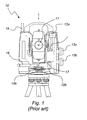
- Figure 1 shows a partially cut-out picture of a prior art total station 10.
- the total station is provided with usual devices and sub-components, such as a center unit 11 for performing distance measurements, servo motors 12a, 12b for aiming the instrument, manual knobs 13a, 13b for manual aiming of the instrument, means 14a, 14b for determining vertical and horizontal rotation angles of the instrument, an antenna 15 for radio communication, etc.
- the total station has an optical plummet 16, comprising an eyepiece extending from the housing and into a position at the center axis of the total station.
- deflecting means such as a mirror or a prism 17, which provides for a view downwards along the vertical rotational axis of the instrument.
- This optical plummet is during use of the instrument used for assisting positioning of the instrument's vertical rotational axis over a desired ground point. The operator typically looks into the eyepiece and physically positions the total station at the desired location guided by the view provided by the optical plummet.
- the eyepiece In order for this procedure to be effective, at least two tasks must be performed very accurately. Firstly, the eyepiece must be mounted, during assembly of the total station, such that the view provided coincides with the vertical rotational axis of the total station. In particular, the mirror or prism 17 that provides the downwards view must be positioned very accurately at the vertical axis of the instrument. Secondly, the operator must carefully position the total station 10 at the desired location. While manufacturing technology may allow for the eyepiece to be correctly positioned during the assembly of the instrument, it is still a time consuming and costly manufacturing step typically requiring manual fine tuning of the eyepiece position. Further, even when the eyepiece is correctly mounted in the total station, correct positioning of the instrument during use is entirely at the responsibility of the operator, and relies upon his or her skill to be accurate in handling the total station in the field.
- an image capturing device/sensor 22 such as a CCD, a CMOS sensor or the like.
- Such total station 20 is shown in figure 2 .
- the image capturing device need not be centered exactly at the instrument vertical axis. Rather, it suffices that the instrument vertical axis coincides with some portion of the image capturing device, such that the instrument nadir can be captured. As will be described in more detail below, image processing and a method according to the present invention may then be used for determining the instrument nadir.
- the following procedure may advantageously be followed during manufacture for calibrating the position of the image sensor 22 with respect to the instrument vertical rotational axis.
- the positional relationship between the sensor 22 and the moving parts of the instrument 20 will remain substantially constant, and a second calibration is normally not required.
- the instrument is delivered to the end user without being calibrated, and the end user may then follow this procedure at least once for making the calibration.
- the end user may also wish to recalibrate the instrument if, for example, the environmental conditions have changed considerably, or following a system reset or for any other reason.
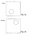
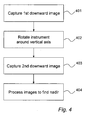
- a first image of the ground below the instrument is captured ( figure 4 , step 401) by the image capturing device 22. As illustrated in figure 3a , this first image is captured at a relative rotational position for the instrument of 0 degrees. As will be understood, this may be any rotational position which has been selected for the first image. Then, the instrument is rotated (step 402) to a new rotational position, in this example 180 degrees relative to the first rotational position, and a second image of the ground below the instrument is captured (step 403) as shown in figure 3b . It should be noted that the instrument has then been rotated about the vertical rotational axis thereof, and the task of determining instrument nadir relative to the captured images will be equivalent to determining the rotational center of the images captured.
- image processing within the instrument is used for calculating the merging distance required in order to make the captured images overlap.
- one of the two captured images in this example is mathematically rotated to correspond to the rotational position of the other image.
- the second image may be mathematically rotated from 180 degrees to 0 degrees, or the first image may be rotated from 0 degrees to 180 degrees. This mathematical rotation of the image is made relative to the image center (or reference) point (x 0 ,y 0 ).
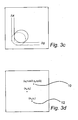
- the images will typically be displaced relative to each other, as illustrated in figure 3c , wherein the broken circle represents the mathematically rotated image.
- Image processing in the instrument determines the merging distance, illustrated in figure 3c as ⁇ x and ⁇ y.
- the eccentricity of the image capturing device i.e. the displacement of the image sensor center (x 0 ,y 0 ) relative to the true instrument center (the vertical rotational axis) is given by half the merging distance.
- the image center center pixel of the image sensor 22
- the vertical rotational axis instrument axis
- instrument nadir is located at (x 0 + ⁇ x/2,y 0 + ⁇ y/2). It will be appreciated that either or both of these coordinates may be negative or positive, depending on the eccentricity of the image capturing device.
- two images are captured at mutual rotational positions of 180 degrees. It will be understood, however, that other rotations are possible and that more than two images may be captured.
- the image processing capabilities of the instrument may be designed to handle suitable selections in this regard.
- the thus calculated instrument nadir may during use be displayed on a screen of the instrument to provide information to the operator.
- the operator has the option to physically position and reposition the instrument until a desired origin of coordinates for a subsequent measurement coincides with the calculated instrument nadir. More preferably, however, the operator is given the option to indicate the desired origin of coordinates on the screen of the instrument (or the origin may be identified automatically by image processing and subsequently verified by the operator). This may be accomplished, for example, by the use of a touch screen or by allowing an indicator or cursor to be moved across the screen. The operator may then indicate the desired origin of coordinates to be (x 1 ,y 1 ), as illustrated in figure 3d .
- Software in the instrument may then provide for the mathematical displacement from the instrument nadir at (x 0 + ⁇ x/2,y 0 + ⁇ y/2) to the desired origin of coordinates at (x 1 ,y 1 ), such that the subsequent measurements performed with the instrument are related to the desired origin at (x 1 ,y 1 ).
- the origin may be indicated by a larger marker, such as a circle, where the "true" origin is located at the center of mass of the marker.
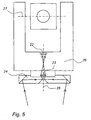
- Embodiments of the present invention may also be designed and structured such that the instrument height above the ground can be determined using the image capturing device, as will now be described with reference to figures 5 and 6 .
- Figure 5 shows schematically a surveying instrument 20 according to the present invention, having the capability of determining the instrument height above the ground below the instrument.
- means such as reflecting prisms 24 (as will be described below) for providing a stereoscopic view of the ground below the instrument.
- prisms or similar means
- the instrument comprises an image capturing device 22 (such as a CCD or a CMOS sensor, as described above), which may be used for capturing an image or a video feed of the ground below the instrument.
- a lens 23 is provided for forming an image of the ground onto the image sensor 22.
- the distance between the lens 23 and the image sensor 22 is preferably substantially equal to the focal length f of the lens 23.
- the image capturing device and the lens are generally positioned on the vertical rotational axis 25 of the instrument; however, accurate positioning of these elements on the vertical rotational axis is not required, since calibration as described above is preferably performed in order to determine image center with respect to instrument center, i.e. center pixel of sensor 22 with respect to the vertical rotation axis 25.
- Reflecting elements in the form of a pair of rhomboid prisms 24 are mounted adjacent the lens, in order to provide a displacement of the image rays from the ground below the instrument.
- the displacement is a parallel displacement (thus not affecting the angle of incidence towards the lens).
- the alidade 26 of the instrument is controlled to rotate about the vertical rotation axis 25 in order to point the instrument in a desired horizontal direction.
- the center unit may also be controlled to rotate about a horizontal rotation axis 27 in order to point the instrument in a desired vertical direction.
- the prisms 24 effecting the parallel displacement of the rays towards the sensor 22 need not rotate with the alidade 26, but may be fixed under the instrument.
- Figure 6 may be useful for understanding how the instrument height may be determined. It should be noted that figure 6 is not drawn to scale, but angles and dimensions are exaggerated for illustrative purposes.
- the image capturing device 22 has a certain field of view on the ground below the instrument (the size of which depends on the optical system).
- the two rhomboid prisms 24 effect a parallel displacement of a respective image within the field of view towards the instrument vertical axis 25 by total internal reflection at the outer edges thereof. After passage through the prisms, the respective image is again reflected by total internal reflection towards the lens 23.
- the rhomboid prisms 24 cause a parallel displacement of the respective images, such that they both enter the lens and are focused towards the image sensor. As illustrated, a single feature within the field of view will cause two separate indications on the image sensor, separated by a distance s .
- means 28 for capturing one of the images at the time For example, there may be provided color filters, which allow the sensor to read out one image separate from the other, where one image may be captured in the green and the other image in the red. Alternatively, mechanical, electromechanical or electronic shutters or the like may be provided, such that only one of the two displaced images at the time reaches the image sensor.
- the height of the prisms above the ground is designated by h . This is the height that is to be determined. Once the height h has been determined, it is a straightforward task to find the height of any other portion of the instrument by adding or subtracting appropriate structural dimensions of the instrument, as will be understood. Under the assumption that the prisms, the lens and the image capturing device are all firmly mounted in the instrument, the height h can be related to the displacement s between the images formed on the image sensor.
- nadir point i.e. at a point where the extension of the vertical axis 25 of the instrument intersects the ground.
- the accuracy in the height determination is a few millimeters or better, depending on the resolution of the image capturing device.
- h 1.5 m
- x 0.04 m
- f 0.04 m
- ⁇ s 1.0 ⁇ m
- the accuracy in the height measurement according to this principle becomes
- the accuracy will be within about 1 mm or better.
- a geodetic instrument wherein an image sensor is used for locating the instrument above a desired point on the ground.
- the positioning of the image sensor with respect to the instrument vertical rotation axis is determined, or calibrated, using a method where two images are captured at different horizontal rotational positions for the instrument, and where the center pixel of the image sensor is related to the vertical rotation axis by means of image processing. It is also disclosed how reflecting elements, such as prisms, may be used for providing stereoscopic vision that can be used for determining the instrument height above the ground.
Description
- The inventive concept disclosed herein relates generally to the positioning of geodetic instruments. More particularly, the inventive concept relates to the determination of position and height over the ground for an instrument by means of an image capturing device.
- Traditionally, optical surveying instruments or geodetic instruments, such as tachymeters or total stations, include sighting means or optical plummets centered on the instrument vertical axis for positioning the instrument over a geodetically fixed reference point. For assisting the centering of the instrument, an optical mark is sometimes used, which is co-aligned with the optical plummet and used for aligning the instrument and the reference point.
- In order for the positioning of the instrument to be accurate, the sighting axis of the optical plummet must be accurately aligned with the instrument vertical rotation axis. Consequently, the assembly of the instrument during manufacture requires a time consuming step of mounting the elements for the optical plummet, and calibration for each individual instrument is typically required in order to ensure that the sighting axis of the optical plummet is properly co-aligned with the instrument vertical rotational axis.
- Once the instrument has been carefully assembled and calibrated, it is the task of the operator to position the instrument over the geodetically fixed point during use. Such careful positioning of the instrument is also time consuming, and relies entirely upon the operator to make the positioning accurate.
-
US-A-6,044,567 discloses a geodetic device in which a position-sensitive photoreceiver or a CCD matrix comprising CCD elements is used for providing control signals to motor-operated drives for positioning a vertical axis of the device over a ground point. - Published US patent application
US 2006/0021236 discloses a surveying instrument including, inter alia, an image pickup means for picking up an area located under a vertical shaft of an instrument body; and a decentering-amount calculation means for calculating an amount of decentering of a survey point with respect to an instrument center. -
EP 0 971 207 A1 discloses a geodetic instrument comprising a CCD line sensor capable of receiving a line image of a patterned target placed on the ground below the instrument, and means for displacing the CCD line sensor by effecting a rotation such that a different line image impinges upon said sensor before and after the displacement. The first and second signals of the CCD line sensor corresponding to the first and second line images of the target are processed to calculate instrument nadir and height of the instrument relative to the ground. - >
- It is an object to provide a geodetic instrument for which both assembly during manufacture and positioning during use are simplified.
- More particularly, it is proposed to include in the geodetic instrument a camera or similar device, capable of capturing an image of the ground below the instrument. The image capturing device may be a CCD, a CMOS sensor or the like. The image captured by the camera may be displayed on a screen for indicating to the operator which portion of the ground is seen by the camera, together with a cross hair, a dot or similar for indicating the instrument nadir.
- By relating a desired origin of coordinates to the captured image(s), and by relating the instrument nadir or center point to the captured image(s), any displacement between the desired origin of coordinates and the instrument nadir may be accounted for without physically moving the instrument. It suffices that the desired origin of coordinates is within the field of view of the image capturing device and that the instrument height above the ground is known.
- As used herein, "instrument nadir" is the downwards direction of the instrument's vertical rotational axis.
- The desired origin of coordinates may be indicated, for example, by means of a recognized pattern on the ground under the instrument, or by an operator manually indicating the desired origin on a screen or the like showing the captured image.
- In the prior art, it has been a time consuming procedure during manufacture of geodetic instruments to accurately position plummet means in alignment with the vertical rotational axis of the instrument. According to the inventive concept disclosed herein, the plummet means comprises an image capturing device or image sensor, such as a camera of suitable type. As will be described in more detail below, it is sufficient if the image capturing device is positioned such that the downwards view along the vertical rotational axis of the instrument falls within the field of view of the image capturing device, thus alleviating the need for extremely accurate mounting.
- Typically, when the instrument is assembled, the center point of the image capturing device (center pixel of the image sensor) will generally not coincide with the vertical rotational axis of the instrument. Advantageously, however, a procedure disclosed herein may be followed for relating the image captured by the camera to the vertical rotational axis of the instrument. This procedure may be seen as one example of a method for calibrating the image capturing device with respect to the instrument vertical rotational axis.
- To this end, there is provided a method in a geodetic instrument having an image sensor for capturing an image of the ground below the instrument, comprising the steps of:
- capturing a first image using said image sensor;
- rotating the instrument around its vertical axis to a new rotational position;
- capturing a second image using said image sensor; and
- processing the captured images to correlate a nadir point for the instrument vertical rotation axis in relation to the image capturing device.
- In order to determine any displacement between the center point of the image capturing device and the instrument vertical rotational axis (or the instrument nadir), the following procedure may be employed. A first image is captured by the camera. The instrument is then rotated, e.g. 180 degrees (200 gon), about its vertical axis to a new rotational position. Then, a second image is captured by the camera. By means of image processing capabilities within the instrument (or possibly remote from the instrument), the first and second images are then processed in order to find the instrument nadir (the vertical rotational axis) with respect to the captured images. As will be understood and as will be explained in more detail below, any displacement of the center point for the image capturing device with respect to the instrument nadir or vertical rotational axis can be found by calculating the merging distance required in order to make the two captured images overlap, wherein the instrument nadir will correspond to half the merging distance in the captured images. In this manner, it is possible to identify which point (e.g. pixel) on the image sensor that corresponds to the instrument nadir. On the instrument screen, a cross hair, a dot or similar may then be displayed at the calculated instrument nadir if desired.
- Once the instrument nadir has been correctly related to the images captured by the camera, the nadir point over which the instrument rotates during use may be indicated on a screen, to aid an operator during placement of the instrument.
- For example, the operator may in the image shown on the instrument screen indicate a desired origin of coordinates for measurement to be made using the instrument. Any difference between the desired origin of coordinates and the determined instrument center point or nadir may then be accounted for by a mathematical displacement of the instrument coordinate system, without any need for further physical repositioning of the instrument. This may prove to be an important advantage for the operator, minimizing the time required for accurately positioning the instrument over a predetermined ground mark. As long as the desired origin of coordinates is within the field of view of the image capturing device (the camera), a mathematical displacement may provide for the offset.
- Hence, in an instrument according to the principles described herein, there is provided an image capturing device, such as a CCD or a CMOS sensor, for capturing an image along the downwards vertical rotational axis of the instrument. A lens is typically provided in front of the image capturing device, as will be understood. The image capturing device is suitably arranged in fixed relation to the instrument alidade, such that the captured image will be rotated together with the instrument alidade.
- The instrument further typically comprises means for storing image processing software and processing means, effective to perform image processing of the captured images. Generally, the image processing may be performed by software, hardware, firmware or any other suitable means for analyzing and processing digital images.
- Preferably, the instrument is further provided with a screen, upon which the captured images may be shown. The screen may also be used for displaying a cross hair or a dot, representing the instrument center line (instrument nadir) with respect to the captured image.
- In addition, an operator may be provided means for indicating a point, such as a desired origin of coordinates in the displayed image. To this end, the screen may be a touch screen, or means may be provided for moving a cursor over the displayed image.
- The general inventive concepts disclosed herein may also be utilized for determining the instrument height over the ground.
- More particularly, there is provided a method for determining a height above ground for a geodetic instrument comprising an image sensor, lens means for forming an image on said image sensor, and means for effecting a parallel displacement of a ray impinging upon said image sensor, comprising the steps of:
- capturing a first image of the ground using a parallel displacement of the ray;
- capturing a second image of the ground;
- determining a separation between the first and the second image on the image sensor; and
- calculating the height based on the amount of parallel displacement, said separation, and the focal length of said lens means.
- To this end, embodiments of the present invention may comprise reflecting elements, such as prisms or the like, which are displaced from the instrument vertical axis and which have the purpose of directing images of the ground under the instrument towards the image capturing device. By having the reflecting elements providing an image of the ground under the instrument at a non-normal angle of incidence, by effecting parallel displacement of image rays, the corresponding reading on the image sensor will be displaced from the center. Using, for example, two such reflecting elements will provide two readings on the image capturing device. By analyzing the displacement between two such readings, and provided that the displacement of the reflecting elements from the instrument vertical axis is known, it becomes possible to calculate the height of the instrument above the ground below. Preferably, the reflecting elements are designed such that they provide a parallel displacement of the field of view into the image capturing device. The larger such parallel displacement is, the larger will the separation be between the readings on the image capturing device. Hence, by determining the separation between the two readings on the image capturing device and knowing the displacement of the reflecting elements, the instrument height can be calculated. This will be described in more detail in the description below.
- As will be understood, the methods disclosed herein are preferably performed by using computer software incorporated into the geodetic instrument. Thus, the present invention also relates to computer software for performing the methods.
- In the detailed description that follows, reference is made to the accompanying drawings, on which:
-
Fig. 1 illustrates a prior art total station which is provided with a conventional optical plummet. -
Fig. 2 illustrates a total station according to the present invention, wherein an image sensor is employed instead of the conventional optical plummet. -
Fig. 3a-d are schematic pictures illustrating how images are captured and processed according to the present invention. -
Fig. 4 is a flow chart illustrating the main steps of a method according to this invention. -
Fig. 5 shows schematically some parts of an instrument according to the present invention, having height measuring capabilities. -
Fig. 6 illustrates schematically how the instrument height can be determined in the instrument schematically illustrated infigure 5 . - Although the figures may illustrate currently preferred embodiments, it is to be understood that they represent illustrative examples without any intention to limit the claimed scope.
-
Figure 1 shows a partially cut-out picture of a priorart total station 10. The total station is provided with usual devices and sub-components, such as acenter unit 11 for performing distance measurements,servo motors manual knobs optical plummet 16, comprising an eyepiece extending from the housing and into a position at the center axis of the total station. At the point where the sight line of the eyepiece coincides with the vertical rotational axis of the total station, there is provided deflecting means, such as a mirror or aprism 17, which provides for a view downwards along the vertical rotational axis of the instrument. This optical plummet is during use of the instrument used for assisting positioning of the instrument's vertical rotational axis over a desired ground point. The operator typically looks into the eyepiece and physically positions the total station at the desired location guided by the view provided by the optical plummet. - In order for this procedure to be effective, at least two tasks must be performed very accurately. Firstly, the eyepiece must be mounted, during assembly of the total station, such that the view provided coincides with the vertical rotational axis of the total station. In particular, the mirror or
prism 17 that provides the downwards view must be positioned very accurately at the vertical axis of the instrument. Secondly, the operator must carefully position thetotal station 10 at the desired location. While manufacturing technology may allow for the eyepiece to be correctly positioned during the assembly of the instrument, it is still a time consuming and costly manufacturing step typically requiring manual fine tuning of the eyepiece position. Further, even when the eyepiece is correctly mounted in the total station, correct positioning of the instrument during use is entirely at the responsibility of the operator, and relies upon his or her skill to be accurate in handling the total station in the field. - According to the inventive concept described and claimed herein, it is proposed to replace the prior art
optical plummet 16 and eyepiece with an image capturing device/sensor 22, such as a CCD, a CMOS sensor or the like. Suchtotal station 20 is shown infigure 2 . The image capturing device need not be centered exactly at the instrument vertical axis. Rather, it suffices that the instrument vertical axis coincides with some portion of the image capturing device, such that the instrument nadir can be captured. As will be described in more detail below, image processing and a method according to the present invention may then be used for determining the instrument nadir. - To illustrate how the image capturing device may be used for determining instrument nadir and for relating measurements made by the instrument to a desired coordinate system (origin of coordinates), reference is made to
figure 3a-d andfigure 4 of the drawings. - For the procedure described below, it will be assumed that the
instrument 20 is already appropriately level, and that the desired origin of coordinates is located within the field of view of theimage sensor 22. - The following procedure may advantageously be followed during manufacture for calibrating the position of the
image sensor 22 with respect to the instrument vertical rotational axis. Within reasonable environmental conditions, the positional relationship between thesensor 22 and the moving parts of theinstrument 20 will remain substantially constant, and a second calibration is normally not required. It is, however, also conceivable that the instrument is delivered to the end user without being calibrated, and the end user may then follow this procedure at least once for making the calibration. The end user may also wish to recalibrate the instrument if, for example, the environmental conditions have changed considerably, or following a system reset or for any other reason. - A first image of the ground below the instrument is captured (
figure 4 , step 401) by theimage capturing device 22. As illustrated infigure 3a , this first image is captured at a relative rotational position for the instrument of 0 degrees. As will be understood, this may be any rotational position which has been selected for the first image. Then, the instrument is rotated (step 402) to a new rotational position, in this example 180 degrees relative to the first rotational position, and a second image of the ground below the instrument is captured (step 403) as shown infigure 3b . It should be noted that the instrument has then been rotated about the vertical rotational axis thereof, and the task of determining instrument nadir relative to the captured images will be equivalent to determining the rotational center of the images captured. - For clarity, the image captured by the camera is represented by a simple circle in
figures 3a and 3b . It will be appreciated, however, that an actual image captured during calibration of the inventive instrument will have more complex features. The basic principle of relating instrument nadir to the image capturing device, however, remains the same. - To find the instrument nadir relative to the captured images (i.e. to determine the eccentricity of the
image capturing device 22 relative to the instrument vertical rotational axis), image processing within the instrument (or possibly remote from the instrument) is used for calculating the merging distance required in order to make the captured images overlap. To find the merging distance, one of the two captured images in this example is mathematically rotated to correspond to the rotational position of the other image. In other words, the second image may be mathematically rotated from 180 degrees to 0 degrees, or the first image may be rotated from 0 degrees to 180 degrees. This mathematical rotation of the image is made relative to the image center (or reference) point (x0,y0). After such mathematical rotation, the images will typically be displaced relative to each other, as illustrated infigure 3c , wherein the broken circle represents the mathematically rotated image. Image processing in the instrument then determines the merging distance, illustrated infigure 3c as Δx and Δy. Now, the eccentricity of the image capturing device, i.e. the displacement of the image sensor center (x0,y0) relative to the true instrument center (the vertical rotational axis), is given by half the merging distance. Thus, if the image center (center pixel of the image sensor 22) is located at coordinates (x0,y0), then the vertical rotational axis (instrument nadir) is located at (x0+Δx/2,y0+Δy/2). It will be appreciated that either or both of these coordinates may be negative or positive, depending on the eccentricity of the image capturing device. - In the example above, two images are captured at mutual rotational positions of 180 degrees. It will be understood, however, that other rotations are possible and that more than two images may be captured. The image processing capabilities of the instrument may be designed to handle suitable selections in this regard.
- Once the instrument has been thus calibrated, there should normally not be any need for recalibration. However, the procedure for calibrating the instrument in this respect is comparatively simple, and the end user may decide to perform recalibration at any time.
- Advantageously, the thus calculated instrument nadir may during use be displayed on a screen of the instrument to provide information to the operator.
- During use, the operator has the option to physically position and reposition the instrument until a desired origin of coordinates for a subsequent measurement coincides with the calculated instrument nadir. More preferably, however, the operator is given the option to indicate the desired origin of coordinates on the screen of the instrument (or the origin may be identified automatically by image processing and subsequently verified by the operator). This may be accomplished, for example, by the use of a touch screen or by allowing an indicator or cursor to be moved across the screen. The operator may then indicate the desired origin of coordinates to be (x1,y1), as illustrated in
figure 3d . Software in the instrument may then provide for the mathematical displacement from the instrument nadir at (x0+Δx/2,y0+Δy/2) to the desired origin of coordinates at (x1,y1), such that the subsequent measurements performed with the instrument are related to the desired origin at (x1,y1). In cases where the resolution of the screen is limited, the origin may be indicated by a larger marker, such as a circle, where the "true" origin is located at the center of mass of the marker. - Embodiments of the present invention may also be designed and structured such that the instrument height above the ground can be determined using the image capturing device, as will now be described with reference to
figures 5 and6 . -
Figure 5 shows schematically a surveyinginstrument 20 according to the present invention, having the capability of determining the instrument height above the ground below the instrument. To this end, there is provided means, such as reflecting prisms 24 (as will be described below) for providing a stereoscopic view of the ground below the instrument. Such prisms (or similar means) are preferably removably attached to theinstrument 20 when a height measurement is to be made. The instrument comprises an image capturing device 22 (such as a CCD or a CMOS sensor, as described above), which may be used for capturing an image or a video feed of the ground below the instrument. Alens 23 is provided for forming an image of the ground onto theimage sensor 22. The distance between thelens 23 and theimage sensor 22 is preferably substantially equal to the focal length f of thelens 23. The image capturing device and the lens are generally positioned on the verticalrotational axis 25 of the instrument; however, accurate positioning of these elements on the vertical rotational axis is not required, since calibration as described above is preferably performed in order to determine image center with respect to instrument center, i.e. center pixel ofsensor 22 with respect to thevertical rotation axis 25. Reflecting elements in the form of a pair ofrhomboid prisms 24 are mounted adjacent the lens, in order to provide a displacement of the image rays from the ground below the instrument. Preferably, the displacement is a parallel displacement (thus not affecting the angle of incidence towards the lens). Due to the rhomboid prisms, and the ensuing displacement of the field of view, a single physical feature on the ground below the instrument will cause two displaced images on theimage sensor 22. Since the displacement of the image caused by the prisms is known, the instrument height above the ground may be determined from the displacement obtained on the image sensor. - As indicated in
figure 5 , thealidade 26 of the instrument is controlled to rotate about thevertical rotation axis 25 in order to point the instrument in a desired horizontal direction. As for most total stations, the center unit may also be controlled to rotate about ahorizontal rotation axis 27 in order to point the instrument in a desired vertical direction. For the height measurement, theprisms 24 effecting the parallel displacement of the rays towards thesensor 22 need not rotate with thealidade 26, but may be fixed under the instrument. -
Figure 6 may be useful for understanding how the instrument height may be determined. It should be noted thatfigure 6 is not drawn to scale, but angles and dimensions are exaggerated for illustrative purposes. As mentioned above, theimage capturing device 22 has a certain field of view on the ground below the instrument (the size of which depends on the optical system). The tworhomboid prisms 24 effect a parallel displacement of a respective image within the field of view towards the instrumentvertical axis 25 by total internal reflection at the outer edges thereof. After passage through the prisms, the respective image is again reflected by total internal reflection towards thelens 23. In effect, therhomboid prisms 24 cause a parallel displacement of the respective images, such that they both enter the lens and are focused towards the image sensor. As illustrated, a single feature within the field of view will cause two separate indications on the image sensor, separated by a distance s. - In order to separate the two images caused by the prisms on the image sensor, there are provided means 28 for capturing one of the images at the time. For example, there may be provided color filters, which allow the sensor to read out one image separate from the other, where one image may be captured in the green and the other image in the red. Alternatively, mechanical, electromechanical or electronic shutters or the like may be provided, such that only one of the two displaced images at the time reaches the image sensor.
- In
figure 6 , the height of the prisms above the ground is designated by h. This is the height that is to be determined. Once the height h has been determined, it is a straightforward task to find the height of any other portion of the instrument by adding or subtracting appropriate structural dimensions of the instrument, as will be understood. Under the assumption that the prisms, the lens and the image capturing device are all firmly mounted in the instrument, the height h can be related to the displacement s between the images formed on the image sensor. Consider now a feature appearing at the instrument nadir point, i.e. at a point where the extension of thevertical axis 25 of the instrument intersects the ground. Under the assumption that theimage sensor 22 is located at a distance from thelens 23 equal to the focal length f of the lens, geometrical and/or optical considerations now give that the instrument height h is given by h = (xf)/s, where x is the parallel displacement introduced by the reflecting prisms at height h, f is the focal length of the lens, and s is the image separation on the image sensor caused by the parallel displacement. - For typical instrument heights of 1-2 m, it can be shown that the accuracy in the height determination is a few millimeters or better, depending on the resolution of the image capturing device. In order to estimate the accuracy in the height measurement, the relation sh = xf according to above can be differentiated to (s+Δs)(h+Δh) = xf, or (by substituting xf/s = h)

Assuming now that h=1.5 m, x=0.04 m, f=0.04 m, and Δs=1.0 µm, the accuracy in the height measurement according to this principle becomes |Δh| < 0.001 m. Hence, for typical numbers, the accuracy will be within about 1 mm or better. - Although the height measurement principle described above utilizes two reflecting prisms for the displacement of the rays, it is to be understood that one ray may propagate without displacement and that displacement of only one ray may be sufficient. It should also be noted that various other elements may be used instead of reflecting prisms for this purpose.
- In the foregoing description, details about the inventive features have been described and exemplified. It should be understood that an instrument or a method according to this invention will take advantage of various additional functions. Once the present specification has been read and understood, the skilled person will understand how an instrument according to the present invention as defined in the claims can be made and used using various previously known and new features and sub-components.
- A geodetic instrument is disclosed, wherein an image sensor is used for locating the instrument above a desired point on the ground. The positioning of the image sensor with respect to the instrument vertical rotation axis is determined, or calibrated, using a method where two images are captured at different horizontal rotational positions for the instrument, and where the center pixel of the image sensor is related to the vertical rotation axis by means of image processing. It is also disclosed how reflecting elements, such as prisms, may be used for providing stereoscopic vision that can be used for determining the instrument height above the ground.
Claims (17)
- A method of operating a geodetic instrument (20) having an image sensor (22) for capturing an image of the ground below the instrument, comprising the steps of:capturing a first image (401) using said image sensor;rotating the instrument around its vertical axis (402) to a new rotational position;capturing a second image (403) using said image sensor; andprocessing the captured images (404) to correlate a nadir point for the instrument vertical rotation axis in relation to the image sensor.
- The method of claim 1, wherein the first and second images are captured at rotational positions substantially 180 degrees from each other.
- The method of claim 1 or 2, further comprising the step of displaying an image of the ground below the instrument on a screen of the instrument, and indicating the nadir point in said image on the screen.
- The method of any one of the claims 1-3, further comprising the step of acquiring a desired origin of coordinates and relating the desired origin of coordinates to the instrument nadir point, wherein this relation of the origin to the instrument nadir point is used in subsequent geodetic measurements performed by the instrument to relate instrument measurements to the desired origin of coordinates.
- The method of claim 4, wherein the desired origin of coordinates is acquired from an indication made in one of the captured images.
- A method for determining a height above ground for a geodetic instrument comprising an image sensor (22), lens means (23) for forming an image on said image sensor, and means (24) for effecting a parallel displacement of a ray impinging upon said image sensor, comprising the steps of:capturing a first image of the ground using a parallel displacement of the ray;capturing a second image of the ground;determining a separation between the first and the second image on the image sensor; andcalculating the height based on the amount of parallel displacement, said separation, and the focal length of said lens means.
- The method of claim 6, wherein the second image is captured using a parallel displacement of equal magnitude to that used for capturing the first image, but in a different direction.
- A geodetic instrument (20), comprising:a base;an alidade rotatably mounted on the base;an image sensor (22) structured and arranged to capture an image, wherein the image sensor is positioned in fixed relation to said alidade and directed to capture an image of the ground below the instrument; andan image processor adapted to process at least two images captured at different rotational angles of the alidade to relate instrument nadir to the image sensor.
- The instrument of claim 8, further comprising an input device for receiving an origin of coordinates related to the captured image, and means for determining the displacement between said instrument nadir and said origin of coordinates.
- A geodetic instrument comprising an image sensor (22), lens means (23) for forming an image on said image sensor, and means (24) for effecting a parallel displacement of a ray impinging upon said image sensor, and further comprising
means (28) for providing, on the image sensor, a first image of the ground below the instrument using a parallel displacement of the ray;
means (28) for providing, on the image sensor, a second image of the ground below the instrument;
means for determining a separation between the first and the second image provided on the image sensor; and
means for calculating the instrument height (h) above the ground based on the amount of parallel displacement (s), said separation, and the focal length (f) of said lens means. - The instrument of claim 10, wherein the means for providing the second image (28) uses a parallel displacement of equal magnitude to that used for capturing the first image, but in a different direction.
- The instrument of claim 10 or 11, wherein the distance between the lens means and the image sensor is substantially equal to the focal length (f) of said lens means.
- The instrument of any one of claims 10-12, comprising a reflecting prism (24) for effecting said parallel displacement.
- The instrument of any one of claims 10-13, further comprising at least one filter for separating said first and second images.
- The instrument of any one of claims 10-13, further comprising at least one shutter for separating said first and second images.
- Computer software stored on a computer readable medium, said software containing instructions for a processor in a geodetic instrument to perform the method according to any one of claims 1 to 5 when executed.
- Computer software stored on a computer readable medium, said software containing instructions for a processsor in a geodetic instrument to perform the method according to any one of claims 6 to 7 when executed.
Applications Claiming Priority (1)
| Application Number | Priority Date | Filing Date | Title |
|---|---|---|---|
| PCT/EP2006/012535 WO2008077432A1 (en) | 2006-12-27 | 2006-12-27 | Geodetic instrument and related method |
Publications (2)
| Publication Number | Publication Date |
|---|---|
| EP2097716A1 EP2097716A1 (en) | 2009-09-09 |
| EP2097716B1 true EP2097716B1 (en) | 2013-07-31 |
Family
ID=38255852
Family Applications (1)
| Application Number | Title | Priority Date | Filing Date |
|---|---|---|---|
| EP06829874.4A Active EP2097716B1 (en) | 2006-12-27 | 2006-12-27 | Geodetic instrument and related method |
Country Status (4)
| Country | Link |
|---|---|
| US (1) | US7908752B2 (en) |
| EP (1) | EP2097716B1 (en) |
| CN (1) | CN101568800B (en) |
| WO (1) | WO2008077432A1 (en) |
Families Citing this family (11)
| Publication number | Priority date | Publication date | Assignee | Title |
|---|---|---|---|---|
| CN101583841B (en) * | 2007-01-25 | 2011-02-16 | 特林布尔公司 | Aiming of a geodetic instrument |
| US8897482B2 (en) * | 2008-02-29 | 2014-11-25 | Trimble Ab | Stereo photogrammetry from a single station using a surveying instrument with an eccentric camera |
| CN101970985B (en) | 2008-02-29 | 2013-06-12 | 特林布尔公司 | Determining coordinates of a target in relation to a survey instrument having at least two cameras |
| US8659752B2 (en) | 2010-10-25 | 2014-02-25 | Faro Technologies, Inc. | Automated warm-up and stability check for laser trackers |
| CN102261905B (en) * | 2011-04-25 | 2012-11-07 | 西安北方光电有限公司 | Method for adjusting center and focal plane of CCD (charge-coupled device) based on optical telescope imaging system |
| US10531187B2 (en) * | 2016-12-21 | 2020-01-07 | Nortek Security & Control Llc | Systems and methods for audio detection using audio beams |
| EP3640590B1 (en) | 2018-10-17 | 2021-12-01 | Trimble Jena GmbH | Surveying apparatus for surveying an object |
| EP3640677B1 (en) | 2018-10-17 | 2023-08-02 | Trimble Jena GmbH | Tracker of a surveying apparatus for tracking a target |
| EP3696498A1 (en) | 2019-02-15 | 2020-08-19 | Trimble Jena GmbH | Surveying instrument and method of calibrating a survey instrument |
| USD937105S1 (en) * | 2019-03-21 | 2021-11-30 | Trimble Jena Gmbh | Geodetic apparatus |
| US11257234B2 (en) * | 2019-05-24 | 2022-02-22 | Nanjing Polagis Technology Co. Ltd | Method for three-dimensional measurement and calculation of the geographic position and height of a target object based on street view images |
Family Cites Families (9)
| Publication number | Priority date | Publication date | Assignee | Title |
|---|---|---|---|---|
| CN2300883Y (en) * | 1997-03-28 | 1998-12-16 | 李兵 | Aligner of all-station instrument capable of recording and indicating target image |
| DE19716304C1 (en) * | 1997-04-18 | 1998-05-20 | Zeiss Carl Jena Gmbh | Geodetic device for plumbline, theodolite or tachymeter |
| JP3965593B2 (en) * | 1998-07-08 | 2007-08-29 | 株式会社トプコン | Surveying device centripetal position measuring device and surveying instrument |
| DE19941638C1 (en) * | 1999-08-27 | 2000-12-14 | Zeiss Carl Jena Gmbh | Geodatic theodolite or tachometer has laser device used for determining height above ground of common intersection point of telescope optical axis, pivot axis and rotation axis |
| EP1515152A1 (en) * | 2003-09-12 | 2005-03-16 | Leica Geosystems AG | Process for the determination of the direction of an object to be measured |
| JP4424665B2 (en) | 2004-07-30 | 2010-03-03 | 株式会社 ソキア・トプコン | Surveying instrument |
| WO2008043436A1 (en) * | 2006-10-06 | 2008-04-17 | Leica Geosystems Ag | Target object used for retroflexion of optical radiation |
| EP1990607A1 (en) * | 2007-05-10 | 2008-11-12 | Leica Geosystems AG | Method of position determination for a geodetic surveying apparatus |
| US7841094B2 (en) * | 2009-01-27 | 2010-11-30 | Trimble Kaiserslautern Gmbh | Optical instrument with angle indicator and method for operating the same |
-
2006
- 2006-12-27 WO PCT/EP2006/012535 patent/WO2008077432A1/en active Application Filing
- 2006-12-27 US US12/448,604 patent/US7908752B2/en active Active
- 2006-12-27 EP EP06829874.4A patent/EP2097716B1/en active Active
- 2006-12-27 CN CN2006800568047A patent/CN101568800B/en active Active
Also Published As
| Publication number | Publication date |
|---|---|
| US7908752B2 (en) | 2011-03-22 |
| EP2097716A1 (en) | 2009-09-09 |
| CN101568800B (en) | 2011-08-17 |
| WO2008077432A1 (en) | 2008-07-03 |
| US20100037474A1 (en) | 2010-02-18 |
| CN101568800A (en) | 2009-10-28 |
Similar Documents
| Publication | Publication Date | Title |
|---|---|---|
| EP2097716B1 (en) | Geodetic instrument and related method | |
| EP2247921B1 (en) | Determining coordinates of a target in relation to a survey instruments having a camera | |
| US7930835B2 (en) | Aiming of a geodetic instrument | |
| US8629905B2 (en) | Localization of a surveying instrument in relation to a ground mark | |
| EP2141451B1 (en) | Multiple-point measuring method and survey instrument | |
| US9322652B2 (en) | Stereo photogrammetry from a single station using a surveying instrument with an eccentric camera | |
| EP2240740B1 (en) | Localization of a surveying instrument in relation to a ground mark | |
| EP2247922B1 (en) | Determining coordinates of a target in relation to a survey instrument having at least two cameras | |
| EP2047212B1 (en) | Electronic leveling apparatus and method | |
| US20050117024A1 (en) | Gradient displaying method of mobile terminal | |
| US20030160757A1 (en) | Surveying system | |
| US20130113897A1 (en) | Process and arrangement for determining the position of a measuring point in geometrical space | |
| CN110274581B (en) | Total station, method of determining instrument error of total station and machine readable medium | |
| CN112334733A (en) | Calibration device for imaging device, monitoring device, working machine, and calibration method | |
| EP2607846B1 (en) | Surveying apparatus | |
| JPH0914965A (en) | Target for surveying | |
| JP2021039013A (en) | Wall crack measuring machine and measuring method | |
| JP2018013343A (en) | Survey assistance apparatus | |
| EP2240741B1 (en) | Localizing a surveying instrument in relation to a ground mark | |
| US6616347B1 (en) | Camera with rotating optical displacement unit |
Legal Events
| Date | Code | Title | Description |
|---|---|---|---|
| PUAI | Public reference made under article 153(3) epc to a published international application that has entered the european phase |
Free format text: ORIGINAL CODE: 0009012 |
|
| 17P | Request for examination filed |
Effective date: 20090611 |
|
| AK | Designated contracting states |
Kind code of ref document: A1 Designated state(s): AT BE BG CH CY CZ DE DK EE ES FI FR GB GR HU IE IS IT LI LT LU LV MC NL PL PT RO SE SI SK TR |
|
| DAX | Request for extension of the european patent (deleted) | ||
| GRAP | Despatch of communication of intention to grant a patent |
Free format text: ORIGINAL CODE: EPIDOSNIGR1 |
|
| RIN1 | Information on inventor provided before grant (corrected) |
Inventor name: WESTERMARK, MAGNUS Inventor name: SVANHOLM, SET Inventor name: HERTZMAN, MIKAEL |
|
| GRAS | Grant fee paid |
Free format text: ORIGINAL CODE: EPIDOSNIGR3 |
|
| GRAA | (expected) grant |
Free format text: ORIGINAL CODE: 0009210 |
|
| AK | Designated contracting states |
Kind code of ref document: B1 Designated state(s): AT BE BG CH CY CZ DE DK EE ES FI FR GB GR HU IE IS IT LI LT LU LV MC NL PL PT RO SE SI SK TR |
|
| REG | Reference to a national code |
Ref country code: GB Ref legal event code: FG4D Ref country code: CH Ref legal event code: EP |
|
| REG | Reference to a national code |
Ref country code: AT Ref legal event code: REF Ref document number: 624900 Country of ref document: AT Kind code of ref document: T Effective date: 20130815 |
|
| REG | Reference to a national code |
Ref country code: IE Ref legal event code: FG4D |
|
| REG | Reference to a national code |
Ref country code: DE Ref legal event code: R096 Ref document number: 602006037678 Country of ref document: DE Effective date: 20130926 |
|
| REG | Reference to a national code |
Ref country code: AT Ref legal event code: MK05 Ref document number: 624900 Country of ref document: AT Kind code of ref document: T Effective date: 20130731 |
|
| REG | Reference to a national code |
Ref country code: NL Ref legal event code: VDEP Effective date: 20130731 |
|
| REG | Reference to a national code |
Ref country code: LT Ref legal event code: MG4D |
|
| PG25 | Lapsed in a contracting state [announced via postgrant information from national office to epo] |
Ref country code: AT Free format text: LAPSE BECAUSE OF FAILURE TO SUBMIT A TRANSLATION OF THE DESCRIPTION OR TO PAY THE FEE WITHIN THE PRESCRIBED TIME-LIMIT Effective date: 20130731 Ref country code: CY Free format text: LAPSE BECAUSE OF FAILURE TO SUBMIT A TRANSLATION OF THE DESCRIPTION OR TO PAY THE FEE WITHIN THE PRESCRIBED TIME-LIMIT Effective date: 20130807 Ref country code: BE Free format text: LAPSE BECAUSE OF FAILURE TO SUBMIT A TRANSLATION OF THE DESCRIPTION OR TO PAY THE FEE WITHIN THE PRESCRIBED TIME-LIMIT Effective date: 20130731 Ref country code: PT Free format text: LAPSE BECAUSE OF FAILURE TO SUBMIT A TRANSLATION OF THE DESCRIPTION OR TO PAY THE FEE WITHIN THE PRESCRIBED TIME-LIMIT Effective date: 20131202 Ref country code: LT Free format text: LAPSE BECAUSE OF FAILURE TO SUBMIT A TRANSLATION OF THE DESCRIPTION OR TO PAY THE FEE WITHIN THE PRESCRIBED TIME-LIMIT Effective date: 20130731 Ref country code: SE Free format text: LAPSE BECAUSE OF FAILURE TO SUBMIT A TRANSLATION OF THE DESCRIPTION OR TO PAY THE FEE WITHIN THE PRESCRIBED TIME-LIMIT Effective date: 20130731 Ref country code: IS Free format text: LAPSE BECAUSE OF FAILURE TO SUBMIT A TRANSLATION OF THE DESCRIPTION OR TO PAY THE FEE WITHIN THE PRESCRIBED TIME-LIMIT Effective date: 20131130 |
|
| PG25 | Lapsed in a contracting state [announced via postgrant information from national office to epo] |
Ref country code: SI Free format text: LAPSE BECAUSE OF FAILURE TO SUBMIT A TRANSLATION OF THE DESCRIPTION OR TO PAY THE FEE WITHIN THE PRESCRIBED TIME-LIMIT Effective date: 20130731 Ref country code: LV Free format text: LAPSE BECAUSE OF FAILURE TO SUBMIT A TRANSLATION OF THE DESCRIPTION OR TO PAY THE FEE WITHIN THE PRESCRIBED TIME-LIMIT Effective date: 20130731 Ref country code: FI Free format text: LAPSE BECAUSE OF FAILURE TO SUBMIT A TRANSLATION OF THE DESCRIPTION OR TO PAY THE FEE WITHIN THE PRESCRIBED TIME-LIMIT Effective date: 20130731 Ref country code: GR Free format text: LAPSE BECAUSE OF FAILURE TO SUBMIT A TRANSLATION OF THE DESCRIPTION OR TO PAY THE FEE WITHIN THE PRESCRIBED TIME-LIMIT Effective date: 20131101 Ref country code: NL Free format text: LAPSE BECAUSE OF FAILURE TO SUBMIT A TRANSLATION OF THE DESCRIPTION OR TO PAY THE FEE WITHIN THE PRESCRIBED TIME-LIMIT Effective date: 20130731 Ref country code: PL Free format text: LAPSE BECAUSE OF FAILURE TO SUBMIT A TRANSLATION OF THE DESCRIPTION OR TO PAY THE FEE WITHIN THE PRESCRIBED TIME-LIMIT Effective date: 20130731 |
|
| PG25 | Lapsed in a contracting state [announced via postgrant information from national office to epo] |
Ref country code: CY Free format text: LAPSE BECAUSE OF FAILURE TO SUBMIT A TRANSLATION OF THE DESCRIPTION OR TO PAY THE FEE WITHIN THE PRESCRIBED TIME-LIMIT Effective date: 20130731 |
|
| PG25 | Lapsed in a contracting state [announced via postgrant information from national office to epo] |
Ref country code: DK Free format text: LAPSE BECAUSE OF FAILURE TO SUBMIT A TRANSLATION OF THE DESCRIPTION OR TO PAY THE FEE WITHIN THE PRESCRIBED TIME-LIMIT Effective date: 20130731 Ref country code: SK Free format text: LAPSE BECAUSE OF FAILURE TO SUBMIT A TRANSLATION OF THE DESCRIPTION OR TO PAY THE FEE WITHIN THE PRESCRIBED TIME-LIMIT Effective date: 20130731 Ref country code: RO Free format text: LAPSE BECAUSE OF FAILURE TO SUBMIT A TRANSLATION OF THE DESCRIPTION OR TO PAY THE FEE WITHIN THE PRESCRIBED TIME-LIMIT Effective date: 20130731 Ref country code: CZ Free format text: LAPSE BECAUSE OF FAILURE TO SUBMIT A TRANSLATION OF THE DESCRIPTION OR TO PAY THE FEE WITHIN THE PRESCRIBED TIME-LIMIT Effective date: 20130731 Ref country code: EE Free format text: LAPSE BECAUSE OF FAILURE TO SUBMIT A TRANSLATION OF THE DESCRIPTION OR TO PAY THE FEE WITHIN THE PRESCRIBED TIME-LIMIT Effective date: 20130731 |
|
| PG25 | Lapsed in a contracting state [announced via postgrant information from national office to epo] |
Ref country code: IT Free format text: LAPSE BECAUSE OF FAILURE TO SUBMIT A TRANSLATION OF THE DESCRIPTION OR TO PAY THE FEE WITHIN THE PRESCRIBED TIME-LIMIT Effective date: 20130731 Ref country code: ES Free format text: LAPSE BECAUSE OF FAILURE TO SUBMIT A TRANSLATION OF THE DESCRIPTION OR TO PAY THE FEE WITHIN THE PRESCRIBED TIME-LIMIT Effective date: 20130731 |
|
| PLBE | No opposition filed within time limit |
Free format text: ORIGINAL CODE: 0009261 |
|
| STAA | Information on the status of an ep patent application or granted ep patent |
Free format text: STATUS: NO OPPOSITION FILED WITHIN TIME LIMIT |
|
| 26N | No opposition filed |
Effective date: 20140502 |
|
| REG | Reference to a national code |
Ref country code: CH Ref legal event code: PL |
|
| REG | Reference to a national code |
Ref country code: DE Ref legal event code: R097 Ref document number: 602006037678 Country of ref document: DE Effective date: 20140502 |
|
| GBPC | Gb: european patent ceased through non-payment of renewal fee |
Effective date: 20131227 |
|
| PG25 | Lapsed in a contracting state [announced via postgrant information from national office to epo] |
Ref country code: MC Free format text: LAPSE BECAUSE OF FAILURE TO SUBMIT A TRANSLATION OF THE DESCRIPTION OR TO PAY THE FEE WITHIN THE PRESCRIBED TIME-LIMIT Effective date: 20130731 Ref country code: LU Free format text: LAPSE BECAUSE OF FAILURE TO SUBMIT A TRANSLATION OF THE DESCRIPTION OR TO PAY THE FEE WITHIN THE PRESCRIBED TIME-LIMIT Effective date: 20131227 |
|
| REG | Reference to a national code |
Ref country code: IE Ref legal event code: MM4A |
|
| REG | Reference to a national code |
Ref country code: FR Ref legal event code: ST Effective date: 20140829 |
|
| PG25 | Lapsed in a contracting state [announced via postgrant information from national office to epo] |
Ref country code: CH Free format text: LAPSE BECAUSE OF NON-PAYMENT OF DUE FEES Effective date: 20131231 Ref country code: LI Free format text: LAPSE BECAUSE OF NON-PAYMENT OF DUE FEES Effective date: 20131231 Ref country code: IE Free format text: LAPSE BECAUSE OF NON-PAYMENT OF DUE FEES Effective date: 20131227 |
|
| PG25 | Lapsed in a contracting state [announced via postgrant information from national office to epo] |
Ref country code: GB Free format text: LAPSE BECAUSE OF NON-PAYMENT OF DUE FEES Effective date: 20131227 Ref country code: FR Free format text: LAPSE BECAUSE OF NON-PAYMENT OF DUE FEES Effective date: 20131231 |
|
| PG25 | Lapsed in a contracting state [announced via postgrant information from national office to epo] |
Ref country code: TR Free format text: LAPSE BECAUSE OF FAILURE TO SUBMIT A TRANSLATION OF THE DESCRIPTION OR TO PAY THE FEE WITHIN THE PRESCRIBED TIME-LIMIT Effective date: 20130731 |
|
| PG25 | Lapsed in a contracting state [announced via postgrant information from national office to epo] |
Ref country code: BG Free format text: LAPSE BECAUSE OF FAILURE TO SUBMIT A TRANSLATION OF THE DESCRIPTION OR TO PAY THE FEE WITHIN THE PRESCRIBED TIME-LIMIT Effective date: 20130731 Ref country code: HU Free format text: LAPSE BECAUSE OF FAILURE TO SUBMIT A TRANSLATION OF THE DESCRIPTION OR TO PAY THE FEE WITHIN THE PRESCRIBED TIME-LIMIT; INVALID AB INITIO Effective date: 20061227 |
|
| PGFP | Annual fee paid to national office [announced via postgrant information from national office to epo] |
Ref country code: DE Payment date: 20221227 Year of fee payment: 17 |