EP2097660B1 - An operating device for a differential lock in a vehicle - Google Patents
An operating device for a differential lock in a vehicle Download PDFInfo
- Publication number
- EP2097660B1 EP2097660B1 EP07852178.8A EP07852178A EP2097660B1 EP 2097660 B1 EP2097660 B1 EP 2097660B1 EP 07852178 A EP07852178 A EP 07852178A EP 2097660 B1 EP2097660 B1 EP 2097660B1
- Authority
- EP
- European Patent Office
- Prior art keywords
- connecting means
- operating
- operating device
- limbs
- fork
- Prior art date
- Legal status (The legal status is an assumption and is not a legal conclusion. Google has not performed a legal analysis and makes no representation as to the accuracy of the status listed.)
- Active
Links
- 230000000717 retained effect Effects 0.000 claims 1
- 230000009699 differential effect Effects 0.000 description 2
- 230000000694 effects Effects 0.000 description 1
- 238000005242 forging Methods 0.000 description 1
- 238000004519 manufacturing process Methods 0.000 description 1
Images


Classifications
-
- F—MECHANICAL ENGINEERING; LIGHTING; HEATING; WEAPONS; BLASTING
- F16—ENGINEERING ELEMENTS AND UNITS; GENERAL MEASURES FOR PRODUCING AND MAINTAINING EFFECTIVE FUNCTIONING OF MACHINES OR INSTALLATIONS; THERMAL INSULATION IN GENERAL
- F16H—GEARING
- F16H48/00—Differential gearings
- F16H48/20—Arrangements for suppressing or influencing the differential action, e.g. locking devices
- F16H48/30—Arrangements for suppressing or influencing the differential action, e.g. locking devices using externally-actuatable means
-
- F—MECHANICAL ENGINEERING; LIGHTING; HEATING; WEAPONS; BLASTING
- F16—ENGINEERING ELEMENTS AND UNITS; GENERAL MEASURES FOR PRODUCING AND MAINTAINING EFFECTIVE FUNCTIONING OF MACHINES OR INSTALLATIONS; THERMAL INSULATION IN GENERAL
- F16H—GEARING
- F16H48/00—Differential gearings
- F16H48/06—Differential gearings with gears having orbital motion
- F16H48/08—Differential gearings with gears having orbital motion comprising bevel gears
-
- F—MECHANICAL ENGINEERING; LIGHTING; HEATING; WEAPONS; BLASTING
- F16—ENGINEERING ELEMENTS AND UNITS; GENERAL MEASURES FOR PRODUCING AND MAINTAINING EFFECTIVE FUNCTIONING OF MACHINES OR INSTALLATIONS; THERMAL INSULATION IN GENERAL
- F16H—GEARING
- F16H48/00—Differential gearings
- F16H48/20—Arrangements for suppressing or influencing the differential action, e.g. locking devices
- F16H48/24—Arrangements for suppressing or influencing the differential action, e.g. locking devices using positive clutches or brakes
-
- F—MECHANICAL ENGINEERING; LIGHTING; HEATING; WEAPONS; BLASTING
- F16—ENGINEERING ELEMENTS AND UNITS; GENERAL MEASURES FOR PRODUCING AND MAINTAINING EFFECTIVE FUNCTIONING OF MACHINES OR INSTALLATIONS; THERMAL INSULATION IN GENERAL
- F16H—GEARING
- F16H48/00—Differential gearings
- F16H48/20—Arrangements for suppressing or influencing the differential action, e.g. locking devices
- F16H48/30—Arrangements for suppressing or influencing the differential action, e.g. locking devices using externally-actuatable means
- F16H48/34—Arrangements for suppressing or influencing the differential action, e.g. locking devices using externally-actuatable means using electromagnetic or electric actuators
-
- F—MECHANICAL ENGINEERING; LIGHTING; HEATING; WEAPONS; BLASTING
- F16—ENGINEERING ELEMENTS AND UNITS; GENERAL MEASURES FOR PRODUCING AND MAINTAINING EFFECTIVE FUNCTIONING OF MACHINES OR INSTALLATIONS; THERMAL INSULATION IN GENERAL
- F16H—GEARING
- F16H48/00—Differential gearings
- F16H48/20—Arrangements for suppressing or influencing the differential action, e.g. locking devices
- F16H2048/204—Control of arrangements for suppressing differential actions
-
- F—MECHANICAL ENGINEERING; LIGHTING; HEATING; WEAPONS; BLASTING
- F16—ENGINEERING ELEMENTS AND UNITS; GENERAL MEASURES FOR PRODUCING AND MAINTAINING EFFECTIVE FUNCTIONING OF MACHINES OR INSTALLATIONS; THERMAL INSULATION IN GENERAL
- F16H—GEARING
- F16H2200/00—Transmissions for multiple ratios
- F16H2200/20—Transmissions using gears with orbital motion
- F16H2200/203—Transmissions using gears with orbital motion characterised by the engaging friction means not of the freewheel type, e.g. friction clutches or brakes
- F16H2200/2071—Transmissions using gears with orbital motion characterised by the engaging friction means not of the freewheel type, e.g. friction clutches or brakes using three freewheel mechanism
-
- F—MECHANICAL ENGINEERING; LIGHTING; HEATING; WEAPONS; BLASTING
- F16—ENGINEERING ELEMENTS AND UNITS; GENERAL MEASURES FOR PRODUCING AND MAINTAINING EFFECTIVE FUNCTIONING OF MACHINES OR INSTALLATIONS; THERMAL INSULATION IN GENERAL
- F16H—GEARING
- F16H48/00—Differential gearings
- F16H48/20—Arrangements for suppressing or influencing the differential action, e.g. locking devices
- F16H48/30—Arrangements for suppressing or influencing the differential action, e.g. locking devices using externally-actuatable means
- F16H48/32—Arrangements for suppressing or influencing the differential action, e.g. locking devices using externally-actuatable means using fluid pressure actuators
Definitions
- the present invention relates to an operating device for a differential lock in a vehicle according to the preamble of claim 1.
- Vehicles usually have a differential gear between two powered wheels.
- the differential gear makes it possible for the powered wheels to run at different speeds, e.g. when negotiating a bend, while at the same time the differential gear distributes driving power equally to both of the powered wheels.
- On vehicles with more than two powered wheels there may also be a differential gear on each driveshaft between the forward and rear driveshafts.
- the differential effect of a differential gear can be reduced or totally eliminated with a differential lock.
- heavy vehicles e.g.
- the differential gear usually has a differential lock by means of which the powered wheels on a driveshaft, and possibly also a plurality of powered wheels on more than one driveshaft, e.g. in a four-wheel drive system, can be locked relative to one another.
- a differential lock by means of which the powered wheels on a driveshaft, and possibly also a plurality of powered wheels on more than one driveshaft, e.g. in a four-wheel drive system, can be locked relative to one another.
- the differential lock is usually an axial toothed connection in which the engagement movement is effected by means of compressed air and the disengagement movement is usually by means of compressed air or return spring force.
- a differential lock in the form of an axial toothed connection usually comprises a separate connecting means with teeth which engage with/are disengaged from teeth arranged on a differential housing whereby a mechanically firm connection is made/broken in the vehicle's differential gear between powered wheels situated on the same driveshaft but each on their respective side of the vehicle, this being achieved by the driving shafts of these wheels being locked relative to/disconnected from one another in a rotational direction.
- This is effected by the connecting means being movable relative to the driving shaft on one side in its axial direction but fixed in its rotational direction, while at the same time the differential housing is fixed relative to the driving shaft on the other side in its axial direction.
- the separate connecting means is moved into/out of engagement with the differential housing by means of an operating fork which is often a forging.
- a problem with a differential gear with a differential lock as above is that during servicing work which involves removal of the driving shaft on which the separate connecting means is arranged, or during the fitting of this shaft in the course of manufacturing the vehicle, the separate connecting means has to be locked firmly in the operating fork by one or more screws or rivets before said driving shaft is removed/fitted, in order to avoid the separate connecting means being moved out of the operating fork. If the separate connecting means loses contact with the operating fork, this may in the worst case lead to having to remove parts of the gear housing in order to be able to put the connecting means back in a correct position relative to the operating fork.
- US 2,620,055 describes an operating device for a differential lock for a vehicle, which operating device comprises two arc-shaped parts that are screwed and clamped onto the connection means.
- the separate first connecting means has to be locked firmly in the operating fork by one or more screws or rivets before the driving shaft, on which the separate connecting means is arranged, is removed or fitted, in order to prevent the separate connecting means from being moved out of the operating fork.
- the operating device according to claim 1 has the characteristic of the differential lock being engaged by a mechanically firm connection which is effected between the two connecting means such that they are brought into engagement with one another by means of the operating fork.
- Figure 1 depicts schematically a gear housing 2 in a vehicle 1 with a differential gear 4 with two driving shafts 6, 8 and an operating device 10 for a differential lock 12 according to a first embodiment of the invention, in which the differential lock operating device 10 comprises a separate connecting means 14 which is movable relative to one driving shaft 6 in its axial direction but fixed in its rotational direction by a mechanical connection 15, e.g. a splined connection, and a second connecting means 16 which is fixed relative to the second driving shaft 8 in its axial direction.
- a mechanical connection 15 e.g. a splined connection
- the separate connecting means 14 is provided with teeth 18, 20 which are adapted to engaging with/being disengaged from teeth 22, 24 arranged on the second connecting means 16 whereby a mechanical firm connection is made/broken in the differential gear 4 of the vehicle 1 between the powered wheels 26, 28 situated on the same driveshaft 30, which driveshaft 30 comprises two driving shafts 6, 8, each on their respective side of the vehicle, this being achieved by these driving shafts 6, 8 of the powered wheels 26, 28 being locked relative to/disengaged from one another in a rotational direction.
- the separate connecting means 14 is moved into/disengaged from the second connecting means 16 by means of an operating fork 32 whose engagement movement is preferably controlled by a cylinder 34 which is preferably a pneumatic cylinder.
- the disengagement movement of the operating fork 32 may be effected by the cylinder 34 or by spring force (not depicted).
- the second connecting means 16 is preferably the differential housing 16 of the differential gear 4, which housing is supported for rotation by bearings 36, 38 in the gear housing 2 in a conventional manner.
- the drawing also shows the input driveshaft 42 to the gear housing 2 from the engine 40 of the vehicle 1.
- the whole or portions of the aforesaid operating cylinder 34 may be situated outside the gear housing 2.
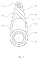
- Figure 2 depicts schematically an operating device 10 for a differential lock 4 according to a first embodiment of the invention and shows the separate connecting means 14 with teeth 18, 20 and internal grooves 44, 46 for fixing the separate connecting means 14 to one driving shaft 6 by mechanical connection.
- the drawing also shows the operating fork 32 and a fastening 48 of the piston 35 of the operating cylinder 34, which fastening is preferably in a recess in the operating fork 32.
- the operating fork 32 is adapted to fitting in a groove 56 of the separate connecting means 14.
- Figure 3 depicts schematically a cross-section of an operating fork 32 and a separate connecting means 14 of an operating device 10 for a differential lock according to a first embodiment of the invention, in which the operating fork 32 comprises a body 50 with a fastening 48, preferably a recess, for a piston 35 of an operating cylinder, and two limbs 52, 54 which are adapted to fitting in a groove 56 of the separate connecting means 14.
- the operating fork 32 comprises a body 50 with a fastening 48, preferably a recess, for a piston 35 of an operating cylinder, and two limbs 52, 54 which are adapted to fitting in a groove 56 of the separate connecting means 14.
- Figure 4 depicts schematically a cross-section of an operating fork 32 and a separate connecting means 14 of an operating device 10 for a differential lock according to Figure 3 , wherein the operating fork 32 comprises a body 50 with a fastening 48, preferably a recess, for a piston 35 of an operating cylinder 34, and two limbs 52, 54 which are adapted to fitting in a groove 56 of the separate connecting means 14, and wherein it may be seen that when the separate connecting means 14 and the operating fork 32 are fitted together the limbs 52, 54 of the operating fork 32 will spring outwards in the respective directions of the arrows A and B when the limbs 52, 54 of the operating fork 32 pass the cross-sectional centre 57 of the connecting means 14.
- Figure 5 depicts schematically a cross-section of a operating fork and a separate connecting means 14 of an operating device 10 for a differential lock according to Figure 2 , wherein the operating fork 32 comprises a body 50 with a fastening 48, preferably a recess, for a piston 35 of an operating cylinder, and two limbs 52, 54 which are adapted to fitting in a groove 56 of the separate connecting means 14, and wherein it may be seen that when the separate connecting means 14 and the operating fork 32 are fitted together so that the limbs 52, 54 of the operating fork 32 pass the cross-sectional centre 57 of the separate connecting means 14 and the limbs 52, 54 of the operating fork 32 will spring back inwards to their original state depicted in Figure 3 .
- the separate connecting means 14 and the operating fork 32 are fitted together so that the limbs 52, 54 of the operating fork 32 pass the cross-sectional centre 57 of the separate connecting means 14 and the limbs 52, 54 of the operating fork 32 will spring back inward
- the operating fork 32 is arranged with radial clearance 59, 61 in the groove 56 of the separate connecting means 14 during operation, in order to prevent unnecessary wear of the operating fork 32 and the separate connecting means 14 respectively when the separate connecting means 14 rotates with the driving shaft 6.
- This can be achieved with, for example, a guide or protrusion in the gear housing.
- the aforesaid spring effect of the limbs 52, 54 of the operating fork 32 will retain the separate connecting means 14 even if the driving shaft 6 is removed from the separate connecting means 14.
- the operating fork 32 comprises a body 50 which has extending from it two limbs 52, 54 which have their proximal ends 64, 66 connected with one another via the body 50 and their distal ends 68, 70 bent inwards towards one another so that these distal ends 68, 70 are arranged at a distance C from one another which is smaller than diameter D of the portion of the separate connecting means 14 which is bounded by the bottom surface 64 of the groove 56 arranged in the separate connecting means 14.
- the recess between the body 50 of the operating fork 32 and the latter' s limbs 52, 54 is so small that the connecting means 14 will not fall out of the operating fork 32 when the driving shaft 6 is removed.
Description
- The present invention relates to an operating device for a differential lock in a vehicle according to the preamble of claim 1.
- Vehicles usually have a differential gear between two powered wheels. The differential gear makes it possible for the powered wheels to run at different speeds, e.g. when negotiating a bend, while at the same time the differential gear distributes driving power equally to both of the powered wheels. On vehicles with more than two powered wheels, there may also be a differential gear on each driveshaft between the forward and rear driveshafts. When travelling, for example, off road or on surfaces which are in slippery places, it is desirable to be able to reduce or totally eliminate the differential effect so that one powered wheel on a driveshaft will not slip and the other powered wheel on the same driveshaft will cease to apply its power. The differential effect of a differential gear can be reduced or totally eliminated with a differential lock. On heavy vehicles, e.g. trucks, the differential gear usually has a differential lock by means of which the powered wheels on a driveshaft, and possibly also a plurality of powered wheels on more than one driveshaft, e.g. in a four-wheel drive system, can be locked relative to one another. When the differential lock is engaged, it is easier to cope with off-road or slippery road conditions, since the two powered wheels will run at the same speed even if one of them ceases to engage with the running surface. Differential lock engagement does mean, however, that the vehicle will greatly understeer as compared with when the differential lock is disengaged, particularly on good running surfaces. The differential lock is usually an axial toothed connection in which the engagement movement is effected by means of compressed air and the disengagement movement is usually by means of compressed air or return spring force. A differential lock in the form of an axial toothed connection usually comprises a separate connecting means with teeth which engage with/are disengaged from teeth arranged on a differential housing whereby a mechanically firm connection is made/broken in the vehicle's differential gear between powered wheels situated on the same driveshaft but each on their respective side of the vehicle, this being achieved by the driving shafts of these wheels being locked relative to/disconnected from one another in a rotational direction. This is effected by the connecting means being movable relative to the driving shaft on one side in its axial direction but fixed in its rotational direction, while at the same time the differential housing is fixed relative to the driving shaft on the other side in its axial direction. The separate connecting means is moved into/out of engagement with the differential housing by means of an operating fork which is often a forging.
- A problem with a differential gear with a differential lock as above is that during servicing work which involves removal of the driving shaft on which the separate connecting means is arranged, or during the fitting of this shaft in the course of manufacturing the vehicle, the separate connecting means has to be locked firmly in the operating fork by one or more screws or rivets before said driving shaft is removed/fitted, in order to avoid the separate connecting means being moved out of the operating fork. If the separate connecting means loses contact with the operating fork, this may in the worst case lead to having to remove parts of the gear housing in order to be able to put the connecting means back in a correct position relative to the operating fork.
-
US 2,620,055 describes an operating device for a differential lock for a vehicle, which operating device comprises two arc-shaped parts that are screwed and clamped onto the connection means. -
DE 87 00 373 U1 describes an operating device for a differential lock for of a vehicle according to the preamble part of claim 1. - Brief description of the invention
- It is problem of the prior art that the separate first connecting means has to be locked firmly in the operating fork by one or more screws or rivets before the driving shaft, on which the separate connecting means is arranged, is removed or fitted, in order to prevent the separate connecting means from being moved out of the operating fork.
- This problem is solved according to the invention by an operating device according to claim 1. The operating device according to claim 1 has the characteristic of the differential lock being engaged by a mechanically firm connection which is effected between the two connecting means such that they are brought into engagement with one another by means of the operating fork.
- The invention is described below in more detail with reference to the attached drawings, in which:
-
Figure 1 depicts schematically a gear housing with a differential gear and an operating device for a differential lock in a vehicle according to a first embodiment of the invention. -
Figure 2 depicts schematically an operating device for a differential lock according to a first embodiment of the invention, / -
Figure 3 depicts schematically a cross-section of an operating fork and a connecting means of an operating device for a differential lock according to a first embodiment of the invention, -
Figure 4 depicts schematically a cross-section of an operating fork and a connecting means of an operating device for a differential lock according toFigure 3 , andFigure 5 depicts schematically a cross-section of an operating fork and a connecting means of an operating device for a differential lock according toFigure 2 . - Similar parts in the various drawings are denoted by the same reference designations.
-
Figure 1 depicts schematically a gear housing 2 in a vehicle 1 with adifferential gear 4 with twodriving shafts 6, 8 and anoperating device 10 for adifferential lock 12 according to a first embodiment of the invention, in which the differentiallock operating device 10 comprises aseparate connecting means 14 which is movable relative to onedriving shaft 6 in its axial direction but fixed in its rotational direction by amechanical connection 15, e.g. a splined connection, and asecond connecting means 16 which is fixed relative to the second driving shaft 8 in its axial direction. Theseparate connecting means 14 is provided withteeth teeth second connecting means 16 whereby a mechanical firm connection is made/broken in thedifferential gear 4 of the vehicle 1 between the poweredwheels driving shafts 6, 8, each on their respective side of the vehicle, this being achieved by thesedriving shafts 6, 8 of the poweredwheels separate connecting means 14 is moved into/disengaged from the second connecting means 16 by means of anoperating fork 32 whose engagement movement is preferably controlled by acylinder 34 which is preferably a pneumatic cylinder. The disengagement movement of theoperating fork 32 may be effected by thecylinder 34 or by spring force (not depicted). The second connecting means 16 is preferably thedifferential housing 16 of thedifferential gear 4, which housing is supported for rotation bybearings input driveshaft 42 to the gear housing 2 from theengine 40 of the vehicle 1. For reasons of space, the whole or portions of theaforesaid operating cylinder 34 may be situated outside the gear housing 2.Figure 2 depicts schematically anoperating device 10 for adifferential lock 4 according to a first embodiment of the invention and shows theseparate connecting means 14 withteeth internal grooves separate connecting means 14 to onedriving shaft 6 by mechanical connection. The drawing also shows theoperating fork 32 and afastening 48 of thepiston 35 of theoperating cylinder 34, which fastening is preferably in a recess in theoperating fork 32. Theoperating fork 32 is adapted to fitting in agroove 56 of the separate connecting means 14. -
Figure 3 depicts schematically a cross-section of anoperating fork 32 and a separate connecting means 14 of anoperating device 10 for a differential lock according to a first embodiment of the invention, in which theoperating fork 32 comprises abody 50 with afastening 48, preferably a recess, for apiston 35 of an operating cylinder, and twolimbs groove 56 of theseparate connecting means 14. -
Figure 4 depicts schematically a cross-section of anoperating fork 32 and a separate connecting means 14 of anoperating device 10 for a differential lock according toFigure 3 , wherein theoperating fork 32 comprises abody 50 with afastening 48, preferably a recess, for apiston 35 of anoperating cylinder 34, and twolimbs groove 56 of theseparate connecting means 14, and wherein it may be seen that when the separate connectingmeans 14 and theoperating fork 32 are fitted together thelimbs operating fork 32 will spring outwards in the respective directions of the arrows A and B when thelimbs operating fork 32 pass thecross-sectional centre 57 of theconnecting means 14. -
Figure 5 depicts schematically a cross-section of a operating fork and aseparate connecting means 14 of anoperating device 10 for a differential lock according toFigure 2 , wherein theoperating fork 32 comprises abody 50 with afastening 48, preferably a recess, for apiston 35 of an operating cylinder, and twolimbs groove 56 of theseparate connecting means 14, and wherein it may be seen that when the separate connectingmeans 14 and theoperating fork 32 are fitted together so that thelimbs operating fork 32 pass thecross-sectional centre 57 of theseparate connecting means 14 and thelimbs operating fork 32 will spring back inwards to their original state depicted inFigure 3 . As illustrated inFigure 5 , theoperating fork 32 is arranged withradial clearance groove 56 of theseparate connecting means 14 during operation, in order to prevent unnecessary wear of theoperating fork 32 and theseparate connecting means 14 respectively when the separate connecting means 14 rotates with thedriving shaft 6. This can be achieved with, for example, a guide or protrusion in the gear housing. The aforesaid spring effect of thelimbs operating fork 32 will retain the separate connecting means 14 even if thedriving shaft 6 is removed from theseparate connecting means 14. Thus the operatingfork 32 comprises abody 50 which has extending from it twolimbs proximal ends body 50 and theirdistal ends distal ends separate connecting means 14 which is bounded by thebottom surface 64 of thegroove 56 arranged in theseparate connecting means 14. The recess between thebody 50 of theoperating fork 32 and the latter' slimbs means 14 will not fall out of theoperating fork 32 when thedriving shaft 6 is removed.
Claims (7)
- An operating device (10) or a differential lock in a vehicle (1), wherein the operating device (10) comprises a separate first connecting means (14), which is movable relative to a first driving shaft (6) in its axial direction but fixed in its rotational direction, and a second connecting means (16), which is fixed relative to a second driving shaft (8) in its axial direction, and wherein the differential lock is engaged by a mechanically firm connection being effected between the two connecting means (14, 16) by moving the first connecting means (14) into engagement with the second connecting means (16) by means of an operating fork (32), which has a body (50) and two limbs (52, 54) adapted to fitting in a groove (56) of the first connecting means (14),
the proximal ends (64, 66) of the limbs (52, 54), which proximal ends (64, 66) are proximal in regard to said body (50), are connected to one another via said body (50) and that the distal ends (68, 70) of the limbs (52, 54), which distal ends (68, 70) are distal in regard to said body (50), are bent inwards towards one another, characterised in that distal ends (68, 70) of the limbs (52, 54) are arranged at a distance (C) from one another, which distance (C) is smaller than the cross-sectional diameter (D) of the portion of said first connecting means (14) which is bounded by a bottom surface (65) of said groove (56) in which the first connecting means (14) is retained in the operating fork (32) by the limbs (52, 54), such that limbs (52, 54) of the operating fork (32) spring outwards when they pass the cross-sectional centre (57) of said first connecting means (14). - The operating device (10) according to claim 1, characterised in that a mechanically firm connection is effected between the two connecting means (14, 16) by the first connecting means (14) being provided with teeth (18, 20) which are adapted to engaging with teeth (22, 24) arranged on the second connecting means (16).
- The operating device (10) according to claim 1 or 2, characterised in that a cylinder (34) is arranged to control the engagement movement of the operating fork (32).
- The operating device (10) according to claim 3, characterised in that a fastening (48) for a piston (35) of the cylinder (34) is arranged in the body (50) of the operating fork (32).
- The operating device (10) according to any one of the foregoing claims, characterised in that the second connecting means (16) is the differential housing (16) of the differential gear.
- The operating device (10) according to any one of the foregoing claims, characterised in that the first connecting means (14) is provided with internal grooves (44, 46) for fixing the first connecting means (14) to the first driving shaft (6) in its rotational direction.
- The operating device (10) according to any one of the foregoing claims, characterised in that the operating fork (32) is arranged with radial clearance (59, 61) in the groove (56) of the first connecting means (14) during operation, in order to prevent unnecessary wear of the operating fork (32) and the first connecting means (14) respectively when the first connecting means (14) rotates with the first driving shaft (6).
Applications Claiming Priority (2)
| Application Number | Priority Date | Filing Date | Title |
|---|---|---|---|
| SE0602686A SE530675C2 (en) | 2006-12-13 | 2006-12-13 | Differential locking device |
| PCT/SE2007/050906 WO2008073032A1 (en) | 2006-12-13 | 2007-11-28 | An operating device for a differential lock in a vehicle |
Publications (3)
| Publication Number | Publication Date |
|---|---|
| EP2097660A1 EP2097660A1 (en) | 2009-09-09 |
| EP2097660A4 EP2097660A4 (en) | 2011-03-02 |
| EP2097660B1 true EP2097660B1 (en) | 2014-05-07 |
Family
ID=39511960
Family Applications (1)
| Application Number | Title | Priority Date | Filing Date |
|---|---|---|---|
| EP07852178.8A Active EP2097660B1 (en) | 2006-12-13 | 2007-11-28 | An operating device for a differential lock in a vehicle |
Country Status (7)
| Country | Link |
|---|---|
| EP (1) | EP2097660B1 (en) |
| CN (1) | CN101568752B (en) |
| BR (1) | BRPI0718668B1 (en) |
| ES (1) | ES2487502T3 (en) |
| RU (1) | RU2445533C2 (en) |
| SE (1) | SE530675C2 (en) |
| WO (1) | WO2008073032A1 (en) |
Families Citing this family (5)
| Publication number | Priority date | Publication date | Assignee | Title |
|---|---|---|---|---|
| CN102840319B (en) * | 2012-09-17 | 2016-02-10 | 三一汽车制造有限公司 | The method of differential lock lash adjusting device and the adjustment of differential lock gap |
| US9587692B2 (en) | 2015-04-01 | 2017-03-07 | Akebono Brake Industry Co., Ltd | Differential for a parking brake assembly |
| US9477148B1 (en) | 2015-05-26 | 2016-10-25 | Industrial Technology Research Institute | Polymer, method for preparing the same, and a photosensitive resin composition thereof |
| RU2652860C1 (en) * | 2017-04-13 | 2018-05-03 | Общество с ограниченной ответственностью "Завод механических трансмиссий" | Device for managing differential blocking |
| US11339842B2 (en) | 2019-03-26 | 2022-05-24 | Akebono Brake Industry Co., Ltd. | Brake system with torque distributing assembly |
Family Cites Families (9)
| Publication number | Priority date | Publication date | Assignee | Title |
|---|---|---|---|---|
| US2620055A (en) * | 1948-07-20 | 1952-12-02 | Fasulo Louis | Emergency differential device for motor vehicles |
| FR2604232B1 (en) * | 1986-09-19 | 1991-04-19 | Glaenzer Spicer Sa | DIFFERENTIAL TRANSMISSION DEVICE, PARTICULARLY FOR MOTOR VEHICLE. |
| DE8700373U1 (en) * | 1987-01-09 | 1987-02-26 | Liao, Wen-Tsung, Taitung, Tw | |
| IT1210772B (en) * | 1987-05-29 | 1989-09-20 | Fiat Auto Spa | ASSEMBLY PROCEDURE OF A VEHICLE GEAR SHIFT LEVER |
| US5342255A (en) * | 1992-11-16 | 1994-08-30 | Eaton Corporation | Locking mechanism for driving axle differential |
| US5673777A (en) * | 1995-08-11 | 1997-10-07 | Eaton Corporation | Differential lock assembly spacer system |
| FR2778444B1 (en) * | 1998-05-05 | 2000-06-23 | Renault | COMPACT GEARBOX |
| US6432020B1 (en) * | 2000-08-10 | 2002-08-13 | Lazaro Rivera | Differential locking assembly |
| RU2265766C1 (en) * | 2004-04-26 | 2005-12-10 | Брянская государственная инженерно-технологическая академия | Latching differential of a wheel transport carrier |
-
2006
- 2006-12-13 SE SE0602686A patent/SE530675C2/en unknown
-
2007
- 2007-11-28 WO PCT/SE2007/050906 patent/WO2008073032A1/en active Application Filing
- 2007-11-28 BR BRPI0718668-1A patent/BRPI0718668B1/en active IP Right Grant
- 2007-11-28 EP EP07852178.8A patent/EP2097660B1/en active Active
- 2007-11-28 ES ES07852178.8T patent/ES2487502T3/en active Active
- 2007-11-28 CN CN200780045558XA patent/CN101568752B/en active Active
- 2007-11-28 RU RU2009126570/11A patent/RU2445533C2/en active
Also Published As
| Publication number | Publication date |
|---|---|
| BRPI0718668B1 (en) | 2019-07-30 |
| RU2009126570A (en) | 2011-01-20 |
| SE0602686L (en) | 2008-06-14 |
| SE530675C2 (en) | 2008-08-12 |
| RU2445533C2 (en) | 2012-03-20 |
| ES2487502T3 (en) | 2014-08-21 |
| CN101568752B (en) | 2012-03-21 |
| EP2097660A4 (en) | 2011-03-02 |
| BRPI0718668A2 (en) | 2013-11-26 |
| CN101568752A (en) | 2009-10-28 |
| EP2097660A1 (en) | 2009-09-09 |
| WO2008073032A1 (en) | 2008-06-19 |
Similar Documents
| Publication | Publication Date | Title |
|---|---|---|
| US11802593B2 (en) | Off-road recreational vehicle | |
| JP5941136B2 (en) | Power transmission device | |
| KR101334082B1 (en) | Auxiliary electric drive assembly | |
| US6827663B2 (en) | Differential gear | |
| US8469854B1 (en) | Disconnectable driveline for all-wheel drive vehicle | |
| CN108656868B (en) | Assembly with clutch collar and method of manufacture | |
| EP2097660B1 (en) | An operating device for a differential lock in a vehicle | |
| EP1452379B1 (en) | Vehicle driveline system with electronically controlled roller clutch assembly | |
| US20110127135A1 (en) | Idle-Able Auxiliary Drive System | |
| EP1179464A3 (en) | Brake control apparatus for four wheel drive vehicles | |
| US9751403B2 (en) | Differential assembly and speed sensor mounting arrangement therefor | |
| US20100147644A1 (en) | Idle-able auxiliary drive system | |
| US20130054104A1 (en) | Drive system for four-wheel drive vehicle, four-wheel drive vehicle, and control method for four-wheel drive vehicle | |
| CN1116994C (en) | Power transmission system for four wheel driving vehicle | |
| KR101360381B1 (en) | Uncoupling of drive | |
| US6931964B2 (en) | Transfer case with multi-gear transfer mechanism | |
| CN108691926B (en) | Torque limiter | |
| RU2390433C2 (en) | Higher-friction differential | |
| WO2020240953A1 (en) | Control system for vehicle | |
| CN212643475U (en) | Tandem axle system | |
| JP4699852B2 (en) | Front / rear wheel drive force distribution device for four-wheel drive vehicles | |
| US20220111715A1 (en) | Drive device for a vehicle axle of a vehicle | |
| KR102445396B1 (en) | Four wheel drive device | |
| KR20230101063A (en) | Differential gear device for vehicle | |
| JPS6320224A (en) | Four wheel drive device |
Legal Events
| Date | Code | Title | Description |
|---|---|---|---|
| PUAI | Public reference made under article 153(3) epc to a published international application that has entered the european phase |
Free format text: ORIGINAL CODE: 0009012 |
|
| 17P | Request for examination filed |
Effective date: 20090713 |
|
| AK | Designated contracting states |
Kind code of ref document: A1 Designated state(s): AT BE BG CH CY CZ DE DK EE ES FI FR GB GR HU IE IS IT LI LT LU LV MC MT NL PL PT RO SE SI SK TR |
|
| DAX | Request for extension of the european patent (deleted) | ||
| A4 | Supplementary search report drawn up and despatched |
Effective date: 20110131 |
|
| 17Q | First examination report despatched |
Effective date: 20111010 |
|
| GRAP | Despatch of communication of intention to grant a patent |
Free format text: ORIGINAL CODE: EPIDOSNIGR1 |
|
| INTG | Intention to grant announced |
Effective date: 20131206 |
|
| GRAS | Grant fee paid |
Free format text: ORIGINAL CODE: EPIDOSNIGR3 |
|
| GRAA | (expected) grant |
Free format text: ORIGINAL CODE: 0009210 |
|
| AK | Designated contracting states |
Kind code of ref document: B1 Designated state(s): AT BE BG CH CY CZ DE DK EE ES FI FR GB GR HU IE IS IT LI LT LU LV MC MT NL PL PT RO SE SI SK TR |
|
| REG | Reference to a national code |
Ref country code: GB Ref legal event code: FG4D |
|
| REG | Reference to a national code |
Ref country code: AT Ref legal event code: REF Ref document number: 666960 Country of ref document: AT Kind code of ref document: T Effective date: 20140515 |
|
| REG | Reference to a national code |
Ref country code: IE Ref legal event code: FG4D |
|
| REG | Reference to a national code |
Ref country code: DE Ref legal event code: R096 Ref document number: 602007036612 Country of ref document: DE Effective date: 20140618 |
|
| REG | Reference to a national code |
Ref country code: ES Ref legal event code: FG2A Ref document number: 2487502 Country of ref document: ES Kind code of ref document: T3 Effective date: 20140821 |
|
| REG | Reference to a national code |
Ref country code: AT Ref legal event code: MK05 Ref document number: 666960 Country of ref document: AT Kind code of ref document: T Effective date: 20140507 |
|
| REG | Reference to a national code |
Ref country code: NL Ref legal event code: VDEP Effective date: 20140507 |
|
| REG | Reference to a national code |
Ref country code: LT Ref legal event code: MG4D |
|
| PG25 | Lapsed in a contracting state [announced via postgrant information from national office to epo] |
Ref country code: FI Free format text: LAPSE BECAUSE OF FAILURE TO SUBMIT A TRANSLATION OF THE DESCRIPTION OR TO PAY THE FEE WITHIN THE PRESCRIBED TIME-LIMIT Effective date: 20140507 Ref country code: IS Free format text: LAPSE BECAUSE OF FAILURE TO SUBMIT A TRANSLATION OF THE DESCRIPTION OR TO PAY THE FEE WITHIN THE PRESCRIBED TIME-LIMIT Effective date: 20140907 Ref country code: CY Free format text: LAPSE BECAUSE OF FAILURE TO SUBMIT A TRANSLATION OF THE DESCRIPTION OR TO PAY THE FEE WITHIN THE PRESCRIBED TIME-LIMIT Effective date: 20140507 Ref country code: LT Free format text: LAPSE BECAUSE OF FAILURE TO SUBMIT A TRANSLATION OF THE DESCRIPTION OR TO PAY THE FEE WITHIN THE PRESCRIBED TIME-LIMIT Effective date: 20140507 Ref country code: GR Free format text: LAPSE BECAUSE OF FAILURE TO SUBMIT A TRANSLATION OF THE DESCRIPTION OR TO PAY THE FEE WITHIN THE PRESCRIBED TIME-LIMIT Effective date: 20140808 |
|
| PG25 | Lapsed in a contracting state [announced via postgrant information from national office to epo] |
Ref country code: LV Free format text: LAPSE BECAUSE OF FAILURE TO SUBMIT A TRANSLATION OF THE DESCRIPTION OR TO PAY THE FEE WITHIN THE PRESCRIBED TIME-LIMIT Effective date: 20140507 Ref country code: PL Free format text: LAPSE BECAUSE OF FAILURE TO SUBMIT A TRANSLATION OF THE DESCRIPTION OR TO PAY THE FEE WITHIN THE PRESCRIBED TIME-LIMIT Effective date: 20140507 Ref country code: AT Free format text: LAPSE BECAUSE OF FAILURE TO SUBMIT A TRANSLATION OF THE DESCRIPTION OR TO PAY THE FEE WITHIN THE PRESCRIBED TIME-LIMIT Effective date: 20140507 Ref country code: SE Free format text: LAPSE BECAUSE OF FAILURE TO SUBMIT A TRANSLATION OF THE DESCRIPTION OR TO PAY THE FEE WITHIN THE PRESCRIBED TIME-LIMIT Effective date: 20140507 |
|
| PG25 | Lapsed in a contracting state [announced via postgrant information from national office to epo] |
Ref country code: PT Free format text: LAPSE BECAUSE OF FAILURE TO SUBMIT A TRANSLATION OF THE DESCRIPTION OR TO PAY THE FEE WITHIN THE PRESCRIBED TIME-LIMIT Effective date: 20140908 |
|
| PG25 | Lapsed in a contracting state [announced via postgrant information from national office to epo] |
Ref country code: RO Free format text: LAPSE BECAUSE OF FAILURE TO SUBMIT A TRANSLATION OF THE DESCRIPTION OR TO PAY THE FEE WITHIN THE PRESCRIBED TIME-LIMIT Effective date: 20140507 Ref country code: CZ Free format text: LAPSE BECAUSE OF FAILURE TO SUBMIT A TRANSLATION OF THE DESCRIPTION OR TO PAY THE FEE WITHIN THE PRESCRIBED TIME-LIMIT Effective date: 20140507 Ref country code: BE Free format text: LAPSE BECAUSE OF FAILURE TO SUBMIT A TRANSLATION OF THE DESCRIPTION OR TO PAY THE FEE WITHIN THE PRESCRIBED TIME-LIMIT Effective date: 20140507 Ref country code: EE Free format text: LAPSE BECAUSE OF FAILURE TO SUBMIT A TRANSLATION OF THE DESCRIPTION OR TO PAY THE FEE WITHIN THE PRESCRIBED TIME-LIMIT Effective date: 20140507 Ref country code: DK Free format text: LAPSE BECAUSE OF FAILURE TO SUBMIT A TRANSLATION OF THE DESCRIPTION OR TO PAY THE FEE WITHIN THE PRESCRIBED TIME-LIMIT Effective date: 20140507 Ref country code: SK Free format text: LAPSE BECAUSE OF FAILURE TO SUBMIT A TRANSLATION OF THE DESCRIPTION OR TO PAY THE FEE WITHIN THE PRESCRIBED TIME-LIMIT Effective date: 20140507 |
|
| REG | Reference to a national code |
Ref country code: DE Ref legal event code: R097 Ref document number: 602007036612 Country of ref document: DE |
|
| PG25 | Lapsed in a contracting state [announced via postgrant information from national office to epo] |
Ref country code: NL Free format text: LAPSE BECAUSE OF FAILURE TO SUBMIT A TRANSLATION OF THE DESCRIPTION OR TO PAY THE FEE WITHIN THE PRESCRIBED TIME-LIMIT Effective date: 20140507 |
|
| PLBE | No opposition filed within time limit |
Free format text: ORIGINAL CODE: 0009261 |
|
| STAA | Information on the status of an ep patent application or granted ep patent |
Free format text: STATUS: NO OPPOSITION FILED WITHIN TIME LIMIT |
|
| 26N | No opposition filed |
Effective date: 20150210 |
|
| REG | Reference to a national code |
Ref country code: DE Ref legal event code: R097 Ref document number: 602007036612 Country of ref document: DE Effective date: 20150210 |
|
| PG25 | Lapsed in a contracting state [announced via postgrant information from national office to epo] |
Ref country code: MC Free format text: LAPSE BECAUSE OF FAILURE TO SUBMIT A TRANSLATION OF THE DESCRIPTION OR TO PAY THE FEE WITHIN THE PRESCRIBED TIME-LIMIT Effective date: 20140507 Ref country code: LU Free format text: LAPSE BECAUSE OF FAILURE TO SUBMIT A TRANSLATION OF THE DESCRIPTION OR TO PAY THE FEE WITHIN THE PRESCRIBED TIME-LIMIT Effective date: 20141128 |
|
| REG | Reference to a national code |
Ref country code: CH Ref legal event code: PL |
|
| PG25 | Lapsed in a contracting state [announced via postgrant information from national office to epo] |
Ref country code: SI Free format text: LAPSE BECAUSE OF FAILURE TO SUBMIT A TRANSLATION OF THE DESCRIPTION OR TO PAY THE FEE WITHIN THE PRESCRIBED TIME-LIMIT Effective date: 20140507 Ref country code: LI Free format text: LAPSE BECAUSE OF NON-PAYMENT OF DUE FEES Effective date: 20141130 Ref country code: CH Free format text: LAPSE BECAUSE OF NON-PAYMENT OF DUE FEES Effective date: 20141130 |
|
| REG | Reference to a national code |
Ref country code: IE Ref legal event code: MM4A |
|
| REG | Reference to a national code |
Ref country code: FR Ref legal event code: PLFP Year of fee payment: 9 |
|
| PG25 | Lapsed in a contracting state [announced via postgrant information from national office to epo] |
Ref country code: IE Free format text: LAPSE BECAUSE OF NON-PAYMENT OF DUE FEES Effective date: 20141128 |
|
| PG25 | Lapsed in a contracting state [announced via postgrant information from national office to epo] |
Ref country code: BG Free format text: LAPSE BECAUSE OF FAILURE TO SUBMIT A TRANSLATION OF THE DESCRIPTION OR TO PAY THE FEE WITHIN THE PRESCRIBED TIME-LIMIT Effective date: 20140507 |
|
| PG25 | Lapsed in a contracting state [announced via postgrant information from national office to epo] |
Ref country code: MT Free format text: LAPSE BECAUSE OF FAILURE TO SUBMIT A TRANSLATION OF THE DESCRIPTION OR TO PAY THE FEE WITHIN THE PRESCRIBED TIME-LIMIT Effective date: 20140507 Ref country code: TR Free format text: LAPSE BECAUSE OF FAILURE TO SUBMIT A TRANSLATION OF THE DESCRIPTION OR TO PAY THE FEE WITHIN THE PRESCRIBED TIME-LIMIT Effective date: 20140507 Ref country code: HU Free format text: LAPSE BECAUSE OF FAILURE TO SUBMIT A TRANSLATION OF THE DESCRIPTION OR TO PAY THE FEE WITHIN THE PRESCRIBED TIME-LIMIT; INVALID AB INITIO Effective date: 20071128 |
|
| REG | Reference to a national code |
Ref country code: FR Ref legal event code: PLFP Year of fee payment: 10 |
|
| REG | Reference to a national code |
Ref country code: FR Ref legal event code: PLFP Year of fee payment: 11 |
|
| REG | Reference to a national code |
Ref country code: FR Ref legal event code: PLFP Year of fee payment: 12 |
|
| P01 | Opt-out of the competence of the unified patent court (upc) registered |
Effective date: 20230518 |
|
| PGFP | Annual fee paid to national office [announced via postgrant information from national office to epo] |
Ref country code: FR Payment date: 20230929 Year of fee payment: 17 |
|
| PGFP | Annual fee paid to national office [announced via postgrant information from national office to epo] |
Ref country code: GB Payment date: 20231006 Year of fee payment: 17 |
|
| PGFP | Annual fee paid to national office [announced via postgrant information from national office to epo] |
Ref country code: ES Payment date: 20231211 Year of fee payment: 17 |
|
| PGFP | Annual fee paid to national office [announced via postgrant information from national office to epo] |
Ref country code: IT Payment date: 20231010 Year of fee payment: 17 Ref country code: DE Payment date: 20231003 Year of fee payment: 17 |