EP2096855A1 - Image reading device, image reading method, and image forming apparatus including the image reading device - Google Patents
Image reading device, image reading method, and image forming apparatus including the image reading device Download PDFInfo
- Publication number
- EP2096855A1 EP2096855A1 EP09250407A EP09250407A EP2096855A1 EP 2096855 A1 EP2096855 A1 EP 2096855A1 EP 09250407 A EP09250407 A EP 09250407A EP 09250407 A EP09250407 A EP 09250407A EP 2096855 A1 EP2096855 A1 EP 2096855A1
- Authority
- EP
- European Patent Office
- Prior art keywords
- carriage
- image reading
- reading device
- home position
- energy
- Prior art date
- Legal status (The legal status is an assumption and is not a legal conclusion. Google has not performed a legal analysis and makes no representation as to the accuracy of the status listed.)
- Granted
Links
- 238000000034 method Methods 0.000 title claims description 40
- 230000003287 optical effect Effects 0.000 claims abstract description 21
- 239000011521 glass Substances 0.000 claims description 7
- 230000008569 process Effects 0.000 description 26
- 239000000470 constituent Substances 0.000 description 3
- 238000001514 detection method Methods 0.000 description 3
- 238000003384 imaging method Methods 0.000 description 3
- 238000010586 diagram Methods 0.000 description 2
- 238000003702 image correction Methods 0.000 description 2
- 230000009467 reduction Effects 0.000 description 2
- 230000005540 biological transmission Effects 0.000 description 1
- 230000000052 comparative effect Effects 0.000 description 1
- 230000003247 decreasing effect Effects 0.000 description 1
- 238000001914 filtration Methods 0.000 description 1
- 238000005286 illumination Methods 0.000 description 1
- 239000000463 material Substances 0.000 description 1
- 230000007246 mechanism Effects 0.000 description 1
- 238000012986 modification Methods 0.000 description 1
- 230000004048 modification Effects 0.000 description 1
- 238000011144 upstream manufacturing Methods 0.000 description 1
Images


Classifications
-
- H—ELECTRICITY
- H04—ELECTRIC COMMUNICATION TECHNIQUE
- H04N—PICTORIAL COMMUNICATION, e.g. TELEVISION
- H04N1/00—Scanning, transmission or reproduction of documents or the like, e.g. facsimile transmission; Details thereof
- H04N1/04—Scanning arrangements, i.e. arrangements for the displacement of active reading or reproducing elements relative to the original or reproducing medium, or vice versa
- H04N1/047—Detection, control or error compensation of scanning velocity or position
-
- H—ELECTRICITY
- H04—ELECTRIC COMMUNICATION TECHNIQUE
- H04N—PICTORIAL COMMUNICATION, e.g. TELEVISION
- H04N1/00—Scanning, transmission or reproduction of documents or the like, e.g. facsimile transmission; Details thereof
- H04N1/00002—Diagnosis, testing or measuring; Detecting, analysing or monitoring not otherwise provided for
-
- H—ELECTRICITY
- H04—ELECTRIC COMMUNICATION TECHNIQUE
- H04N—PICTORIAL COMMUNICATION, e.g. TELEVISION
- H04N1/00—Scanning, transmission or reproduction of documents or the like, e.g. facsimile transmission; Details thereof
- H04N1/00002—Diagnosis, testing or measuring; Detecting, analysing or monitoring not otherwise provided for
- H04N1/00007—Diagnosis, testing or measuring; Detecting, analysing or monitoring not otherwise provided for relating to particular apparatus or devices
- H04N1/00018—Scanning arrangements
-
- H—ELECTRICITY
- H04—ELECTRIC COMMUNICATION TECHNIQUE
- H04N—PICTORIAL COMMUNICATION, e.g. TELEVISION
- H04N1/00—Scanning, transmission or reproduction of documents or the like, e.g. facsimile transmission; Details thereof
- H04N1/00002—Diagnosis, testing or measuring; Detecting, analysing or monitoring not otherwise provided for
- H04N1/00026—Methods therefor
- H04N1/00045—Methods therefor using a reference pattern designed for the purpose, e.g. a test chart
-
- H—ELECTRICITY
- H04—ELECTRIC COMMUNICATION TECHNIQUE
- H04N—PICTORIAL COMMUNICATION, e.g. TELEVISION
- H04N1/00—Scanning, transmission or reproduction of documents or the like, e.g. facsimile transmission; Details thereof
- H04N1/00885—Power supply means, e.g. arrangements for the control of power supply to the apparatus or components thereof
- H04N1/00888—Control thereof
- H04N1/00891—Switching on or off, e.g. for saving power when not in use
-
- H—ELECTRICITY
- H04—ELECTRIC COMMUNICATION TECHNIQUE
- H04N—PICTORIAL COMMUNICATION, e.g. TELEVISION
- H04N1/00—Scanning, transmission or reproduction of documents or the like, e.g. facsimile transmission; Details thereof
- H04N1/00885—Power supply means, e.g. arrangements for the control of power supply to the apparatus or components thereof
- H04N1/00888—Control thereof
- H04N1/00896—Control thereof using a low-power mode, e.g. standby
-
- H—ELECTRICITY
- H04—ELECTRIC COMMUNICATION TECHNIQUE
- H04N—PICTORIAL COMMUNICATION, e.g. TELEVISION
- H04N1/00—Scanning, transmission or reproduction of documents or the like, e.g. facsimile transmission; Details thereof
- H04N1/00912—Arrangements for controlling a still picture apparatus or components thereof not otherwise provided for
- H04N1/00928—Initialisation or control of normal start-up or shut-down, i.e. non failure or error related
-
- H—ELECTRICITY
- H04—ELECTRIC COMMUNICATION TECHNIQUE
- H04N—PICTORIAL COMMUNICATION, e.g. TELEVISION
- H04N1/00—Scanning, transmission or reproduction of documents or the like, e.g. facsimile transmission; Details thereof
- H04N1/00912—Arrangements for controlling a still picture apparatus or components thereof not otherwise provided for
- H04N1/00931—Synchronising different operations or sub-apparatus, e.g. controlling on-times taking into account different warm-up times
-
- H—ELECTRICITY
- H04—ELECTRIC COMMUNICATION TECHNIQUE
- H04N—PICTORIAL COMMUNICATION, e.g. TELEVISION
- H04N2201/00—Indexing scheme relating to scanning, transmission or reproduction of documents or the like, and to details thereof
- H04N2201/04—Scanning arrangements
- H04N2201/0402—Arrangements not specific to a particular one of the scanning methods covered by groups H04N1/04 - H04N1/207
- H04N2201/0462—Arrangements not specific to a particular one of the scanning methods covered by groups H04N1/04 - H04N1/207 for reducing inactive scanning periods, e.g. increasing speed of carriage during return movement
-
- H—ELECTRICITY
- H04—ELECTRIC COMMUNICATION TECHNIQUE
- H04N—PICTORIAL COMMUNICATION, e.g. TELEVISION
- H04N2201/00—Indexing scheme relating to scanning, transmission or reproduction of documents or the like, and to details thereof
- H04N2201/04—Scanning arrangements
- H04N2201/047—Detection, control or error compensation of scanning velocity or position
- H04N2201/04753—Control or error compensation of scanning position or velocity
- H04N2201/04755—Control or error compensation of scanning position or velocity by controlling the position or movement of a scanning element or carriage, e.g. of a polygonal mirror, of a drive motor
-
- H—ELECTRICITY
- H04—ELECTRIC COMMUNICATION TECHNIQUE
- H04N—PICTORIAL COMMUNICATION, e.g. TELEVISION
- H04N2201/00—Indexing scheme relating to scanning, transmission or reproduction of documents or the like, and to details thereof
- H04N2201/04—Scanning arrangements
- H04N2201/047—Detection, control or error compensation of scanning velocity or position
- H04N2201/04753—Control or error compensation of scanning position or velocity
- H04N2201/04791—Control or error compensation of scanning position or velocity in the sub-scan direction
Definitions
- Exemplary aspects of the present invention generally relate to an image reading device to read image data from an original document placed on a document stand by scanning it using a carriage driven by a pulse motor, an image reading method, and an image forming apparatus including the image reading device.
- the image reading device When not in operation, the image reading device is generally either in a power-off mode, in which all power supply is turned off, or in an energy-saving mode, in which power is only partially supplied. Specifically, the image reading device enters the power-off mode when a main power source is turned off to shut down the image reading device. By contrast, the image reading device enters the energy-saving mode when a next operation is not performed for a certain period of time after completion of the previous operation.
- minimum power is supplied to a minimum number of units to operate a control circuit, and no power is supplied to the rest of the units.
- a shorter wake-up time is especially required when the image reading device is returned to the active mode from the energy-saving mode. How this shorter wake-up time is accomplished requires a detailed discussion of the structure and operation of a typical image reading device, provided below.
- the image reading device typically includes a lamp, a reflector, a first carriage including a first mirror, a second carriage including second and third mirrors, a home position sensor to detect whether or not the first carriage is positioned at a home position, a contact glass on which an original document is to be placed, a reference whiteboard used for generating shading data and adjusting a reference level, optical elements such as a lens and a CCD, a motor for moving the first and second carriages, and so forth.
- the first and second carriages are moved in a sub-scanning direction to read data on the reference whiteboard and the original document. When not scanning, the first and second carriages stay at the home position.
- FIG. 1A is a top view illustrating a related-art image reading device.
- FIG. 1B is a front view illustrating the related-art image reading device illustrated in FIG. 1A in which first and second carriages are positioned at a home position.
- FIG. 1C is a view illustrating a detection result output from a home position sensor in which a sub-scanning direction of the carriages is represented by a horizontal axis.
- an image reading device 1 includes a document stand 2, a contact glass, not shown, provided to the document stand 2, and a reference whiteboard 3 provided on a bottom surface of the document stand 2.
- the reference whiteboard 3 is provided upstream from the contact glass relative to a direction of movement of a carriage assembly.
- the carriage assembly includes a first carriage 4 and a second carriage 5.
- the first carriage 4 includes a lamp 6 serving as an illumination light source, and a first mirror 7 to reflect light reflected from an original document.
- the second carriage 5 includes second and third mirrors 8 and 9 to direct the light reflected from the first mirror 7 to an imaging lens 10.
- the first and second carriages 4 and 5 are moved at a speed ratio of 2 to 1, and a distance from the first and second carriages 4 and 5 to a CCD 11 is set to be constant.
- the CCD 11 reads an image of the original document, and is provided on a sensor board 12.
- the image of the original document formed by the imaging lens 10 is focused on an imaging surface of the CCD 11 and read by the CCD 11.
- data on the reference whiteboard 3 and the original document are read as image data.
- the first and second carriages 4 and 5 are positioned at a home position 13 when not scanning.
- the home position 13 is located a certain distance apart from where a home position sensor 14 is switched from OFF to ON when detecting that the first carriage 4 passes the home position sensor 14.
- the lamp 6, the first mirror 7, and the second and third mirrors 8 and 9 hereinafter serve as optical elements.
- the first and second carriages 4 and 5 are moved by a driving force transmission mechanism, not shown, including a pulse motor.
- FIG. 2 is a flowchart illustrating a process to return the image reading device 1 from the power-off mode or the energy-saving mode to the active mode.
- the same process is performed to return the image reading device 1 from the power-off mode and the energy-saving mode to the active mode.
- ICs integrated circuits
- the lamp 6 is turned on, and homing is performed at S403.
- the term "homing" as used in this specification includes relocation of the first carriage 4 at the home position 13. Homing includes two different processes depending on a state of the home position sensor 14 before homing, as described below.
- the first carriage 4 In a case in which the home position sensor 14 is switched ON before homing, the first carriage 4 is moved to a position where the home position sensor 14 is switched OFF. Subsequently, a direction of movement of the first carriage 4 is reversed when the home position sensor 14 is switched OFF, and moved until the home position sensor 14 is switched ON. A pulse is counted from the position where the home position sensor 14 is switched ON from OFF to place the carriage 4 at the home position 13.
- the first carriage 4 is moved in a direction such that the home position sensor 14 is switched ON.
- a pulse is counted from the position where the home position sensor 14 is switched ON from OFF to place the carriage 4 at the home position 13.
- the first carriage 4 is moved under the reference whiteboard 3 from the home position 13 to start initialization.
- initialization is performed to initialize the ICs and adjust gain and offset values.
- the adjusted gain value and a black level are confirmed and the first carriage 4 is moved to the home position 13.
- the lamp 6 is turned off, and the image reading device 1 is now in the active mode and ready to start reading images.
- the motor for driving the first carriage 4 is not activated during the power-off mode and the energy-saving mode. Consequently, the first carriage 4 may be moved from the home position 13 due to vibration applied while, for example, in transit. As a result, homing is required to be performed to move the first carriage 4 to the home position 13 when the image reading device 1 is returned to the active mode. However, because a moving speed of the first carriage 4 during homing is constant and slow, a longer time is required to complete homing.
- the image reading device 1 does not enter the energy-saving mode while in transit. Therefore, it is assumed that the first carriage 4 does not move much from the home position 13 during the energy-saving mode due to vibration. However, during the energy-saving mode, the first carriage 4 is likely to be positioned where it is positioned immediately before the image reading device 1 enters the energy-saving mode. Consequently, homing is still required to be performed when the image reading device 1 is returned from the energy-saving mode to the active mode.
- illustrative embodiments of the present invention provide an image reading device capable of returning to an active mode from an energy-saving mode within a shorter time, an image reading method, and an image forming apparatus including the image reading device.
- an image reading device includes a first carriage including optical elements for reading an image of a document; a second carriage including optical elements for reading the image of the document; a carriage driving unit including a pulse motor to move the first and second carriages; a home position sensor to detect a home position of the first carriage; a reference whiteboard to generate shading data and adjust a reference level to be read by the optical elements; a control unit to control the first and second carriages, the carriage driving unit, the home position sensor, and the reference whiteboard to read the image of the document placed on a contact glass through the optical elements; and a counter to count a pulse of a pulse signal driving the pulse motor.
- the control unit switches directions of movement of the first carriage based on a result output from the home position sensor when the image reading device is returned to an active mode from an energy-saving mode, and detects a distance of movement of the first carriage based on the pulse counted by the counter.
- Another illustrative embodiment provides an image forming apparatus including the image reading device described above, and an image forming device to form an image on a recording medium based on an image read by the image reading device.
- the device includes a first carriage and a second carriage, each carriage containing optical elements for reading an image of a document; a carriage driving unit including a pulse motor to move the first and second carriages; a home position sensor to detect a home position of the first carriage; a reference whiteboard to generate shading data and adjust a reference level to be read by the optical elements; a control unit to control the first and second carriages, the carriage driving unit, the home position sensor, and the reference whiteboard to read the image of the document placed on a contact glass through the optical elements; and a counter to count a pulse of a pulse signal driving the pulse motor.
- the method includes switching directions of movement of the first carriage based on a result output from the home position sensor when the image reading device is returned to an active mode from an energy-saving mode, and detecting a distance of movement of the first carriage based on the pulse counted by the counter.
- an image reading device includes a configuration substantially similar to that of the image reading device 1 illustrated in FIG. 1 . Therefore, the same reference numerals as those used in FIG. 1 are assigned to the similar components in the image reading device according to illustrative embodiments, and detailed explanation thereof is omitted.
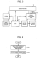
- FIG. 3 is a block diagram illustrating a configuration of a control circuit included in an image reading device 1 according to illustrative embodiments.
- a CPU 20 serving as a control unit to control an image forming sequence and systems in the image reading device 1 also controls initialization such as homing and adjustment of signal characteristics or read images.
- the CPU 20 controls a motor driver 22, a CCD 11 provided on a sensor board 12, an image processing unit 23, and an NVRAM 24.
- the motor driver 22 drives a scanner motor 21 for moving first and second carriages 4 and 5 each provided with an optical reading system including lamps and mirrors.
- the sensor board 12 includes the CCD 11 and black and white level control units thereon.
- the image processing unit 23 digitalizes image data read and sent by the sensor board 12.
- the NVRAM 24 stores data necessary for initialization.
- the CPU 20 receives a detection signal used for homing from a home position sensor 14.
- the image processing unit 23 applies image correction including shading, gamma correction, scaling, filtering, and so forth to the digitalized data of the image read and sent by the sensor board 12.
- the digitalized data to which the image correction is applied is then sent to a writing unit, not shown, to be output.
- the image processing unit 23 detects black and white level data used for obtaining an adjusted value for clamp and gain correction performed by a signal processing unit, not shown, provided on the sensor board 12, based on the digitalized data of the image sent from the sensor board 12. Thereafter, the data thus detected is output to the CPU 20 for feedback.
- the scanner motor 21 includes a pulse motor (a stepping motor) driven by a driving pulse.
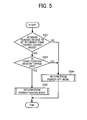
- FIG. 4 is a flowchart illustrating a process performed by the CPU 20 when the image reading device 1 enters the energy-saving mode.
- FIG. 5 is a flowchart illustrating a process to return the image reading device 1 to the active mode from the energy-saving mode.
- the first carriage 4 is moved under a reference whiteboard 3. Thereafter, at S102, the image reading device 1 enters the energy-saving mode. In other words, the first carriage 4 is moved under the reference whiteboard 3 immediately before the image reading device 1 enters the energy-saving mode.
- the CPU 20 confirms whether or not the image reading device 1 is to be returned to the active mode from the energy saving mode.
- the CPU 20 confirms whether or not the home position sensor 14 is turned off.
- the home position sensor 14 is turned off (YES at S202)
- the image reading device 1 is returned to the active mode from the energy-saving mode.
- the image reading device 1 is returned to the active mode from the power-off mode in the same way as the process illustrated in FIG. 2 .
- the home position sensor 14 when the home position sensor 14 is turned on, it means that the first carriage 4 is positioned near a home position 13. Therefore, it is clear that the first carriage 4 is not positioned under the reference whiteboard 3. Accordingly, a process that is the same as that to return the image reading device 1 to the active mode from the power-off mode is performed.
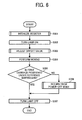
- FIG. 6 is a flowchart illustrating a process to return the image reading device 1 to the active mode from the energy-saving mode performed as a sub-sequence of S203 in the process illustrated in FIG. 5 .
- the integrated circuit is initialized.
- a register of the integrated circuit is initialized.
- a lamp 6 is turned on to read data from the reference whiteboard 3 and adjust a gain value to obtain a predetermined target value.
- an offset value is adjusted. In a similar way as adjustment of the gain value, the offset value is adjusted such that a black level reaches a predetermined target value.
- homing is performed.
- a distance of movement of the first carriage 4 is accurately obtained by counting a pulse to the home position 13.
- the pulse is counted as follows: First, an initial value of a counter provided to the CPU 20 is obtained before the first carriage 4 is moved, and the initial value thus obtained is held as a variable POSCNTCK 1. Next, a counted value of the counter is obtained after homing is performed to move the first carriage 4 to the home position 13. The counted value thus obtained is held as a variable POSCNTCK 2. Then, a pulse during movement of the first carriage 4 is detected from a difference between the variables POSCNTCK 1 and POSCNTCK 2.
- the distance of movement of the first carriage 4 during homing is calculated based on the pulse during the movement of the first carriage 4 thus obtained and an amount of movement of the motor per pulse, and at S305, the CPU 20 determines whether or not the first carriage 4 is positioned under the reference whiteboard 3. In other words, the CPU 20 determines whether or not the first carriage 4 is positioned under the reference whiteboard 3 based on the distance of movement of the first carriage 4 during homing thus calculated.
- the processes of S403 and S404 in FIG. 2 performed by the related-art image reading device can be omitted.
- the time required to return the image reading device 1 to the active mode from the energy-saving mode can be reduced.
- the process to return the image reading device 1 to the active mode from the power-off mode is performed so that the adjusted values can be obtained by reading the reference whiteboard 3.
- the adjusted gain and offset values obtained at previous adjustment may be used. Although accuracy of the gain and offset values is slightly decreased, the time required to return the image reading device 1 to the active mode from the energy-saving mode can be reduced.
- the image reading device 1 may be configured such that the user can select whether to return the image reading device 1 to the active mode from the power-off mode or to perform homing using the gain and offset values adjusted at previous adjustment in the case in which the first carriage 4 is not positioned under the reference whiteboard 3 when the image reading device 1 is returned to the active mode from the energy-saving mode.
- the selection may be performed through a control panel, not shown, provided to the image reading device 1, or a control panel provided to an image forming apparatus.
- the image reading device 1 is described above as a scanner, the image reading device 1 according to the foregoing illustrative embodiments can be effectively applied to an image forming apparatus (such as a copier) including the scanner.
- an image forming apparatus such as a copier
- the first carriage 4 is moved under the reference whiteboard 3 immediately before the energy-saving mode is activated. Accordingly, it is not necessary to perform homing and to move the first carriage 4 under the reference whiteboard 3 when the image reading device 1 is returned to the active mode from the energy-saving mode. As a result, the time required for returning the image reading device 1 to the active mode from the energy-saving mode can be reduced.
- the pulse of the motor is counted at homing after initialization so that the distance between the position of the first carriage 4 when initialization is performed and the home position 13 is reliably obtained.
- the time required for returning the image reading device 1 to the active mode from the energy-saving mode can be reduced even when the first carriage 4 is not positioned under the reference whiteboard 3.
- the pulse of the pulse motor for moving the first carriage 4 is counted when the image reading device 1 is returned to the active mode from the power-off mode or the energy-saving mode, so that the position of the first carriage 4 is reliably obtained when the image reading device 1 is returned to the active mode.
- the different process is performed depending on whether the image reading device 1 is returned to the active mode from the power-off mode or the energy-saving mode. As a result, the time required for returning the image reading device 1 to the active mode from the energy-saving mode can be reduced.
- the first carriage 4 is moved under the reference whiteboard 3 in advance when the image reading device 1 enters the energy-saving mode, the time required for returning the image reading device 1 to the active mode from the energy-saving mode can be reduced.
- the different process is performed when the image reading device 1 is returned from the power-off mode and the energy-saving mode. Specifically, when the image reading device 1 is returned to the active mode from the power-off mode, homing is performed first in a similar way as the image reading device of the related-art. By contrast, when the image reading device 1 is returned to the active mode from the energy-saving mode, it is not necessary to perform homing in the image reading device 1 according to the foregoing illustrative embodiments, so that the time required for returning the image reading device 1 to the active mode from the energy-saving mode can be reduced.
- the pulse to the home position 13 is counted. As a result, it can be reliably determined whether or not the first carriage 4 is positioned under the reference whiteboard 3 when the process to return the image reading device 1 to the active mode from the energy-saving mode is started.
- homing is performed using the previously adjusted gain and offset values, resulting in a reduction in the time required to return the image reading device 1 to the active mode from the energy-saving mode.
Landscapes
- Engineering & Computer Science (AREA)
- Multimedia (AREA)
- Signal Processing (AREA)
- Health & Medical Sciences (AREA)
- Biomedical Technology (AREA)
- General Health & Medical Sciences (AREA)
- Facsimile Scanning Arrangements (AREA)
- Image Processing (AREA)
Abstract
Description
- The present patent application claims priority from Japanese Patent Application No.
2008-044727, filed on February 26, 2008 - Exemplary aspects of the present invention generally relate to an image reading device to read image data from an original document placed on a document stand by scanning it using a carriage driven by a pulse motor, an image reading method, and an image forming apparatus including the image reading device.
- There is increasing demand for a shorter wake-up time from a standby mode to an active mode as well as higher processing speed for image reading devices (such as scanners) included in image forming apparatuses such as copiers and digital multifunction printers.
- When not in operation, the image reading device is generally either in a power-off mode, in which all power supply is turned off, or in an energy-saving mode, in which power is only partially supplied. Specifically, the image reading device enters the power-off mode when a main power source is turned off to shut down the image reading device. By contrast, the image reading device enters the energy-saving mode when a next operation is not performed for a certain period of time after completion of the previous operation. During the energy-saving mode, minimum power is supplied to a minimum number of units to operate a control circuit, and no power is supplied to the rest of the units. A shorter wake-up time is especially required when the image reading device is returned to the active mode from the energy-saving mode. How this shorter wake-up time is accomplished requires a detailed discussion of the structure and operation of a typical image reading device, provided below.
- The image reading device typically includes a lamp, a reflector, a first carriage including a first mirror, a second carriage including second and third mirrors, a home position sensor to detect whether or not the first carriage is positioned at a home position, a contact glass on which an original document is to be placed, a reference whiteboard used for generating shading data and adjusting a reference level, optical elements such as a lens and a CCD, a motor for moving the first and second carriages, and so forth. The first and second carriages are moved in a sub-scanning direction to read data on the reference whiteboard and the original document. When not scanning, the first and second carriages stay at the home position.
-
FIG. 1A is a top view illustrating a related-art image reading device.FIG. 1B is a front view illustrating the related-art image reading device illustrated inFIG. 1A in which first and second carriages are positioned at a home position.FIG. 1C is a view illustrating a detection result output from a home position sensor in which a sub-scanning direction of the carriages is represented by a horizontal axis. - Referring to
FIGS. 1A and 1B , an image reading device 1 includes adocument stand 2, a contact glass, not shown, provided to thedocument stand 2, and areference whiteboard 3 provided on a bottom surface of thedocument stand 2. Thereference whiteboard 3 is provided upstream from the contact glass relative to a direction of movement of a carriage assembly. The carriage assembly includes afirst carriage 4 and asecond carriage 5. Thefirst carriage 4 includes alamp 6 serving as an illumination light source, and afirst mirror 7 to reflect light reflected from an original document. Thesecond carriage 5 includes second andthird mirrors 8 and 9 to direct the light reflected from thefirst mirror 7 to animaging lens 10. The first andsecond carriages second carriages CCD 11 is set to be constant. TheCCD 11 reads an image of the original document, and is provided on asensor board 12. The image of the original document formed by theimaging lens 10 is focused on an imaging surface of theCCD 11 and read by theCCD 11. At this time, data on thereference whiteboard 3 and the original document are read as image data. The first andsecond carriages home position 13 when not scanning. Thehome position 13 is located a certain distance apart from where ahome position sensor 14 is switched from OFF to ON when detecting that thefirst carriage 4 passes thehome position sensor 14. - It should be noted that the
lamp 6, thefirst mirror 7, and the second andthird mirrors 8 and 9 hereinafter serve as optical elements. The first andsecond carriages -
FIG. 2 is a flowchart illustrating a process to return the image reading device 1 from the power-off mode or the energy-saving mode to the active mode. In the image reading device 1 of the related-art, the same process is performed to return the image reading device 1 from the power-off mode and the energy-saving mode to the active mode. Specifically, at S401, integrated circuits (ICs) are initialized to return the image reading device 1 from the power-off mode or the energy-saving mode to the active mode. At S402, thelamp 6 is turned on, and homing is performed at S403. It should be noted that the term "homing" as used in this specification includes relocation of thefirst carriage 4 at thehome position 13. Homing includes two different processes depending on a state of thehome position sensor 14 before homing, as described below. - In a case in which the
home position sensor 14 is switched ON before homing, thefirst carriage 4 is moved to a position where thehome position sensor 14 is switched OFF. Subsequently, a direction of movement of thefirst carriage 4 is reversed when thehome position sensor 14 is switched OFF, and moved until thehome position sensor 14 is switched ON. A pulse is counted from the position where thehome position sensor 14 is switched ON from OFF to place thecarriage 4 at thehome position 13. - By contrast, in a case in which the
home position sensor 14 is switched OFF before homing, thefirst carriage 4 is moved in a direction such that thehome position sensor 14 is switched ON. A pulse is counted from the position where thehome position sensor 14 is switched ON from OFF to place thecarriage 4 at thehome position 13. - After homing, at S404, the
first carriage 4 is moved under thereference whiteboard 3 from thehome position 13 to start initialization. At S405, initialization is performed to initialize the ICs and adjust gain and offset values. At S406, the adjusted gain value and a black level are confirmed and thefirst carriage 4 is moved to thehome position 13. At S407, thelamp 6 is turned off, and the image reading device 1 is now in the active mode and ready to start reading images. - In the above-described image reading device 1, the motor for driving the
first carriage 4 is not activated during the power-off mode and the energy-saving mode. Consequently, thefirst carriage 4 may be moved from thehome position 13 due to vibration applied while, for example, in transit. As a result, homing is required to be performed to move thefirst carriage 4 to thehome position 13 when the image reading device 1 is returned to the active mode. However, because a moving speed of thefirst carriage 4 during homing is constant and slow, a longer time is required to complete homing. - Generally speaking, because a main power source is turned off, the image reading device 1 does not enter the energy-saving mode while in transit. Therefore, it is assumed that the
first carriage 4 does not move much from thehome position 13 during the energy-saving mode due to vibration. However, during the energy-saving mode, thefirst carriage 4 is likely to be positioned where it is positioned immediately before the image reading device 1 enters the energy-saving mode. Consequently, homing is still required to be performed when the image reading device 1 is returned from the energy-saving mode to the active mode. - Although techniques to reduce the time required to restart the image reading device from shut down have been disclosed, those techniques are not effective to reduce the time required to return the image reading device from the energy-saving mode to the active mode.
- In view of the foregoing, illustrative embodiments of the present invention provide an image reading device capable of returning to an active mode from an energy-saving mode within a shorter time, an image reading method, and an image forming apparatus including the image reading device.
- In one illustrative embodiment, an image reading device includes a first carriage including optical elements for reading an image of a document; a second carriage including optical elements for reading the image of the document; a carriage driving unit including a pulse motor to move the first and second carriages; a home position sensor to detect a home position of the first carriage; a reference whiteboard to generate shading data and adjust a reference level to be read by the optical elements; a control unit to control the first and second carriages, the carriage driving unit, the home position sensor, and the reference whiteboard to read the image of the document placed on a contact glass through the optical elements; and a counter to count a pulse of a pulse signal driving the pulse motor. The control unit switches directions of movement of the first carriage based on a result output from the home position sensor when the image reading device is returned to an active mode from an energy-saving mode, and detects a distance of movement of the first carriage based on the pulse counted by the counter.
- Another illustrative embodiment provides an image forming apparatus including the image reading device described above, and an image forming device to form an image on a recording medium based on an image read by the image reading device.
- Yet another illustrative embodiment provides an image reading method for an image reading device. The device includes a first carriage and a second carriage, each carriage containing optical elements for reading an image of a document; a carriage driving unit including a pulse motor to move the first and second carriages; a home position sensor to detect a home position of the first carriage; a reference whiteboard to generate shading data and adjust a reference level to be read by the optical elements; a control unit to control the first and second carriages, the carriage driving unit, the home position sensor, and the reference whiteboard to read the image of the document placed on a contact glass through the optical elements; and a counter to count a pulse of a pulse signal driving the pulse motor. The method includes switching directions of movement of the first carriage based on a result output from the home position sensor when the image reading device is returned to an active mode from an energy-saving mode, and detecting a distance of movement of the first carriage based on the pulse counted by the counter.
- Additional features and advantages of the present invention will be more fully apparent from the following detailed description of illustrative embodiments, the accompanying drawings, and the associated claims.
- A more complete appreciation of the disclosure and many of the attendant advantages thereof will be readily obtained as the same becomes better understood by reference to the following detailed description of illustrative embodiments when considered in connection with the accompanying drawings, wherein:
-
FIG. 1A is a top view illustrating a related-art image reading device; -
FIG. 1B is a front view illustrating the related-art image reading device illustrated inFIG. 1A ; -
FIG. 1C is a view illustrating a detection result output from a home position sensor in which a sub-scanning direction of carriages is represented by a horizontal axis; -
FIG. 2 is a flowchart illustrating a process to return the related-art image reading device to an active mode from a power-off mode or an energy-saving mode; -
FIG. 3 is a block diagram illustrating a configuration of a control circuit included in an image reading device according to illustrative embodiments; -
FIG. 4 is a flowchart illustrating a process to start an energy-saving mode performed by a CPU included in the image reading device according to illustrative embodiments; -
FIG. 5 is a flowchart illustrating a process to return the image reading device to an active mode from the energy saving mode according to illustrative embodiments; and -
FIG. 6 is a flowchart illustrating a process to return the image reading device to the active mode from the energy-saving mode performed as a sub-sequence of S203 in the process illustrated inFIG. 5 . - In describing illustrative embodiments illustrated in the drawings, specific terminology is employed for the sake of clarity. However, the disclosure of this patent specification is not intended to be limited to the specific terminology so selected, and it is to be understood that each specific element includes all technical equivalents that operate in a similar manner and achieve a similar result.
- Illustrative embodiments of the present invention are now described below with reference to the accompanying drawings.
- In a later-described comparative example, illustrative embodiment, and exemplary variation, for the sake of simplicity the same reference numerals are given to identical constituent elements such as parts and materials having the same functions, and redundant descriptions thereof omitted unless otherwise required.
- It should be noted that an image reading device according to illustrative embodiments to be described in detail below includes a configuration substantially similar to that of the image reading device 1 illustrated in
FIG. 1 . Therefore, the same reference numerals as those used inFIG. 1 are assigned to the similar components in the image reading device according to illustrative embodiments, and detailed explanation thereof is omitted. -
FIG. 3 is a block diagram illustrating a configuration of a control circuit included in an image reading device 1 according to illustrative embodiments. ACPU 20 serving as a control unit to control an image forming sequence and systems in the image reading device 1 also controls initialization such as homing and adjustment of signal characteristics or read images. Specifically, referring toFIG. 3 , theCPU 20 controls amotor driver 22, aCCD 11 provided on asensor board 12, animage processing unit 23, and anNVRAM 24. Themotor driver 22 drives ascanner motor 21 for moving first andsecond carriages sensor board 12 includes theCCD 11 and black and white level control units thereon. Theimage processing unit 23 digitalizes image data read and sent by thesensor board 12. TheNVRAM 24 stores data necessary for initialization. TheCPU 20 receives a detection signal used for homing from ahome position sensor 14. Theimage processing unit 23 applies image correction including shading, gamma correction, scaling, filtering, and so forth to the digitalized data of the image read and sent by thesensor board 12. The digitalized data to which the image correction is applied is then sent to a writing unit, not shown, to be output. Further, theimage processing unit 23 detects black and white level data used for obtaining an adjusted value for clamp and gain correction performed by a signal processing unit, not shown, provided on thesensor board 12, based on the digitalized data of the image sent from thesensor board 12. Thereafter, the data thus detected is output to theCPU 20 for feedback. Thescanner motor 21 includes a pulse motor (a stepping motor) driven by a driving pulse. -
FIG. 4 is a flowchart illustrating a process performed by theCPU 20 when the image reading device 1 enters the energy-saving mode.FIG. 5 is a flowchart illustrating a process to return the image reading device 1 to the active mode from the energy-saving mode. - Referring to
FIG. 4 , when the image reading device 1 is switched to the energy-saving mode, at S101, thefirst carriage 4 is moved under areference whiteboard 3. Thereafter, at S102, the image reading device 1 enters the energy-saving mode. In other words, thefirst carriage 4 is moved under thereference whiteboard 3 immediately before the image reading device 1 enters the energy-saving mode. - Referring to
FIG. 5 , when the image reading device 1 is returned to the active mode from the energy-saving mode, at S201, theCPU 20 confirms whether or not the image reading device 1 is to be returned to the active mode from the energy saving mode. When the image reading device 1 is to be returned to the active mode from the energy-saving mode (YES at S201), at S202, theCPU 20 confirms whether or not thehome position sensor 14 is turned off. When thehome position sensor 14 is turned off (YES at S202), at S203, the image reading device 1 is returned to the active mode from the energy-saving mode. By contrast, when thehome position sensor 14 is not turned off (NO at S202), at S204, the image reading device 1 is returned to the active mode from the power-off mode in the same way as the process illustrated inFIG. 2 . Specifically, when thehome position sensor 14 is turned on, it means that thefirst carriage 4 is positioned near ahome position 13. Therefore, it is clear that thefirst carriage 4 is not positioned under thereference whiteboard 3. Accordingly, a process that is the same as that to return the image reading device 1 to the active mode from the power-off mode is performed. -
FIG. 6 is a flowchart illustrating a process to return the image reading device 1 to the active mode from the energy-saving mode performed as a sub-sequence of S203 in the process illustrated inFIG. 5 . Because thefirst carriage 4 is positioned under thereference whiteboard 3 when the image reading device 1 is returned to the active mode from the energy-saving mode, at S301, the integrated circuit is initialized. Here, a register of the integrated circuit is initialized. At S302, alamp 6 is turned on to read data from thereference whiteboard 3 and adjust a gain value to obtain a predetermined target value. Subsequently, at S303, an offset value is adjusted. In a similar way as adjustment of the gain value, the offset value is adjusted such that a black level reaches a predetermined target value. - Thereafter, at S304, homing is performed. At this time, a distance of movement of the
first carriage 4 is accurately obtained by counting a pulse to thehome position 13. The pulse is counted as follows: First, an initial value of a counter provided to theCPU 20 is obtained before thefirst carriage 4 is moved, and the initial value thus obtained is held as a variable POSCNTCK 1. Next, a counted value of the counter is obtained after homing is performed to move thefirst carriage 4 to thehome position 13. The counted value thus obtained is held as avariable POSCNTCK 2. Then, a pulse during movement of thefirst carriage 4 is detected from a difference between the variables POSCNTCK 1 andPOSCNTCK 2. Specifically, the pulse during the movement of thefirst carriage 4 is calculated by a formula DIFF_SPCNT = POSCNTCK 1 -POSCNTCK 2. Thereafter, the distance of movement of thefirst carriage 4 during homing is calculated based on the pulse during the movement of thefirst carriage 4 thus obtained and an amount of movement of the motor per pulse, and at S305, theCPU 20 determines whether or not thefirst carriage 4 is positioned under thereference whiteboard 3. In other words, theCPU 20 determines whether or not thefirst carriage 4 is positioned under thereference whiteboard 3 based on the distance of movement of thefirst carriage 4 during homing thus calculated. - When the
CPU 20 determines that thefirst carriage 4 is positioned under the reference whiteboard 3 (YES at S305), the process to return the image reading device 1 to the active mode from the energy-saving mode is completed. Accordingly, at S307, thelamp 6 is turned off to complete the process. By contrast, when theCPU 20 determines that thefirst carriage 4 is not positioned under the reference whiteboard 3 (NO at S305), the process proceeds to S306 to return the image reading device 1 to the active mode from the power-off mode in the same way as the process illustrated inFIG. 2 . - By returning the image reading device 1 to the active mode as illustrated in
FIG. 6 , the processes of S403 and S404 inFIG. 2 performed by the related-art image reading device can be omitted. As a result, the time required to return the image reading device 1 to the active mode from the energy-saving mode can be reduced. Further, even in a case in which thefirst carriage 4 is not positioned under thereference whiteboard 3 when the image reading device 1 is returned to the active mode from the energy-saving mode, the process to return the image reading device 1 to the active mode from the power-off mode is performed so that the adjusted values can be obtained by reading thereference whiteboard 3. - When further reduction of the time is demanded, the adjusted gain and offset values obtained at previous adjustment may be used. Although accuracy of the gain and offset values is slightly decreased, the time required to return the image reading device 1 to the active mode from the energy-saving mode can be reduced.
- The image reading device 1 may be configured such that the user can select whether to return the image reading device 1 to the active mode from the power-off mode or to perform homing using the gain and offset values adjusted at previous adjustment in the case in which the
first carriage 4 is not positioned under thereference whiteboard 3 when the image reading device 1 is returned to the active mode from the energy-saving mode. The selection may be performed through a control panel, not shown, provided to the image reading device 1, or a control panel provided to an image forming apparatus. - Although the image reading device 1 is described above as a scanner, the image reading device 1 according to the foregoing illustrative embodiments can be effectively applied to an image forming apparatus (such as a copier) including the scanner.
- In the image reading device 1 according to the foregoing illustrative embodiments, the
first carriage 4 is moved under thereference whiteboard 3 immediately before the energy-saving mode is activated. Accordingly, it is not necessary to perform homing and to move thefirst carriage 4 under thereference whiteboard 3 when the image reading device 1 is returned to the active mode from the energy-saving mode. As a result, the time required for returning the image reading device 1 to the active mode from the energy-saving mode can be reduced. - Even in a case in which the
first carriage 4 is moved from under thereference whiteboard 3 due to an impact applied to the image reading device 1 during the energy-saving mode, the pulse of the motor is counted at homing after initialization so that the distance between the position of thefirst carriage 4 when initialization is performed and thehome position 13 is reliably obtained. As a result, the time required for returning the image reading device 1 to the active mode from the energy-saving mode can be reduced even when thefirst carriage 4 is not positioned under thereference whiteboard 3. - The pulse of the pulse motor for moving the
first carriage 4 is counted when the image reading device 1 is returned to the active mode from the power-off mode or the energy-saving mode, so that the position of thefirst carriage 4 is reliably obtained when the image reading device 1 is returned to the active mode. - Although the same process is performed when the image reading device 1 is returned to the active mode from the power-off mode and the energy-saving mode in the image reading device of the related-art, according to the foregoing illustrative embodiments, the different process is performed depending on whether the image reading device 1 is returned to the active mode from the power-off mode or the energy-saving mode. As a result, the time required for returning the image reading device 1 to the active mode from the energy-saving mode can be reduced.
- Further, because the
first carriage 4 is moved under thereference whiteboard 3 in advance when the image reading device 1 enters the energy-saving mode, the time required for returning the image reading device 1 to the active mode from the energy-saving mode can be reduced. - In the image reading device 1 according to the foregoing illustrative embodiments, the different process is performed when the image reading device 1 is returned from the power-off mode and the energy-saving mode. Specifically, when the image reading device 1 is returned to the active mode from the power-off mode, homing is performed first in a similar way as the image reading device of the related-art. By contrast, when the image reading device 1 is returned to the active mode from the energy-saving mode, it is not necessary to perform homing in the image reading device 1 according to the foregoing illustrative embodiments, so that the time required for returning the image reading device 1 to the active mode from the energy-saving mode can be reduced.
- When the image reading device 1 is returned to the active mode from the energy-saving mode, the pulse to the
home position 13 is counted. As a result, it can be reliably determined whether or not thefirst carriage 4 is positioned under thereference whiteboard 3 when the process to return the image reading device 1 to the active mode from the energy-saving mode is started. - In a case in which the
first carriage 4 is not positioned under thereference whiteboard 3 when the image reading device 1 is returned to the active mode from the energy-saving mode, the same process to return the image reading device 1 to the active mode from the power-off mode is performed. Therefore, it is not necessary to add a' new process for the above-described case. - Alternatively, in the case in which the
first carriage 4 is not positioned under thereference whiteboard 3 when the image reading device 1 is returned to the active mode from the energy-saving mode, homing is performed using the previously adjusted gain and offset values, resulting in a reduction in the time required to return the image reading device 1 to the active mode from the energy-saving mode. - Elements and/or features of different illustrative embodiments may be combined with each other and/or substituted for each other within the scope of this disclosure and appended claims.
- Illustrative embodiments being thus described, it will be apparent that the same may be varied in many ways. Such exemplary variations are not to be regarded as a departure from the spirit and scope of the present invention, and all such modifications as would be obvious to one skilled in the art are intended to be included within the scope of the following claims.
- The number of constituent elements, locations, shapes and so forth of the constituent elements are not limited to any of the structure for performing the methodology illustrated in the drawings.
Claims (15)
- An image reading device (1), comprising:a first carriage (4) comprising optical elements for reading an image of a document;a second carriage (5) comprising optical elements for reading the image of the document;a carriage driving unit comprising a pulse motor to move the first and second carriages (4; 5);a home position sensor (14) to detect a home position (13) of the first carriage (4);a reference whiteboard (3) to generate shading data and adjust a reference level to be read by the optical elements;a control unit (20) to control the first and second carriages (4; 5), the carriage driving unit, the home position sensor (14), and the reference whiteboard (3) to read the image of the document placed on a contact glass through the optical elements; anda counter to count a pulse of a pulse signal driving the pulse motor,wherein the control unit (20) switches directions of movement of the first carriage (4) based on a result output from the home position sensor (14) when the image reading device (1) is returned to an active mode from an energy-saving mode, and detects a distance of movement of the first carriage (4) based on the pulse counted by the counter.
- The image reading device (1) according to Claim 1,
wherein the control unit (20) changes an initialization sequence of the image reading device (1) depending on whether the image reading device (1) is returned to the active mode from the energy-saving mode or a power-off mode. - The image reading device according to Claim 1 or 2, wherein the control unit (20) detects the distance of movement of the first carriage (4) based on the pulse counted by the counter to move the first carriage (4) under the reference whiteboard (3) when the image reading device (1) enters the energy-saving mode.
- The image reading device (1) according to any one of Claims 1 to 3, wherein, when the image reading device (1) is returned to the active mode from the energy-saving mode, the control unit (20) initializes an integrated circuit, performs homing of the first carriage (4), determines whether or not the first carriage (4) is positioned under the reference whiteboard (3) during initialization of the integrated circuit, and completes return of the image reading device (1) to the active mode from the energy-saving mode after confirming that the first carriage (4) is positioned under the reference whiteboard (3).
- The image reading device (1) according to Claim 4,
wherein the control unit (20) determines whether or not the first carriage (4) is positioned under the reference whiteboard (3) by calculating a distance of movement of the first carriage (4) to the home position (13) during homing based on a pulse of the pulse motor counted by the counter. - The image reading device (1) according to any one of Claims 1 to 5, wherein the control unit (20) moves the first carriage (4) under the reference whiteboard (3) when determining that the first carriage (4) is positioned at the home position (13) based on the result output from the home position sensor (14), and then moves the first carriage (4) back to the home position (13) after performing predetermined initialization to return the image reading device (1) to the active mode.
- The image reading device (1) according to any one of Claims 1 to 6, wherein the control unit (20) moves the first carriage (4) under the reference whiteboard (3) in a case of determining that the first carriage (4) is not positioned under the reference whiteboard (3) when the image reading device (1) is returned to the active mode from the energy-saving mode, and then moves the first carriage (4) to the home position (13) after adjusting gain and offset values.
- The image reading device (1) according to any one of Claims 1 to 7, wherein the control unit (20) moves the first carriage (4) to the home position (13) using gain and offset values adjusted at previous adjustment as an initial setting value in a case of determining that the first carriage (4) is not positioned under the reference whiteboard (3) when the image reading device (1) is returned to the active mode from the energy-saving mode.
- The image reading device (1) according to any one of Claims 1 to 8, further comprising a selection unit to select whether to move the first carriage (4) to the home position (13) after moving the first carriage (4) under the reference whiteboard (3) and adjusting gain and offset values, or moving the first carriage (4) to the home position (13) using gain and offset values adjusted at previous adjustment as an initial setting value, in a case in which the first carriage (4) is not positioned under the reference whiteboard (3) when the image reading device (1) is returned to the active mode from the energy-saving mode.
- An image forming apparatus, comprising:the image reading device (1) according to any one of Claims 1 to 9; andan image forming device to form an image on a recording medium based on an image read by the image reading device (1).
- An image reading method for an image reading device (1),
the device (1) comprising a first carriage (4) and a second carriage (5), each carriage containing optical elements for reading an image of a document;
a carriage driving unit comprising a pulse motor to move the first and second carriages (4; 5);
a home position sensor (14) to detect a home position (13) of the first carriage (4);
a reference whiteboard (3) to generate shading data and adjust a reference level to be read by the optical elements;
a control unit (20) to control the first and second carriages (4; 5), the carriage driving unit, the home position sensor (14), and the reference whiteboard (3) to read the image of the document placed on a contact glass through the optical elements; and
a counter to count a pulse of a pulse signal driving the pulse motor,
the method comprising:switching directions of movement of the first carriage (4) based on a result output from the home position sensor (14) when the image reading device (1) is returned to an active mode from an energy-saving mode; anddetecting a distance of movement of the first carriage (4) based on the pulse counted by the counter. - The image reading method according to Claim 11,
wherein the control unit (20) changes an initialization sequence of the image reading device (1) depending on whether the image reading device (1) is returned to the active mode from the energy-saving mode or a power-off mode. - The image reading method according to Claim 11 or 12, wherein the control unit (20) detects the distance of movement of the first carriage (4) based on the pulse counted by the counter to move the first carriage (4) under the reference whiteboard (3) when the image reading device (1) enters the energy-saving mode.
- The image reading method according to any one of Claims 11 to 13, wherein, when the image reading device (1) is returned to the active mode from the energy-saving mode, the control unit (20) initializes an integrated circuit, performs homing of the first carriage (4), determines whether or not the first carriage (4) is positioned under the reference whiteboard (3) during initialization of the integrated circuit, and completes return of the image reading device (1) to the active mode from the energy-saving mode after confirming that the first carriage (4) is positioned under the reference whiteboard (3).
- The image reading method according to Claim 14,
wherein the control unit (20) determines whether or not the first carriage (4) is positioned under the reference whiteboard (3) by calculating a distance of movement of the first carriage (4) to the home position (13) during homing based on a pulse of the pulse motor counted by the counter.
Applications Claiming Priority (1)
| Application Number | Priority Date | Filing Date | Title |
|---|---|---|---|
| JP2008044727A JP5089432B2 (en) | 2008-02-26 | 2008-02-26 | Image reading apparatus and image forming apparatus |
Publications (2)
| Publication Number | Publication Date |
|---|---|
| EP2096855A1 true EP2096855A1 (en) | 2009-09-02 |
| EP2096855B1 EP2096855B1 (en) | 2012-08-29 |
Family
ID=40474932
Family Applications (1)
| Application Number | Title | Priority Date | Filing Date |
|---|---|---|---|
| EP09250407A Ceased EP2096855B1 (en) | 2008-02-26 | 2009-02-16 | Image reading device, image reading method, and image forming apparatus including the image reading device |
Country Status (4)
| Country | Link |
|---|---|
| US (1) | US8432585B2 (en) |
| EP (1) | EP2096855B1 (en) |
| JP (1) | JP5089432B2 (en) |
| CN (1) | CN101521717A (en) |
Cited By (2)
| Publication number | Priority date | Publication date | Assignee | Title |
|---|---|---|---|---|
| EP2778798A4 (en) * | 2011-11-08 | 2015-08-19 | Canon Kk | IMAGE FORMING APPARATUS, IMAGE FORMING APPARATUS CONTROLLING METHOD, AND PROGRAM THEREOF |
| EP3200441A1 (en) * | 2016-01-27 | 2017-08-02 | Canon Kabushiki Kaisha | Method for adjusting stop position of reading unit provided in image reading apparatus |
Families Citing this family (6)
| Publication number | Priority date | Publication date | Assignee | Title |
|---|---|---|---|---|
| JP5455685B2 (en) * | 2010-01-29 | 2014-03-26 | キヤノン株式会社 | Equipment with motor |
| JP5750981B2 (en) * | 2010-06-24 | 2015-07-22 | 株式会社リコー | Image processing apparatus and control method thereof |
| JP5640551B2 (en) | 2010-08-23 | 2014-12-17 | 株式会社リコー | Image reading apparatus and image forming apparatus |
| JP5915160B2 (en) | 2011-12-22 | 2016-05-11 | 株式会社リコー | Image reading apparatus and image forming apparatus |
| JP6611513B2 (en) * | 2015-08-07 | 2019-11-27 | キヤノン株式会社 | Image reading apparatus, control method thereof, and program |
| JP6459915B2 (en) * | 2015-11-12 | 2019-01-30 | 京セラドキュメントソリューションズ株式会社 | Image reading apparatus and image forming apparatus |
Citations (4)
| Publication number | Priority date | Publication date | Assignee | Title |
|---|---|---|---|---|
| EP1261193A1 (en) | 2001-05-21 | 2002-11-27 | Ricoh Company, Ltd. | Apparatus and method for controlling the reading operation of a reference white plate in an image reading device having a sheet-through mechanism |
| US20050206976A1 (en) * | 2004-03-19 | 2005-09-22 | Kabushiki Kaisha Toshiba | Method for detecting deterioration of an exposure lamp |
| EP1608145A2 (en) * | 2004-06-17 | 2005-12-21 | Ricoh Company, Ltd. | Method and apparatus for processing image data, computer program and a computer readable storage medium |
| EP1816847A2 (en) | 2006-02-03 | 2007-08-08 | Samsung Electronics Co., Ltd. | Scanning apparatus, driving method therefor, and image forming apparatus having the same |
Family Cites Families (7)
| Publication number | Priority date | Publication date | Assignee | Title |
|---|---|---|---|---|
| JP2002044379A (en) * | 2000-07-25 | 2002-02-08 | Canon Inc | Image reading device and image forming device |
| JP4326166B2 (en) * | 2000-07-31 | 2009-09-02 | 株式会社リコー | Image processing apparatus, scanner initialization processing method, and recording medium storing program for executing the method |
| JP2002112027A (en) * | 2000-09-28 | 2002-04-12 | Ricoh Co Ltd | Image reading device, image processing device, and adjustment value setting method |
| US20050152007A1 (en) * | 2004-01-09 | 2005-07-14 | Cunnagin Stephen K. | Scanner and method for scanning an image or images |
| JP4544462B2 (en) * | 2005-02-28 | 2010-09-15 | 株式会社リコー | Document reading apparatus and image forming apparatus |
| JP4563336B2 (en) * | 2006-04-17 | 2010-10-13 | 株式会社リコー | Image processing apparatus, image reading apparatus, and image forming apparatus |
| JP2008017128A (en) * | 2006-07-05 | 2008-01-24 | Ricoh Co Ltd | Image reading apparatus and initialization processing method |
-
2008
- 2008-02-26 JP JP2008044727A patent/JP5089432B2/en not_active Expired - Fee Related
-
2009
- 2009-02-16 EP EP09250407A patent/EP2096855B1/en not_active Ceased
- 2009-02-19 US US12/388,853 patent/US8432585B2/en active Active
- 2009-02-23 CN CN200910007565A patent/CN101521717A/en active Pending
Patent Citations (4)
| Publication number | Priority date | Publication date | Assignee | Title |
|---|---|---|---|---|
| EP1261193A1 (en) | 2001-05-21 | 2002-11-27 | Ricoh Company, Ltd. | Apparatus and method for controlling the reading operation of a reference white plate in an image reading device having a sheet-through mechanism |
| US20050206976A1 (en) * | 2004-03-19 | 2005-09-22 | Kabushiki Kaisha Toshiba | Method for detecting deterioration of an exposure lamp |
| EP1608145A2 (en) * | 2004-06-17 | 2005-12-21 | Ricoh Company, Ltd. | Method and apparatus for processing image data, computer program and a computer readable storage medium |
| EP1816847A2 (en) | 2006-02-03 | 2007-08-08 | Samsung Electronics Co., Ltd. | Scanning apparatus, driving method therefor, and image forming apparatus having the same |
Cited By (3)
| Publication number | Priority date | Publication date | Assignee | Title |
|---|---|---|---|---|
| EP2778798A4 (en) * | 2011-11-08 | 2015-08-19 | Canon Kk | IMAGE FORMING APPARATUS, IMAGE FORMING APPARATUS CONTROLLING METHOD, AND PROGRAM THEREOF |
| US9621754B2 (en) | 2011-11-08 | 2017-04-11 | Canon Kabushiki Kaisha | Image forming apparatus, method, and medium for affecting startup |
| EP3200441A1 (en) * | 2016-01-27 | 2017-08-02 | Canon Kabushiki Kaisha | Method for adjusting stop position of reading unit provided in image reading apparatus |
Also Published As
| Publication number | Publication date |
|---|---|
| JP5089432B2 (en) | 2012-12-05 |
| EP2096855B1 (en) | 2012-08-29 |
| CN101521717A (en) | 2009-09-02 |
| JP2009206623A (en) | 2009-09-10 |
| US8432585B2 (en) | 2013-04-30 |
| US20090213442A1 (en) | 2009-08-27 |
Similar Documents
| Publication | Publication Date | Title |
|---|---|---|
| EP2096855B1 (en) | Image reading device, image reading method, and image forming apparatus including the image reading device | |
| JP3227191B2 (en) | Image reading device | |
| US6795160B2 (en) | Image reading apparatus and image reading method | |
| US9300832B2 (en) | Image reader and image forming apparatus | |
| JP2002344708A (en) | Image reading device and image forming device | |
| US6104420A (en) | Image forming apparatus and exposure scanning apparatus | |
| US9948815B2 (en) | Image reading apparatus configured to make adjustments when set to read two sides of a document | |
| KR20040070101A (en) | Image scanning apparatus | |
| JPH10319305A (en) | Document reading apparatus and focus adjustment method thereof | |
| US9319554B2 (en) | Image reading device, image forming apparatus, and image reading method | |
| KR20160087682A (en) | Optical image stabilizer and method of controlling the same | |
| US20040184118A1 (en) | Method and apparatus for reading image | |
| JP2003307792A (en) | Image reading device | |
| US7884973B2 (en) | Image reading device, image forming apparatus, image reading method, and computer product | |
| JP2000253220A (en) | Image reading device | |
| JP4511258B2 (en) | Image reading device | |
| CN101646004B (en) | Image reading apparatus and method | |
| JP2010206536A (en) | Image reading apparatus, image reading control method, and image reading control program | |
| JP2002259957A (en) | Image reading device and image forming device | |
| JP2004135214A (en) | Scanner apparatus | |
| JPH11112709A (en) | Dehumidification control device for copier | |
| JP2025002312A (en) | Image reader | |
| JP2024151921A (en) | Image reader | |
| JP4533481B2 (en) | Image reading apparatus and autofocus control method | |
| JPH08167974A (en) | Image reader |
Legal Events
| Date | Code | Title | Description |
|---|---|---|---|
| PUAI | Public reference made under article 153(3) epc to a published international application that has entered the european phase |
Free format text: ORIGINAL CODE: 0009012 |
|
| AK | Designated contracting states |
Kind code of ref document: A1 Designated state(s): AT BE BG CH CY CZ DE DK EE ES FI FR GB GR HR HU IE IS IT LI LT LU LV MC MK MT NL NO PL PT RO SE SI SK TR |
|
| AX | Request for extension of the european patent |
Extension state: AL BA RS |
|
| 17P | Request for examination filed |
Effective date: 20091027 |
|
| AKX | Designation fees paid |
Designated state(s): DE ES FR GB IT NL |
|
| GRAP | Despatch of communication of intention to grant a patent |
Free format text: ORIGINAL CODE: EPIDOSNIGR1 |
|
| GRAS | Grant fee paid |
Free format text: ORIGINAL CODE: EPIDOSNIGR3 |
|
| GRAA | (expected) grant |
Free format text: ORIGINAL CODE: 0009210 |
|
| AK | Designated contracting states |
Kind code of ref document: B1 Designated state(s): DE ES FR GB IT NL |
|
| REG | Reference to a national code |
Ref country code: GB Ref legal event code: FG4D |
|
| REG | Reference to a national code |
Ref country code: DE Ref legal event code: R096 Ref document number: 602009009247 Country of ref document: DE Effective date: 20121025 |
|
| REG | Reference to a national code |
Ref country code: NL Ref legal event code: VDEP Effective date: 20120829 |
|
| PG25 | Lapsed in a contracting state [announced via postgrant information from national office to epo] |
Ref country code: NL Free format text: LAPSE BECAUSE OF FAILURE TO SUBMIT A TRANSLATION OF THE DESCRIPTION OR TO PAY THE FEE WITHIN THE PRESCRIBED TIME-LIMIT Effective date: 20120829 Ref country code: ES Free format text: LAPSE BECAUSE OF FAILURE TO SUBMIT A TRANSLATION OF THE DESCRIPTION OR TO PAY THE FEE WITHIN THE PRESCRIBED TIME-LIMIT Effective date: 20121210 |
|
| PG25 | Lapsed in a contracting state [announced via postgrant information from national office to epo] |
Ref country code: IT Free format text: LAPSE BECAUSE OF FAILURE TO SUBMIT A TRANSLATION OF THE DESCRIPTION OR TO PAY THE FEE WITHIN THE PRESCRIBED TIME-LIMIT Effective date: 20120829 |
|
| PLBE | No opposition filed within time limit |
Free format text: ORIGINAL CODE: 0009261 |
|
| STAA | Information on the status of an ep patent application or granted ep patent |
Free format text: STATUS: NO OPPOSITION FILED WITHIN TIME LIMIT |
|
| 26N | No opposition filed |
Effective date: 20130530 |
|
| REG | Reference to a national code |
Ref country code: DE Ref legal event code: R097 Ref document number: 602009009247 Country of ref document: DE Effective date: 20130530 |
|
| REG | Reference to a national code |
Ref country code: FR Ref legal event code: PLFP Year of fee payment: 8 |
|
| REG | Reference to a national code |
Ref country code: FR Ref legal event code: PLFP Year of fee payment: 9 |
|
| REG | Reference to a national code |
Ref country code: FR Ref legal event code: PLFP Year of fee payment: 10 |
|
| PGFP | Annual fee paid to national office [announced via postgrant information from national office to epo] |
Ref country code: FR Payment date: 20230220 Year of fee payment: 15 |
|
| PGFP | Annual fee paid to national office [announced via postgrant information from national office to epo] |
Ref country code: GB Payment date: 20230220 Year of fee payment: 15 Ref country code: DE Payment date: 20230216 Year of fee payment: 15 |
|
| P01 | Opt-out of the competence of the unified patent court (upc) registered |
Effective date: 20230522 |
|
| REG | Reference to a national code |
Ref country code: DE Ref legal event code: R119 Ref document number: 602009009247 Country of ref document: DE |
|
| GBPC | Gb: european patent ceased through non-payment of renewal fee |
Effective date: 20240216 |
|
| PG25 | Lapsed in a contracting state [announced via postgrant information from national office to epo] |
Ref country code: DE Free format text: LAPSE BECAUSE OF NON-PAYMENT OF DUE FEES Effective date: 20240903 |
|
| PG25 | Lapsed in a contracting state [announced via postgrant information from national office to epo] |
Ref country code: GB Free format text: LAPSE BECAUSE OF NON-PAYMENT OF DUE FEES Effective date: 20240216 |
|
| PG25 | Lapsed in a contracting state [announced via postgrant information from national office to epo] |
Ref country code: FR Free format text: LAPSE BECAUSE OF NON-PAYMENT OF DUE FEES Effective date: 20240229 |
|
| PG25 | Lapsed in a contracting state [announced via postgrant information from national office to epo] |
Ref country code: GB Free format text: LAPSE BECAUSE OF NON-PAYMENT OF DUE FEES Effective date: 20240216 Ref country code: FR Free format text: LAPSE BECAUSE OF NON-PAYMENT OF DUE FEES Effective date: 20240229 Ref country code: DE Free format text: LAPSE BECAUSE OF NON-PAYMENT OF DUE FEES Effective date: 20240903 |