EP2096494A1 - Iterative learning for position control in an exposure apparatus - Google Patents
Iterative learning for position control in an exposure apparatus Download PDFInfo
- Publication number
- EP2096494A1 EP2096494A1 EP09002581A EP09002581A EP2096494A1 EP 2096494 A1 EP2096494 A1 EP 2096494A1 EP 09002581 A EP09002581 A EP 09002581A EP 09002581 A EP09002581 A EP 09002581A EP 2096494 A1 EP2096494 A1 EP 2096494A1
- Authority
- EP
- European Patent Office
- Prior art keywords
- control
- parameter
- filter
- learning
- iterative learning
- Prior art date
- Legal status (The legal status is an assumption and is not a legal conclusion. Google has not performed a legal analysis and makes no representation as to the accuracy of the status listed.)
- Granted
Links
Images






Classifications
-
- G—PHYSICS
- G03—PHOTOGRAPHY; CINEMATOGRAPHY; ANALOGOUS TECHNIQUES USING WAVES OTHER THAN OPTICAL WAVES; ELECTROGRAPHY; HOLOGRAPHY
- G03F—PHOTOMECHANICAL PRODUCTION OF TEXTURED OR PATTERNED SURFACES, e.g. FOR PRINTING, FOR PROCESSING OF SEMICONDUCTOR DEVICES; MATERIALS THEREFOR; ORIGINALS THEREFOR; APPARATUS SPECIALLY ADAPTED THEREFOR
- G03F7/00—Photomechanical, e.g. photolithographic, production of textured or patterned surfaces, e.g. printing surfaces; Materials therefor, e.g. comprising photoresists; Apparatus specially adapted therefor
- G03F7/70—Microphotolithographic exposure; Apparatus therefor
- G03F7/70691—Handling of masks or workpieces
- G03F7/70716—Stages
- G03F7/70725—Stages control
-
- G—PHYSICS
- G03—PHOTOGRAPHY; CINEMATOGRAPHY; ANALOGOUS TECHNIQUES USING WAVES OTHER THAN OPTICAL WAVES; ELECTROGRAPHY; HOLOGRAPHY
- G03F—PHOTOMECHANICAL PRODUCTION OF TEXTURED OR PATTERNED SURFACES, e.g. FOR PRINTING, FOR PROCESSING OF SEMICONDUCTOR DEVICES; MATERIALS THEREFOR; ORIGINALS THEREFOR; APPARATUS SPECIALLY ADAPTED THEREFOR
- G03F7/00—Photomechanical, e.g. photolithographic, production of textured or patterned surfaces, e.g. printing surfaces; Materials therefor, e.g. comprising photoresists; Apparatus specially adapted therefor
- G03F7/70—Microphotolithographic exposure; Apparatus therefor
- G03F7/70691—Handling of masks or workpieces
- G03F7/70775—Position control, e.g. interferometers or encoders for determining the stage position
-
- G—PHYSICS
- G05—CONTROLLING; REGULATING
- G05B—CONTROL OR REGULATING SYSTEMS IN GENERAL; FUNCTIONAL ELEMENTS OF SUCH SYSTEMS; MONITORING OR TESTING ARRANGEMENTS FOR SUCH SYSTEMS OR ELEMENTS
- G05B13/00—Adaptive control systems, i.e. systems automatically adjusting themselves to have a performance which is optimum according to some preassigned criterion
- G05B13/02—Adaptive control systems, i.e. systems automatically adjusting themselves to have a performance which is optimum according to some preassigned criterion electric
- G05B13/0265—Adaptive control systems, i.e. systems automatically adjusting themselves to have a performance which is optimum according to some preassigned criterion electric the criterion being a learning criterion
-
- G—PHYSICS
- G05—CONTROLLING; REGULATING
- G05B—CONTROL OR REGULATING SYSTEMS IN GENERAL; FUNCTIONAL ELEMENTS OF SUCH SYSTEMS; MONITORING OR TESTING ARRANGEMENTS FOR SUCH SYSTEMS OR ELEMENTS
- G05B19/00—Program-control systems
- G05B19/02—Program-control systems electric
- G05B19/18—Numerical control [NC], i.e. automatically operating machines, in particular machine tools, e.g. in a manufacturing environment, so as to execute positioning, movement or co-ordinated operations by means of program data in numerical form
- G05B19/19—Numerical control [NC], i.e. automatically operating machines, in particular machine tools, e.g. in a manufacturing environment, so as to execute positioning, movement or co-ordinated operations by means of program data in numerical form characterised by positioning or contouring control systems, e.g. to control position from one programmed point to another or to control movement along a programmed continuous path
-
- G—PHYSICS
- G05—CONTROLLING; REGULATING
- G05B—CONTROL OR REGULATING SYSTEMS IN GENERAL; FUNCTIONAL ELEMENTS OF SUCH SYSTEMS; MONITORING OR TESTING ARRANGEMENTS FOR SUCH SYSTEMS OR ELEMENTS
- G05B2219/00—Program-control systems
- G05B2219/30—Nc systems
- G05B2219/41—Servomotor, servo controller till figures
- G05B2219/41439—Position error ffw for compensation of speed
-
- G—PHYSICS
- G05—CONTROLLING; REGULATING
- G05B—CONTROL OR REGULATING SYSTEMS IN GENERAL; FUNCTIONAL ELEMENTS OF SUCH SYSTEMS; MONITORING OR TESTING ARRANGEMENTS FOR SUCH SYSTEMS OR ELEMENTS
- G05B2219/00—Program-control systems
- G05B2219/30—Nc systems
- G05B2219/42—Servomotor, servo controller kind till VSS
- G05B2219/42012—H-infinite controller
Definitions
- the present invention relates to a position control apparatus including an iterative learning control circuit suitably applied to a stage unit used in exposure apparatuses or machine tools.
- Iterative learning control is control in which, by repeatedly performing control (a trial) for tracking the trajectory of a target to be controlled, a deviation from the target trajectory is reduced so that high-precision control can be provided.
- learning can be performed by using only an input applied to a target to be controlled and an output of the target. Accordingly, non-linearity that is difficult to include in a control model and a quantization error can be compensated for. It is required for a target to be controlled to have reproducibility so that the same output is obtained from the same input.
- scanning semiconductor exposure apparatuses and industrial robots meet this condition. Accordingly, in order to further improve the control precision, the iterative learning control can be applied to these semiconductor exposure apparatuses and industrial robots.
- the term "learning rule” is referred to as an algorithm in which an output is obtained through a given trial and the next input is updated in accordance with the output.
- One of typical learning rules is a rule in which an input value is generated by multiplying the second derivative value of a deviation by a constant matrix.
- iterative learning control can be performed without using a control target model.
- U.S. Patent No. 7,181,296 B2 describes a method in which, in addition to the above-described model-based learning rule, time-frequency analysis is used so that a robustness filter is time-varied. This method reduces an effect of noise on learning, and therefore, the learning is efficiently carried out.
- an optimal input is obtained by repeatedly carrying out trials. Accordingly, it takes a certain amount of time until an input for precisely tracking the target trajectory is obtained.
- the processing time the throughput
- the throughput is an important factor for their performance. Therefore, it is desirable that the amount of time required for the learning is minimized.
- the learning filter is derived from a linear time-invariant model, and therefore, the learning filter is linear time-invariant (LTI).
- a position control apparatus includes an iterative learning control circuit that reduces the number of iterative trials and the time required for the iterative learning.
- the present invention in its first aspect provides a position control apparatus as specified in claims 1 to 7.
- the present invention in its second aspect provides an exposure apparatus as specified in claim 8.
- the present invention in its third aspect provides a method for manufacturing a device as specified in claim 9.
- the present invention in its fourth aspect provides an iterative learning method as specified in claim 10.
- Fig. 1 is a control block diagram of a position control circuit using linear parameter varying (LPV) iterative learning control.
- LUV linear parameter varying
- Fig. 2 is a flowchart of position control using the LPV iterative learning control.
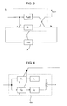
- Fig. 3 is a block diagram of an equivalently converted gain-scheduled H ⁇ control problem used when an LPV learning filter is derived.
- Fig. 4 is a block diagram illustrating a learning filter L(p).
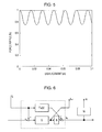
- Fig. 5 is a graph illustrating a relationship between the position of a control target and the force ripple.
- Fig. 6 is a block diagram illustrating a generalized plant including a closed-loop system manipulating a variation in a control target, a robustness filter, and a weight function.
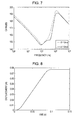
- Fig. 7 is a gain diagram illustrating an LPV iterative learning filter.
- Fig. 8 illustrates a target trajectory of a control target.
- Fig. 9 is a control block diagram of a position control circuit when a zero-phase lowpass filter is used for a robustness filter in LPV iterative learning control.
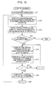
- Fig. 10 is a flowchart of position control performed when a zero-phase lowpass filter is used for a robustness filter in LPV iterative learning control.
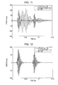
- Fig. 11 illustrates a simulation result according to a first embodiment of the present invention.
- Fig. 12 illustrates a simulation result according to the first embodiment of the present invention.
- Fig. 13 illustrates a simulation result according to the first embodiment of the present invention.
- Fig. 14 illustrates a disturbance force applied to a control target.
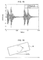
- Fig. 15 illustrates a simulation result according to a second embodiment of the present invention.
- Fig. 16 illustrates the coordinates of a control target according to a third embodiment of the present invention.
- Fig. 17 illustrates the movement and rotation of a control target according to an embodiment of the present invention.
- Fig. 18 illustrates a simulation result according to the third embodiment of the present invention.
- Fig. 19 is a schematic illustration of an exposure apparatus to which an iterative learning control apparatus is applied.
- Fig. 1 is a control block diagram of an exemplary position control apparatus according to a first embodiment of the present invention.
- a position control apparatus 7 controls the position of a control target P(p).
- the position control apparatus 7 includes a feedback controller K, a detecting unit 1 for detecting a position y k of the control target P(p), and a subtracting unit 2 for subtracting the output of the detecting unit 1 from a target value r.
- the position control apparatus 7 further includes an iterative learning control circuit 6 for providing the control target P(p) with a control input obtained through iterative learning.
- the iterative learning control is aimed to reduce a deviation from a target trajectory by repeatedly performing tracking of the target trajectory.
- k represents the iteration trial number.
- the iterative learning control circuit 6 includes a learning filter L(p) (a first filter) for generating a control input, a robustness filter Q (a second filter) for blocking a frequency range unnecessary for the learning operation of the learning filter L(p), and a memory 5 for storing the generated control input.
- a learning filter L(p) (a first filter) for generating a control input
- a robustness filter Q (a second filter) for blocking a frequency range unnecessary for the learning operation of the learning filter L(p)
- a memory 5 for storing the generated control input.
- the target value r and a deviation e k (a k-th deviation) of the output of the detecting unit 1 from the target value r are input to the learning filter L(p).
- the output of the learning filter L(p) is input to an adding unit 4.
- a k-th control input f k is input to the adding unit 4.
- the output of the adding unit 4 is input to the robustness filter Q.
- the output of the robustness filter Q is input to the memory 5 as a (k + 1)th control input f k+1 .
- the control input f k+1 stored in the memory 5 is added to the control target in the form of a feedforward input in a (k + 1)th tracking control operation. That is, the control input f k+1 is added to an output u k+1 of the feedback controller K by an adding unit 3.
- the position control apparatus includes a parameter variation computing unit Z for detecting or estimating a variation in a parameter p of the control target P(p).
- the characteristics of the learning filter L(p) is computed in accordance with the variation in the parameter p.
- information regarding a correlation between the physical quantity of the control target and a variation in the parameter p can be prestored in a memory (not shown) in the form of, for example, a table or a function.
- a variation in the parameter p can be obtained after detecting the physical quantity using, for example, a sensor.
- control target P(p) is expressed as a linear parameter varying (LPV) model including a variation in the parameter.
- LV linear parameter varying
- an LPV system is a plant in which the state space matrix is a function of a parameter p.
- the learning filter L(p) is derived so that condition (8) is satisfied.
- the above-described problem can be illustrated using a control block diagram shown in Fig. 3 (an equivalent conversion diagram of the diagram shown in Fig. 1 ).
- P h (p) denote a portion surrounded by a dotted line.
- the problem is expressed as a gain-scheduled H ⁇ control problem in which L(p) is varied in accordance with a variation in P h (p).
- linear matrix inequality linear time-invariant learning filters L i corresponding to i vertices of the varying parameter can be obtained.
- the linear matrix inequality is denoted as "LMI”
- the linear time-invariant learning filter is denoted as an "LTI learning filter”.
- LTI learning filters L 1 and L 2 invariant filters
- the learning filter L(p) includes an interpolation computing unit.
- Fig. 4 is a control block diagram expressed by equation (10).
- a constant value C 1 represents a coefficient of L1
- a constant value C 2 represents a coefficient of L2.
- Fig. 2 is a flowchart of the iterative learning control.
- step S1 a first trial is carried out.
- control is performed without using the input from the iterative learning control circuit.
- a deviation e 1 is input to the learning filter L(p).
- the output from the learning filter L(p) passes through the robustness filter Q and is stored in the memory 5 as an input f 2 .
- step S2 a k-th trial (k > 1) is carried out.
- a control input and a deviation of an i-th sample in the k-th trial are denoted as f ki and e ki , respectively.
- step S3 a control input f k previously stored in the memory 5 is added to an output U k output from the controller. In this way, the control target is controlled in the k-th trial.
- a (k + 1)th control input is generated through the processing performed in the following steps S4 and S5.
- step S4 the parameter variation computing unit Z detects or estimates a parameter p i of an i-th sample. Using the result of the detection or estimation, the learning filter L i (p i ) is computed. In order to compute the learning filter L i (p i ), the above-described equation (10) is used, for example. In this way, the learning filter L i (p i ) can be computed.
- step S5 the deviation e ki is input to the learning filter L i (p i ).
- the output of the learning filter L i (p i ) is added to the control input f ki .
- the result passes through the robustness filter Q and is stored in the memory 5 as a control input f (k+1)i .
- step S6 the deviation e ki is compared with the maximum value e max of the deviation. If the deviation e ki > e max , then e max is updated.
- step S8 the k-th trial is completed.
- the number of trials required for reducing the deviation to a value less than the predetermined value can be reduced, as compared with existing iterative learning control schemes that do not vary the learning filter. As a result, an amount of time required for iterative learning can be decreased.
- the parameters include the force coefficient of a drive unit that drives a control target.
- the parameter variation computing unit Z computes a variation in the parameter. More specifically, the parameter variation computing unit Z prestores information indicating the correlation between the position of the control target and the force coefficient in a memory (not shown) and computes a variation in the force coefficient using that information and the position of the control target P detected by the detecting unit (sensor) 1. As described below, the parameter can be expressed using an expression including the force coefficient. Accordingly, a variation in the parameter can be computed from the variation in the force coefficient.
- the information indicating the correlation between the position of the control target and the force coefficient can be obtained by detecting the force ripple, as shown in Fig. 5 , while moving the control target and computing the force coefficient from the detected force ripple.
- a method for deriving an LPV model when the parameter p includes the force coefficient and a method for deriving a learning filter L(p) are described next.
- m denote the mass of the control target
- x denote a displacement
- u u denote a force input to the control target
- a denote the force coefficient of the drive unit that drives the control target.
- a generalized plant obtained by introducing a weight function W, a constant ⁇ , and a control value Z 2 into a control system including a closed loop system P cl (P) using the model of equation (22) and a feedback controller and the robustness filter Q can be illustrated as shown in Fig. 6 .
- an LTI learning filter Li corresponding to each of i vertices of a parameter varying on the basis of the gain-scheduled H ⁇ control theory based on the LMI can be derived.
- the robustness filter Q is a first-order lowpass filter having a cut-off frequency of 350 Hz.
- the constant ⁇ is a significantly small constant value.
- the derived LPV learning filter is illustrated in Fig. 7 .
- the solid line and the dotted line represent the learning filters when the parameter p is the upper limit value P max and when the parameter p is the lower limit value P min , respectively.
- an LPV learning filter adaptive to the variation in the parameter p caused by force ripple can be obtained by using equation (10).
- a zero-phase lowpass filter is used for the robustness filter Q. Since a zero-phase lowpass filter cannot perform a real-time operation, the deviation e k and the parameter p are also stored in a memory, as shown in Fig. 9 . A learning operation is performed each time a trial is completed. A particular processing flow is described below with reference to the flowchart shown in Fig. 10 .
- step S11 a first trial is carried out.
- control is performed without using the input from the iterative learning control circuit.
- a deviation e 1 is stored in a memory 11.
- the parameter p 1 is computed by the parameter variation computing unit Z and is stored in a memory 12.
- the deviation e 1 is input to the learning filter L(p).
- the output from the learning filter L(p) passes through the robustness filter Q and is stored in the memory 5 as an input f 2 .
- step S12 a k-th trial (k > 1) is carried out.
- the control input f k previously stored in the memory 5 is added to an output U k output from the controller.
- the control target is controlled.
- a control input f k+1 used for the (k + 1)th trial (k > 1) is generated off-line through the following steps S15 to S18. Note that, since digital control is carried out, a control input and a deviation in an i-th sample in the k-th trial are denoted as f ki and e ki , respectively. Let j denote the total number of samples in one trial. Initially, a maximum value e max of the deviation is set to 0, and a sample number i is set to 0.
- step S13 the deviation e k is stored in the memory 11.
- a parameter p k is computed by the parameter variation computing unit Z, and is stored in the memory 12.
- a maximum value e max of the deviation e k is detected.
- step S15 a parameter P ki of the i-th sample is read from the memory 12. Subsequently, a learning filter L i (P i ) is computed using the readout result. More specifically, the learning filter is computed using equation (10).
- step S16 a deviation e ki of the i-th sample is read from the memory. Subsequently, the deviation e ki is input to the learning filter L i (P i ). The output of the learning filter L i (P i ) is added to the control input f ki . In this way, an output g ki is computed.
- step S18 the output g k passes through the robustness filter Q, which is a zero-phase lowpass filter, and is stored in the memory as a control input f (k+1) .
- a control target is controlled so as to track the target trajectory (the position profile) shown in Fig. 8 .
- a feedforward input obtained by multiplying the acceleration acquired from the position profile by a constant value is provided to the simulation.
- Fig. 11 illustrates the deviation after ten trials have been carried out.
- a solid line represents the iterative learning control using an LPV learning filter.
- a dotted line represents the iterative learning control using a learning filter with a fixed parameter (hereinafter referred to as "LTI iterative learning control").
- the LPV iterative learning control can reduce the deviation, as compared with the LTI iterative learning control. This is because the LPV iterative learning control can be adaptive to the variation in the force by obtaining the value of the force coefficient a at a displacement x from the relationship shown in Fig. 5 , obtaining the parameter p using equation (14), and changing the LPV learning filter.
- Fig. 12 illustrates a comparison of the deviation obtained after 40 trials have been carried out using the LTI iterative learning control and the deviation obtained after 10 trials have been carried out using the LPV iterative learning control.
- the deviation obtained through the LTI iterative learning control is represented by a solid line, while the deviation obtained through the LPV iterative learning control is represented by a dotted line.
- a deviation can be reduced through the repetition number about one fifth of that of the LTI iterative learning control.
- the control input may be corrected using preacquired force ripple data as follows: u u ⁇ 1 a ⁇ u u
- a feedback control system is directly corrected. Accordingly, if the preacquired force ripple data is different from the actual data, the robustness may be degraded.
- a feedforward input is generated through iterative trials. Accordingly, the robustness of the closed-loop system is not degraded.
- Fig. 13 illustrates a simulation result when the actual variation in the force is shifted from the preacquired force ripple data by 3 mm.
- the deviation obtained after 10 trials have been carried out using the LPV iterative learning control is represented by a solid line, while the deviation obtained through the above-described direct compensation of the force coefficient and LTI iterative learning control is represented by a dotted line.
- the deviation obtained through the LTI iterative learning control is large because of the performance degradation of the feedback control system.
- the deviation through the LPV iterative learning control is negligibly degraded, as compared with the response shown in Fig. 11 . Thus, it can be ensured that the LPV iterative learning control is robust.
- the parameters include the disturbance force applied to a control target. Since the disturbance force is not an original parameter of the model, the disturbance force is considered as an equivalent dumping force of the system.
- the parameter variation computing unit Z includes a disturbance observer.
- the disturbance observer estimates a disturbance force using a control input and a displacement.
- the parameter variation computing unit Z can compute a variation in a parameter.
- a method for deriving an LPV model when the parameter p includes a disturbance force is described next.
- m denote the mass of the control target
- x denote a displacement
- u u denote a force input to the control target
- g denote a disturbance force
- an LPV learning filter can be derived.
- the upper limit p max and the lower limit P min are used for the parameter p respectively.
- Fig. 14 illustrates the disturbance applied to a control target.
- the disturbance is a parameter of the simulation.
- the disturbance force is estimated by the disturbance observer.
- the parameter p is computed using the estimated disturbance force, the speed, and equation (30).
- the LPV learning filter is computed in accordance with the parameter p.
- the parameter p does not exceed the upper and lower limits.
- Fig. 15 illustrates the deviation after four trials have been carried out.
- the iterative learning control using an LPV learning filter is represented by a solid line
- the LTI iterative learning control is represented by a dotted line.
- a high tracking performance is obtained in the range from 0.03 sec to 0.05 sec.
- a performance the same as that of the LPV iterative learning control is obtained.
- the LPV iterative learning control estimates the disturbance force and varies the learning filter so as to be adaptive to the disturbance force, the LPV iterative learning control can obtain a high quality learning result. Accordingly, the LPV iterative learning control can reduce the number of iterations.
- the parameter variation computing unit Z includes a sensor (an attitude detecting unit) for detecting the attitude angle of a control target.
- FIG. 16 illustrates the movement of a movable body 86, which is a control target, when the movable body 86 receives a control input u u .
- the abscissa represents the x-axis
- the axis perpendicular to the plane of Fig. 16 represents the y-axis.
- ⁇ y denotes a rotation angle of the movable body 86 about the y-axis.
- the thrust force in the x-axis direction is a component force of the control input u u in a direction parallel to the x-axis direction. Accordingly, the thrust force in the x-axis direction can be given by u u cos ⁇ y .
- an LPV learning filter is derived using a generalized plant.
- the variation range of the parameter p is defined as follows: cos 41 ⁇ ⁇ / 180 m ⁇ p ⁇ cos 0 m
- the rotation angle ⁇ y is controlled by another control system shown in Fig. 17 where is different from a control system that controls the movement in the x-axis direction.
- the rotation angle ⁇ y is directly measured by a sensor. Accordingly, a variation in the parameter can be computed using information from the sensor and equation (38). Thereafter, the LPV filter can be varied.
- the detailed learning flow is the same as that of the first embodiment.
- Fig. 18 illustrates the deviation after four trials have been carried out.
- the iterative learning control using an LPV learning filter is represented by a solid line
- the LTI iterative learning control is represented by a dotted line.
- a small deviation is obtained in the range from 0.03 sec to 0.07 sec.
- the LTI iterative learning control when three more trials have been carried out, a performance the same as that of the LPV iterative learning control is obtained.
- the LPV iterative learning control since the LPV iterative learning control computes a variation in the parameter using the measured value output from the sensor and varies the learning filter in accordance with the computation result, the LPV iterative learning control can obtain a high quality learning result. Accordingly, the LPV iterative learning control can reduce the number of iterations.
- Fig. 19 is a schematic illustration of an example of an exposure apparatus to which one of the position control apparatuses according to the embodiments of the present invention is applied.
- the exposure apparatus is only illustrative. Therefore, the configuration of the exposure apparatus is not limited to the configuration described below.
- An exposure apparatus 100 includes an illumination optical system 81, a movable reticle stage 83 having a reticle 82 mounted thereon, a projection optical system 84, and a movable wafer stage 86 having a wafer 85 mounted thereon.
- the exposure apparatus 100 further includes a sensor 88 that detects the position of the wafer stage 86.
- Light is emitted from the illumination optical system 81 onto the wafer (substrate) 85 via the reticle (original) 82 and the projection optical system 84.
- a reduced pattern of the reticle 82 is projected onto a wafer by the projection optical system 84.
- the image of the reduced pattern is formed on the wafer.
- the exposure apparatus 100 further includes a control board 80 disposed in a control box.
- the control board 80 includes the position control apparatus 7 according to one of the above-described embodiments.
- An existing DSP system can be used for the control board 80.
- the control board 80 is connected to the sensor 88, a main central processing unit (CPU) (not shown) of the exposure apparatus 100, and a driver (not shown) that drives the stage so as to be communicable with these components.
- CPU central processing unit
- the exposure apparatus 100 detects or estimates a variation in a parameter on the basis of a position signal output from, for example, the sensor 88. Thereafter, the exposure apparatus 100 carries out the iterative learning control while taking into account a variation in the parameter so as to control the position of the wafer stage 86.
- the exposure apparatus 100 Before the exposure apparatus 100 starts an actual exposure operation, the exposure apparatus 100 can drive the wafer stage 86 k times. In this way, the exposure apparatus 100 can start the actual exposure operation after the maximum value e max of the deviation becomes sufficiently small. After the maximum value e max of the deviation becomes sufficiently small, the exposure apparatus 100 may or may not update a control input f k .
- the position control apparatus in place of controlling the wafer stage 86, the position control apparatus according to one of the above-described embodiments may be used for controlling the reticle stage 83.
- a device e.g., a semiconductor integrated circuit device or a liquid crystal display device
- a method for manufacturing the device includes a step of performing an exposure operation on a wafer (a substrate) having a photosensitive agent applied thereon using the exposure apparatus 100. Conventional processing steps, such as developing the substrate, may then be applied to complete the manufacturing of the device.
Landscapes
- Engineering & Computer Science (AREA)
- Physics & Mathematics (AREA)
- General Physics & Mathematics (AREA)
- Artificial Intelligence (AREA)
- Automation & Control Theory (AREA)
- Evolutionary Computation (AREA)
- Software Systems (AREA)
- Medical Informatics (AREA)
- Computer Vision & Pattern Recognition (AREA)
- Health & Medical Sciences (AREA)
- Human Computer Interaction (AREA)
- Manufacturing & Machinery (AREA)
- Feedback Control In General (AREA)
- Exposure And Positioning Against Photoresist Photosensitive Materials (AREA)
- Exposure Of Semiconductors, Excluding Electron Or Ion Beam Exposure (AREA)
- Control Of Position Or Direction (AREA)
Abstract
Description
- The present invention relates to a position control apparatus including an iterative learning control circuit suitably applied to a stage unit used in exposure apparatuses or machine tools.
- Iterative learning control is control in which, by repeatedly performing control (a trial) for tracking the trajectory of a target to be controlled, a deviation from the target trajectory is reduced so that high-precision control can be provided. In general, in the iterative learning control, learning can be performed by using only an input applied to a target to be controlled and an output of the target. Accordingly, non-linearity that is difficult to include in a control model and a quantization error can be compensated for. It is required for a target to be controlled to have reproducibility so that the same output is obtained from the same input. In general, scanning semiconductor exposure apparatuses and industrial robots meet this condition. Accordingly, in order to further improve the control precision, the iterative learning control can be applied to these semiconductor exposure apparatuses and industrial robots. Several applications have been proposed.
- In the iterative learning control, the term "learning rule" is referred to as an algorithm in which an output is obtained through a given trial and the next input is updated in accordance with the output. One of typical learning rules is a rule in which an input value is generated by multiplying the second derivative value of a deviation by a constant matrix. In addition, by using a PD compensator for a learning rule, iterative learning control can be performed without using a control target model.
- Furthermore, De Roover and his colleagues obtain such a learning filter by using an H∞ control theory (Synthesis of robust multivariable iterative learning controllers with application to a wafer stage motion system, DICK DE ROOVER and OKKO H. BOSGRA, International Journal of Control, 2000, Vol. 73, No. 10, pp. 968 - 979).
- Still furthermore,
U.S. Patent No. 7,181,296 B2 describes a method in which, in addition to the above-described model-based learning rule, time-frequency analysis is used so that a robustness filter is time-varied. This method reduces an effect of noise on learning, and therefore, the learning is efficiently carried out. - In iterative learning control, an optimal input is obtained by repeatedly carrying out trials. Accordingly, it takes a certain amount of time until an input for precisely tracking the target trajectory is obtained. For example, for semiconductor exposure apparatuses, the processing time (the throughput) is an important factor for their performance. Therefore, it is desirable that the amount of time required for the learning is minimized.
- In order to reduce the number of trials and obtain an optimal input, information about the target to be controlled can be actively used. However, in the above-described document, the learning filter is derived from a linear time-invariant model, and therefore, the learning filter is linear time-invariant (LTI).
- Accordingly, if the parameters of a model are varied during a trial, the consistency between the model and the learning filter is not ensured. As a result, the learning performance is degraded, and therefore, the number of iterative trials and learning time increase.
- According to an aspect of the present invention, a position control apparatus includes an iterative learning control circuit that reduces the number of iterative trials and the time required for the iterative learning.
- The present invention in its first aspect provides a position control apparatus as specified in
claims 1 to 7. - The present invention in its second aspect provides an exposure apparatus as specified in
claim 8. - The present invention in its third aspect provides a method for manufacturing a device as specified in
claim 9. - The present invention in its fourth aspect provides an iterative learning method as specified in
claim 10. - Further features of the present invention will become apparent from the following description of exemplary embodiments with reference to the attached drawings.
-
Fig. 1 is a control block diagram of a position control circuit using linear parameter varying (LPV) iterative learning control. -
Fig. 2 is a flowchart of position control using the LPV iterative learning control. -
Fig. 3 is a block diagram of an equivalently converted gain-scheduled H∞ control problem used when an LPV learning filter is derived. -
Fig. 4 is a block diagram illustrating a learning filter L(p). -
Fig. 5 is a graph illustrating a relationship between the position of a control target and the force ripple. -
Fig. 6 is a block diagram illustrating a generalized plant including a closed-loop system manipulating a variation in a control target, a robustness filter, and a weight function. -
Fig. 7 is a gain diagram illustrating an LPV iterative learning filter. -
Fig. 8 illustrates a target trajectory of a control target. -
Fig. 9 is a control block diagram of a position control circuit when a zero-phase lowpass filter is used for a robustness filter in LPV iterative learning control. -
Fig. 10 is a flowchart of position control performed when a zero-phase lowpass filter is used for a robustness filter in LPV iterative learning control. -
Fig. 11 illustrates a simulation result according to a first embodiment of the present invention. -
Fig. 12 illustrates a simulation result according to the first embodiment of the present invention. -
Fig. 13 illustrates a simulation result according to the first embodiment of the present invention. -
Fig. 14 illustrates a disturbance force applied to a control target. -
Fig. 15 illustrates a simulation result according to a second embodiment of the present invention. -
Fig. 16 illustrates the coordinates of a control target according to a third embodiment of the present invention. -
Fig. 17 illustrates the movement and rotation of a control target according to an embodiment of the present invention. -
Fig. 18 illustrates a simulation result according to the third embodiment of the present invention. -
Fig. 19 is a schematic illustration of an exposure apparatus to which an iterative learning control apparatus is applied. -
Fig. 1 is a control block diagram of an exemplary position control apparatus according to a first embodiment of the present invention. Aposition control apparatus 7 controls the position of a control target P(p). Theposition control apparatus 7 includes a feedback controller K, a detectingunit 1 for detecting a position yk of the control target P(p), and asubtracting unit 2 for subtracting the output of the detectingunit 1 from a target value r. Theposition control apparatus 7 further includes an iterativelearning control circuit 6 for providing the control target P(p) with a control input obtained through iterative learning. - The iterative learning control is aimed to reduce a deviation from a target trajectory by repeatedly performing tracking of the target trajectory. Hereinafter, k represents the iteration trial number.
- The iterative
learning control circuit 6 includes a learning filter L(p) (a first filter) for generating a control input, a robustness filter Q (a second filter) for blocking a frequency range unnecessary for the learning operation of the learning filter L(p), and amemory 5 for storing the generated control input. - The target value r and a deviation ek (a k-th deviation) of the output of the detecting
unit 1 from the target value r are input to the learning filter L(p). The output of the learning filter L(p) is input to an addingunit 4. In addition, a k-th control input fk is input to the addingunit 4. The output of the addingunit 4 is input to the robustness filter Q. The output of the robustness filter Q is input to thememory 5 as a (k + 1)th control input fk+1. The control input fk+1 stored in thememory 5 is added to the control target in the form of a feedforward input in a (k + 1)th tracking control operation. That is, the control input fk+1 is added to an output uk+1 of the feedback controller K by an addingunit 3. - According to the first embodiment of the present invention, the position control apparatus includes a parameter variation computing unit Z for detecting or estimating a variation in a parameter p of the control target P(p). The characteristics of the learning filter L(p) is computed in accordance with the variation in the parameter p.
- In order to detect or estimate a variation in the parameter p, for example, information regarding a correlation between the physical quantity of the control target and a variation in the parameter p can be prestored in a memory (not shown) in the form of, for example, a table or a function. During the tracking control, a variation in the parameter p can be obtained after detecting the physical quantity using, for example, a sensor.
- A method for deriving the learning filter L(p) is described next.
- In order to derive the learning filter L(p), the control target P(p) is expressed as a linear parameter varying (LPV) model including a variation in the parameter.
- In general, an LPV system is a plant in which the state space matrix is a function of a parameter p. The LPV system is expressed as follows:


- Here, in the feedback control system shown in
Fig. 1 , a closed loop system Pcl(p) of the control target P(p) and the feedback controller K is expressed as follows:
where the feedback controller K is a fixed feedback controller that does not vary in accordance with a variation in the parameter. - According to the present embodiment, the learning filter L(p) is an LPV system and is expressed as follows:


- In addition, for the iterative learning control circuit shown in
Fig. 1 , the control input is defined as follows:
- Using the above-described equations, the relationship between deviations ek+1 and ek is expressed as follows:

- In order to converge the deviation through iterative learning, the following condition is satisfied:

- The learning filter L(p) is derived so that condition (8) is satisfied. The above-described problem can be illustrated using a control block diagram shown in
Fig. 3 (an equivalent conversion diagram of the diagram shown inFig. 1 ). As shown inFig. 3 , let Ph(p) denote a portion surrounded by a dotted line. Then, the problem is expressed as a gain-scheduled H∞ control problem in which L(p) is varied in accordance with a variation in Ph(p). Accordingly, by using a linear matrix inequality, linear time-invariant learning filters Li corresponding to i vertices of the varying parameter can be obtained. Hereinafter, the linear matrix inequality is denoted as "LMI", and the linear time-invariant learning filter is denoted as an "LTI learning filter". - The LTI learning filter Li is expressed as the following matrix:

- For example, when the number of parameters that vary is one, the number of vertices of the parameter is two. Accordingly, two LTI learning filters L1 and L2 (invariant filters) corresponding to the two vertices can be obtained.
- Here, by interpolating values between the two LTI learning filters using the following interpolation expression, the learning filter L(p) can be computed in accordance with a variation in the parameter p:

where Pmin represents the lower limit value, and Pmax represents the upper limit value. - That is, the learning filter L(p) includes an interpolation computing unit.
-
Fig. 4 is a control block diagram expressed by equation (10). InFig. 4 , a constant value C1 represents a coefficient of L1, and a constant value C2 represents a coefficient of L2. By adding the product of the constant value C1 and a learning filter L1 to the product of the constant value C2 and a learning filter L2, the LPV learning filter L(p) can be obtained. - The flow of iterative learning control performed by the position control apparatus shown in
Fig. 1 is described below. -
Fig. 2 is a flowchart of the iterative learning control. - In step S1, a first trial is carried out. In step S1, control is performed without using the input from the iterative learning control circuit. A deviation e1 is input to the learning filter L(p). The output from the learning filter L(p) passes through the robustness filter Q and is stored in the
memory 5 as an input f2. - In step S2, a k-th trial (k > 1) is carried out. Note that, since digital control is carried out, a control input and a deviation of an i-th sample in the k-th trial are denoted as fki and eki, respectively. Let j denote the total number of samples in one trial. Initially, a maximum value emax of the deviation is set to 0, and a sample number i is set to 0.
- In step S3, a control input fk previously stored in the
memory 5 is added to an output Uk output from the controller. In this way, the control target is controlled in the k-th trial. - In addition, in the k-th trial, a (k + 1)th control input is generated through the processing performed in the following steps S4 and S5.
- In step S4, the parameter variation computing unit Z detects or estimates a parameter pi of an i-th sample. Using the result of the detection or estimation, the learning filter Li(pi) is computed. In order to compute the learning filter Li(pi), the above-described equation (10) is used, for example. In this way, the learning filter Li(pi) can be computed.
- In step S5, the deviation eki is input to the learning filter Li(pi). The output of the learning filter Li(pi) is added to the control input fki. Thereafter, the result passes through the robustness filter Q and is stored in the
memory 5 as a control input f(k+1)i. - In step S6, the deviation eki is compared with the maximum value emax of the deviation. If the deviation eki > emax, then emax is updated.
- If, in step S7, j < i (YES in step S7), then the processing proceeds to step S8. However, if j ≥ i (NO in step S7), i = i + 1 and, subsequently, the processing proceeds to step S2.
- In step S8, the k-th trial is completed.
- In step S9, the maximum value emax of the deviation is compared with a predetermined setting value. If the maximum value emax is smaller than or equal to the predetermined setting value (YES in step S9), it is determined that the deviation is sufficiently small. Therefore, the learning operation is completed. However, if the maximum value emax is greater than the predetermined setting value (NO in step S9), k = k + 1 and, subsequently, the processing proceeds to step S2.
- By controlling the position using the above-described iterative learning control scheme, the number of trials required for reducing the deviation to a value less than the predetermined value can be reduced, as compared with existing iterative learning control schemes that do not vary the learning filter. As a result, an amount of time required for iterative learning can be decreased.
- Exemplary suitable parameters and the resultant effective data are described with reference to the following first to third embodiments of the present invention.
- In the first embodiment, the parameters include the force coefficient of a drive unit that drives a control target.
- A position control apparatus according to the present embodiment is described next with reference to
Fig. 1 . Note that descriptions already made with reference toFig. 1 are not repeated. The parameter variation computing unit Z computes a variation in the parameter. More specifically, the parameter variation computing unit Z prestores information indicating the correlation between the position of the control target and the force coefficient in a memory (not shown) and computes a variation in the force coefficient using that information and the position of the control target P detected by the detecting unit (sensor) 1. As described below, the parameter can be expressed using an expression including the force coefficient. Accordingly, a variation in the parameter can be computed from the variation in the force coefficient. - For example, the information indicating the correlation between the position of the control target and the force coefficient can be obtained by detecting the force ripple, as shown in
Fig. 5 , while moving the control target and computing the force coefficient from the detected force ripple. - A method for deriving an LPV model when the parameter p includes the force coefficient and a method for deriving a learning filter L(p) are described next.
- Let m denote the mass of the control target, x denote a displacement, uu denote a force input to the control target, and a denote the force coefficient of the drive unit that drives the control target. Then, the control target is modeled as follows:

- A procedure for transforming this model into an Affine parameter-dependent model, which is one of LPV models, is described next.
- First, the state vector is defined as:

- Subsequently, the state equation is obtained using equation (11) as follows:

- When setting:

then
- Here, an output equation y is defined as follows:

- In addition, the amplifying characteristics of an actuator are expressed using the following state equation and output equation:


- Here, the following augmented plant of equations (15) and (16) can be obtained using xw = [x xf]T:


- Then, the system matrix can be written as:

- In this way, the system matrix can be expressed using the matrix A0 that does not include the parameter p and the matrix A1 that has only coefficients of the parameter p. Thus, equation (21) serves as the following affine parameter-dependent model:

- A generalized plant obtained by introducing a weight function W, a constant δ, and a control value Z2 into a control system including a closed loop system Pcl(P) using the model of equation (22) and a feedback controller and the robustness filter Q can be illustrated as shown in
Fig. 6 . Accordingly, an LTI learning filter Li corresponding to each of i vertices of a parameter varying on the basis of the gain-scheduled H∞ control theory based on the LMI can be derived. Note that, in this embodiment, the robustness filter Q is a first-order lowpass filter having a cut-off frequency of 350 Hz. - In addition, the weight function W is defined as:

Furthermore, the constant δ is a significantly small constant value. - If the range of a variation in the force coefficient a is set to:

then the parameter p varies in the following range:
- The derived LPV learning filter is illustrated in
Fig. 7 . The solid line and the dotted line represent the learning filters when the parameter p is the upper limit value Pmax and when the parameter p is the lower limit value Pmin, respectively. Let L1 and L2 denote the learning filters. Then, an LPV learning filter adaptive to the variation in the parameter p caused by force ripple can be obtained by using equation (10). - In addition, according to the present embodiment, a zero-phase lowpass filter is used for the robustness filter Q. Since a zero-phase lowpass filter cannot perform a real-time operation, the deviation ek and the parameter p are also stored in a memory, as shown in
Fig. 9 . A learning operation is performed each time a trial is completed. A particular processing flow is described below with reference to the flowchart shown inFig. 10 . - In step S11, a first trial is carried out. In step S11, control is performed without using the input from the iterative learning control circuit. A deviation e1 is stored in a
memory 11. In addition, the parameter p1 is computed by the parameter variation computing unit Z and is stored in amemory 12. The deviation e1 is input to the learning filter L(p). The output from the learning filter L(p) passes through the robustness filter Q and is stored in thememory 5 as an input f2. - In step S12, a k-th trial (k > 1) is carried out. At that time, the control input fk previously stored in the
memory 5 is added to an output Uk output from the controller. In this way, in the k-th trial, the control target is controlled. In addition, in the k-th trial, a control input fk+1 used for the (k + 1)th trial (k > 1) is generated off-line through the following steps S15 to S18. Note that, since digital control is carried out, a control input and a deviation in an i-th sample in the k-th trial are denoted as fki and eki, respectively. Let j denote the total number of samples in one trial. Initially, a maximum value emax of the deviation is set to 0, and a sample number i is set to 0. - In step S13, the deviation ek is stored in the
memory 11. In addition, a parameter pk is computed by the parameter variation computing unit Z, and is stored in thememory 12. Furthermore, a maximum value emax of the deviation ek is detected. - In step S14, the maximum value emax of the deviation is compared with a predetermined setting value. If the maximum value emax is smaller than or equal to the predetermined setting value (YES in step S14), it is determined that the deviation is sufficiently small. Therefore, the learning operation is completed. However, if the maximum value emax of the deviation is greater than the predetermined setting value (NO in step S14), then k is incremented by 1 (which conveniently may be written k = k + 1). Thereafter, the processing proceeds to step S15.
- In step S15, a parameter Pki of the i-th sample is read from the
memory 12. Subsequently, a learning filter Li(Pi) is computed using the readout result. More specifically, the learning filter is computed using equation (10). - In step S16, a deviation eki of the i-th sample is read from the memory. Subsequently, the deviation eki is input to the learning filter Li(Pi). The output of the learning filter Li(Pi) is added to the control input fki. In this way, an output gki is computed.
- If, in step S17, j < i (YES in step S17), then the processing proceeds to step S18. However, if j ≥ i (NO in step S17), i = i + 1. Subsequently, the processing proceeds to step S15.
- In step S18, the output gk passes through the robustness filter Q, which is a zero-phase lowpass filter, and is stored in the memory as a control input f(k+1).
- In step S19, k = k + 1 and, subsequently, the processing proceeds to step S12, where the next trial is started. By repeating the above-described steps, the learning control is carried out.
- The result of simulation according to the present embodiment is described below.
- In this simulation, a control target is controlled so as to track the target trajectory (the position profile) shown in
Fig. 8 . Note that, in addition to the control input obtained through the above-described iterative learning and the feedback input, a feedforward input obtained by multiplying the acceleration acquired from the position profile by a constant value is provided to the simulation. -
Fig. 11 illustrates the deviation after ten trials have been carried out. InFig. 11 , a solid line represents the iterative learning control using an LPV learning filter. A dotted line represents the iterative learning control using a learning filter with a fixed parameter (hereinafter referred to as "LTI iterative learning control"). As can be seen fromFig. 11 , the LPV iterative learning control can reduce the deviation, as compared with the LTI iterative learning control. This is because the LPV iterative learning control can be adaptive to the variation in the force by obtaining the value of the force coefficient a at a displacement x from the relationship shown inFig. 5 , obtaining the parameter p using equation (14), and changing the LPV learning filter. -
Fig. 12 illustrates a comparison of the deviation obtained after 40 trials have been carried out using the LTI iterative learning control and the deviation obtained after 10 trials have been carried out using the LPV iterative learning control. The deviation obtained through the LTI iterative learning control is represented by a solid line, while the deviation obtained through the LPV iterative learning control is represented by a dotted line. As can be seen fromFig. 12 , by using the LPV iterative learning control, a deviation can be reduced through the repetition number about one fifth of that of the LTI iterative learning control. - In addition, in order to compensate for the variation in the force, the control input may be corrected using preacquired force ripple data as follows:

However, in this technique, a feedback control system is directly corrected. Accordingly, if the preacquired force ripple data is different from the actual data, the robustness may be degraded. In contrast, in the LPV iterative learning control, a feedforward input is generated through iterative trials. Accordingly, the robustness of the closed-loop system is not degraded. -
Fig. 13 illustrates a simulation result when the actual variation in the force is shifted from the preacquired force ripple data by 3 mm. The deviation obtained after 10 trials have been carried out using the LPV iterative learning control is represented by a solid line, while the deviation obtained through the above-described direct compensation of the force coefficient and LTI iterative learning control is represented by a dotted line. The deviation obtained through the LTI iterative learning control is large because of the performance degradation of the feedback control system. However, the deviation through the LPV iterative learning control is negligibly degraded, as compared with the response shown inFig. 11 . Thus, it can be ensured that the LPV iterative learning control is robust. - In the second embodiment, the parameters include the disturbance force applied to a control target. Since the disturbance force is not an original parameter of the model, the disturbance force is considered as an equivalent dumping force of the system.
- A position control apparatus according to the present embodiment is described next with reference to
Fig. 1 . Note that descriptions already made with reference toFig. 1 are not repeated. The parameter variation computing unit Z includes a disturbance observer. The disturbance observer estimates a disturbance force using a control input and a displacement. By using the estimated disturbance force, the parameter variation computing unit Z can compute a variation in a parameter. - A method for deriving an LPV model when the parameter p includes a disturbance force is described next.
- Let m denote the mass of the control target, x denote a displacement, uu denote a force input to the control target, and g denote a disturbance force. Then, the control target is modeled as follows:

- Here, by applying the following extended linearization:

the state equation of equation (27) can be obtained as follows:
Thus, a disturbance force can be introduced into a system matrix. - By setting:


and forming the augmented plant of the amplifying characteristics of an actuator, the following affine parameter-dependent model that varies in accordance with the disturbance force can be obtained, as in the first embodiment:
- Then, by using a generalized plant similar to that of the first embodiment, an LPV learning filter can be derived. The changing range of the parameter p is set to:

- If the parameter p exceeds the upper limit pmax and the lower limit Pmin, then the upper limit pmax and the lower limit Pmin are used for the parameter p respectively.
- The simulation result of the present embodiment is described below.
-
Fig. 14 illustrates the disturbance applied to a control target. The disturbance is a parameter of the simulation. The disturbance force is estimated by the disturbance observer. Thereafter, the parameter p is computed using the estimated disturbance force, the speed, and equation (30). Subsequently, the LPV learning filter is computed in accordance with the parameter p. - Since the detailed learning flow is the same as that of the first embodiment, descriptions thereof are not repeated.
- Note that, in the simulation using the disturbance shown in
Fig. 14 and the profile shown inFig. 8 , the parameter p does not exceed the upper and lower limits. -
Fig. 15 illustrates the deviation after four trials have been carried out. The iterative learning control using an LPV learning filter is represented by a solid line, and the LTI iterative learning control is represented by a dotted line. As can be seen fromFig. 15 , in the LPV iterative learning control, a high tracking performance is obtained in the range from 0.03 sec to 0.05 sec. In contrast, in the LTI iterative learning control, when two more trials have been carried out, a performance the same as that of the LPV iterative learning control is obtained. As described above, since the LPV iterative learning control estimates the disturbance force and varies the learning filter so as to be adaptive to the disturbance force, the LPV iterative learning control can obtain a high quality learning result. Accordingly, the LPV iterative learning control can reduce the number of iterations. - In the third embodiment, the parameters including a variation in the attitude angle of a control target is described with reference to
Fig. 1 . Note that descriptions already made with reference toFig. 1 are not repeated. - The parameter variation computing unit Z includes a sensor (an attitude detecting unit) for detecting the attitude angle of a control target.
- A method for deriving an LPV model when the parameter p includes the attitude angle of a control target is described next.
Fig. 16 illustrates the movement of amovable body 86, which is a control target, when themovable body 86 receives a control input uu. InFig. 16 , the abscissa represents the x-axis, and the axis perpendicular to the plane ofFig. 16 represents the y-axis. In addition, θy denotes a rotation angle of themovable body 86 about the y-axis. - As shown in
Fig. 16 , when a thrust force is generated in a direction parallel to a bottom surface of the control target, the thrust force in the x-axis direction is a component force of the control input uu in a direction parallel to the x-axis direction. Accordingly, the thrust force in the x-axis direction can be given by uucosθy. - The state equation of the control target is expressed as follows:

- When setting:

and obtaining the augmented plant of the state equation with the amplifying characteristics of an actuator, as in the first embodiment, then the following affine parameter-dependent model that varies in accordance with the rotation angle can be obtained:
- Subsequently, as in the first embodiment, an LPV learning filter is derived using a generalized plant. At that time, the variation range of the parameter p is defined as follows:

- The simulation result of the present embodiment is described below.
- In the present embodiment, the rotation angle θy is controlled by another control system shown in
Fig. 17 where is different from a control system that controls the movement in the x-axis direction. In addition, the rotation angle θy is directly measured by a sensor. Accordingly, a variation in the parameter can be computed using information from the sensor and equation (38). Thereafter, the LPV filter can be varied. - The detailed learning flow is the same as that of the first embodiment.
-
Fig. 18 illustrates the deviation after four trials have been carried out. The iterative learning control using an LPV learning filter is represented by a solid line, and the LTI iterative learning control is represented by a dotted line. As can be seen fromFig. 18 , in the LPV iterative learning control, a small deviation is obtained in the range from 0.03 sec to 0.07 sec. In contrast, in the LTI iterative learning control, when three more trials have been carried out, a performance the same as that of the LPV iterative learning control is obtained. As described above, since the LPV iterative learning control computes a variation in the parameter using the measured value output from the sensor and varies the learning filter in accordance with the computation result, the LPV iterative learning control can obtain a high quality learning result. Accordingly, the LPV iterative learning control can reduce the number of iterations. -
Fig. 19 is a schematic illustration of an example of an exposure apparatus to which one of the position control apparatuses according to the embodiments of the present invention is applied. According to the present embodiment, the exposure apparatus is only illustrative. Therefore, the configuration of the exposure apparatus is not limited to the configuration described below. - An
exposure apparatus 100 includes an illuminationoptical system 81, amovable reticle stage 83 having areticle 82 mounted thereon, a projectionoptical system 84, and amovable wafer stage 86 having awafer 85 mounted thereon. Theexposure apparatus 100 further includes asensor 88 that detects the position of thewafer stage 86. - Light is emitted from the illumination
optical system 81 onto the wafer (substrate) 85 via the reticle (original) 82 and the projectionoptical system 84. In this way, a reduced pattern of thereticle 82 is projected onto a wafer by the projectionoptical system 84. Thus, the image of the reduced pattern is formed on the wafer. - The
exposure apparatus 100 further includes acontrol board 80 disposed in a control box. Thecontrol board 80 includes theposition control apparatus 7 according to one of the above-described embodiments. An existing DSP system can be used for thecontrol board 80. Thecontrol board 80 is connected to thesensor 88, a main central processing unit (CPU) (not shown) of theexposure apparatus 100, and a driver (not shown) that drives the stage so as to be communicable with these components. - Through such a configuration, the
exposure apparatus 100 detects or estimates a variation in a parameter on the basis of a position signal output from, for example, thesensor 88. Thereafter, theexposure apparatus 100 carries out the iterative learning control while taking into account a variation in the parameter so as to control the position of thewafer stage 86. - Before the
exposure apparatus 100 starts an actual exposure operation, theexposure apparatus 100 can drive the wafer stage 86 k times. In this way, theexposure apparatus 100 can start the actual exposure operation after the maximum value emax of the deviation becomes sufficiently small. After the maximum value emax of the deviation becomes sufficiently small, theexposure apparatus 100 may or may not update a control input fk. - Alternatively, in place of controlling the
wafer stage 86, the position control apparatus according to one of the above-described embodiments may be used for controlling thereticle stage 83. - In addition, a device (e.g., a semiconductor integrated circuit device or a liquid crystal display device) can be manufactured using the above-described exposure apparatus. Here, a method for manufacturing the device includes a step of performing an exposure operation on a wafer (a substrate) having a photosensitive agent applied thereon using the
exposure apparatus 100. Conventional processing steps, such as developing the substrate, may then be applied to complete the manufacturing of the device. - While the present invention has been described with reference to exemplary embodiments, it is to be understood that the invention is not limited to the disclosed exemplary embodiments. The scope of the following claims is to be accorded the broadest interpretation so as to encompass all modifications, equivalent structures and functions.
Claims (10)
- A position control apparatus comprising:a detecting unit (1) configured to detect a position of a control target;a subtracting unit (2) configured to subtract an output of the detecting unit from a target value;an iterative learning control circuit (6) including a filter into which a deviation between the output of the detecting unit (1) and the target value is input, the iterative learning control circuit (6) feeding forward a control input to the control target; anda parameter computing unit (Z) configured to compute a variation in a parameter of the control target;wherein a characteristic of the filter is changed in accordance with the variation in the parameter of the control target.
- The position control apparatus according to Claim 1, wherein the filter is derived from a linear parameter varying model.
- The position control apparatus according to Claim 1 or 2, wherein the iterative learning control circuit (6) includes a second filter configured to block a predetermined frequency range.
- The position control apparatus according to any one of Claims 1 to 3, wherein the parameter includes a force coefficient of a drive unit that drives the control target, and wherein the parameter computing unit (Z) computes a variation in the force coefficient based on the output from the detecting unit (1) using a prestored relationship between a position of the control target and the force coefficient.
- The position control apparatus according to any one of Claims 1 to 3, further comprising:a disturbance observer;wherein the variation in the parameter is computed based on an output of the disturbance observer.
- The position control apparatus according to any one of Claims 1 to 3, further comprising:an attitude detecting unit;wherein the parameter includes an attitude of the control target, and the attitude detecting unit detects the attitude of the control target.
- The position control apparatus according to any one of Claims 1 to 6, wherein the filter includes two invariant filters having invariant characteristics and an interpolation computing unit that interpolates values between the two invariant filters.
- An exposure apparatus configured to project a pattern of an original onto a substrate and expose the substrate to light, comprising:a stage having one of the original and the substrate mounted thereon, the stage positioning the one of the original and the substrate, the stage including the position control apparatus according to any one of Claims 1 to 7.
- A method for manufacturing a device, comprising:exposing a substrate to light through a pattern of an original using the exposure apparatus according to Claim 8; anddeveloping the exposed substrate.
- An iterative learning method for use in a position control apparatus having an iterative learning control circuit including a learning filter, the method comprising:applying an iterative learning input obtained in a kth trial to a control target;computing the learning filter by acquiring a variation parameter of the control target; andcomputing the iterative learning input for a (k + 1)th trial using a control input generated by the learning filter using a deviation between a position of the control target in a kth trial and a target value and an iterative learning input computed for the kth trial.
Applications Claiming Priority (1)
| Application Number | Priority Date | Filing Date | Title |
|---|---|---|---|
| JP2008050126A JP5279299B2 (en) | 2008-02-29 | 2008-02-29 | POSITION CONTROL APPARATUS, EXPOSURE APPARATUS, AND DEVICE MANUFACTURING METHOD EQUIPPED WITH AN ITS |
Publications (2)
| Publication Number | Publication Date |
|---|---|
| EP2096494A1 true EP2096494A1 (en) | 2009-09-02 |
| EP2096494B1 EP2096494B1 (en) | 2018-01-03 |
Family
ID=40436314
Family Applications (1)
| Application Number | Title | Priority Date | Filing Date |
|---|---|---|---|
| EP09002581.8A Not-in-force EP2096494B1 (en) | 2008-02-29 | 2009-02-24 | Iterative learning for position control in an exposure apparatus |
Country Status (5)
| Country | Link |
|---|---|
| US (1) | US8676355B2 (en) |
| EP (1) | EP2096494B1 (en) |
| JP (1) | JP5279299B2 (en) |
| KR (1) | KR101068319B1 (en) |
| TW (1) | TWI418947B (en) |
Cited By (9)
| Publication number | Priority date | Publication date | Assignee | Title |
|---|---|---|---|---|
| WO2013028066A1 (en) * | 2011-07-11 | 2013-02-28 | Mapper Lithography Ip B.V. | Lithography system and method for storing positional data of a target |
| CN104503244A (en) * | 2014-12-29 | 2015-04-08 | 中国科学技术大学 | Nonrepetitiveness disturbance observer based precision positioning selective ILC (iteration learning control) system and method |
| EP2485380A4 (en) * | 2009-09-30 | 2016-04-06 | Univ Nagasaki Nat Univ Corp | DC / DC CONVERTER CONTROL DEVICE |
| CN108290704A (en) * | 2015-11-16 | 2018-07-17 | 通力股份公司 | Method and apparatus for determining Decision of Allocation at least one elevator |
| CN108563123A (en) * | 2018-04-16 | 2018-09-21 | 东南大学 | The adaptive iteration study robust control system and design method of linear motor X-Y |
| CN111142550A (en) * | 2020-01-09 | 2020-05-12 | 上海交通大学 | Civil aircraft aided driving control method and system and flight quality evaluation method |
| CN114185274A (en) * | 2021-12-06 | 2022-03-15 | 东北大学 | Iterative learning-based steel production process repeatability error compensation control method |
| CN114280933A (en) * | 2021-12-15 | 2022-04-05 | 上海大学 | High-frequency fatigue machine iterative learning control method based on robust disturbance observer |
| CN114690754A (en) * | 2020-12-25 | 2022-07-01 | 天津大学 | Track tracking control algorithm for iterative learning self-optimization-seeking feedforward of repeatedly operated unmanned vehicle |
Families Citing this family (31)
| Publication number | Priority date | Publication date | Assignee | Title |
|---|---|---|---|---|
| JP4850956B2 (en) * | 2010-02-19 | 2012-01-11 | ファナック株式会社 | Robot with learning control function |
| CN102163047B (en) * | 2010-02-19 | 2014-02-12 | 发那科株式会社 | Robot with learning control function |
| NL2006981A (en) | 2010-07-26 | 2012-01-30 | Asml Netherlands Bv | Position control system, lithographic apparatus, and method to control a position of a movable object. |
| US20130116814A1 (en) * | 2011-11-07 | 2013-05-09 | Nikon Corporation | Feedforward control adjusted with iterative learning |
| US9329584B2 (en) | 2011-12-15 | 2016-05-03 | International Business Machines Corporation | Method, system and program for constructing a controller |
| AT512977B1 (en) * | 2013-05-22 | 2014-12-15 | Avl List Gmbh | Method for determining a model of an output of a technical system |
| JP6216545B2 (en) * | 2013-06-17 | 2017-10-18 | ヤマハ発動機株式会社 | Autonomous traveling vehicle, autonomous vehicle traveling system, and autonomous traveling vehicle control method |
| US10120293B2 (en) * | 2013-10-30 | 2018-11-06 | Asml Netherlands B.V. | Object positioning in lithography |
| JP6362024B2 (en) * | 2014-04-14 | 2018-07-25 | 株式会社ニコン | Drive system and drive method, exposure apparatus and exposure method, and device manufacturing method |
| JP2017538156A (en) | 2014-12-02 | 2017-12-21 | エーエスエムエル ネザーランズ ビー.ブイ. | Lithographic method and apparatus |
| WO2016194025A1 (en) * | 2015-06-02 | 2016-12-08 | 日本電気株式会社 | Linear parameter variation model estimation system, method, and program |
| US10429749B2 (en) | 2015-09-24 | 2019-10-01 | Asml Netherlands B.V. | Method of reducing effects of reticle heating and/or cooling in a lithographic process |
| CN107045286A (en) * | 2017-04-28 | 2017-08-15 | 青岛科技大学 | Knowledge based strengthens the high efficiency self-adaptation control method with repetitive learning |
| WO2019069649A1 (en) | 2017-10-06 | 2019-04-11 | キヤノン株式会社 | Control device, lithography device, measuring device, machining device, planarization device, and method for manufacturing goods |
| JP7229686B2 (en) * | 2017-10-06 | 2023-02-28 | キヤノン株式会社 | Control device, lithography device, measurement device, processing device, planarization device and article manufacturing method |
| JP6610719B2 (en) * | 2018-07-04 | 2019-11-27 | 株式会社ニコン | Drive system and drive method, exposure apparatus and exposure method, and device manufacturing method |
| DE112018000172B4 (en) * | 2018-07-05 | 2020-09-24 | Mitsubishi Electric Corporation | Numerical control device |
| JP6740290B2 (en) * | 2018-07-17 | 2020-08-12 | ファナック株式会社 | Machine learning device, control device, and machine learning method |
| CN110412866B (en) * | 2019-05-14 | 2022-12-23 | 上海大学 | Exoskeleton single-leg cooperative control method based on adaptive iterative learning |
| KR102236802B1 (en) | 2019-11-25 | 2021-04-06 | 건국대학교 산학협력단 | Device and method for feature extraction of data for diagnostic models |
| CN111200378B (en) * | 2020-02-13 | 2021-04-20 | 广州大学 | An energy-saving control method for piezoelectric motors based on iterative learning |
| JP7584925B2 (en) | 2020-06-29 | 2024-11-18 | キヤノン株式会社 | Management apparatus, lithography apparatus, management method, and article manufacturing method |
| JP7594383B2 (en) * | 2020-08-28 | 2024-12-04 | キヤノン株式会社 | CONTROL DEVICE, IMPRINT DEVICE, AND ARTICLE MANUFACTURING METHOD |
| KR102375355B1 (en) * | 2020-11-20 | 2022-03-16 | 강릉원주대학교 산학협력단 | System and control method including robust optimal disturbance observer for high-precision position control performed by electronic devices |
| CN112636719B (en) * | 2020-12-17 | 2023-10-13 | 郑州轻工业大学 | Input signal filtering method of ILC system under data loss and channel noise interference |
| JP7627935B2 (en) * | 2021-03-01 | 2025-02-07 | 国立大学法人 名古屋工業大学 | FRF Identification System, FRF Identification Method, and ILC Algorithm |
| CN112947090B (en) * | 2021-03-23 | 2023-05-26 | 河南理工大学 | Data-driven iterative learning control method for wheeled robot under DOS attack |
| JP2024062786A (en) * | 2022-10-25 | 2024-05-10 | キヤノン株式会社 | CONTROL METHOD, CONTROL DEVICE, LITHOGRAPHIC APPARATUS, AND METHOD FOR MANUFACTURING ARTICLE - Patent application |
| CN116774585B (en) * | 2023-06-25 | 2023-11-14 | 哈尔滨工业大学 | Nano-precision motion table learning control system and method |
| WO2025094330A1 (en) * | 2023-11-01 | 2025-05-08 | ファナック株式会社 | Motor control device and motor control method |
| DE102024108996A1 (en) | 2024-03-28 | 2025-10-02 | Keba Industrial Automation Gmbh | Method and control device for optimizing the actual accuracy of a multi-axis machine |
Citations (1)
| Publication number | Priority date | Publication date | Assignee | Title |
|---|---|---|---|---|
| US7181296B2 (en) * | 2003-08-06 | 2007-02-20 | Asml Netherlands B.V. | Method of adaptive interactive learning control and a lithographic manufacturing process and apparatus employing such a method |
Family Cites Families (8)
| Publication number | Priority date | Publication date | Assignee | Title |
|---|---|---|---|---|
| US6267876B1 (en) * | 1998-07-31 | 2001-07-31 | Trinity Flywheel Power | Control of magnetic bearing-supported rotors |
| KR100408288B1 (en) * | 2001-06-20 | 2003-12-03 | 삼성전자주식회사 | Disk servo system for eccentricity compensation and method thereof |
| WO2005053007A1 (en) * | 2003-11-28 | 2005-06-09 | Nikon Corporation | Exposure method, device manufacturing method, exposure device, and program |
| US20070081133A1 (en) * | 2004-12-14 | 2007-04-12 | Niikon Corporation | Projection exposure apparatus and stage unit, and exposure method |
| KR100605914B1 (en) * | 2004-07-06 | 2006-08-02 | 동부일렉트로닉스 주식회사 | How to improve overlay in lithography processes |
| JP2006140204A (en) | 2004-11-10 | 2006-06-01 | Nikon Corp | Measurement condition optimization method, position measurement method using the optimization method, alignment method using the position measurement method, device manufacturing method using the alignment method, measurement condition optimization system, and optimization Position measuring apparatus using system and exposure apparatus using the position measuring apparatus |
| US7379156B2 (en) * | 2004-12-29 | 2008-05-27 | Asml Netherlands B.V. | Lithographic apparatus and device manufacturing method |
| KR100765491B1 (en) | 2006-08-16 | 2007-10-09 | 에이엠테크놀로지 주식회사 | Wafer Auto Alignment Method |
-
2008
- 2008-02-29 JP JP2008050126A patent/JP5279299B2/en not_active Expired - Fee Related
-
2009
- 2009-02-24 EP EP09002581.8A patent/EP2096494B1/en not_active Not-in-force
- 2009-02-26 US US12/393,871 patent/US8676355B2/en not_active Expired - Fee Related
- 2009-02-27 KR KR1020090016881A patent/KR101068319B1/en not_active Expired - Fee Related
- 2009-02-27 TW TW098106449A patent/TWI418947B/en not_active IP Right Cessation
Patent Citations (1)
| Publication number | Priority date | Publication date | Assignee | Title |
|---|---|---|---|---|
| US7181296B2 (en) * | 2003-08-06 | 2007-02-20 | Asml Netherlands B.V. | Method of adaptive interactive learning control and a lithographic manufacturing process and apparatus employing such a method |
Non-Patent Citations (2)
| Title |
|---|
| ROTARIU ET AL., PROCEEDINGS OF THE AMERICAN CONTROL CONFERENCE, vol. 4, 2003, pages 3650 - 3654 |
| ROTARIU I ET AL: "Time-frequency analysis of a motion system with learning control", PROCEEDINGS OF THE 2003 AMERICAN CONTROL CONFERENCE. ACC. DENVER, CO, JUNE 4 - 6, 2003; [AMERICAN CONTROL CONFERENCE], NEW YORK, NY : IEEE, US, vol. 4, 4 June 2003 (2003-06-04), pages 3650 - 3654, XP010667057, ISBN: 978-0-7803-7896-4 * |
Cited By (16)
| Publication number | Priority date | Publication date | Assignee | Title |
|---|---|---|---|---|
| EP2485380A4 (en) * | 2009-09-30 | 2016-04-06 | Univ Nagasaki Nat Univ Corp | DC / DC CONVERTER CONTROL DEVICE |
| CN103782240A (en) * | 2011-07-11 | 2014-05-07 | 迈普尔平版印刷Ip有限公司 | Lithographic system and method for storing positional data of an object |
| US9009631B2 (en) | 2011-07-11 | 2015-04-14 | Mapper Lighography Ip B.V. | Lithography system and method for storing positional data of a target |
| RU2583003C2 (en) * | 2011-07-11 | 2016-04-27 | МЭППЕР ЛИТОГРАФИ АйПи Б.В. | Lithographic system and method of storing target position data |
| WO2013028066A1 (en) * | 2011-07-11 | 2013-02-28 | Mapper Lithography Ip B.V. | Lithography system and method for storing positional data of a target |
| CN104503244A (en) * | 2014-12-29 | 2015-04-08 | 中国科学技术大学 | Nonrepetitiveness disturbance observer based precision positioning selective ILC (iteration learning control) system and method |
| CN108290704A (en) * | 2015-11-16 | 2018-07-17 | 通力股份公司 | Method and apparatus for determining Decision of Allocation at least one elevator |
| CN108290704B (en) * | 2015-11-16 | 2020-11-06 | 通力股份公司 | Method and apparatus for determining allocation decisions for at least one elevator |
| CN108563123B (en) * | 2018-04-16 | 2021-04-06 | 东南大学 | Adaptive iterative learning robust control system for X-Y linear motor and design method |
| CN108563123A (en) * | 2018-04-16 | 2018-09-21 | 东南大学 | The adaptive iteration study robust control system and design method of linear motor X-Y |
| CN111142550A (en) * | 2020-01-09 | 2020-05-12 | 上海交通大学 | Civil aircraft aided driving control method and system and flight quality evaluation method |
| CN114690754A (en) * | 2020-12-25 | 2022-07-01 | 天津大学 | Track tracking control algorithm for iterative learning self-optimization-seeking feedforward of repeatedly operated unmanned vehicle |
| CN114690754B (en) * | 2020-12-25 | 2024-02-09 | 天津大学 | Repeated operation type unmanned vehicle iterative learning self-optimizing tracking control algorithm |
| CN114185274A (en) * | 2021-12-06 | 2022-03-15 | 东北大学 | Iterative learning-based steel production process repeatability error compensation control method |
| CN114185274B (en) * | 2021-12-06 | 2023-07-04 | 东北大学 | Iterative learning-based control method for compensating repeatability errors in steel production process |
| CN114280933A (en) * | 2021-12-15 | 2022-04-05 | 上海大学 | High-frequency fatigue machine iterative learning control method based on robust disturbance observer |
Also Published As
| Publication number | Publication date |
|---|---|
| TW201001086A (en) | 2010-01-01 |
| TWI418947B (en) | 2013-12-11 |
| EP2096494B1 (en) | 2018-01-03 |
| US20090222109A1 (en) | 2009-09-03 |
| US8676355B2 (en) | 2014-03-18 |
| KR20090093879A (en) | 2009-09-02 |
| JP2009205641A (en) | 2009-09-10 |
| JP5279299B2 (en) | 2013-09-04 |
| KR101068319B1 (en) | 2011-09-28 |
Similar Documents
| Publication | Publication Date | Title |
|---|---|---|
| EP2096494B1 (en) | Iterative learning for position control in an exposure apparatus | |
| US8014881B2 (en) | Lithographic apparatus and device manufacturing method | |
| TWI388944B (en) | Lithographic apparatus and device manufacturing method | |
| US7818073B2 (en) | Method for obtaining improved feedforward data, a lithographic apparatus for carrying out the method and a device manufacturing method | |
| TWI572998B (en) | Lithographic method and apparatus | |
| TWI425333B (en) | Control device for semiconductor equipment | |
| CN105045044B (en) | Optical devices, projection optical system, the manufacture method of exposure device and article | |
| TWI855266B (en) | Control device and adjustment method thereof, photolithography device and article manufacturing method | |
| US20020099475A1 (en) | Method and device for vibration control | |
| US20030041447A1 (en) | Vibration control utilizing signal detrending | |
| US11112701B2 (en) | Control device, control method, lithographic apparatus, method of manufacturing article, and storage medium | |
| JP6234170B2 (en) | Program, generating method, generating apparatus, driving apparatus, processing apparatus, lithographic apparatus, and article manufacturing method | |
| WO2018184783A1 (en) | Lithographic method and apparatus | |
| CN120406121A (en) | A trajectory tracking method for non-repeating time-varying systems and its application | |
| JP2025521273A (en) | CONTROL METHOD AND CONTROL SYSTEM FOR CONTROLLING THE POSITION OF AN OBJECT USING AN ELECTROMAGNETIC ACTUATOR - Patent application | |
| CN116643468B (en) | On-line observation method and related device for internal and external disturbance of photoetching machine workpiece table | |
| JP3694173B2 (en) | Positioning control device | |
| Vermij et al. | Fusion of Accelerometer and Interferometer Data to Improve Short Stroke Performance |
Legal Events
| Date | Code | Title | Description |
|---|---|---|---|
| PUAI | Public reference made under article 153(3) epc to a published international application that has entered the european phase |
Free format text: ORIGINAL CODE: 0009012 |
|
| AK | Designated contracting states |
Kind code of ref document: A1 Designated state(s): AT BE BG CH CY CZ DE DK EE ES FI FR GB GR HR HU IE IS IT LI LT LU LV MC MK MT NL NO PL PT RO SE SI SK TR |
|
| AX | Request for extension of the european patent |
Extension state: AL BA RS |
|
| 17P | Request for examination filed |
Effective date: 20100302 |
|
| AKX | Designation fees paid |
Designated state(s): AT BE BG CH CY CZ DE DK EE ES FI FR GB GR HR HU IE IS IT LI LT LU LV MC MK MT NL NO PL PT RO SE SI SK TR |
|
| 17Q | First examination report despatched |
Effective date: 20121012 |
|
| GRAP | Despatch of communication of intention to grant a patent |
Free format text: ORIGINAL CODE: EPIDOSNIGR1 |
|
| INTG | Intention to grant announced |
Effective date: 20170718 |
|
| GRAS | Grant fee paid |
Free format text: ORIGINAL CODE: EPIDOSNIGR3 |
|
| GRAA | (expected) grant |
Free format text: ORIGINAL CODE: 0009210 |
|
| AK | Designated contracting states |
Kind code of ref document: B1 Designated state(s): AT BE BG CH CY CZ DE DK EE ES FI FR GB GR HR HU IE IS IT LI LT LU LV MC MK MT NL NO PL PT RO SE SI SK TR |
|
| REG | Reference to a national code |
Ref country code: GB Ref legal event code: FG4D |
|
| REG | Reference to a national code |
Ref country code: CH Ref legal event code: EP Ref country code: AT Ref legal event code: REF Ref document number: 960837 Country of ref document: AT Kind code of ref document: T Effective date: 20180115 |
|
| REG | Reference to a national code |
Ref country code: IE Ref legal event code: FG4D |
|
| REG | Reference to a national code |
Ref country code: DE Ref legal event code: R096 Ref document number: 602009050183 Country of ref document: DE |
|
| REG | Reference to a national code |
Ref country code: NL Ref legal event code: MP Effective date: 20180103 |
|
| REG | Reference to a national code |
Ref country code: LT Ref legal event code: MG4D |
|
| REG | Reference to a national code |
Ref country code: AT Ref legal event code: MK05 Ref document number: 960837 Country of ref document: AT Kind code of ref document: T Effective date: 20180103 |
|
| PG25 | Lapsed in a contracting state [announced via postgrant information from national office to epo] |
Ref country code: NL Free format text: LAPSE BECAUSE OF FAILURE TO SUBMIT A TRANSLATION OF THE DESCRIPTION OR TO PAY THE FEE WITHIN THE PRESCRIBED TIME-LIMIT Effective date: 20180103 |
|
| PG25 | Lapsed in a contracting state [announced via postgrant information from national office to epo] |
Ref country code: HR Free format text: LAPSE BECAUSE OF FAILURE TO SUBMIT A TRANSLATION OF THE DESCRIPTION OR TO PAY THE FEE WITHIN THE PRESCRIBED TIME-LIMIT Effective date: 20180103 Ref country code: FI Free format text: LAPSE BECAUSE OF FAILURE TO SUBMIT A TRANSLATION OF THE DESCRIPTION OR TO PAY THE FEE WITHIN THE PRESCRIBED TIME-LIMIT Effective date: 20180103 Ref country code: LT Free format text: LAPSE BECAUSE OF FAILURE TO SUBMIT A TRANSLATION OF THE DESCRIPTION OR TO PAY THE FEE WITHIN THE PRESCRIBED TIME-LIMIT Effective date: 20180103 Ref country code: NO Free format text: LAPSE BECAUSE OF FAILURE TO SUBMIT A TRANSLATION OF THE DESCRIPTION OR TO PAY THE FEE WITHIN THE PRESCRIBED TIME-LIMIT Effective date: 20180403 Ref country code: ES Free format text: LAPSE BECAUSE OF FAILURE TO SUBMIT A TRANSLATION OF THE DESCRIPTION OR TO PAY THE FEE WITHIN THE PRESCRIBED TIME-LIMIT Effective date: 20180103 Ref country code: CY Free format text: LAPSE BECAUSE OF FAILURE TO SUBMIT A TRANSLATION OF THE DESCRIPTION OR TO PAY THE FEE WITHIN THE PRESCRIBED TIME-LIMIT Effective date: 20180103 |
|
| PG25 | Lapsed in a contracting state [announced via postgrant information from national office to epo] |
Ref country code: AT Free format text: LAPSE BECAUSE OF FAILURE TO SUBMIT A TRANSLATION OF THE DESCRIPTION OR TO PAY THE FEE WITHIN THE PRESCRIBED TIME-LIMIT Effective date: 20180103 Ref country code: SE Free format text: LAPSE BECAUSE OF FAILURE TO SUBMIT A TRANSLATION OF THE DESCRIPTION OR TO PAY THE FEE WITHIN THE PRESCRIBED TIME-LIMIT Effective date: 20180103 Ref country code: PL Free format text: LAPSE BECAUSE OF FAILURE TO SUBMIT A TRANSLATION OF THE DESCRIPTION OR TO PAY THE FEE WITHIN THE PRESCRIBED TIME-LIMIT Effective date: 20180103 Ref country code: LV Free format text: LAPSE BECAUSE OF FAILURE TO SUBMIT A TRANSLATION OF THE DESCRIPTION OR TO PAY THE FEE WITHIN THE PRESCRIBED TIME-LIMIT Effective date: 20180103 Ref country code: GR Free format text: LAPSE BECAUSE OF FAILURE TO SUBMIT A TRANSLATION OF THE DESCRIPTION OR TO PAY THE FEE WITHIN THE PRESCRIBED TIME-LIMIT Effective date: 20180404 Ref country code: IS Free format text: LAPSE BECAUSE OF FAILURE TO SUBMIT A TRANSLATION OF THE DESCRIPTION OR TO PAY THE FEE WITHIN THE PRESCRIBED TIME-LIMIT Effective date: 20180503 Ref country code: BG Free format text: LAPSE BECAUSE OF FAILURE TO SUBMIT A TRANSLATION OF THE DESCRIPTION OR TO PAY THE FEE WITHIN THE PRESCRIBED TIME-LIMIT Effective date: 20180403 |
|
| REG | Reference to a national code |
Ref country code: CH Ref legal event code: PL |
|
| REG | Reference to a national code |
Ref country code: DE Ref legal event code: R097 Ref document number: 602009050183 Country of ref document: DE |
|
| PG25 | Lapsed in a contracting state [announced via postgrant information from national office to epo] |
Ref country code: MC Free format text: LAPSE BECAUSE OF FAILURE TO SUBMIT A TRANSLATION OF THE DESCRIPTION OR TO PAY THE FEE WITHIN THE PRESCRIBED TIME-LIMIT Effective date: 20180103 Ref country code: IT Free format text: LAPSE BECAUSE OF FAILURE TO SUBMIT A TRANSLATION OF THE DESCRIPTION OR TO PAY THE FEE WITHIN THE PRESCRIBED TIME-LIMIT Effective date: 20180103 Ref country code: EE Free format text: LAPSE BECAUSE OF FAILURE TO SUBMIT A TRANSLATION OF THE DESCRIPTION OR TO PAY THE FEE WITHIN THE PRESCRIBED TIME-LIMIT Effective date: 20180103 Ref country code: RO Free format text: LAPSE BECAUSE OF FAILURE TO SUBMIT A TRANSLATION OF THE DESCRIPTION OR TO PAY THE FEE WITHIN THE PRESCRIBED TIME-LIMIT Effective date: 20180103 |
|
| PLBE | No opposition filed within time limit |
Free format text: ORIGINAL CODE: 0009261 |
|
| STAA | Information on the status of an ep patent application or granted ep patent |
Free format text: STATUS: NO OPPOSITION FILED WITHIN TIME LIMIT |
|
| REG | Reference to a national code |
Ref country code: IE Ref legal event code: MM4A |
|
| REG | Reference to a national code |
Ref country code: BE Ref legal event code: MM Effective date: 20180228 |
|
| PG25 | Lapsed in a contracting state [announced via postgrant information from national office to epo] |
Ref country code: SK Free format text: LAPSE BECAUSE OF FAILURE TO SUBMIT A TRANSLATION OF THE DESCRIPTION OR TO PAY THE FEE WITHIN THE PRESCRIBED TIME-LIMIT Effective date: 20180103 Ref country code: CZ Free format text: LAPSE BECAUSE OF FAILURE TO SUBMIT A TRANSLATION OF THE DESCRIPTION OR TO PAY THE FEE WITHIN THE PRESCRIBED TIME-LIMIT Effective date: 20180103 Ref country code: LI Free format text: LAPSE BECAUSE OF NON-PAYMENT OF DUE FEES Effective date: 20180228 Ref country code: LU Free format text: LAPSE BECAUSE OF NON-PAYMENT OF DUE FEES Effective date: 20180224 Ref country code: CH Free format text: LAPSE BECAUSE OF NON-PAYMENT OF DUE FEES Effective date: 20180228 Ref country code: DK Free format text: LAPSE BECAUSE OF FAILURE TO SUBMIT A TRANSLATION OF THE DESCRIPTION OR TO PAY THE FEE WITHIN THE PRESCRIBED TIME-LIMIT Effective date: 20180103 |
|
| REG | Reference to a national code |
Ref country code: FR Ref legal event code: ST Effective date: 20181031 |
|
| 26N | No opposition filed |
Effective date: 20181005 |
|
| GBPC | Gb: european patent ceased through non-payment of renewal fee |
Effective date: 20180403 |
|
| PG25 | Lapsed in a contracting state [announced via postgrant information from national office to epo] |
Ref country code: IE Free format text: LAPSE BECAUSE OF NON-PAYMENT OF DUE FEES Effective date: 20180224 |
|
| PG25 | Lapsed in a contracting state [announced via postgrant information from national office to epo] |
Ref country code: SI Free format text: LAPSE BECAUSE OF FAILURE TO SUBMIT A TRANSLATION OF THE DESCRIPTION OR TO PAY THE FEE WITHIN THE PRESCRIBED TIME-LIMIT Effective date: 20180103 Ref country code: FR Free format text: LAPSE BECAUSE OF NON-PAYMENT OF DUE FEES Effective date: 20180305 Ref country code: BE Free format text: LAPSE BECAUSE OF NON-PAYMENT OF DUE FEES Effective date: 20180228 Ref country code: GB Free format text: LAPSE BECAUSE OF NON-PAYMENT OF DUE FEES Effective date: 20180403 |
|
| PG25 | Lapsed in a contracting state [announced via postgrant information from national office to epo] |
Ref country code: MT Free format text: LAPSE BECAUSE OF NON-PAYMENT OF DUE FEES Effective date: 20180224 |
|
| PG25 | Lapsed in a contracting state [announced via postgrant information from national office to epo] |
Ref country code: TR Free format text: LAPSE BECAUSE OF FAILURE TO SUBMIT A TRANSLATION OF THE DESCRIPTION OR TO PAY THE FEE WITHIN THE PRESCRIBED TIME-LIMIT Effective date: 20180103 |
|
| PG25 | Lapsed in a contracting state [announced via postgrant information from national office to epo] |
Ref country code: PT Free format text: LAPSE BECAUSE OF FAILURE TO SUBMIT A TRANSLATION OF THE DESCRIPTION OR TO PAY THE FEE WITHIN THE PRESCRIBED TIME-LIMIT Effective date: 20180103 Ref country code: HU Free format text: LAPSE BECAUSE OF FAILURE TO SUBMIT A TRANSLATION OF THE DESCRIPTION OR TO PAY THE FEE WITHIN THE PRESCRIBED TIME-LIMIT; INVALID AB INITIO Effective date: 20090224 |
|
| PG25 | Lapsed in a contracting state [announced via postgrant information from national office to epo] |
Ref country code: MK Free format text: LAPSE BECAUSE OF NON-PAYMENT OF DUE FEES Effective date: 20180103 |
|
| PGFP | Annual fee paid to national office [announced via postgrant information from national office to epo] |
Ref country code: DE Payment date: 20200429 Year of fee payment: 12 |
|
| REG | Reference to a national code |
Ref country code: DE Ref legal event code: R119 Ref document number: 602009050183 Country of ref document: DE |
|
| PG25 | Lapsed in a contracting state [announced via postgrant information from national office to epo] |
Ref country code: DE Free format text: LAPSE BECAUSE OF NON-PAYMENT OF DUE FEES Effective date: 20210901 |