EP2096393A1 - Built-in household appliance with adjustable control panel - Google Patents
Built-in household appliance with adjustable control panel Download PDFInfo
- Publication number
- EP2096393A1 EP2096393A1 EP08102010A EP08102010A EP2096393A1 EP 2096393 A1 EP2096393 A1 EP 2096393A1 EP 08102010 A EP08102010 A EP 08102010A EP 08102010 A EP08102010 A EP 08102010A EP 2096393 A1 EP2096393 A1 EP 2096393A1
- Authority
- EP
- European Patent Office
- Prior art keywords
- plate
- teeth
- shaped element
- household appliance
- appliance according
- Prior art date
- Legal status (The legal status is an assumption and is not a legal conclusion. Google has not performed a legal analysis and makes no representation as to the accuracy of the status listed.)
- Withdrawn
Links
Images


Classifications
-
- F—MECHANICAL ENGINEERING; LIGHTING; HEATING; WEAPONS; BLASTING
- F25—REFRIGERATION OR COOLING; COMBINED HEATING AND REFRIGERATION SYSTEMS; HEAT PUMP SYSTEMS; MANUFACTURE OR STORAGE OF ICE; LIQUEFACTION SOLIDIFICATION OF GASES
- F25D—REFRIGERATORS; COLD ROOMS; ICE-BOXES; COOLING OR FREEZING APPARATUS NOT OTHERWISE PROVIDED FOR
- F25D29/00—Arrangement or mounting of control or safety devices
- F25D29/005—Mounting of control devices
-
- F—MECHANICAL ENGINEERING; LIGHTING; HEATING; WEAPONS; BLASTING
- F25—REFRIGERATION OR COOLING; COMBINED HEATING AND REFRIGERATION SYSTEMS; HEAT PUMP SYSTEMS; MANUFACTURE OR STORAGE OF ICE; LIQUEFACTION SOLIDIFICATION OF GASES
- F25D—REFRIGERATORS; COLD ROOMS; ICE-BOXES; COOLING OR FREEZING APPARATUS NOT OTHERWISE PROVIDED FOR
- F25D23/00—General constructional features
- F25D23/10—Arrangements for mounting in particular locations, e.g. for built-in type, for corner type
-
- F—MECHANICAL ENGINEERING; LIGHTING; HEATING; WEAPONS; BLASTING
- F25—REFRIGERATION OR COOLING; COMBINED HEATING AND REFRIGERATION SYSTEMS; HEAT PUMP SYSTEMS; MANUFACTURE OR STORAGE OF ICE; LIQUEFACTION SOLIDIFICATION OF GASES
- F25D—REFRIGERATORS; COLD ROOMS; ICE-BOXES; COOLING OR FREEZING APPARATUS NOT OTHERWISE PROVIDED FOR
- F25D2400/00—General features of, or devices for refrigerators, cold rooms, ice-boxes, or for cooling or freezing apparatus not covered by any other subclass
- F25D2400/04—Refrigerators with a horizontal mullion
-
- F—MECHANICAL ENGINEERING; LIGHTING; HEATING; WEAPONS; BLASTING
- F25—REFRIGERATION OR COOLING; COMBINED HEATING AND REFRIGERATION SYSTEMS; HEAT PUMP SYSTEMS; MANUFACTURE OR STORAGE OF ICE; LIQUEFACTION SOLIDIFICATION OF GASES
- F25D—REFRIGERATORS; COLD ROOMS; ICE-BOXES; COOLING OR FREEZING APPARATUS NOT OTHERWISE PROVIDED FOR
- F25D2400/00—General features of, or devices for refrigerators, cold rooms, ice-boxes, or for cooling or freezing apparatus not covered by any other subclass
- F25D2400/36—Visual displays
-
- F—MECHANICAL ENGINEERING; LIGHTING; HEATING; WEAPONS; BLASTING
- F25—REFRIGERATION OR COOLING; COMBINED HEATING AND REFRIGERATION SYSTEMS; HEAT PUMP SYSTEMS; MANUFACTURE OR STORAGE OF ICE; LIQUEFACTION SOLIDIFICATION OF GASES
- F25D—REFRIGERATORS; COLD ROOMS; ICE-BOXES; COOLING OR FREEZING APPARATUS NOT OTHERWISE PROVIDED FOR
- F25D2500/00—Problems to be solved
- F25D2500/02—Geometry problems
Definitions
- the present invention relates to a built-in household appliance with adjustable control panel.
- Household appliances such as refrigerators, dishwashers, washing machines, ovens and the like are typically manufactured in two versions: stand alone and built-in.
- the appliance is integrated with, and adapted to, the structure, composition and style of the kitchen or other environment in which it is to be located. Therefore the manufacturer typically produces and sells the appliance with a structure that allows customizing, which includes application of external panels of a material and colour chosen by the customer in order to obtain a desired aesthetic effect.
- the doors of the appliance are designed in such a way to allow the application of external door panels that may vary not only with respect to material and colour but also with respect to thickness of the panel.
- control panels In such kind of built-in household appliances a difficulty may arise with respect to the positioning of control panels to make them fully visible and easily accessible to users.
- control panels are typically located in the front space in-between.
- the application of external door panels of variable thickness may cause the control panel to be housed either in a recess of the structure or in a protruded position, in both cases the outcome being undesirable from a functional or aesthetic view point, or both.
- DE 20 2007 003 428 U1 discloses a combined refrigerator and freezer appliance provided with two doors and a control panel to detect and control the temperature of each unit.
- the control panel is mounted in the upper portion of the upper door.
- the disclosed appliance is of the stand-alone type. Nevertheless, access to the control panel by a user may be difficult due to the location of the panel in the upper zone of the appliance.
- a household appliance comprising a first element fixed to said appliance and a second element supporting visualization and/or control means for said appliance, said second element being adjustably mounted on said first element whereby the second element and the door of the appliance can be aligned.
- the first element comprises a plate and the second element is a U-shaped element comprising two parallel legs disposed horizontally and an intermediate vertical portion supporting visualization and/or control means for said appliance, said U-shaped element being oriented with the open side facing said plate and being adjustably mounted on said plate by fastening means projecting from said plate to frictionally engage corresponding means projecting inwardly from said U-shaped element, whereby said U-shaped element and said door of said appliance can be aligned.
- said fastening means projecting from said plate comprises teeth means in friction engagement with corresponding teeth means projecting from said U-shaped element, said teeth means being frictionally disengaged from each other by pulling/pushing said U-shaped element from/to said plate.
- said household appliance comprises two doors providing access to two internal compartments and said control panel is located between said two doors and aligned therewith.
- said two doors provide access to two internal compartments of two appliance units located one above the other, and said control panel runs a horizontally in the space between said two doors.
- a combined refrigerator and freezer appliance of the built-in type is generally designated with 10.
- the refrigerator unit is designated with 12 and comprises a refrigerated compartment 13 ( Fig. 2 ) accessible via a door 14.
- the freezer unit is designated with 16 and comprises a compartment 17 ( Fig. 2 ) refrigerated at a lower temperature and accessible via a door 18.
- the refrigerator unit 12 is placed above the freezer unit 16.
- a control panel generally designated with 20 is housed in the space between door 14 and door 18 on the front of the appliance, and is fixed to the mullion 21, as shown in Fig. 2 .
- each door 14, 18 comprises several elements that, in a simplified representation, are schematically designated as external door panel 14a, 18a, and internal door panel 14b, 18b, these latter being provided with inwardly projecting walls 14c, 18c equipped with sealing means, as known in the field.
- a built-in appliance is typically manufactured without external door panels 14a, 18a. These are typically provided by furniture manufacturers and applied onto the internal panels 14b, 18b when furniture and fittings are mounted and assembled in the kitchen or other environment of a house.
- the thickness of external door panels 14a, 18a varies depending on the type of panel and on the material of which the panel is made. Typical variance is of from 18 to 26 mm. Since the door structure comprises at least two panels and since the thickness of at least the external panels varies, a recess 19 running horizontally between doors 14 and 16 is formed and the control panel 20 is housed in such recess.
- Control panel 20 comprises a plate 22 running horizontally in recess 19 and fixed to the mullion 21 of the appliance.
- Plate 22 is connected to a U-shaped element 24 comprising an upper leg 26 and a lower leg 26a connected by an intermediate vertical portion 25. Legs 26, 26a are parallel and oriented horizontally.
- the vertical portion 25 supports visualization and/or control means housed in holes 28.
- the U-shaped element 24 is oriented with the open side directed toward plate 22 and with the intermediate vertical portion 25 protruding forward. Such intermediate portion is to be substantially aligned with the external surface of external door plate 14a, 18a.
- the U-shaped element 24 is adjustably mounted on plate 22 by fastening means extendable from the plate toward a user facing the appliance.
- plate 22 is formed with an upper bracket 30 and a lower bracket 30a, parallel to each other and perpendicular to plate 22.
- the upper side of upper bracket 30 and the lower side of lower bracket 30a are provided with a plurality of teeth 32, 32a extending transversally for at least a portion of bracket 30, 30a.
- the plurality of teeth 32, 32a are arranged on a plurality of parallel rows extending from the front edge of the brackets toward plate 22.
- the lower side of upper leg 26 of the U-shaped element 24 and the upper side of lower leg 26a are provided with a plurality of teeth 36, 36a extending transversally for at least a portion of legs 26, 26a.
- the plurality of teeth 36, 36a are arranged on a plurality of parallel rows in the central portion of legs 26, 26a.
- bracket 30, 30a and legs 26, 26a The distance between bracket 30, 30a and legs 26, 26a is such that teeth 32 frictionally engage teeth 36 and teeth 32a frictionally engage teeth 36a.
- the U-shaped element 24 is designed and manufactured in such a way that upper leg 26 and lower leg 26a are endowed with a certain degree of flexibility that allow for a sliding movement of the U-shaped element 24 on brackets 30, 30a upon exertion of an external force. Such sliding movement is achieved by disengaging teeth 36, 36a from teeth 32, 32a upon pulling in the direction of arrow B or pushing in the direction of arrow A ( Fig. 2 ) with a force prevailing on the friction engagement of the teeth.
- Fig. 2 and Fig. 3 show schematically a finishing cover 40 mounted externally on the intermediate vertical portion 25 of the U-shaped element 24.
- Finishing cover 40 can be made of metal or glass and has the function to cover recess 19 from sight of a user and improve the outer appearance of the control panel 20.
- Visualization means such as one or more display 41 are visible through finishing cover 40, as well as control buttons 43. Both the visualization and control means are mounted in holes 28 of vertical portion 25 of the U-shaped element 24, and are electrically connected to sensor means and control units not shown.
- Figs. 4 shows an embodiment of the control panel according to the invention in which the sliding movement of the U-shaped element 24 is limited by pins 44, 44a projecting inwardly from leg 26, 26a and sliding within slits 45, 45a of brackets 30, 30a, respectively.
- Figs. 5 shows an embodiment of the control panel according to the invention in which the sliding movement of the U-shaped element 24 is limited by a screw 50 housed in a through bore of upper leg 26 with the stem extending downwardly into slit 45 of bracket 30.
- the upper leg 26 of the U-shaped element 24 is formed with a groove 52 housing the head 54 of the screw 50.
- Angle element 42 is positioned on the upper leg 26 to cover groove 52 and screw 50.
- Figs. 6 shows an embodiment of the control panel according to the invention in which at least a rod 62 projects outwardly from the plate 22 in the region within bracket 30 and 30a.
- Rod 62 is provided with teeth 60 on its outer surface.
- the U-shaped element 24 is also provided with at least a hollow cylinder 66 that projects inwardly from the intermediate vertical portion 25 of the U-shaped element 24.
- the hollow cylinder 66 is provided with teeth or threads 64 in the internal cavity.
- the relative position of rod 62 and hollow cylinder 66 on plate 22 and on the intermediate vertical portion 25 of the U-shaped element 24, respectively, is such that they are aligned and that rod 62 enters hollow cylinder 66 by pushing the U-shaped element 24 against plate 22.
- teeth 60 frictionally engage teeth 64 so that the U-shaped element 24 can be adjustably fastened to plate 22.
- the angle element 42 is positioned on the upper leg 26 to cover any slit existing between upper leg 26 and plate 22.
- control panel 20 possibly combined with finishing plate 40, can be aligned with the external door panels 14a, 18a by a simple movement of pulling/pushing it with respect to the fixed plate 22.
- teeth can be replaced by other means suitable to establish an adjustable fastening by friction engagement of parts.
Landscapes
- Engineering & Computer Science (AREA)
- Chemical & Material Sciences (AREA)
- Combustion & Propulsion (AREA)
- Physics & Mathematics (AREA)
- Mechanical Engineering (AREA)
- Thermal Sciences (AREA)
- General Engineering & Computer Science (AREA)
- Devices That Are Associated With Refrigeration Equipment (AREA)
Abstract
Description
- The present invention relates to a built-in household appliance with adjustable control panel.
- Household appliances such as refrigerators, dishwashers, washing machines, ovens and the like are typically manufactured in two versions: stand alone and built-in. In the latter version the appliance is integrated with, and adapted to, the structure, composition and style of the kitchen or other environment in which it is to be located. Therefore the manufacturer typically produces and sells the appliance with a structure that allows customizing, which includes application of external panels of a material and colour chosen by the customer in order to obtain a desired aesthetic effect. For example, the doors of the appliance are designed in such a way to allow the application of external door panels that may vary not only with respect to material and colour but also with respect to thickness of the panel.
- In such kind of built-in household appliances a difficulty may arise with respect to the positioning of control panels to make them fully visible and easily accessible to users. For example, in case of refrigerator and freezer units combined one above the other, control panels are typically located in the front space in-between. However, the application of external door panels of variable thickness may cause the control panel to be housed either in a recess of the structure or in a protruded position, in both cases the outcome being undesirable from a functional or aesthetic view point, or both.
-
DE 20 2007 003 428 U1 discloses a combined refrigerator and freezer appliance provided with two doors and a control panel to detect and control the temperature of each unit. The control panel is mounted in the upper portion of the upper door. - The disclosed appliance is of the stand-alone type. Nevertheless, access to the control panel by a user may be difficult due to the location of the panel in the upper zone of the appliance.
- There thus exists a need for a household appliance provided with a control panel of enhanced visibility and easily accessible to any user, particularly a household appliance of the built-in type.
- It is therefore the overall object of the present invention to disclose a built-in household appliance with adjustable control panel capable of allowing application of external panels of different type and thickness while ensuring enhanced visibility and easy access to any user.
- The aforesaid and other objects of the invention, as it will appear from the following description, are achieved by a household appliance comprising a first element fixed to said appliance and a second element supporting visualization and/or control means for said appliance, said second element being adjustably mounted on said first element whereby the second element and the door of the appliance can be aligned.
- According to another object of the invention, the first element comprises a plate and the second element is a U-shaped element comprising two parallel legs disposed horizontally and an intermediate vertical portion supporting visualization and/or control means for said appliance, said U-shaped element being oriented with the open side facing said plate and being adjustably mounted on said plate by fastening means projecting from said plate to frictionally engage corresponding means projecting inwardly from said U-shaped element, whereby said U-shaped element and said door of said appliance can be aligned.
- According to another aspect of the invention, said fastening means projecting from said plate comprises teeth means in friction engagement with corresponding teeth means projecting from said U-shaped element, said teeth means being frictionally disengaged from each other by pulling/pushing said U-shaped element from/to said plate.
- According to further aspect of the invention, said household appliance comprises two doors providing access to two internal compartments and said control panel is located between said two doors and aligned therewith.
- According to a still further aspect of the invention, said two doors provide access to two internal compartments of two appliance units located one above the other, and said control panel runs a horizontally in the space between said two doors.
- Some embodiments of the invention will now be described by way of example with reference to the attached drawings, wherein:
-
Fig. 1 is a schematic perspective view of a combined refrigerator and freezer appliance of the built-in type; -
Fig. 2 is a schematic enlarged sectional view of a control panel according to a first embodiment of the invention; -
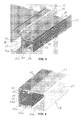
Fig. 3 is a schematic perspective view of the embodiment ofFig. 2 ; -
Fig. 4 is a schematic perspective view of a second embodiment of a control panel according to the invention; -
Fig. 5 is a schematic perspective view of a third embodiment of a control panel according to the invention; and -
Fig. 6 is a schematic perspective view of a fourth embodiment of a control panel according to the invention. - With reference to
Fig. 1 , a combined refrigerator and freezer appliance of the built-in type is generally designated with 10. The refrigerator unit is designated with 12 and comprises a refrigerated compartment 13 (Fig. 2 ) accessible via adoor 14. The freezer unit is designated with 16 and comprises a compartment 17 (Fig. 2 ) refrigerated at a lower temperature and accessible via adoor 18. Therefrigerator unit 12 is placed above thefreezer unit 16. A control panel generally designated with 20 is housed in the space betweendoor 14 anddoor 18 on the front of the appliance, and is fixed to themullion 21, as shown inFig. 2 . - With reference to
Fig. 2 , eachdoor walls 14c, 18c equipped with sealing means, as known in the field. - A built-in appliance is typically manufactured without external door panels 14a, 18a. These are typically provided by furniture manufacturers and applied onto the internal panels 14b, 18b when furniture and fittings are mounted and assembled in the kitchen or other environment of a house. The thickness of external door panels 14a, 18a varies depending on the type of panel and on the material of which the panel is made. Typical variance is of from 18 to 26 mm. Since the door structure comprises at least two panels and since the thickness of at least the external panels varies, a
recess 19 running horizontally betweendoors control panel 20 is housed in such recess. -
Control panel 20 comprises aplate 22 running horizontally inrecess 19 and fixed to themullion 21 of the appliance.Plate 22 is connected to aU-shaped element 24 comprising anupper leg 26 and alower leg 26a connected by an intermediatevertical portion 25.Legs vertical portion 25 supports visualization and/or control means housed inholes 28. The U-shapedelement 24 is oriented with the open side directed towardplate 22 and with the intermediatevertical portion 25 protruding forward. Such intermediate portion is to be substantially aligned with the external surface of external door plate 14a, 18a. The U-shapedelement 24 is adjustably mounted onplate 22 by fastening means extendable from the plate toward a user facing the appliance. - Referring also to
Fig. 3 ,plate 22 is formed with anupper bracket 30 and alower bracket 30a, parallel to each other and perpendicular toplate 22. The upper side ofupper bracket 30 and the lower side oflower bracket 30a are provided with a plurality of teeth 32, 32a extending transversally for at least a portion ofbracket plate 22. - Likewise, the lower side of
upper leg 26 of theU-shaped element 24 and the upper side oflower leg 26a are provided with a plurality ofteeth 36, 36a extending transversally for at least a portion oflegs teeth 36, 36a are arranged on a plurality of parallel rows in the central portion oflegs - The distance between
bracket legs teeth 36 and teeth 32a frictionally engage teeth 36a. The U-shapedelement 24 is designed and manufactured in such a way thatupper leg 26 andlower leg 26a are endowed with a certain degree of flexibility that allow for a sliding movement of the U-shapedelement 24 onbrackets teeth 36, 36a from teeth 32, 32a upon pulling in the direction of arrow B or pushing in the direction of arrow A (Fig. 2 ) with a force prevailing on the friction engagement of the teeth. When theU-shaped element 24 has been adjusted at a desired position,teeth 36, 36a are engaged again with teeth 32, 32a by discontinuing the pulling or pushing force. By this construction it is possible to both adjust the distance of the U-shapedelement 24 fromplate 22 and fasten it to plate 22 quickly and simply. When theU-shaped element 24 is adjusted in a position spaced apart fromplate 22, a slit is formed with respect toplate 22. To cover said slit anangle element 42 running along the entire U-shapedelement 24 is positioned at least on theupper leg 26 in abutment against plate (22). -
Fig. 2 andFig. 3 show schematically afinishing cover 40 mounted externally on the intermediatevertical portion 25 of theU-shaped element 24. Finishingcover 40 can be made of metal or glass and has the function to coverrecess 19 from sight of a user and improve the outer appearance of thecontrol panel 20. Visualization means such as one ormore display 41 are visible throughfinishing cover 40, as well ascontrol buttons 43. Both the visualization and control means are mounted inholes 28 ofvertical portion 25 of theU-shaped element 24, and are electrically connected to sensor means and control units not shown. -
Figs. 4 shows an embodiment of the control panel according to the invention in which the sliding movement of the U-shapedelement 24 is limited by pins 44, 44a projecting inwardly fromleg slits 45, 45a ofbrackets -
Figs. 5 shows an embodiment of the control panel according to the invention in which the sliding movement of the U-shapedelement 24 is limited by ascrew 50 housed in a through bore ofupper leg 26 with the stem extending downwardly intoslit 45 ofbracket 30. In this embodiment theupper leg 26 of the U-shapedelement 24 is formed with a groove 52 housing thehead 54 of thescrew 50.Angle element 42 is positioned on theupper leg 26 to cover groove 52 and screw 50. -
Figs. 6 shows an embodiment of the control panel according to the invention in which at least arod 62 projects outwardly from theplate 22 in the region withinbracket Rod 62 is provided withteeth 60 on its outer surface. TheU-shaped element 24 is also provided with at least ahollow cylinder 66 that projects inwardly from the intermediatevertical portion 25 of theU-shaped element 24. Thehollow cylinder 66 is provided with teeth orthreads 64 in the internal cavity. The relative position ofrod 62 andhollow cylinder 66 onplate 22 and on the intermediatevertical portion 25 of theU-shaped element 24, respectively, is such that they are aligned and thatrod 62 entershollow cylinder 66 by pushing theU-shaped element 24 againstplate 22. Insuch disposition teeth 60 frictionally engageteeth 64 so that theU-shaped element 24 can be adjustably fastened toplate 22. When fastening at a desired position is achieved, theangle element 42 is positioned on theupper leg 26 to cover any slit existing betweenupper leg 26 andplate 22. - It appears from the description above that the
control panel 20, possibly combined with finishingplate 40, can be aligned with the external door panels 14a, 18a by a simple movement of pulling/pushing it with respect to the fixedplate 22. - Therefore, such alignment can be done after the appliance is installed in its final location and possibly assembled with the furniture and fittings surrounding it. The result is an enhanced visibility and an easy access of the control panel by a user.
- It is clear from the description above that other embodiments of the adjustable fastening means of the control panel according to the invention are possible within the same inventive concept. In particular, teeth can be replaced by other means suitable to establish an adjustable fastening by friction engagement of parts.
Claims (14)
- Household appliance comprising at least a door (14; 18) providing access to an internal compartment (13; 17) and a control panel (20) mounted in the vicinity of said door (14; 16), characterized in that said control panel (20) comprises a first element (22) fixed to said appliance and a second element (24) supporting visualization and/or control means (41, 43) for said appliance, said second element (24) being adjustably mounted on said first element (22) whereby said second element (24) and said door (14;18) of said appliance can be aligned.
- Household appliance according to claim 1, wherein the first element comprises a plate (22) and the second element is a U-shaped element (24) comprising two parallel legs (26, 26a) disposed horizontally and an intermediate vertical portion (25), said U-shaped element (24) being oriented with the open side facing said plate (22) and being adjustably mounted on said plate (22) by fastening means (36, 36a; 62, 60) projecting from said plate (22) to frictionally engage corresponding means (32, 32a; 66, 64) projecting inwardly from said U-shaped element (24).
- Household appliance according to claim 1 or 2, comprising two doors (14, 18) providing access to two internal compartments (13, 17) located one above the other, characterized in that said control panel (20) runs horizontally in the space (19) between said two doors (14, 18), with said intermediate vertical portion (25) supporting said visualization and/or control means (41, 43) being substantially aligned with said two doors (14, 18).
- Household appliance according to any of the preceding claims, wherein said appliance is of the built-in type and said doors (14, 18) comprise external door panels (14a, 18a), characterized in that said intermediate vertical portion (25) supporting said visualization and/or control means (41, 43) is substantially aligned with said external door panels (14a, 18a) of said two doors (14, 18).
- Household appliance according to claim 2, characterized in that said plate (22) is formed with an upper bracket (30) and a lower bracket (30a) parallel to each other and projecting perpendicularly from plate (22), said brackets being provided with a plurality of teeth (32, 32a) operatively engaging corresponding teeth (36, 36a) extending from legs (26, 26a) of said U-shaped element (24).
- Household appliance according to claim 5, characterized in that said teeth (32) are formed on the upper side of said upper bracket (30) and said teeth (32a) are formed on the lower side of said lower bracket (30a), said plurality of teeth (32, 32a) extending transversally for at least a portion of said brackets (30, 30a).
- Household appliance according to claim 5, characterized in that said plurality of teeth (32, 32a) are arranged on a plurality of parallel rows extending from the front edge of said brackets (30, 30a) toward said plate (22).
- Household appliance according to claim 5, characterized in that said two parallel legs (26, 26a) of said U-shaped element comprise un upper leg (26) and a lower leg (26a), and said teeth (36, 36a) extending from said legs (26, 26a) of said U-shaped element (24) comprise teeth (36) provided on the he lower side of said upper leg (26) and teeth (36a) provided on the upper side of said lower leg (26a) of said U-shaped element (24).
- Household appliance according to claim 5, characterized in that said teeth (36, 36a) of said legs (26, 26a) of said U-shaped element (24) extend transversally for at least a portion of said legs (26, 26a).
- Household appliance according to claim 2, characterized in that said plate (22) is formed with an upper bracket (30) and a lower bracket (30a), parallel to each other and projecting perpendicularly from plate (22), with at least a rod (62) projecting from said plate in the region within said brackets (30, 30a), said rod (62) being provided with teeth (60) on its outer surface frictionally engaging corresponding teeth (64) of a hollow cylinder (66) that projects inwardly from said U-shaped element (24).
- Household appliance according to claim 10, characterized in that said teeth (64) of said hollow cylinder (66) are provided in the internal cavity thereof, said rod (62) and said hollow cylinder (66) being operatively aligned, whereby said rod (62) enters said hollow cylinder (66) by pushing said U-shaped element (24) against said plate (22).
- Household appliance according to claim 2, characterized in that a finishing plate (40) is fixed to the vertical portion (25) of said U-shaped element (24).
- Household appliance according to claim 2, characterized in that an angle element (42) is positioned at least on the upper leg (26) of said U-shaped element (24) in abutment against said plate (22) to cover the space defined between said plate (22) and said U-shaped element (24).
- Household appliance according to any preceding claim, characterized in that said two internal compartments (13, 17) are refrigerated compartments of a refrigerator (12) and of a freezer (16) units.
Priority Applications (1)
| Application Number | Priority Date | Filing Date | Title |
|---|---|---|---|
| EP08102010A EP2096393A1 (en) | 2008-02-26 | 2008-02-26 | Built-in household appliance with adjustable control panel |
Applications Claiming Priority (1)
| Application Number | Priority Date | Filing Date | Title |
|---|---|---|---|
| EP08102010A EP2096393A1 (en) | 2008-02-26 | 2008-02-26 | Built-in household appliance with adjustable control panel |
Publications (1)
| Publication Number | Publication Date |
|---|---|
| EP2096393A1 true EP2096393A1 (en) | 2009-09-02 |
Family
ID=39691160
Family Applications (1)
| Application Number | Title | Priority Date | Filing Date |
|---|---|---|---|
| EP08102010A Withdrawn EP2096393A1 (en) | 2008-02-26 | 2008-02-26 | Built-in household appliance with adjustable control panel |
Country Status (1)
| Country | Link |
|---|---|
| EP (1) | EP2096393A1 (en) |
Cited By (1)
| Publication number | Priority date | Publication date | Assignee | Title |
|---|---|---|---|---|
| US9980581B2 (en) | 2012-09-24 | 2018-05-29 | Carrier Corporation | Refrigerated sales cabinet |
Citations (5)
| Publication number | Priority date | Publication date | Assignee | Title |
|---|---|---|---|---|
| EP0102413A2 (en) * | 1981-10-16 | 1984-03-14 | SMEG S.p.A. | Domestic apparatus with a front panel moving backward for access to control and handling devices |
| JP2001324258A (en) * | 2000-05-16 | 2001-11-22 | Sanyo Electric Co Ltd | Refrigerator |
| FR2889734A1 (en) * | 2005-08-11 | 2007-02-16 | Whirlpool Co | REFRIGERATION APPARATUS WITH DISTRIBUTOR CONTAINED IN AN INTEGRATED CENTRAL RAIL |
| DE202007003428U1 (en) | 2007-03-07 | 2007-05-03 | BSH Bosch und Siemens Hausgeräte GmbH | Cooling device e.g. refrigerator, has user interface that is arranged at one door and comprising temperature display devices with number of units that are arranged in row and are switchable between different states |
| DE202007006099U1 (en) * | 2006-08-24 | 2007-12-27 | Liebherr-Hausgeräte Ochsenhausen GmbH | Fridge and / or freezer |
-
2008
- 2008-02-26 EP EP08102010A patent/EP2096393A1/en not_active Withdrawn
Patent Citations (5)
| Publication number | Priority date | Publication date | Assignee | Title |
|---|---|---|---|---|
| EP0102413A2 (en) * | 1981-10-16 | 1984-03-14 | SMEG S.p.A. | Domestic apparatus with a front panel moving backward for access to control and handling devices |
| JP2001324258A (en) * | 2000-05-16 | 2001-11-22 | Sanyo Electric Co Ltd | Refrigerator |
| FR2889734A1 (en) * | 2005-08-11 | 2007-02-16 | Whirlpool Co | REFRIGERATION APPARATUS WITH DISTRIBUTOR CONTAINED IN AN INTEGRATED CENTRAL RAIL |
| DE202007006099U1 (en) * | 2006-08-24 | 2007-12-27 | Liebherr-Hausgeräte Ochsenhausen GmbH | Fridge and / or freezer |
| DE202007003428U1 (en) | 2007-03-07 | 2007-05-03 | BSH Bosch und Siemens Hausgeräte GmbH | Cooling device e.g. refrigerator, has user interface that is arranged at one door and comprising temperature display devices with number of units that are arranged in row and are switchable between different states |
Cited By (2)
| Publication number | Priority date | Publication date | Assignee | Title |
|---|---|---|---|---|
| US9980581B2 (en) | 2012-09-24 | 2018-05-29 | Carrier Corporation | Refrigerated sales cabinet |
| US10285512B2 (en) | 2012-09-24 | 2019-05-14 | Carrier Corporation | Refrigerated sales cabinet |
Similar Documents
| Publication | Publication Date | Title |
|---|---|---|
| US7770985B2 (en) | Kitchen appliance having floating glass panel | |
| US8783801B2 (en) | Household appliance | |
| EP2225510B1 (en) | Refrigerator | |
| US12446120B2 (en) | Mounting arrangement for over-the-range cooking appliance | |
| US10400491B2 (en) | Hinge cover with door stop | |
| US9482437B2 (en) | Front frame for a cooking device | |
| EP2146615B1 (en) | Under-counter mounting system for a dishwasher, and associated method | |
| RU2413910C2 (en) | Door for domestic appliance | |
| CN211424841U (en) | Household appliances with appliance parts with inclined strip surfaces and functional elements arranged thereon | |
| CN107270636B (en) | Door shelf with base body and additional parts for a domestic refrigeration device, and domestic refrigeration device | |
| US9151536B2 (en) | Refrigeration device comprising a dispensing device | |
| US20190125078A1 (en) | Mounting device and domestic appliance | |
| JP6426671B2 (en) | System kitchen | |
| EP2933567B1 (en) | Household cooking appliance | |
| CA2803596C (en) | Domestic cooking appliance having side wall trim mounting | |
| GB2513992A (en) | Method of installing domestic appliances to be one above the other | |
| RU2463937C2 (en) | Household refrigerating device | |
| EP4105577A1 (en) | Built-in refrigerator | |
| KR101478359B1 (en) | Built-in type refrigerator | |
| KR200300295Y1 (en) | Fixing Structure decoration for Door Handle of Kim-Chi Storage | |
| RU2428909C2 (en) | Furniture structure for inbuilt devices | |
| WO2006059303A2 (en) | A cooking appliance | |
| KR200437508Y1 (en) | Screen structure of system furniture | |
| KR200295377Y1 (en) | Having improve doornob structure of Kimchi refrigerator | |
| KR100666496B1 (en) | Display Panel Fastening Structure of Kimchi Refrigerator |
Legal Events
| Date | Code | Title | Description |
|---|---|---|---|
| PUAI | Public reference made under article 153(3) epc to a published international application that has entered the european phase |
Free format text: ORIGINAL CODE: 0009012 |
|
| AK | Designated contracting states |
Kind code of ref document: A1 Designated state(s): AT BE BG CH CY CZ DE DK EE ES FI FR GB GR HR HU IE IS IT LI LT LU LV MC MT NL NO PL PT RO SE SI SK TR |
|
| AX | Request for extension of the european patent |
Extension state: AL BA MK RS |
|
| 17P | Request for examination filed |
Effective date: 20100216 |
|
| 17Q | First examination report despatched |
Effective date: 20100317 |
|
| AKX | Designation fees paid |
Designated state(s): DE ES FR GB IT |
|
| STAA | Information on the status of an ep patent application or granted ep patent |
Free format text: STATUS: THE APPLICATION IS DEEMED TO BE WITHDRAWN |
|
| 18D | Application deemed to be withdrawn |
Effective date: 20170901 |