EP2096383B1 - Method for controlling an ice making assembly for a refrigerator - Google Patents
Method for controlling an ice making assembly for a refrigerator Download PDFInfo
- Publication number
- EP2096383B1 EP2096383B1 EP09002688.1A EP09002688A EP2096383B1 EP 2096383 B1 EP2096383 B1 EP 2096383B1 EP 09002688 A EP09002688 A EP 09002688A EP 2096383 B1 EP2096383 B1 EP 2096383B1
- Authority
- EP
- European Patent Office
- Prior art keywords
- water
- ice
- tray
- rods
- electrodes
- Prior art date
- Legal status (The legal status is an assumption and is not a legal conclusion. Google has not performed a legal analysis and makes no representation as to the accuracy of the status listed.)
- Active
Links
Images


Classifications
-
- F—MECHANICAL ENGINEERING; LIGHTING; HEATING; WEAPONS; BLASTING
- F25—REFRIGERATION OR COOLING; COMBINED HEATING AND REFRIGERATION SYSTEMS; HEAT PUMP SYSTEMS; MANUFACTURE OR STORAGE OF ICE; LIQUEFACTION SOLIDIFICATION OF GASES
- F25C—PRODUCING, WORKING OR HANDLING ICE
- F25C1/00—Producing ice
- F25C1/08—Producing ice by immersing freezing chambers, cylindrical bodies or plates into water
-
- F—MECHANICAL ENGINEERING; LIGHTING; HEATING; WEAPONS; BLASTING
- F25—REFRIGERATION OR COOLING; COMBINED HEATING AND REFRIGERATION SYSTEMS; HEAT PUMP SYSTEMS; MANUFACTURE OR STORAGE OF ICE; LIQUEFACTION SOLIDIFICATION OF GASES
- F25C—PRODUCING, WORKING OR HANDLING ICE
- F25C5/00—Working or handling ice
- F25C5/02—Apparatus for disintegrating, removing or harvesting ice
- F25C5/04—Apparatus for disintegrating, removing or harvesting ice without the use of saws
- F25C5/08—Apparatus for disintegrating, removing or harvesting ice without the use of saws by heating bodies in contact with the ice
-
- F—MECHANICAL ENGINEERING; LIGHTING; HEATING; WEAPONS; BLASTING
- F25—REFRIGERATION OR COOLING; COMBINED HEATING AND REFRIGERATION SYSTEMS; HEAT PUMP SYSTEMS; MANUFACTURE OR STORAGE OF ICE; LIQUEFACTION SOLIDIFICATION OF GASES
- F25C—PRODUCING, WORKING OR HANDLING ICE
- F25C2600/00—Control issues
- F25C2600/04—Control means
-
- F—MECHANICAL ENGINEERING; LIGHTING; HEATING; WEAPONS; BLASTING
- F25—REFRIGERATION OR COOLING; COMBINED HEATING AND REFRIGERATION SYSTEMS; HEAT PUMP SYSTEMS; MANUFACTURE OR STORAGE OF ICE; LIQUEFACTION SOLIDIFICATION OF GASES
- F25C—PRODUCING, WORKING OR HANDLING ICE
- F25C2700/00—Sensing or detecting of parameters; Sensors therefor
- F25C2700/04—Level of water
Definitions
- the present disclosure relates to a method for controlling an ice making assembly for a refrigerator.
- Refrigerators are domestic appliances used for storing foods in a refrigerated or frozen state.
- refrigerators include: a side-by-side type refrigerator in which a refrigerator compartment and a freezer compartment are disposed in the left and right sides; a bottom-freezer type refrigerator in which a refrigerator compartment is disposed above a freezer compartment; and a top-mount type refrigerator in which a refrigerator compartment is disposed under a freezer compartment.
- refrigerators have a structure that allows a user to access food or drink disposed inside a refrigerator compartment through an alternate access point without having to open a primary refrigerator compartment door.
- a compressor, a condenser, and an expansion member are disposed inside a refrigerator, and an evaporator is disposed on the backside of a refrigerator main body, as refrigeration-cycle components of the refrigerator.
- an ice making assembly can be provided inside the refrigerator.
- the ice making assembly may be mounted in a freezer compartment, a refrigerator compartment, a freezer compartment door, or a refrigerator compartment door.
- an additional water tank is disposed at a predetermined side of a refrigerator and is connected to an ice making tray through a tube to supply water to the ice making tray, or a tap of an external water source is directly connected to the ice making tray through a tube.
- the ice maker comprises a tray, which is filled with water and which is reciprocatively moving relative to fingers. Due to the dipping motion of the fingers produced by the reciprocating moving of the tray, smooth ice bodies with a crystal clear appearance are produced.
- an opening is provided through a cover at a rear inner corner thereof communicating with a similar opening in a lower plenum housing positioned above the tray.
- An output block operates a fill valve used for filling the tray. For filling the tray, the fill valve output is energized to open a solenoid valve and to fill the tray with a volume of water. A fixed quantity of water is added to the tray in a filling operation.
- a supply of water is automatically interrupted for preventing overflow when the water supplied to an ice making tray reaches a set level, and a method for controlling the ice making assembly.
- the amount of supplied water can be maintained at a constant level regardless of water pressure variations occurring at the location the ice-making assembly is installed, and a method for controlling the ice making assembly.
- unnecessary power consumption can be reduced by immediately detecting a water supply error when water is not supplied to an ice making tray due to, for example, malfunctioning of a water supply valve, and a method for controlling the ice making assembly.
- an ice making assembly for a refrigerator, the ice making assembly including: a tray comprising a water supply part and a plurality of ice recesses; a plurality of fins above the tray; a plurality of rods inserted in the ice recesses through the fins and configured to be lifted and titled together with the fins after a freezing operation; and a water level sensor at one of the ice recesses.
- water can be supplied at a constant level for each ice making cycle regardless of water pressure variations at the installed location of the refrigerator. Therefore, water supply overflow, freezing of overflowed water in the refrigerator, and leakage of overflowed water from the refrigerator can be prevented.
- water can be supplied to the ice recesses at an equal level.
- the ice making assembly can detect the level of water using existing components without the need for an additional device. This reduces the manufacturing costs of the ice making assembly.
- an ice making assembly is mounted at a freezer compartment door.
- the ice making assembly can be mounted at other places such as a freezer compartment, a refrigerator compartment, and a refrigerator compartment door without departing from the scope of the invention.
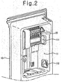
- FIGs. 1 and 2 are perspective views illustrating an ice making assembly structure for a refrigerator according to an exemplary embodiment of the invention.
- an ice making assembly 20 may be mounted on the backside of a door 10, and the backside of the door 10 may be recessed to form an ice making space 11 for accommodating the ice making assembly 20.
- a cooling air supply hole 111 may be formed at a side of the ice making space 11 for allowing inflow of cooling air from an evaporator (not shown), and a cooling air discharge hole 112 may be formed in the side of the ice making space 11 to allow the cooling air from the ice making space 11 to flow back the evaporator.
- the ice making assembly 20 may be mounted at an upper portion of the ice making space 11, and a container 30 may be mounted under the ice making assembly 20 to store ice made by the ice making assembly 20.
- the ice making assembly 20 may be protected by an ice making cover 31.
- the ice making cover 31 may also provide guidance for the ice separated from the ice making assembly 20 so that it follows a path directly to the container 30.
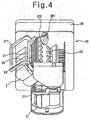
- FIG. 3 is a perspective view illustrating the ice making assembly 20 according to an embodiment of the invention
- FIG. 4 is a perspective view illustrating the ice making assembly 20, according to an embodiment of the invention, just before ice is transferred to the container 30.
- the ice making assembly 20 of the current embodiment may include: a tray 21 having a plurality of ice recesses 211 for making ice in a predetermined shape; a plurality of fins 24 stacked above the tray 21 and capable of vertical and rotational movement; a plurality of rods 23 configured to be inserted into the ice recesses 211 through the fins 24; an ice ejecting heater 25 provided at the lowermost of the plurality of fins 24; a supporting plate 27 configured to support the ice ejecting heater 25, the remainder of the plurality of fins 24, and the rods 23 as one unit; a water supply part 26 disposed at an end of the tray 21; and a control box 28 disposed at another other end of the tray 21.
- a heater (not shown) may be mounted at the bottom of the tray 21 to maintain the temperature of the tray 21 at a temperature above freezing.
- a supporting lever 271 may extend from a front end of the supporting plate 27, and a hinge 272 may be disposed at an end of the supporting plate 27.
- ice cubes (I) having a shape corresponding to the shape of the ice recesses 211 may be formed around the rods 23.
- a cam 29 and a driving motor may be disposed inside the control box 28.
- the driving motor may drive a rotational movement of the cam 29.
- the hinge 272 is coupled to the cam 29 so that the hinge 272 can be used and rotated by rotating the cam 29.
- the ice ejecting heater 25 may have a plate-like shape and may contact the rods 23. Alternatively, the ice ejecting heater 25 may be embedded within the rods 23.
- the supporting plate 27 may act to close an open-top of the tray 21 ( FIG. 3 ) such that water supplied to the tray 21 is indirectly cooled by cooling air supplied to the ice making space 11 and flowing about the fins 24 and rods 23.
- the heater attached to the tray 21 may be operated to maintain the tray 21 at a temperature higher than 0°C, to create an environment that can make transparent ice in the ice making assembly 20.
- the tray 21 may be maintained at a temperature above freezing so that the water freezes slowly, starting at the freezing rod 23. The air in the water is then able to escape before the water is completely frozen. Thus, transparent ice, which is preferred by the user, may be produced.
- the rods 23 may be inserted into the ice recesses 211 of the tray 21, and a freezing operation may be started.
- the freezing operation may be started after a predefined volume of water is added to the tray 21.
- the freezing operation may be started by supplying cooling air to the ice making space 11.
- the temperature of the fins 24 may then be reduced to below the freezing temperature by conduction heat transfer with the supplied cooling air.
- the temperature of the rods 23 may also be reduced to below the freezing temperature by conduction heat transfer with the fins 24.
- Portions of the rods 23 inserted in the ice recesses 211 are submerged in the water. Therefore, the water is gradually frozen starting from a region closest to the rods 23. As the water freezes, the frozen region becomes attached to the rods 23. The freezing of the water then proceeds outwardly from the outer surfaces of the rods 23 to the inner surfaces of the ice recesses 211.
- the cam 29 may be rotated to move the rods 23, and the ice cubes formed thereon, out of the ice recesses 211. That is, the cam 29 is rotated to lift the rods 23 vertically upward, thus the formed ice cubes (I) may be completely removed from the ice recesses 211.
- the cam 29 may be further rotated to tilt the rods 23 to a predetermined angle.
- the completion of the freezing of the water may be determined by the passage of a predetermined amount of time. More specifically, if a predetermined time passes after the start of the freezing of the water, this may determine that the freezing is competed.
- Another method of determining the completion of freezing involves lifting rods 23, via cam 29, to a predetermined height after a predetermined time from the start of freezing.
- the predetermined height may be a height at which ice attached to the rods 23 is not yet fully separated from the ice recesses 211.
- the amount of water remaining in the ice recesses may be detected.
- the amount of water remaining in the ice recesses 211 may be detected using a water level sensor mounted on the tray 21. If the amount of water remaining in the ice recesses 211 is equal to or less than a predetermined amount, it may be determined that the freezing is completed.
- the rods 23 may be moved down to their original positions to continue the freezing of the water.
- the cam 29 may be rotated such that it moves the rods 23 vertically upward out of the ice recesses 211.
- the cam 29 is further rotated to effect rotation of the rods 23. More specifically, the hinge 272 is rotated by the cam 29 to rotate the rods 23 to a predetermined angle.
- the ice ejecting heater 25 may be operated.
- the ice ejecting heater 25 When the ice ejecting heater 25 is operated, the temperature of the rods 23 increases, and thus the ice cubes (I) are separated from the rods 23. The separated ice cubes (I) may then fall into the container 30.
- FIG. 5 is a perspective view illustrating the tray 21 of the ice making assembly 20 according to an embodiment of the invention.
- the ice recesses 211 may be arranged in the tray 21 of the ice making assembly 20. Channels 213 having a predetermined depth may be formed between the ice recesses 211.
- Water can travel between neighboring ice recesses 211 through the channels 213. Bottoms of the channels 213 are spaced apart from bottoms of the ice recesses 211.
- a guide 212 may be formed at an end portion of the tray 21 to guide water supplied from the water supply part 26 to the tray 21 and to the ice recesses 211. Water may be supplied to the ice recesses 211 closest to the guide 212 and may gradually travels to the ice recess 211 farthest from the guide 212.
- a water level sensor 40 may be mounted at a side of the ice recess 211 farthest from the guide 212, e.g., at a side of the ice recess located at an end of the tray 21 opposite to the guide 212. Further, a temperature sensor 50 may be mounted at a side of the tray 21 and may be used in conjunction with a subassembly to maintain the tray 21 at a constant temperature.
- a tray heater (not shown) may be installed at the tray 21. The tray heater may be installed at the tray 21 in an embedded manner or attached manner.
- FIG. 6 is a perspective view illustrating the water level sensor 40 of the ice making assembly 20 according to an embodiment of the invention.
- the water level sensor 40 provided at the ice making assembly 20 may be mounted at the side of the ice recess 211 as described above.
- the water level sensor 40 is a capacitive sensor capable of detecting the existence of an object by sensing the capacitance of the object using multiple electrodes disposed at a side of the object.
- the capacitance water level sensor 40 is a more reliable method of detecting water levels as it is not subject to instantaneous, temporary water level changes, for example caused by opening and closing the refrigerator door housing the ice making device.
- the water level sensor 40 includes a plurality of electrodes, and output terminals 41.
- the output terminals 41 may extend from the electrodes and may connect to the control unit 45, which may be a control unit for operation of the refrigerator in general.
- the plurality of electrodes are covered with a waterproof layer 42 ( FIGs. 6 and 7 ) so that water cannot function as a conductor having resistance between the electrodes.
- a waterproof layer 42 FIGs. 6 and 7
- the water level sensor 40 includes an upper electrode A, a middle electrode B, and a lower electrode C.
- the electrode A When the water level sensor 40 is attached to the tray 21, the electrode A may be located at a position slightly lower than the highest water level of the ice recess 211, and the electrode C may be located at a position higher than the bottom of the ice recess 211.
- the electrode C may be located at the same height as the bottom of the channel 213, which is the channel through which water can flow from one ice recess to a neighboring ice recess.
- the electrodes A, B, and C cannot make direct contact with water due to the waterproof layer 42.
- Electrode C is grounded, and an electric charge can be stored between the electrodes B and C or the electrodes A and C according to the level of water.
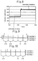
- FIG. 7 is a sectional view taken along line I-I' of FIG. 5 for illustrating the increasing level of water supplied to the tray of the ice making assembly according to an embodiment of the invention
- FIG. 8 is a graph illustrating variations of circuit capacitance with respect to the level of water in the ice making assembly of FIG. 7 .
- the capacitance between the electrodes B and C changes. That is, the capacitance between the electrodes B and C changes from the capacitance Ca of air to the capacitance (Cw) of water. Accordingly, a sensor signal is sent to the control unit 45 through the output terminal 41 of the electrode B.
- the control unit 45 detects the variation of the capacitance and determines that the level of water has reached the height of the electrode B.
- the capacitance between electrodes A and C will change, similar to the change described above with respect to electrodes B and C. That is, the medium between electrodes A and C changes from air to water, and thus the capacitance between electrodes A and C changes.
- a sensor signal corresponding to the capacitance change is sent to the control unit 45 through the output terminal 41 (connected to the electrode A). The control unit 45 thus may determine that the level of water has reached the height of electrode A.
- FIGs. 9 to 12 illustrate water level variations of the tray 21 of the ice making assembly 20 when water is supplied to the tray 21.
- rods 23 are not depicted in FIGs. 9 to 12 . It will be understood, depending on whether water is added before or after rods 23 are inserted into the ice recesses 211, that the displacement of water attributable to the rods 23 may be considered in determining the positioning of electrodes A, B, and C.
- the level of water in the tray 21 at a side of the tray 21 adjacent the guide 212 is different from a water level at a side of the tray 21 opposite to the guide 212.
- water is first filled in the ice recess 211A closest to the guide 212.
- the level of water in the closest ice recess 211A exceeds the bottom of the channel 213, the supplied water then travels to the adjacent ice recess 211B.
- a large amount of water is not transferred to the neighboring ice recesses all at once due to the narrow width of the channel 213 and the surface tension of the water. Therefore, at the beginning of the water supply, the level of water in the ice recess 211A closest to the guide 212 is considerably different from the level of water in the ice recess 211C, which is where the water level sensor 40 is installed.
- the ice recess 211C maybe the ice recess farthest from the guide 212.
- the water supply is temporarily interrupted.
- the water level is then stabilized at a level (c) for a predetermined time.
- the stabilized water level (c) is higher than the height of the electrode B yet lower than the height of electrode A.
- the predetermined amount of time that the water supply is stopped may be adjusted according to the pressure of water and the size of the channel 213.
- the level of water changes to result in a water level difference h2 between ice recess 211 A, closest to guide 212, and ice recess 211C, farthest from guide 212.
- the water level difference h2 is not as large as the initial water level difference h1 because water is re-supplied after the level of water has increased to some degree. That is, since the intermediate water level h1 is somewhat higher than the bottom of the channel 213, the water travels between all ice recesses, 211A through 211C, more smoothly than it did in the earlier stage of water supply. In addition, the influence of surface tension of water is less as compared with the earlier stage of water supply.
- the increasing water level is detected at the electrode A. Then, the supply of water is suspended again to stabilize the water level.
- the stabilized final water level (d) is higher than the height of the electrode A.
- At least two electrodes may be used to detect a capacitance variation between the two electrodes and suspend a supply of water at an intermediate water level.
- the water supply suspending time may be shortened or extended depending to the position of the electrode B.
- the spacing between electrodes C and B appears to be equal to the spacing between electrodes A and B; however, the spacing need not be equal. It is within the scope of the invention to adjust the position of, and spacing between, electrodes A, B, and C.
- the electrodes may thus be spaced apart at regular or irregular intervals.
- the amount of water remaining after an ice making operation is complete is determined by the position of electrode B. More specifically, according to an embodiment of the present disclosure, the rod 23 may be slightly lifted after a predetermined amount of time has passed from the start of an ice making operation so as to detect the amount of remaining water. If the amount of remaining water is equal to or smaller than a set amount, it is determined that ice is completely made, and the ice is ejected. If the amount of remaining water is greater than the set amount, the rod 23 is moved down to continue the ice making operation.
- the amount of remaining water is determined by the position of the electrode B. If the level of water in the ice recesses 211 is lower than the height of the electrode B, the control unit 45 will determine that there is no water in the ice recess 211, because the control unit 45 cannot detect a capacitance variation. That is, as the position of the electrode B becomes lower, the amount of remaining water will be reduced, and as the amount of remaining water is reduced, the size of ice pieces will increase.
- the capacitive sensor 40 capable of sensing capacitance variations, the level of water can be precisely detected, and by supplying water in multiple steps, overflowing of supplied water can be prevented.
Description
- The present disclosure relates to a method for controlling an ice making assembly for a refrigerator.
- Refrigerators are domestic appliances used for storing foods in a refrigerated or frozen state.
- Recently, various kinds of refrigerators have been introduced into the market. Examples of recent refrigerators include: a side-by-side type refrigerator in which a refrigerator compartment and a freezer compartment are disposed in the left and right sides; a bottom-freezer type refrigerator in which a refrigerator compartment is disposed above a freezer compartment; and a top-mount type refrigerator in which a refrigerator compartment is disposed under a freezer compartment.
- Furthermore, many of recently introduced refrigerators have a structure that allows a user to access food or drink disposed inside a refrigerator compartment through an alternate access point without having to open a primary refrigerator compartment door. A compressor, a condenser, and an expansion member are disposed inside a refrigerator, and an evaporator is disposed on the backside of a refrigerator main body, as refrigeration-cycle components of the refrigerator.
- In addition, an ice making assembly can be provided inside the refrigerator. The ice making assembly may be mounted in a freezer compartment, a refrigerator compartment, a freezer compartment door, or a refrigerator compartment door.
- To satisfy consumers' increasing demands for transparent ice, much research has been conducted on ice making assemblies that can provide transparent ice.
- In an ice making assembly of the related art, an additional water tank is disposed at a predetermined side of a refrigerator and is connected to an ice making tray through a tube to supply water to the ice making tray, or a tap of an external water source is directly connected to the ice making tray through a tube.
-
US 5,187,948 describes a clear cube ice maker. Herein, the ice maker comprises a tray, which is filled with water and which is reciprocatively moving relative to fingers. Due to the dipping motion of the fingers produced by the reciprocating moving of the tray, smooth ice bodies with a crystal clear appearance are produced. In order to fill the tray with water, an opening is provided through a cover at a rear inner corner thereof communicating with a similar opening in a lower plenum housing positioned above the tray. An output block operates a fill valve used for filling the tray. For filling the tray, the fill valve output is energized to open a solenoid valve and to fill the tray with a volume of water. A fixed quantity of water is added to the tray in a filling operation. - It is an object of the present invention to provide a method for controlling an ice making assembly for a refrigerator, which can produce transparent ice easily and maintain the amount of water supplied to make ice at a constant level for each ice making cycle.
- This object is solved by a method according to claim 1. Further advantages, refinements and embodiments of the invention are described in the respective sub-claims.
- According to the present invention a supply of water is automatically interrupted for preventing overflow when the water supplied to an ice making tray reaches a set level, and a method for controlling the ice making assembly.
- According to the present invention, the amount of supplied water can be maintained at a constant level regardless of water pressure variations occurring at the location the ice-making assembly is installed, and a method for controlling the ice making assembly.
- According to the present invention, unnecessary power consumption can be reduced by immediately detecting a water supply error when water is not supplied to an ice making tray due to, for example, malfunctioning of a water supply valve, and a method for controlling the ice making assembly.
- There is provided an ice making assembly for a refrigerator and a method for controlling the ice making assembly as follows.
- According to the present invention, there is provided an ice making assembly for a refrigerator, the ice making assembly including: a tray comprising a water supply part and a plurality of ice recesses; a plurality of fins above the tray; a plurality of rods inserted in the ice recesses through the fins and configured to be lifted and titled together with the fins after a freezing operation; and a water level sensor at one of the ice recesses.
- By using the ice making assembly for a refrigerator and the method of controlling the ice making assembly according to the present invention, transparent ice can be easily made.
- Furthermore, water can be supplied at a constant level for each ice making cycle regardless of water pressure variations at the installed location of the refrigerator. Therefore, water supply overflow, freezing of overflowed water in the refrigerator, and leakage of overflowed water from the refrigerator can be prevented.
- Furthermore, although different amounts of water remain in the ice recesses of the tray, water can be supplied to the ice recesses at an equal level.
- Moreover, when water is not supplied to the tray due to malfunctioning of a water supply valve, such a situation can be immediately detected for reducing unnecessary power consumption.
- In addition, the ice making assembly can detect the level of water using existing components without the need for an additional device. This reduces the manufacturing costs of the ice making assembly.
- The details of one or more embodiments are set forth in the accompanying drawings and the description below. Other features will be apparent from the description and drawings, and from the claims.
-
-
FIGs. 1 and2 are perspective views illustrating an ice making assembly structure for a refrigerator according to an embodiment of the invention. -
FIG. 3 is a perspective view illustrating an ice making assembly according to an embodiment of the invention. -
FIG. 4 is a perspective view illustrating the ice making assembly, according to an embodiment of the invention, just before ice is transferred to a container. -
FIG. 5 is a perspective view illustrating a tray of the ice making assembly according to an embodiment of the invention. -
FIG. 6 is a perspective view illustrating a water level sensor of the ice making assembly according to an embodiment of the invention. -
FIG. 7 is a sectional view taken along line I-I' ofFIG. 5 for illustrating the increasing level of water supplied to the tray of the ice making assembly according to an embodiment of the invention. -
FIG. 8 is a graph illustrating variations of circuit capacitance with respect to the level of water in the ice making assembly ofFIG. 7 . -
FIGs. 9 to 12 are views for illustrating variations of the level of water supplied to the tray of the ice making assembly according to an embodiment of the invention. - Hereinafter, an ice making assembly for a refrigerator will be described in detail according to the disclosed exemplary embodiments of the present disclosure with reference to the accompanying drawings.
- In the following description, an ice making assembly is mounted at a freezer compartment door. However, the ice making assembly can be mounted at other places such as a freezer compartment, a refrigerator compartment, and a refrigerator compartment door without departing from the scope of the invention.
-
FIGs. 1 and2 are perspective views illustrating an ice making assembly structure for a refrigerator according to an exemplary embodiment of the invention. - Referring to
FIGs. 1 and2 , anice making assembly 20 may be mounted on the backside of adoor 10, and the backside of thedoor 10 may be recessed to form an ice making space 11 for accommodating theice making assembly 20. A coolingair supply hole 111 may be formed at a side of the ice making space 11 for allowing inflow of cooling air from an evaporator (not shown), and a coolingair discharge hole 112 may be formed in the side of the ice making space 11 to allow the cooling air from the ice making space 11 to flow back the evaporator. - In detail, the
ice making assembly 20 may be mounted at an upper portion of the ice making space 11, and acontainer 30 may be mounted under theice making assembly 20 to store ice made by theice making assembly 20. Theice making assembly 20 may be protected by anice making cover 31. Theice making cover 31 may also provide guidance for the ice separated from theice making assembly 20 so that it follows a path directly to thecontainer 30. -
FIG. 3 is a perspective view illustrating theice making assembly 20 according to an embodiment of the invention, andFIG. 4 is a perspective view illustrating theice making assembly 20, according to an embodiment of the invention, just before ice is transferred to thecontainer 30. - Referring to
FIGs. 3 and4 , theice making assembly 20 of the current embodiment may include: atray 21 having a plurality ofice recesses 211 for making ice in a predetermined shape; a plurality offins 24 stacked above thetray 21 and capable of vertical and rotational movement; a plurality ofrods 23 configured to be inserted into theice recesses 211 through thefins 24; anice ejecting heater 25 provided at the lowermost of the plurality offins 24; a supportingplate 27 configured to support theice ejecting heater 25, the remainder of the plurality offins 24, and therods 23 as one unit; awater supply part 26 disposed at an end of thetray 21; and acontrol box 28 disposed at another other end of thetray 21. - A heater (not shown) may be mounted at the bottom of the
tray 21 to maintain the temperature of thetray 21 at a temperature above freezing. A supportinglever 271 may extend from a front end of the supportingplate 27, and ahinge 272 may be disposed at an end of the supportingplate 27. During an ice making operation, as shown inFIG. 4 , ice cubes (I) having a shape corresponding to the shape of theice recesses 211 may be formed around therods 23. - A
cam 29 and a driving motor may be disposed inside thecontrol box 28. The driving motor may drive a rotational movement of thecam 29. Thehinge 272 is coupled to thecam 29 so that thehinge 272 can be used and rotated by rotating thecam 29. Theice ejecting heater 25 may have a plate-like shape and may contact therods 23. Alternatively, theice ejecting heater 25 may be embedded within therods 23. The supportingplate 27 may act to close an open-top of the tray 21 (FIG. 3 ) such that water supplied to thetray 21 is indirectly cooled by cooling air supplied to the ice making space 11 and flowing about thefins 24 androds 23. - Hereinafter, ice making and ice ejecting operations of the
ice making assembly 20 will be described. - First, the heater attached to the
tray 21 may be operated to maintain thetray 21 at a temperature higher than 0°C, to create an environment that can make transparent ice in theice making assembly 20. - When water is rapidly frozen by cooling air supplied from an evaporator, air dissolved in the water cannot escape from the water before it is frozen. Thus, when water is frozen together with the gas that is trapped inside the water, the resulting ice is not transparent.
- However, in the
ice making assembly 20 of the disclosed exemplary embodiments, thetray 21 may be maintained at a temperature above freezing so that the water freezes slowly, starting at the freezingrod 23. The air in the water is then able to escape before the water is completely frozen. Thus, transparent ice, which is preferred by the user, may be produced. - According to one embodiment, either before or after water is supplied to the
tray 21, therods 23 may be inserted into the ice recesses 211 of thetray 21, and a freezing operation may be started. In general, the freezing operation may be started after a predefined volume of water is added to thetray 21. The freezing operation may be started by supplying cooling air to the ice making space 11. The temperature of thefins 24 may then be reduced to below the freezing temperature by conduction heat transfer with the supplied cooling air. The temperature of therods 23 may also be reduced to below the freezing temperature by conduction heat transfer with thefins 24. Portions of therods 23 inserted in the ice recesses 211 are submerged in the water. Therefore, the water is gradually frozen starting from a region closest to therods 23. As the water freezes, the frozen region becomes attached to therods 23. The freezing of the water then proceeds outwardly from the outer surfaces of therods 23 to the inner surfaces of the ice recesses 211. - After the freezing of the water is completed, the
cam 29 may be rotated to move therods 23, and the ice cubes formed thereon, out of the ice recesses 211. That is, thecam 29 is rotated to lift therods 23 vertically upward, thus the formed ice cubes (I) may be completely removed from the ice recesses 211. Thecam 29 may be further rotated to tilt therods 23 to a predetermined angle. - The completion of the freezing of the water may be determined by the passage of a predetermined amount of time. More specifically, if a predetermined time passes after the start of the freezing of the water, this may determine that the freezing is competed.
- Another method of determining the completion of freezing, involves lifting
rods 23, viacam 29, to a predetermined height after a predetermined time from the start of freezing. The predetermined height may be a height at which ice attached to therods 23 is not yet fully separated from the ice recesses 211. Once therods 23 are lifted, the amount of water remaining in the ice recesses may be detected. In one embodiment, the amount of water remaining in the ice recesses 211 may be detected using a water level sensor mounted on thetray 21. If the amount of water remaining in the ice recesses 211 is equal to or less than a predetermined amount, it may be determined that the freezing is completed. On the other hand, if the amount of water remaining in the ice recesses 211 is greater than the predetermined amount, therods 23 may be moved down to their original positions to continue the freezing of the water. The water sensor will be described later with reference to the accompanying drawings. - As described above, after the freezing of the water is completed, the
cam 29 may be rotated such that it moves therods 23 vertically upward out of the ice recesses 211. After ice cubes (I) are completely removed from the ice recesses 211, thecam 29 is further rotated to effect rotation of therods 23. More specifically, thehinge 272 is rotated by thecam 29 to rotate therods 23 to a predetermined angle. - Once the
rods 23 are rotated to the predetermined angle, such as the angle shown inFIG. 4 , theice ejecting heater 25 may be operated. - When the
ice ejecting heater 25 is operated, the temperature of therods 23 increases, and thus the ice cubes (I) are separated from therods 23. The separated ice cubes (I) may then fall into thecontainer 30. -
FIG. 5 is a perspective view illustrating thetray 21 of theice making assembly 20 according to an embodiment of the invention. - As illustrated in
FIG. 5 , the ice recesses 211 may be arranged in thetray 21 of theice making assembly 20.Channels 213 having a predetermined depth may be formed between the ice recesses 211. - Water can travel between neighboring ice recesses 211 through the
channels 213. Bottoms of thechannels 213 are spaced apart from bottoms of the ice recesses 211. - A
guide 212 may be formed at an end portion of thetray 21 to guide water supplied from thewater supply part 26 to thetray 21 and to the ice recesses 211. Water may be supplied to the ice recesses 211 closest to theguide 212 and may gradually travels to theice recess 211 farthest from theguide 212. - A
water level sensor 40 may be mounted at a side of theice recess 211 farthest from theguide 212, e.g., at a side of the ice recess located at an end of thetray 21 opposite to theguide 212. Further, atemperature sensor 50 may be mounted at a side of thetray 21 and may be used in conjunction with a subassembly to maintain thetray 21 at a constant temperature. A tray heater (not shown) may be installed at thetray 21. The tray heater may be installed at thetray 21 in an embedded manner or attached manner. -
FIG. 6 is a perspective view illustrating thewater level sensor 40 of theice making assembly 20 according to an embodiment of the invention. - Referring to
FIG. 6 , thewater level sensor 40 provided at theice making assembly 20 according to an embodiment of the present disclosure may be mounted at the side of theice recess 211 as described above. Thewater level sensor 40 is a capacitive sensor capable of detecting the existence of an object by sensing the capacitance of the object using multiple electrodes disposed at a side of the object The capacitancewater level sensor 40 is a more reliable method of detecting water levels as it is not subject to instantaneous, temporary water level changes, for example caused by opening and closing the refrigerator door housing the ice making device. - In the disclosed embodiment electrodes are provided at a side of
ice recess 211 so that the level of water supplied to thetray 21 can be detected using thewater level sensor 40. In more detail, as illustrated inFIG. 6 , thewater level sensor 40, of the exemplary embodiment, includes a plurality of electrodes, andoutput terminals 41. Theoutput terminals 41 may extend from the electrodes and may connect to thecontrol unit 45, which may be a control unit for operation of the refrigerator in general. The plurality of electrodes are covered with a waterproof layer 42 (FIGs. 6 and 7 ) so that water cannot function as a conductor having resistance between the electrodes. Hereinafter, an explanation will be given of an exemplary embodiment where thewater level sensor 40 includes three electrodes. - In detail, the
water level sensor 40 includes an upper electrode A, a middle electrode B, and a lower electrode C. When thewater level sensor 40 is attached to thetray 21, the electrode A may be located at a position slightly lower than the highest water level of theice recess 211, and the electrode C may be located at a position higher than the bottom of theice recess 211. For example, the electrode C may be located at the same height as the bottom of thechannel 213, which is the channel through which water can flow from one ice recess to a neighboring ice recess. As described above, the electrodes A, B, and C cannot make direct contact with water due to thewaterproof layer 42. Electrode C is grounded, and an electric charge can be stored between the electrodes B and C or the electrodes A and C according to the level of water. -
FIG. 7 is a sectional view taken along line I-I' ofFIG. 5 for illustrating the increasing level of water supplied to the tray of the ice making assembly according to an embodiment of the invention, andFIG. 8 is a graph illustrating variations of circuit capacitance with respect to the level of water in the ice making assembly ofFIG. 7 . - Referring to
FIGs. 7 and8 , when theice recess 211 of thetray 21 is not filled with water, the capacitance between electrodes A and C or electrodes B and C is the capacitance (Ca) of air. In this state, no signal is transmitted to thecontrol unit 45 through theoutput terminals 41. Similarly, when the level of water in theice recess 211 is between the electrodes B and C, no signal is transmitted to thecontrol unit 45 through theoutput terminals 41 because the electrode C is grounded and the water level has not yet reached electrode B. - As water is supplied to the
tray 21 and the water inice recess 211 reaches electrode B, the capacitance between the electrodes B and C changes. That is, the capacitance between the electrodes B and C changes from the capacitance Ca of air to the capacitance (Cw) of water. Accordingly, a sensor signal is sent to thecontrol unit 45 through theoutput terminal 41 of the electrode B. - As shown
FIG. 8 , since the capacitance Cw of water is greater than the capacitance Ca of air, the capacitance between the electrodes B and C will change when the level of water reaches the height of the electrode B. Then, thecontrol unit 45 detects the variation of the capacitance and determines that the level of water has reached the height of the electrode B. - If the level of water further increases to the height of electrode A, the capacitance between electrodes A and C will change, similar to the change described above with respect to electrodes B and C. That is, the medium between electrodes A and C changes from air to water, and thus the capacitance between electrodes A and C changes. A sensor signal corresponding to the capacitance change is sent to the
control unit 45 through the output terminal 41 (connected to the electrode A). Thecontrol unit 45 thus may determine that the level of water has reached the height of electrode A. -
FIGs. 9 to 12 illustrate water level variations of thetray 21 of theice making assembly 20 when water is supplied to thetray 21. For ease of illustration,rods 23 are not depicted inFIGs. 9 to 12 . It will be understood, depending on whether water is added before or afterrods 23 are inserted into the ice recesses 211, that the displacement of water attributable to therods 23 may be considered in determining the positioning of electrodes A, B, and C. - Referring to
FIG. 9 , after a predetermined amount of time has passed after the water supply has begun, the level of water in thetray 21 at a side of thetray 21 adjacent theguide 212 is different from a water level at a side of thetray 21 opposite to theguide 212. - In more detail, water is first filled in the
ice recess 211A closest to theguide 212. When the level of water in theclosest ice recess 211A exceeds the bottom of thechannel 213, the supplied water then travels to theadjacent ice recess 211B. However, a large amount of water is not transferred to the neighboring ice recesses all at once due to the narrow width of thechannel 213 and the surface tension of the water. Therefore, at the beginning of the water supply, the level of water in theice recess 211A closest to theguide 212 is considerably different from the level of water in theice recess 211C, which is where thewater level sensor 40 is installed. Theice recess 211C maybe the ice recess farthest from theguide 212. - As illustrated in
FIG. 9 , at the moment when the level of water is detected at electrode B, the level (a) of water in theice recess 211A, differs greatly from the level (b) of water in theice recess 211C (h1 = a - b, where h1 is the water level difference). While the water is being supplied, the level of water may slope as illustrated inFIG. 9 . - Given this level difference during water supply, if the water is continuously supplied until it is detected that the
ice recess 211 C is filled, oversupply and overflow of at leastice recess 211A may result. More specifically, if the water supply is stopped only when a full water level is detected inice recess 211 C, the stabilized final water level may exceed the full water level in ice recesses closer to the guide 212 (such asice recess 211 A) and cause overflowing of water from theice tray 21. This is because the water being supplied toice recess 211A fromguide 212 does not immediately transfer to thefarthest ice recess 211C. Therefore, to prevent overflow, the water supply is temporarily stopped after water is supplied for a predetermined amount of time sufficient to fillice recess 211 C to the level of the electrode B. - Referring to
FIG. 10 , when the level of water is detected through the electrode B, the water supply is temporarily interrupted. The water level is then stabilized at a level (c) for a predetermined time. In the exemplary illustration ofFIG. 10 , the stabilized water level (c) is higher than the height of the electrode B yet lower than the height of electrode A. The predetermined amount of time that the water supply is stopped may be adjusted according to the pressure of water and the size of thechannel 213. - Referring to
FIG. 11 , if water is supplied again after the predetermined amount of time has passed, the level of water changes to result in a water level difference h2 betweenice recess 211 A, closest to guide 212, andice recess 211C, farthest fromguide 212. - However, in this example, the water level difference h2 is not as large as the initial water level difference h1 because water is re-supplied after the level of water has increased to some degree. That is, since the intermediate water level h1 is somewhat higher than the bottom of the
channel 213, the water travels between all ice recesses, 211A through 211C, more smoothly than it did in the earlier stage of water supply. In addition, the influence of surface tension of water is less as compared with the earlier stage of water supply. - After a predetermined amount of time has passed from the start of the re-supply of water, the increasing water level is detected at the electrode A. Then, the supply of water is suspended again to stabilize the water level.
- As shown in
FIG. 12 , the stabilized final water level (d) is higher than the height of the electrode A. - Therefore, by placing the electrode A at a position slightly lower than a full water level, overflowing can be prevented at the end of a water supply operation.
- In the above-described embodiments, at least two electrodes may be used to detect a capacitance variation between the two electrodes and suspend a supply of water at an intermediate water level. The water supply suspending time may be shortened or extended depending to the position of the electrode B. In the exemplary embodiments and illustrations just described, the spacing between electrodes C and B appears to be equal to the spacing between electrodes A and B; however, the spacing need not be equal. It is within the scope of the invention to adjust the position of, and spacing between, electrodes A, B, and C. The electrodes may thus be spaced apart at regular or irregular intervals.
- In addition, the amount of water remaining after an ice making operation is complete is determined by the position of electrode B. More specifically, according to an embodiment of the present disclosure, the
rod 23 may be slightly lifted after a predetermined amount of time has passed from the start of an ice making operation so as to detect the amount of remaining water. If the amount of remaining water is equal to or smaller than a set amount, it is determined that ice is completely made, and the ice is ejected. If the amount of remaining water is greater than the set amount, therod 23 is moved down to continue the ice making operation. - Thus, the amount of remaining water is determined by the position of the electrode B. If the level of water in the ice recesses 211 is lower than the height of the electrode B, the
control unit 45 will determine that there is no water in theice recess 211, because thecontrol unit 45 cannot detect a capacitance variation. That is, as the position of the electrode B becomes lower, the amount of remaining water will be reduced, and as the amount of remaining water is reduced, the size of ice pieces will increase. - As described above, by using the
capacitive sensor 40 capable of sensing capacitance variations, the level of water can be precisely detected, and by supplying water in multiple steps, overflowing of supplied water can be prevented. - In addition, if a capacitance variation is not detected after a predetermined amount of time passes after the start of a water supply operation, it may be determined that there is a water supply error. Thus, the supply of cooling air may be suspended to reduce unnecessary power consumption.
Claims (9)
- A method for controlling an ice making assembly (20) of a refrigerator, comprising a tray (21) comprising a plurality of ice recesses (211) ready to receive a supply of water to be frozen; a plurality of fins (24) disposed above the tray (21); a plurality of rods (23) inserted through the fins (24) and at least partially received in the plurality of ice recesses (211), wherein the plurality of fins (24) and plurality of rods (23) move vertically and rotationally as a unit after the supplied water is frozen; and a water level sensor (40) including a plurality of electrodes(A,B,C), the method comprising:- inserting the plurality of rods (23) into their corresponding plurality of recesses (211);- supplying water to the tray (21);- determining a first level of the water in the tray (21) by detecting a change in capacitance, as measured between a first predetermined pair of the plurality of electrodes (C,B);- transmitting a signal to a control unit (45) through an output terminal (41) of the water level sensor (40) when the change in capacitance is detected; and- stopping the supplying of water temporarily for a predetermined amount of time when the change in capacitance is detected.
- The method according to claim 1, wherein the change in capacitance is detected when the measured value of capacitance changes by more than a predetermined value.
- The method according to claim 1, further comprising:- waiting a first predetermined amount of time after supplying water is stopped; and- resuming the supplying water after the first predetermined amount of time is lapsed.
- The method according to claim 3, further comprising:- determining a second level of the water in the tray by detecting a change in capacitance, as measured between a second predetermined pair of the plurality of electrodes (C,A), the second predetermined pair (C,A) different from the first predetermined pair (C,B); and- stopping the supplying water when the change in capacitance is detected.
- The method according to claim 4, wherein supplying water is stopped a number of times,
and wherein the number of times is equal to the number of predetermined pairs of electrodes that are provided. - The method according to claim 4, wherein an electrode of the first predetermined pair and an electrode of the second predetermined pair are the same electrode.
- The method according to claim 5, wherein one of the number of predetermined pairs of electrodes is identified as a full level pair of electrodes, and the full level pair of electrodes is configured to detect a level of water required to begin an ice cube making process.
- The method according to claim 7, further comprising:- completing the supplying water, when a change in capacitance is detected by the full level pair of electrodes- freezing the water by supplying cooling air to the ice making assembly (20);- lifting the plurality of rods (23) to a position where a bottom of the plurality of rods (23) is spaced apart from a top of the plurality of ice recesses (211), after the freezing of the water is competed and ice is formed at ends of the plurality of rods (23);- rotating the plurality of rods (23) by a predetermined angle; and- heating the plurality of rods (23) to separate ice therefrom.
- The method according to claim 8, wherein while the water is freezing, the tray (21) is kept at a temperature higher than a freezing temperature of water.
Applications Claiming Priority (2)
| Application Number | Priority Date | Filing Date | Title |
|---|---|---|---|
| KR1020080017608A KR101455392B1 (en) | 2008-02-27 | 2008-02-27 | Ice making assembly for a refrigerator and method for sensing a water level thereof |
| KR1020080017609A KR101442838B1 (en) | 2008-02-27 | 2008-02-27 | Ice making assembly for a refrigerator and method for preventing an overflow therein |
Publications (3)
| Publication Number | Publication Date |
|---|---|
| EP2096383A2 EP2096383A2 (en) | 2009-09-02 |
| EP2096383A3 EP2096383A3 (en) | 2010-07-07 |
| EP2096383B1 true EP2096383B1 (en) | 2016-04-13 |
Family
ID=40765630
Family Applications (1)
| Application Number | Title | Priority Date | Filing Date |
|---|---|---|---|
| EP09002688.1A Active EP2096383B1 (en) | 2008-02-27 | 2009-02-25 | Method for controlling an ice making assembly for a refrigerator |
Country Status (2)
| Country | Link |
|---|---|
| US (1) | US8434321B2 (en) |
| EP (1) | EP2096383B1 (en) |
Families Citing this family (14)
| Publication number | Priority date | Publication date | Assignee | Title |
|---|---|---|---|---|
| KR101437173B1 (en) * | 2008-01-31 | 2014-09-03 | 엘지전자 주식회사 | Refrigerator |
| KR101387790B1 (en) * | 2008-02-27 | 2014-04-21 | 엘지전자 주식회사 | Ice making assembly for a refrigerator and method for sensing a water level thereof |
| CN102735001B (en) * | 2011-03-29 | 2015-08-19 | 日本电产三协株式会社 | Ice maker and control method thereof |
| JP5732294B2 (en) * | 2011-03-29 | 2015-06-10 | 日本電産サンキョー株式会社 | Ice making equipment |
| CA2753588C (en) | 2011-09-27 | 2016-01-26 | Westport Power Inc. | Apparatus and method for volume and mass estimation of a multiphase fluid stored at cryogenic temperatures |
| US9016073B2 (en) * | 2013-03-14 | 2015-04-28 | Whirlpool Corporation | Ice maker with heatless ice removal and method for heatless removal of ice |
| EP3171103B1 (en) * | 2015-11-18 | 2018-06-06 | Samsung Electronics Co., Ltd. | System and method for producing clear ice |
| US11892220B2 (en) * | 2018-10-02 | 2024-02-06 | Lg Electronics Inc. | Refrigerator and method for controlling same |
| CN116753649A (en) * | 2018-10-02 | 2023-09-15 | Lg电子株式会社 | ice maker |
| CN115289764B (en) * | 2018-10-02 | 2023-12-12 | Lg电子株式会社 | Refrigerator with a refrigerator body |
| US20210381741A1 (en) * | 2018-10-02 | 2021-12-09 | Lg Electronics Inc. | Refrigerator and method for controlling the same |
| US10948331B2 (en) | 2018-11-06 | 2021-03-16 | Electrolux Home Products, Inc. | Capacitive sensing system and related method |
| US11709008B2 (en) | 2020-09-30 | 2023-07-25 | Midea Group Co., Ltd. | Refrigerator with multi-zone ice maker |
| US20230324097A1 (en) * | 2022-04-11 | 2023-10-12 | Midea Group Co., Ltd. | Refrigerator with a thermally conductive component with heater for ice maker |
Family Cites Families (25)
| Publication number | Priority date | Publication date | Assignee | Title |
|---|---|---|---|---|
| US3318105A (en) * | 1965-09-30 | 1967-05-09 | Borg Warner | Method and apparatus for producing clear ice under quiescent conditions |
| US3367128A (en) * | 1967-05-16 | 1968-02-06 | Hitachi Ltd | Control system for ice-making apparatus |
| US3760600A (en) * | 1969-11-28 | 1973-09-25 | Hitachi Ltd | Ice-making apparatus |
| US3783636A (en) * | 1971-06-22 | 1974-01-08 | E Archer | Automatic icecube maker |
| US4923494A (en) * | 1988-10-17 | 1990-05-08 | Eaton Corporation | Making ice in a refrigerator |
| DE4012249A1 (en) * | 1990-04-14 | 1991-10-17 | Gaggenau Werke | DEVICE FOR THE PRODUCTION OF CLEAR TISSUES AND CONTROL CIRCUIT TO THEREFORE |
| US5187948A (en) * | 1991-12-31 | 1993-02-23 | Whirlpool Corporation | Clear cube ice maker |
| DE69326360D1 (en) | 1992-07-31 | 1999-10-14 | Hoshizaki Electric Co Ltd | Ice making machine |
| US6357720B1 (en) * | 2001-06-19 | 2002-03-19 | General Electric Company | Clear ice tray |
| US6658869B1 (en) * | 2002-05-24 | 2003-12-09 | Kenneth L. Thornbrough | Microcontroller ice maker |
| US6935124B2 (en) * | 2002-05-30 | 2005-08-30 | Matsushita Electric Industrial Co., Ltd. | Clear ice making apparatus, clear ice making method and refrigerator |
| KR20040039090A (en) * | 2002-10-31 | 2004-05-10 | 삼성광주전자 주식회사 | Ice making machine |
| KR20040039089A (en) * | 2002-10-31 | 2004-05-10 | 삼성광주전자 주식회사 | Ice making machine |
| US7100379B2 (en) * | 2003-08-14 | 2006-09-05 | Samsung Electronics Co., Ltd. | Water supply control apparatus and method for ice maker |
| TW200519338A (en) * | 2003-10-23 | 2005-06-16 | Matsushita Electric Ind Co Ltd | Ice tray and ice making machine, refrigerator both using the ice tray |
| KR100693578B1 (en) * | 2003-11-27 | 2007-03-14 | 엘지전자 주식회사 | The ice maker for refrigerator |
| KR100642362B1 (en) * | 2004-11-02 | 2006-11-03 | 엘지전자 주식회사 | Controlling apparatus for supplying water in ice maker and method thereof |
| US7143588B2 (en) * | 2005-03-14 | 2006-12-05 | Emerson Electric Co. | System and method for controlling ice tray fill in an ice maker |
| US7406838B2 (en) * | 2005-12-12 | 2008-08-05 | Ching-Hsiang Wang | Ice-making machine |
| KR100786075B1 (en) * | 2005-12-16 | 2007-12-17 | 엘지전자 주식회사 | Method for controlling operation of refrigerator |
| US8448462B2 (en) * | 2007-01-03 | 2013-05-28 | Lg Electronics Inc. | System and method for making ice |
| US8453475B2 (en) * | 2007-01-03 | 2013-06-04 | Lg Electronics Inc. | System and method for making ice |
| US8443621B2 (en) * | 2007-01-03 | 2013-05-21 | Lg Electronics Inc. | Ice maker and method for making ice |
| KR20090019322A (en) * | 2007-08-20 | 2009-02-25 | 엘지전자 주식회사 | Ice maker and refrigerator having this |
| US8245527B2 (en) * | 2009-02-19 | 2012-08-21 | Ducharme David R | Ice making device |
-
2009
- 2009-02-24 US US12/379,536 patent/US8434321B2/en active Active
- 2009-02-25 EP EP09002688.1A patent/EP2096383B1/en active Active
Also Published As
| Publication number | Publication date |
|---|---|
| EP2096383A2 (en) | 2009-09-02 |
| EP2096383A3 (en) | 2010-07-07 |
| US20090211267A1 (en) | 2009-08-27 |
| US8434321B2 (en) | 2013-05-07 |
Similar Documents
| Publication | Publication Date | Title |
|---|---|---|
| EP2096383B1 (en) | Method for controlling an ice making assembly for a refrigerator | |
| EP2096386B1 (en) | Ice making assembly for refrigerator and method for controlling the same | |
| CN101520265B (en) | Ice making assembly for refrigerator and method for controlling same | |
| EP2446203B1 (en) | Ice maker, refrigerator having the same, and ice making method thereof | |
| EP2101128B1 (en) | Method of controlling ice making assembly for refrigerator | |
| EP2096384B1 (en) | Method of controlling ice making assembly for refrigerator | |
| US8539779B2 (en) | Ice maker, refrigerator having the same, and ice making method thereof | |
| CN101520261B (en) | Method of controlling ice making assembly for refrigerator | |
| EP2096385B1 (en) | Ice making assembly for refrigerator and method for controlling the same | |
| US20210396445A1 (en) | Refrigerator | |
| US20210348821A1 (en) | Refrigerator and control method therefor | |
| KR101389674B1 (en) | Method for estimating completion of ice-making for an ice making assembly of refrigerator | |
| KR101442838B1 (en) | Ice making assembly for a refrigerator and method for preventing an overflow therein | |
| KR102455189B1 (en) | Ice maker and Refrigerator having the same | |
| KR102491973B1 (en) | Ice maker and Refrigerator having the same | |
| KR101500732B1 (en) | Method for estimating completion of ice-making for an ice making assembly of refrigerator | |
| US11874043B2 (en) | Refrigerator | |
| US20210341205A1 (en) | Refrigerator | |
| US20210389037A1 (en) | Refrigerator and method for controlling same | |
| US20210381741A1 (en) | Refrigerator and method for controlling the same |
Legal Events
| Date | Code | Title | Description |
|---|---|---|---|
| PUAI | Public reference made under article 153(3) epc to a published international application that has entered the european phase |
Free format text: ORIGINAL CODE: 0009012 |
|
| AK | Designated contracting states |
Kind code of ref document: A2 Designated state(s): AT BE BG CH CY CZ DE DK EE ES FI FR GB GR HR HU IE IS IT LI LT LU LV MC MK MT NL NO PL PT RO SE SI SK TR |
|
| AX | Request for extension of the european patent |
Extension state: AL BA RS |
|
| PUAL | Search report despatched |
Free format text: ORIGINAL CODE: 0009013 |
|
| AK | Designated contracting states |
Kind code of ref document: A3 Designated state(s): AT BE BG CH CY CZ DE DK EE ES FI FR GB GR HR HU IE IS IT LI LT LU LV MC MK MT NL NO PL PT RO SE SI SK TR |
|
| AX | Request for extension of the european patent |
Extension state: AL BA RS |
|
| 17P | Request for examination filed |
Effective date: 20101020 |
|
| AKX | Designation fees paid |
Designated state(s): DE ES FR GB IT |
|
| 17Q | First examination report despatched |
Effective date: 20150601 |
|
| GRAP | Despatch of communication of intention to grant a patent |
Free format text: ORIGINAL CODE: EPIDOSNIGR1 |
|
| INTG | Intention to grant announced |
Effective date: 20151028 |
|
| RAP1 | Party data changed (applicant data changed or rights of an application transferred) |
Owner name: LG ELECTRONICS INC. |
|
| GRAS | Grant fee paid |
Free format text: ORIGINAL CODE: EPIDOSNIGR3 |
|
| GRAA | (expected) grant |
Free format text: ORIGINAL CODE: 0009210 |
|
| AK | Designated contracting states |
Kind code of ref document: B1 Designated state(s): DE ES FR GB IT |
|
| REG | Reference to a national code |
Ref country code: GB Ref legal event code: FG4D |
|
| REG | Reference to a national code |
Ref country code: DE Ref legal event code: R096 Ref document number: 602009037645 Country of ref document: DE |
|
| PG25 | Lapsed in a contracting state [announced via postgrant information from national office to epo] |
Ref country code: ES Free format text: LAPSE BECAUSE OF FAILURE TO SUBMIT A TRANSLATION OF THE DESCRIPTION OR TO PAY THE FEE WITHIN THE PRESCRIBED TIME-LIMIT Effective date: 20160413 |
|
| PG25 | Lapsed in a contracting state [announced via postgrant information from national office to epo] |
Ref country code: IT Free format text: LAPSE BECAUSE OF FAILURE TO SUBMIT A TRANSLATION OF THE DESCRIPTION OR TO PAY THE FEE WITHIN THE PRESCRIBED TIME-LIMIT Effective date: 20160413 |
|
| REG | Reference to a national code |
Ref country code: FR Ref legal event code: PLFP Year of fee payment: 9 |
|
| REG | Reference to a national code |
Ref country code: DE Ref legal event code: R097 Ref document number: 602009037645 Country of ref document: DE |
|
| PLBE | No opposition filed within time limit |
Free format text: ORIGINAL CODE: 0009261 |
|
| STAA | Information on the status of an ep patent application or granted ep patent |
Free format text: STATUS: NO OPPOSITION FILED WITHIN TIME LIMIT |
|
| 26N | No opposition filed |
Effective date: 20170116 |
|
| REG | Reference to a national code |
Ref country code: FR Ref legal event code: PLFP Year of fee payment: 10 |
|
| PGFP | Annual fee paid to national office [announced via postgrant information from national office to epo] |
Ref country code: FR Payment date: 20230105 Year of fee payment: 15 |
|
| PGFP | Annual fee paid to national office [announced via postgrant information from national office to epo] |
Ref country code: GB Payment date: 20230105 Year of fee payment: 15 Ref country code: DE Payment date: 20230105 Year of fee payment: 15 |