EP2096297A1 - Fuel supply device for internal combustion engine and control device for the fuel supply device - Google Patents
Fuel supply device for internal combustion engine and control device for the fuel supply device Download PDFInfo
- Publication number
- EP2096297A1 EP2096297A1 EP07850776A EP07850776A EP2096297A1 EP 2096297 A1 EP2096297 A1 EP 2096297A1 EP 07850776 A EP07850776 A EP 07850776A EP 07850776 A EP07850776 A EP 07850776A EP 2096297 A1 EP2096297 A1 EP 2096297A1
- Authority
- EP
- European Patent Office
- Prior art keywords
- fuel
- engine
- return line
- main line
- distribution pipe
- Prior art date
- Legal status (The legal status is an assumption and is not a legal conclusion. Google has not performed a legal analysis and makes no representation as to the accuracy of the status listed.)
- Granted
Links
- 239000000446 fuel Substances 0.000 title claims abstract description 251
- 238000002485 combustion reaction Methods 0.000 title claims description 13
- 239000002828 fuel tank Substances 0.000 claims abstract description 56
- 238000002347 injection Methods 0.000 claims description 48
- 239000007924 injection Substances 0.000 claims description 48
- 238000000034 method Methods 0.000 description 10
- 230000001105 regulatory effect Effects 0.000 description 7
- 239000002826 coolant Substances 0.000 description 5
- 239000003054 catalyst Substances 0.000 description 3
- 230000001276 controlling effect Effects 0.000 description 2
- 238000010438 heat treatment Methods 0.000 description 2
- 230000015556 catabolic process Effects 0.000 description 1
- 230000003247 decreasing effect Effects 0.000 description 1
- 238000006731 degradation reaction Methods 0.000 description 1
- 238000001514 detection method Methods 0.000 description 1
- 239000003502 gasoline Substances 0.000 description 1
- 230000000630 rising effect Effects 0.000 description 1
- 238000004904 shortening Methods 0.000 description 1
- 238000011144 upstream manufacturing Methods 0.000 description 1
Images

Classifications
-
- F—MECHANICAL ENGINEERING; LIGHTING; HEATING; WEAPONS; BLASTING
- F02—COMBUSTION ENGINES; HOT-GAS OR COMBUSTION-PRODUCT ENGINE PLANTS
- F02M—SUPPLYING COMBUSTION ENGINES IN GENERAL WITH COMBUSTIBLE MIXTURES OR CONSTITUENTS THEREOF
- F02M55/00—Fuel-injection apparatus characterised by their fuel conduits or their venting means; Arrangements of conduits between fuel tank and pump F02M37/00
-
- F—MECHANICAL ENGINEERING; LIGHTING; HEATING; WEAPONS; BLASTING
- F02—COMBUSTION ENGINES; HOT-GAS OR COMBUSTION-PRODUCT ENGINE PLANTS
- F02M—SUPPLYING COMBUSTION ENGINES IN GENERAL WITH COMBUSTIBLE MIXTURES OR CONSTITUENTS THEREOF
- F02M37/00—Apparatus or systems for feeding liquid fuel from storage containers to carburettors or fuel-injection apparatus; Arrangements for purifying liquid fuel specially adapted for, or arranged on, internal-combustion engines
- F02M37/0047—Layout or arrangement of systems for feeding fuel
- F02M37/0052—Details on the fuel return circuit; Arrangement of pressure regulators
-
- F—MECHANICAL ENGINEERING; LIGHTING; HEATING; WEAPONS; BLASTING
- F02—COMBUSTION ENGINES; HOT-GAS OR COMBUSTION-PRODUCT ENGINE PLANTS
- F02M—SUPPLYING COMBUSTION ENGINES IN GENERAL WITH COMBUSTIBLE MIXTURES OR CONSTITUENTS THEREOF
- F02M37/00—Apparatus or systems for feeding liquid fuel from storage containers to carburettors or fuel-injection apparatus; Arrangements for purifying liquid fuel specially adapted for, or arranged on, internal-combustion engines
- F02M37/02—Feeding by means of suction apparatus, e.g. by air flow through carburettors
- F02M37/025—Feeding by means of a liquid fuel-driven jet pump
-
- F—MECHANICAL ENGINEERING; LIGHTING; HEATING; WEAPONS; BLASTING
- F02—COMBUSTION ENGINES; HOT-GAS OR COMBUSTION-PRODUCT ENGINE PLANTS
- F02M—SUPPLYING COMBUSTION ENGINES IN GENERAL WITH COMBUSTIBLE MIXTURES OR CONSTITUENTS THEREOF
- F02M37/00—Apparatus or systems for feeding liquid fuel from storage containers to carburettors or fuel-injection apparatus; Arrangements for purifying liquid fuel specially adapted for, or arranged on, internal-combustion engines
- F02M37/04—Feeding by means of driven pumps
- F02M37/08—Feeding by means of driven pumps electrically driven
- F02M37/10—Feeding by means of driven pumps electrically driven submerged in fuel, e.g. in reservoir
- F02M37/106—Feeding by means of driven pumps electrically driven submerged in fuel, e.g. in reservoir the pump being installed in a sub-tank
-
- F—MECHANICAL ENGINEERING; LIGHTING; HEATING; WEAPONS; BLASTING
- F02—COMBUSTION ENGINES; HOT-GAS OR COMBUSTION-PRODUCT ENGINE PLANTS
- F02M—SUPPLYING COMBUSTION ENGINES IN GENERAL WITH COMBUSTIBLE MIXTURES OR CONSTITUENTS THEREOF
- F02M63/00—Other fuel-injection apparatus having pertinent characteristics not provided for in groups F02M39/00 - F02M57/00 or F02M67/00; Details, component parts, or accessories of fuel-injection apparatus, not provided for in, or of interest apart from, the apparatus of groups F02M39/00 - F02M61/00 or F02M67/00; Combination of fuel pump with other devices, e.g. lubricating oil pump
- F02M63/02—Fuel-injection apparatus having several injectors fed by a common pumping element, or having several pumping elements feeding a common injector; Fuel-injection apparatus having provisions for cutting-out pumps, pumping elements, or injectors; Fuel-injection apparatus having provisions for variably interconnecting pumping elements and injectors alternatively
- F02M63/0225—Fuel-injection apparatus having a common rail feeding several injectors ; Means for varying pressure in common rails; Pumps feeding common rails
- F02M63/023—Means for varying pressure in common rails
- F02M63/0235—Means for varying pressure in common rails by bleeding fuel pressure
- F02M63/025—Means for varying pressure in common rails by bleeding fuel pressure from the common rail
-
- F—MECHANICAL ENGINEERING; LIGHTING; HEATING; WEAPONS; BLASTING
- F02—COMBUSTION ENGINES; HOT-GAS OR COMBUSTION-PRODUCT ENGINE PLANTS
- F02M—SUPPLYING COMBUSTION ENGINES IN GENERAL WITH COMBUSTIBLE MIXTURES OR CONSTITUENTS THEREOF
- F02M63/00—Other fuel-injection apparatus having pertinent characteristics not provided for in groups F02M39/00 - F02M57/00 or F02M67/00; Details, component parts, or accessories of fuel-injection apparatus, not provided for in, or of interest apart from, the apparatus of groups F02M39/00 - F02M61/00 or F02M67/00; Combination of fuel pump with other devices, e.g. lubricating oil pump
- F02M63/02—Fuel-injection apparatus having several injectors fed by a common pumping element, or having several pumping elements feeding a common injector; Fuel-injection apparatus having provisions for cutting-out pumps, pumping elements, or injectors; Fuel-injection apparatus having provisions for variably interconnecting pumping elements and injectors alternatively
- F02M63/0225—Fuel-injection apparatus having a common rail feeding several injectors ; Means for varying pressure in common rails; Pumps feeding common rails
- F02M63/0275—Arrangement of common rails
- F02M63/0285—Arrangement of common rails having more than one common rail
- F02M63/0295—Arrangement of common rails having more than one common rail for V- or star- or boxer-engines
-
- F—MECHANICAL ENGINEERING; LIGHTING; HEATING; WEAPONS; BLASTING
- F02—COMBUSTION ENGINES; HOT-GAS OR COMBUSTION-PRODUCT ENGINE PLANTS
- F02D—CONTROLLING COMBUSTION ENGINES
- F02D41/00—Electrical control of supply of combustible mixture or its constituents
- F02D41/30—Controlling fuel injection
- F02D41/38—Controlling fuel injection of the high pressure type
- F02D41/3809—Common rail control systems
- F02D41/3836—Controlling the fuel pressure
- F02D41/3845—Controlling the fuel pressure by controlling the flow into the common rail, e.g. the amount of fuel pumped
- F02D41/3854—Controlling the fuel pressure by controlling the flow into the common rail, e.g. the amount of fuel pumped with elements in the low pressure part, e.g. low pressure pump
Definitions
- the present invention relates to a fuel supply device for an internal combustion engine capable of changing fuel pressure to supply fuel to a fuel injection valve and to a control device for the fuel supply device.
- Patent Documents 1 and 2 disclose a fuel supply devices that widen the dynamic range of fuel injection amount by changing fuel pressure.
- the fuel supply device of Patent Document 1 supplies pressurized fuel from an end of a fuel branch pipe, which serves as a fuel distribution pipe, to an internal combustion engine through a supply line and returns excessive fuel from the other end of the fuel branch pipe to a fuel tank through a return line.
- the return line is branched into a line that has a low pressure regulating valve and an electromagnetic valve and a line that has a high pressure regulating valve only.
- the fuel supply device of Patent Document 2 also supplies pressurized fuel from an end of a fuel gallery, which serves as a fuel distribution pipe, to the engine through a supply line.
- the fuel supply device does not include a return line through which excessive fuel is returned to a fuel tank.
- the supply line is branched into a line having a low pressure regulating valve and an electromagnetic valve and a line including a high pressure regulating valve only.
- the pressure of fuel in the fuel distribution pipe rises when the electromagnetic valve closes and lowers when the electromagnetic valve opens.
- the level of the fuel pressure is regulated by controlling operation of the electromagnetic valve in accordance with the operating state of the engine (such as the throttle opening degree or the load on the engine).
- the return line is connected to the end opposite to the end of the fuel branch pipe to which the supply line is connected. Accordingly, when the fuel injection amount is small as in a low load state or a low rotation state of the engine or fuel cutoff is carried out, a large amount of fuel that has been heated through the fuel branch pipe returns to the fuel tank via the return line, thus raising the temperature in the fuel tank.
- the heated fuel does not return to the fuel tank so that the fuel tank is not heated.
- the fuel gallery cannot be cooled by the fuel that passes there through, the fuel may be injected through the fuel injection valve with fuel vapor generated in the fuel gallery if the engine is started at high temperature. If the fuel vapor is injected from the fuel injection valve, the amount of fuel falls short and hampers starting of the engine, lowers control the accuracy of the air-fuel ratio, or degrades the performance of the engine due to insufficient output. Also, if catalyst bed temperature control is performed on a catalyst provided in the exhaust system of the engine, the exhaust gas cannot be sufficiently enriched. Thus, the catalyst may be heated and melted.
- a fuel supply device that supplies fuel from a fuel tank to a fuel distribution pipe of an internal combustion engine and injects the fuel from a fuel injection valve connected to the fuel distribution pipe.
- the device includes a main line, a fuel pump, a first return line, a second return line, a valve mechanism, a first pressure regulator, and a second pressure regulator.
- the main line extends from the fuel tank to the fuel distribution pipe.
- the fuel pump is arranged in the fuel tank or in the vicinity of the fuel tank, and pressurizes the fuel in the fuel tank and supplies the fuel to the main line.
- the first return line returns the fuel from the fuel distribution pipe to the fuel tank.
- the second return line is branched from the main line in the vicinity of the fuel pump and returns the fuel from the main line to the fuel tank.
- the valve mechanism is capable of selectively connecting and disconnecting the second return line with respect to the main line.
- the first pressure regulator is arranged in the first return line.
- the second pressure regulator is provided in the second return line and adjusts fuel pressure to a lower level than the first pressure regulator does.
- Fig. 1 is a schematic view showing a fuel supply device for an internal combustion engine according to an embodiment of the present invention and a control device for the fuel supply device.
- a fuel pump module 4 is arranged in a fuel tank 2.
- the fuel pump module 4 has a reservoir cup 6, an electric feed pump (corresponding to a fuel pump) 8, a fuel filter 10, and a low pressure regulator 12 (corresponding to a second pressure regulator).
- the reservoir cup 6 accommodates the feed pump 8 and the fuel filter 10.
- the fuel is sent to the fuel filter 10 through a check valve 8a and a fuel line 8b and then to a main line 14, or a fuel supply line, through a check valve 10a.
- the main line 14 extends through a cowl 15 and to a first fuel distribution pipe 18 and a second fuel distribution pipe 20, which are provided in an internal combustion engine (a gasoline engine for a vehicle) 16.
- the main line 14 sends pressurized fuel to the first and second fuel distribution pipes 18, 20.
- the engine 16 is a V8 engine and has two banks each having a line of cylinders.
- the first fuel distribution pipe 18 and the second fuel distribution pipe 20, each of which is provided in correspondence with the associated one of the two banks (the two lines of the cylinders), are connected to each other at a communication line 22, thus forming a single joint body.
- the first fuel distribution pipe 18 and the second fuel distribution pipe 20 are connected together in such a manner as to function as an integral fuel distribution pipe.
- the fuel After having been sent from the main line 14 to a first end of the first fuel distribution pipe 18, the fuel is fed to a first end of the second fuel distribution pipe 20 through the fuel communication line 22, which is connected to a second end of the first fuel distribution pipe 18.
- Four fuel injection valves 18a, 18b, 18c, 18d are connected to the first fuel distribution pipe 18 in correspondence with four cylinders.
- Fuel injection valves 20a, 20b, 20c, 20d are connected to the second fuel distribution pipe 20 in correspondence with four cylinders.
- the engine 16 has a total of eight fuel injection valves.
- a first return line 26 extending to the fuel tank 2 is connected to a second end of the second fuel distribution pipe 20, or the end opposite to the first end to which the fuel communication line 22 is connected.
- the first return line 26 has a high pressure regulator 28 (corresponding to a first pressure regulator), which adjusts the pressure of the fuel to a high level (which is, for example, approximately 400 kPa). The excessive fuel is thus returned to the fuel tank 2 through the high pressure regulator 28 and the first return line 26.
- a high pressure regulator 28 corresponding to a first pressure regulator
- a second return line 30 is branched from the main line 14 at a position adjacent to the fuel pump module 4 and extends to the fuel tank 2.
- the second return line 30 returns the fuel to the fuel tank 2 through the low pressure regulator 12.
- the low pressure regulator 12 adjusts the pressure of the fuel to a level (for example, approximately 280 kPa) lower than the level brought about by the high pressure regulator 28.
- An electromagnetic valve (an on-off valve) 32 is arranged in the second return line 30 at a position upstream from the low pressure regulator 12 and outside the fuel tank 2.
- the electromagnetic valve 32 selectively opens and closes the second return line 30 in response to a signal from the ECU 24.
- the electromagnetic valve 32 is opened by receiving an ON signal from the ECU 24 and closed by receiving an OFF signal.
- the low pressure regulator 12 When the electromagnetic valve 32 is closed, the low pressure regulator 12 does not function. The pressure of the fuel in the main line 14 is thus adjusted to a high level by the high pressure regulator 28 without being switched to a low level by the low pressure regulator 12. Accordingly, the fuel is injected by the fuel injection valves 18a to 18d and 20a to 20d at high pressure at respective fuel injection timing.
- the low pressure regulator 12 adjusts the pressure of the fuel in the main line 14 to the low level in preference to the high pressure regulator 28. Accordingly, the fuel injection valves 18a to 18d and 20a to 20d inject the fuel at low pressure at the fuel injection timing. Through such ON-OFF control of the electromagnetic valve 32, the fuel pressure is easily switched between the high level and the low level.
- the ECU 24 detects parameters indicating the operating state of the engine 16, such as the engine speed NE, the intake air amount GA, the accelerator pedal depression amount ACCP, the engine coolant temperature THW, and the fuel pressure PF by means of an engine speed sensor 34, an intake air amount sensor 36, a pedal depression amount sensor 38, a coolant temperature sensor 40, and a fuel pressure sensor 42.
- the ECU 24 performs computation procedures based on detection results of the parameters indicating the operating state of the engine 16 and various types of data that has been stored in advance.
- the ECU 24 thus controls the fuel injection amount and the fuel injection timing of the fuel injection valves 18a to 18d and 20a to 20d and operation of the electromagnetic valve 32.
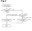
- Fig. 2 is a flowchart representing the fuel pressure control. The procedure is carried out in an interrupting manner each time a certain period of time elapses or each time the engine 16 rotates by a predetermined crank angle.
- the ECU 24 determines whether the engine 16 is in a high-temperature starting state (S100). Such determination is carried out based on the engine coolant temperature THW (alternatively, an oil temperature), which is detected by the coolant temperature sensor 40 when the engine 16 is started, or on the time elapsing from when the engine 16 is stopped to when the engine 16 is started.
- THW engine coolant temperature
- the ECU 24 determines that the engine 16 is in the high-temperature state and closes the electromagnetic valve 32 (S102). The procedure is then suspended.
- step S102 By closing the electromagnetic valve 32 in step S102, the low pressure regulator 12 is prevented from influencing the fuel in the main line 14.
- the fuel supplied to the fuel distribution pipes 18, 20 is then adjusted to the high level by the high pressure regulator 28, which is arranged in the first return line 26.
- the fuel injection valves 18a to 18d and 20a to 20d inject high-pressure fuel.
- the excessive fuel that has not been injected from the fuel injection valves 18a to 18d and 20a to 20d, out of the fuel supplied from the main line 14 to the fuel distribution pipes 18, 20, is returned to the fuel tank 2 through the high pressure regulator 28 and the first return line 26 after passing through the fuel distribution pipes 18, 20. Accordingly, in the high-temperature starting state, the fuel distribution pipes 18, 20 are cooled by the fuel supplied from the fuel tank 2. Further, even if fuel vapor is generated in the fuel distribution pipes 18 20 due to the high temperature of the engine 16 when the engine 16 is stopped, the fuel vapor is sent out from the fuel distribution pipes 18, 20 to the fuel tank 2 through the first return line 26.
- the ECU 24 determines whether the operating state of the engine 16 is in a high pressure range, in which high-pressure fuel needs to be injected, or a low pressure range, in which low-pressure fuel needs to be injected (S104).
- the high pressure range is a range of the operating state in which the engine 16 is in a high rotation state or a high load state.
- the low pressure range is a range of the operating state other than the high pressure range.
- the level of the load on the engine is determined based on, for example, the intake air amount GA detected by the intake air amount sensor 36 or a requested fuel injection amount (volume of fuel per injection) or the pedal depression amount ACCP detected by the accelerator pedal depression amount sensor 38.
- the load on the engine may be determined by taking into consideration the increase rates of the intake air amount GA, the requested fuel injection amount, or the pedal depression amount ACCP.
- step S104 If it is determined that the operating state of the engine 16 is in the low pressure range in step S104, the ECU 24 opens the electromagnetic valve 32 (S106). The procedure is then suspended.
- the low pressure regulator 12 and the high pressure regulator 28 both act on the fuel in the main line 14.
- operation of the low pressure regulator 12 precedes operation of the high pressure regulator 28.
- the low pressure regulator 12 operates in preference to the high pressure regulator 28.
- the pressure of the fuel in the fuel distribution pipes 18, 20 is thus switched to the low level.
- the fuel is injected at low pressure from the fuel injection valves 18a to 18d and 20a to 20d.
- the excessive fuel that has not been injected by the fuel injection valves 18a to 18d and 20a to 20d out of the fuel supplied from the feed pump 8 to the main line 14 through the fuel filter 10 is returned to the fuel tank 2 through the second return line 30, the electromagnetic valve 32, and the low pressure regulator 12 without flowing into the fuel distribution pipes 18, 20. Accordingly, a relatively large amount of fuel returned to the fuel tank 2 when the engine 16 is in the low load state or the low rotation state does not pass through the fuel distribution pipes 18, 20. This prevents heating of the fuel returned to the fuel tank 2. An excessive temperature rise thus does not occur in the fuel tank 2.
- step S104 If it is determined that the operating state of the engine 16 is in the high pressure range in step S104, the ECU 24 closes the electromagnetic valve 32 (S102). The procedure is then suspended.
- step S102 the low pressure regulator 12 is prevented from acting on the fuel in the main line 14, as has been described.
- the fuel in the main line 14 is thus regulated by the high pressure regulator 28. Accordingly, high-pressure fuel is injected by the fuel injection valves 18a to 18d and 20a to 20d.
- the excessive fuel that has not been injected from the fuel injection valves 18a to 18d and 20a to 20d, out of the fuel fed from the main line 14 to the fuel distribution pipes 18, 20, is returned to the fuel tank 2 through the high pressure regulator 28 and the first return line 26 after passing through the fuel distribution pipes 18, 20.
- the engine 16 since the engine 16 is in the high load state or the high rotation state, the amount of the fuel injected per unit time is great, and, correspondingly, the amount of the fuel returned to the fuel tank 2 is small. The temperature in the fuel tank 2 is thus prevented from rising.
- the injection amount per injection is adjusted by regulating the fuel pressure. Further, the injection amount per injection can be controlled by prolonging the opening period of each fuel injection valve 18a to 18d and 20a to 20d even if the injection amount per injection is small when the engine 16 is in the low load state or by shortening the opening period of the fuel injection valve 18a to 18d and 20a to 20d even if the injection amount per injection is great when the engine 16 is in the high load state. In this manner, the dynamic range of the fuel injection amount is widened.
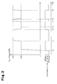
- Fig. 3 is a timing chart representing an example of control according to the illustrated embodiment of the present invention.
- the feed pump 8 is actuated. It is assumed that, at this stage, the engine 16 is not in the high-temperature starting state and the operating state of the engine 16 is in the low pressure range.
- the electromagnetic valve 32 is opened in response to an ON signal from the ECU 24 and the low pressure regulator 12 maintains the fuel pressure at the low level (t0 to t1).
- the electromagnetic valve 32 is closed in response to an OFF signal from the ECU 24.
- the high pressure regulator 28 thus maintains the fuel pressure at the high level (t1 to t2).
- the electromagnetic valve 32 is opened and the low pressure regulator 12 maintains the fuel pressure at the low level. Afterwards, the engine 16 is stopped at a certain time point between time point t3 to time point t4. When the engine 16 is started at high temperature at time point t4, or immediately after the engine 16 has been stopped, the electromagnetic valve 32 is temporarily closed and the fuel pressure rises (t4 to t5). From time point t5 at which high-temperature starting of the engine 16 is completed, the electromagnetic valve 32 is selectively opened (t5 to t6) and closed (from t6), in accordance with the engine operating state.
- the components other than the ECU 24 and the sensors 34 to 42 correspond to the fuel supply device.
- the ECU 24 corresponds to the control device controlling the fuel supply device.
- the illustrated embodiment has the following advantages.
- the present invention may be used in an in-cylinder injection internal combustion engine, which injects fuel directly into a combustion chamber of the engine 16.
- the feed pump 8 may be arranged at a position outside the fuel tank 2 and in the vicinity of the fuel tank 2.
- the electromagnetic on-off valve 32 may be arranged downstream from the low pressure regulator 12.
- the main line 14 and the first return line 26 may be connected to a portion closer to the center of the joint body of the two fuel distribution pipes 18, 20, instead of both ends of the joint body. Specifically, when excessive fuel is returned to the fuel tank 2 through the first return line 26 in the high-temperature starting state of the engine 16, some of the fuel may be exchanged between the two fuel distribution pipes 18, 20 to such an extent that insufficiency of the fuel injection amount caused by the fuel vapor does not occur.
- the internal combustion engine 16 may be an engine other than the V8 engine, or an in-line engine having a single fuel distribution pipe.
Landscapes
- Engineering & Computer Science (AREA)
- Chemical & Material Sciences (AREA)
- Combustion & Propulsion (AREA)
- Mechanical Engineering (AREA)
- General Engineering & Computer Science (AREA)
- Fuel-Injection Apparatus (AREA)
- Electrical Control Of Air Or Fuel Supplied To Internal-Combustion Engine (AREA)
Abstract
Description
- The present invention relates to a fuel supply device for an internal combustion engine capable of changing fuel pressure to supply fuel to a fuel injection valve and to a control device for the fuel supply device.
-
Patent Documents - The fuel supply device of
Patent Document 1 supplies pressurized fuel from an end of a fuel branch pipe, which serves as a fuel distribution pipe, to an internal combustion engine through a supply line and returns excessive fuel from the other end of the fuel branch pipe to a fuel tank through a return line. The return line is branched into a line that has a low pressure regulating valve and an electromagnetic valve and a line that has a high pressure regulating valve only. - The fuel supply device of
Patent Document 2 also supplies pressurized fuel from an end of a fuel gallery, which serves as a fuel distribution pipe, to the engine through a supply line. However, the fuel supply device does not include a return line through which excessive fuel is returned to a fuel tank. The supply line is branched into a line having a low pressure regulating valve and an electromagnetic valve and a line including a high pressure regulating valve only. - In the techniques of
Patent Documents - In the device of
Patent Document 1, the return line is connected to the end opposite to the end of the fuel branch pipe to which the supply line is connected. Accordingly, when the fuel injection amount is small as in a low load state or a low rotation state of the engine or fuel cutoff is carried out, a large amount of fuel that has been heated through the fuel branch pipe returns to the fuel tank via the return line, thus raising the temperature in the fuel tank. - Since the return line is not provided in the device of
Patent Document 2, the heated fuel does not return to the fuel tank so that the fuel tank is not heated. However, since the fuel gallery cannot be cooled by the fuel that passes there through, the fuel may be injected through the fuel injection valve with fuel vapor generated in the fuel gallery if the engine is started at high temperature. If the fuel vapor is injected from the fuel injection valve, the amount of fuel falls short and hampers starting of the engine, lowers control the accuracy of the air-fuel ratio, or degrades the performance of the engine due to insufficient output. Also, if catalyst bed temperature control is performed on a catalyst provided in the exhaust system of the engine, the exhaust gas cannot be sufficiently enriched. Thus, the catalyst may be heated and melted. - Patent Document 1: Japanese Laid-Open Patent Document No.
5-59976 - Patent Document 2: Japanese Laid-Open Patent Document No.
2001-221085 - Accordingly, it is an objective of the present invention to provide a fuel supply device for an internal combustion engine and a control device for the fuel supply device that prevent a fuel tank from being heated when the engine is in a low load state or a low rotation state, and prevent insufficiency of fuel injection amount when the engine is started at high temperature.
- To achieve the foregoing objective and in accordance with one aspect of the present invention, a fuel supply device is provided that supplies fuel from a fuel tank to a fuel distribution pipe of an internal combustion engine and injects the fuel from a fuel injection valve connected to the fuel distribution pipe. The device includes a main line, a fuel pump, a first return line, a second return line, a valve mechanism, a first pressure regulator, and a second pressure regulator. The main line extends from the fuel tank to the fuel distribution pipe. The fuel pump is arranged in the fuel tank or in the vicinity of the fuel tank, and pressurizes the fuel in the fuel tank and supplies the fuel to the main line. The first return line returns the fuel from the fuel distribution pipe to the fuel tank. The second return line is branched from the main line in the vicinity of the fuel pump and returns the fuel from the main line to the fuel tank. The valve mechanism is capable of selectively connecting and disconnecting the second return line with respect to the main line. The first pressure regulator is arranged in the first return line. The second pressure regulator is provided in the second return line and adjusts fuel pressure to a lower level than the first pressure regulator does.
-
-
Fig. 1 is a schematic view showing a fuel supply device for an internal combustion engine and a control device for the fuel supply device according to one embodiment of the present invention; -
Fig. 2 is a flowchart representing a fuel pressure control procedure performed by the control device ofFig. 1 ; and -
Fig. 3 is a timing chart representing an example of control executed by the control device ofFig. 1 . -
Fig. 1 is a schematic view showing a fuel supply device for an internal combustion engine according to an embodiment of the present invention and a control device for the fuel supply device. - A fuel pump module 4 is arranged in a
fuel tank 2. The fuel pump module 4 has areservoir cup 6, an electric feed pump (corresponding to a fuel pump) 8, afuel filter 10, and a low pressure regulator 12 (corresponding to a second pressure regulator). Thereservoir cup 6 accommodates thefeed pump 8 and thefuel filter 10. After having been pressurized by thefeed pump 8, the fuel is sent to thefuel filter 10 through a check valve 8a and afuel line 8b and then to amain line 14, or a fuel supply line, through acheck valve 10a. Themain line 14 extends through acowl 15 and to a firstfuel distribution pipe 18 and a secondfuel distribution pipe 20, which are provided in an internal combustion engine (a gasoline engine for a vehicle) 16. Themain line 14 sends pressurized fuel to the first and secondfuel distribution pipes engine 16 is a V8 engine and has two banks each having a line of cylinders. The firstfuel distribution pipe 18 and the secondfuel distribution pipe 20, each of which is provided in correspondence with the associated one of the two banks (the two lines of the cylinders), are connected to each other at acommunication line 22, thus forming a single joint body. In other words, the firstfuel distribution pipe 18 and the secondfuel distribution pipe 20 are connected together in such a manner as to function as an integral fuel distribution pipe. - After having been sent from the
main line 14 to a first end of the firstfuel distribution pipe 18, the fuel is fed to a first end of the secondfuel distribution pipe 20 through thefuel communication line 22, which is connected to a second end of the firstfuel distribution pipe 18. Fourfuel injection valves fuel distribution pipe 18 in correspondence with four cylinders.Fuel injection valves fuel distribution pipe 20 in correspondence with four cylinders. In other words, theengine 16 has a total of eight fuel injection valves. In response to a signal from an electronic control unit (hereinafter, referred to as an ECU) serving as a control section, the fuel injection valves 18a to 18d and 20a to 20d inject fuel to the intake ports of the corresponding cylinders. Afirst return line 26 extending to thefuel tank 2 is connected to a second end of the secondfuel distribution pipe 20, or the end opposite to the first end to which thefuel communication line 22 is connected. - Excessive fuel that has not been injected by the fuel injection valves 18a to 18d and 20a to 20d is returned to the
fuel tank 2 through thefirst return line 26. Thefirst return line 26 has a high pressure regulator 28 (corresponding to a first pressure regulator), which adjusts the pressure of the fuel to a high level (which is, for example, approximately 400 kPa). The excessive fuel is thus returned to thefuel tank 2 through thehigh pressure regulator 28 and thefirst return line 26. - A
second return line 30 is branched from themain line 14 at a position adjacent to the fuel pump module 4 and extends to thefuel tank 2. Thesecond return line 30 returns the fuel to thefuel tank 2 through thelow pressure regulator 12. Thelow pressure regulator 12 adjusts the pressure of the fuel to a level (for example, approximately 280 kPa) lower than the level brought about by thehigh pressure regulator 28. - An electromagnetic valve (an on-off valve) 32 is arranged in the
second return line 30 at a position upstream from thelow pressure regulator 12 and outside thefuel tank 2. Theelectromagnetic valve 32 selectively opens and closes thesecond return line 30 in response to a signal from theECU 24. Theelectromagnetic valve 32 is opened by receiving an ON signal from theECU 24 and closed by receiving an OFF signal. - When the
electromagnetic valve 32 is closed, thelow pressure regulator 12 does not function. The pressure of the fuel in themain line 14 is thus adjusted to a high level by thehigh pressure regulator 28 without being switched to a low level by thelow pressure regulator 12. Accordingly, the fuel is injected by the fuel injection valves 18a to 18d and 20a to 20d at high pressure at respective fuel injection timing. When theelectromagnetic valve 32 is open, thelow pressure regulator 12 adjusts the pressure of the fuel in themain line 14 to the low level in preference to thehigh pressure regulator 28. Accordingly, the fuel injection valves 18a to 18d and 20a to 20d inject the fuel at low pressure at the fuel injection timing. Through such ON-OFF control of theelectromagnetic valve 32, the fuel pressure is easily switched between the high level and the low level. - The
ECU 24 detects parameters indicating the operating state of theengine 16, such as the engine speed NE, the intake air amount GA, the accelerator pedal depression amount ACCP, the engine coolant temperature THW, and the fuel pressure PF by means of anengine speed sensor 34, an intakeair amount sensor 36, a pedaldepression amount sensor 38, acoolant temperature sensor 40, and afuel pressure sensor 42. TheECU 24 performs computation procedures based on detection results of the parameters indicating the operating state of theengine 16 and various types of data that has been stored in advance. TheECU 24 thus controls the fuel injection amount and the fuel injection timing of the fuel injection valves 18a to 18d and 20a to 20d and operation of theelectromagnetic valve 32. - Fuel pressure control performed by the
ECU 24 will be explained in the following.Fig. 2 is a flowchart representing the fuel pressure control. The procedure is carried out in an interrupting manner each time a certain period of time elapses or each time theengine 16 rotates by a predetermined crank angle. - Once the procedure is started, the
ECU 24 determines whether theengine 16 is in a high-temperature starting state (S100). Such determination is carried out based on the engine coolant temperature THW (alternatively, an oil temperature), which is detected by thecoolant temperature sensor 40 when theengine 16 is started, or on the time elapsing from when theengine 16 is stopped to when theengine 16 is started. Specifically, if the engine coolant temperature THW is higher than a reference value by which it is determined that theengine 16 is in the high-temperature state, or the time elapsed since theengine 16 has been stopped is shorter than a reference value by which it is determined that theengine 16 has radiated heat to a sufficient extent, theECU 24 determines that theengine 16 is in the high-temperature state and closes the electromagnetic valve 32 (S102). The procedure is then suspended. - By closing the
electromagnetic valve 32 in step S102, thelow pressure regulator 12 is prevented from influencing the fuel in themain line 14. The fuel supplied to thefuel distribution pipes high pressure regulator 28, which is arranged in thefirst return line 26. As a result, when theengine 16 is started at high temperature, the fuel injection valves 18a to 18d and 20a to 20d inject high-pressure fuel. - In this case, the excessive fuel that has not been injected from the fuel injection valves 18a to 18d and 20a to 20d, out of the fuel supplied from the
main line 14 to thefuel distribution pipes fuel tank 2 through thehigh pressure regulator 28 and thefirst return line 26 after passing through thefuel distribution pipes fuel distribution pipes fuel tank 2. Further, even if fuel vapor is generated in thefuel distribution pipes 18 20 due to the high temperature of theengine 16 when theengine 16 is stopped, the fuel vapor is sent out from thefuel distribution pipes fuel tank 2 through thefirst return line 26. - Contrastingly, if the
engine 16 is not in the high-temperature starting state, theECU 24 determines whether the operating state of theengine 16 is in a high pressure range, in which high-pressure fuel needs to be injected, or a low pressure range, in which low-pressure fuel needs to be injected (S104). The high pressure range is a range of the operating state in which theengine 16 is in a high rotation state or a high load state. The low pressure range is a range of the operating state other than the high pressure range. The level of the load on the engine is determined based on, for example, the intake air amount GA detected by the intakeair amount sensor 36 or a requested fuel injection amount (volume of fuel per injection) or the pedal depression amount ACCP detected by the accelerator pedaldepression amount sensor 38. Alternatively, the load on the engine may be determined by taking into consideration the increase rates of the intake air amount GA, the requested fuel injection amount, or the pedal depression amount ACCP. - If it is determined that the operating state of the
engine 16 is in the low pressure range in step S104, theECU 24 opens the electromagnetic valve 32 (S106). The procedure is then suspended. - By opening the
electromagnetic valve 32 in step S106, thelow pressure regulator 12 and thehigh pressure regulator 28 both act on the fuel in themain line 14. However, in reality, operation of thelow pressure regulator 12 precedes operation of thehigh pressure regulator 28. In other words, thelow pressure regulator 12 operates in preference to thehigh pressure regulator 28. The pressure of the fuel in thefuel distribution pipes - In this case, the excessive fuel that has not been injected by the fuel injection valves 18a to 18d and 20a to 20d out of the fuel supplied from the
feed pump 8 to themain line 14 through thefuel filter 10 is returned to thefuel tank 2 through thesecond return line 30, theelectromagnetic valve 32, and thelow pressure regulator 12 without flowing into thefuel distribution pipes fuel tank 2 when theengine 16 is in the low load state or the low rotation state does not pass through thefuel distribution pipes fuel tank 2. An excessive temperature rise thus does not occur in thefuel tank 2. - If it is determined that the operating state of the
engine 16 is in the high pressure range in step S104, theECU 24 closes the electromagnetic valve 32 (S102). The procedure is then suspended. - Through the procedure of step S102, the
low pressure regulator 12 is prevented from acting on the fuel in themain line 14, as has been described. The fuel in themain line 14 is thus regulated by thehigh pressure regulator 28. Accordingly, high-pressure fuel is injected by the fuel injection valves 18a to 18d and 20a to 20d. - Also in this case, the excessive fuel that has not been injected from the fuel injection valves 18a to 18d and 20a to 20d, out of the fuel fed from the
main line 14 to thefuel distribution pipes fuel tank 2 through thehigh pressure regulator 28 and thefirst return line 26 after passing through thefuel distribution pipes engine 16 is in the high load state or the high rotation state, the amount of the fuel injected per unit time is great, and, correspondingly, the amount of the fuel returned to thefuel tank 2 is small. The temperature in thefuel tank 2 is thus prevented from rising. - As has been described, even if the opening periods of the fuel injection valves 18a to 18d and 20a to 20d per injection are equal, the injection amount per injection is adjusted by regulating the fuel pressure. Further, the injection amount per injection can be controlled by prolonging the opening period of each fuel injection valve 18a to 18d and 20a to 20d even if the injection amount per injection is small when the
engine 16 is in the low load state or by shortening the opening period of the fuel injection valve 18a to 18d and 20a to 20d even if the injection amount per injection is great when theengine 16 is in the high load state. In this manner, the dynamic range of the fuel injection amount is widened. -
Fig. 3 is a timing chart representing an example of control according to the illustrated embodiment of the present invention. When the ignition switch is turned on at time point t0, thefeed pump 8 is actuated. It is assumed that, at this stage, theengine 16 is not in the high-temperature starting state and the operating state of theengine 16 is in the low pressure range. In this case, theelectromagnetic valve 32 is opened in response to an ON signal from theECU 24 and thelow pressure regulator 12 maintains the fuel pressure at the low level (t0 to t1). - Afterwards, if it is determined that the engine operating state is in the high pressure range at time point t1, the
electromagnetic valve 32 is closed in response to an OFF signal from theECU 24. Thehigh pressure regulator 28 thus maintains the fuel pressure at the high level (t1 to t2). - Then, if it is determined that the engine operating state is in the low pressure range due to fuel cutoff (t2 to t3), the
electromagnetic valve 32 is opened and thelow pressure regulator 12 maintains the fuel pressure at the low level. Afterwards, theengine 16 is stopped at a certain time point between time point t3 to time point t4. When theengine 16 is started at high temperature at time point t4, or immediately after theengine 16 has been stopped, theelectromagnetic valve 32 is temporarily closed and the fuel pressure rises (t4 to t5). From time point t5 at which high-temperature starting of theengine 16 is completed, theelectromagnetic valve 32 is selectively opened (t5 to t6) and closed (from t6), in accordance with the engine operating state. - In the configuration illustrated in
Fig. 1 , the components other than theECU 24 and thesensors 34 to 42 correspond to the fuel supply device. TheECU 24 corresponds to the control device controlling the fuel supply device. - The illustrated embodiment has the following advantages.
- (1) In the illustrated embodiment, the
main line 14 is connected to one end of the joint body of thefuel distribution pipes first return line 26 is connected to the other end of the joint body. Thesecond return line 30 is branched from themain line 14 in the vicinity of thefeed pump 8. Theelectromagnetic valve 32 is provided in thesecond return line 30.
When theengine 16 is in the low load state or the low rotation state in which an excessive amount of fuel may be supplied from thefeed pump 8 and a great amount of fuel returns to thefuel tank 2, theelectromagnetic valve 32 is opened so as to allow thesecond return line 30 to communicate with themain line 14. In this manner, the pressure of the fuel supplied from thefeed pump 8 is lowered by thelow pressure regulator 12, which is arranged in thesecond return line 30, and fed to thefuel distribution pipes second return line 30 to thefuel tank 2 through thelow pressure regulator 12. Since the fuel pressure is decreased to the low level by thelow pressure regulator 12, the pressure of the fuel in thefuel distribution pipes high pressure regulator 28 of thefirst return line 26. This prevents heated fuel from returning from thefuel distribution pipes fuel tank 2 via thefirst return line 26. As a result, thefuel tank 2 is not heated.
When theengine 16 is in the high-temperature starting state in which fuel vapor may be generated in thefuel distribution pipes electromagnetic valve 32 is closed. This causes thehigh pressure regulator 28 to raise the pressure of the fuel supplied from thefeed pump 8 to thefuel distribution pipes main line 14. Meanwhile, excessive fuel is returned to thefuel tank 2 through thereturn line 26. Accordingly, through supply of the large amount of the fuel from thefuel tank 2, all or substantially all of the fuel in thefuel distribution pipes fuel distribution pipes fuel tank 2 via thefirst return line 26. This immediately lowers the temperature in each of thefuel distribution pipes fuel tank 2, thus preventing the fuel vapor from being trapped in the fuel injection valves 18a to 18d and 20a to 20d. As a result, degradation of high-temperature starting performance caused by insufficiency of the fuel injection amount is suppressed.
As has been described, the illustrated embodiment prevents thefuel tank 2 from being heated when theengine 16 is in the low load state and prevents insufficiency of the fuel injection amount when theengine 16 is in the high-temperature starting state. - (2) Heating of the
fuel tank 2 when theengine 16 is in the low load state and insufficiency of the fuel injection amount when theengine 16 is in the high-temperature starting state are easily prevented through control of operation of theelectromagnetic valve 32 performed by theECU 24 in accordance with the fuel pressure control procedure represented inFig. 2 . - The illustrated embodiment may be modified as follows.
- The present invention may be used in an in-cylinder injection internal combustion engine, which injects fuel directly into a combustion chamber of the
engine 16. - The
feed pump 8 may be arranged at a position outside thefuel tank 2 and in the vicinity of thefuel tank 2. - In the
second return line 30, the electromagnetic on-offvalve 32 may be arranged downstream from thelow pressure regulator 12. - The
main line 14 and thefirst return line 26 may be connected to a portion closer to the center of the joint body of the twofuel distribution pipes fuel tank 2 through thefirst return line 26 in the high-temperature starting state of theengine 16, some of the fuel may be exchanged between the twofuel distribution pipes - The
internal combustion engine 16 may be an engine other than the V8 engine, or an in-line engine having a single fuel distribution pipe.
Claims (7)
- A fuel supply device that supplies fuel from a fuel tank to a fuel distribution pipe of an internal combustion engine and injects the fuel from a fuel injection valve connected to the fuel distribution pipe, the device comprising:a main line extending from the fuel tank to the fuel distribution pipe;a fuel pump that is arranged in the fuel tank or in the vicinity of the fuel tank, and pressurizes the fuel in the fuel tank and supplies the fuel to the main line;a first return line that returns the fuel from the fuel distribution pipe to the fuel tank;a second return line that is branched from the main line in the vicinity of the fuel pump and returns the fuel from the main line to the fuel tank;a valve mechanism capable of selectively connecting and disconnecting the second return line with respect to the main line;a first pressure regulator arranged in the first return line; anda second pressure regulator that is provided in the second return line and adjusts fuel pressure to a lower level than the first pressure regulator does.
- The fuel supply device according to claim 1, wherein the fuel distribution pipe has a first end and a second end opposite to the first end, wherein the main line being connected to the first end of the fuel distribution pipe or to a portion in the vicinity of the first end, and wherein the first return line is connected to the second end of the fuel distribution pipe or to a portion in the vicinity of the second end.
- The fuel supply device according to claims 1 or 2, wherein the internal combustion engine has a plurality of lines of cylinders, and wherein the fuel distribution pipe is a joint body of fuel distribution pipes each arranged for one of the lines of the cylinders.
- The fuel supply device according to any one of claims 1 to 3, wherein the valve mechanism is an on-off valve provided in the second return line.
- The fuel supply device according to any one of claims 1 to 4, further comprising a control section, wherein, when the engine is in a high-temperature starting state, the control section controls the valve mechanism in such a manner as to disconnect the second return line from the main line.
- The device according to claim 5, wherein the control section:determines whether the operating state of the engine is in a high pressure range, in which a high-pressure fuel needs to be injected, or in a low pressure range other than the high pressure range;controls the valve mechanism in such a manner as to disconnect the second return line from the main line when the operating state of the engine is in the high pressure range; andcontrols the valve mechanism in such a manner as to allow the second return line to communicate with the main line when the operating state of the engine is in the low pressure range.
- The device according to claim 6, wherein the high pressure range is a range of the operating state in which the engine is in a high rotation state or a high load state.
Applications Claiming Priority (2)
| Application Number | Priority Date | Filing Date | Title |
|---|---|---|---|
| JP2006343341A JP4415987B2 (en) | 2006-12-20 | 2006-12-20 | Internal combustion engine fuel supply device |
| PCT/JP2007/074288 WO2008075668A1 (en) | 2006-12-20 | 2007-12-18 | Fuel supply device for internal combustion engine and control device for the fuel supply device |
Publications (3)
| Publication Number | Publication Date |
|---|---|
| EP2096297A1 true EP2096297A1 (en) | 2009-09-02 |
| EP2096297A4 EP2096297A4 (en) | 2013-05-29 |
| EP2096297B1 EP2096297B1 (en) | 2015-03-04 |
Family
ID=39536298
Family Applications (1)
| Application Number | Title | Priority Date | Filing Date |
|---|---|---|---|
| EP07850776.1A Not-in-force EP2096297B1 (en) | 2006-12-20 | 2007-12-18 | Fuel supply device for internal combustion engine and control device for the fuel supply device |
Country Status (5)
| Country | Link |
|---|---|
| US (1) | US8122871B2 (en) |
| EP (1) | EP2096297B1 (en) |
| JP (1) | JP4415987B2 (en) |
| BR (1) | BRPI0716273A2 (en) |
| WO (1) | WO2008075668A1 (en) |
Families Citing this family (11)
| Publication number | Priority date | Publication date | Assignee | Title |
|---|---|---|---|---|
| JP5568222B2 (en) | 2008-06-16 | 2014-08-06 | 富士フイルム株式会社 | Ink composition, ink composition for ink jet recording, ink set, ink cartridge, ink jet recording method and recorded matter |
| JP5056640B2 (en) * | 2008-07-16 | 2012-10-24 | トヨタ自動車株式会社 | Engine fuel supply system |
| JP4962436B2 (en) * | 2008-07-17 | 2012-06-27 | トヨタ自動車株式会社 | Control device for in-vehicle internal combustion engine |
| JP4561906B2 (en) * | 2008-08-21 | 2010-10-13 | トヨタ自動車株式会社 | Fuel supply device for flexible fuel internal combustion engine |
| US8439016B2 (en) * | 2009-12-15 | 2013-05-14 | GM Global Technology Operations LLC | Liquefied petroleum gas engine assembly with flow control |
| JP5282779B2 (en) * | 2010-12-08 | 2013-09-04 | トヨタ自動車株式会社 | Fuel supply device for internal combustion engine |
| WO2014085758A1 (en) * | 2012-11-30 | 2014-06-05 | Thermo King Corporation | Systems and methods to regulate a pressure in a fuel delivery system |
| DE102013217810A1 (en) * | 2013-09-06 | 2015-03-12 | Robert Bosch Gmbh | Holder for fixing a fuel distributor to an internal combustion engine and connection method |
| GB201514625D0 (en) * | 2015-08-18 | 2015-09-30 | Delphi Int Operations Lux Srl | Regulator |
| US10934933B2 (en) * | 2018-08-31 | 2021-03-02 | Paccar Inc | Fuel gelling prevention using engine auto start functionality |
| JP7294236B2 (en) * | 2020-05-21 | 2023-06-20 | トヨタ自動車株式会社 | Control device for fuel supply system |
Family Cites Families (16)
| Publication number | Priority date | Publication date | Assignee | Title |
|---|---|---|---|---|
| JPH0559976A (en) | 1991-08-26 | 1993-03-09 | Hitachi Ltd | Electronically controlled fuel injection device |
| US5207203A (en) * | 1992-03-23 | 1993-05-04 | General Motors Corporation | Fuel system |
| JP2853504B2 (en) * | 1993-03-16 | 1999-02-03 | 日産自動車株式会社 | Fuel injection device for internal combustion engine |
| DE4336871A1 (en) * | 1993-10-28 | 1995-05-04 | Siemens Ag | Device for reducing the fuel temperature in the tank of a motor vehicle |
| US5558068A (en) * | 1994-05-31 | 1996-09-24 | Zexel Corporation | Solenoid valve unit for fuel injection apparatus |
| JPH08319865A (en) * | 1995-05-26 | 1996-12-03 | Mitsubishi Motors Corp | Fuel injection control device for in-cylinder internal combustion engine |
| JPH09158766A (en) | 1995-12-07 | 1997-06-17 | Nissan Motor Co Ltd | Fuel injection system for direct injection spark ignition internal combustion engine |
| DE19548278B4 (en) * | 1995-12-22 | 2007-09-13 | Robert Bosch Gmbh | Method and device for controlling an internal combustion engine |
| JP3063610B2 (en) | 1996-03-07 | 2000-07-12 | 三菱自動車工業株式会社 | Fuel supply device for internal combustion engine |
| JP3333407B2 (en) * | 1996-10-17 | 2002-10-15 | 株式会社ユニシアジェックス | Fuel supply system for direct injection gasoline internal combustion engine |
| FR2764003B1 (en) * | 1997-06-02 | 1999-08-06 | Magneti Marelli France | BLEEDING AN INJECTOR RAMP OF A DIRECT INJECTION ENGINE |
| DE19950232A1 (en) * | 1999-10-19 | 2001-04-26 | Bosch Gmbh Robert | Priming fuel supply system for internal combustion engine involves activating fuel pump(s), activating pressure control or regulating valves, determining pressure in fuel supply system |
| JP2001182588A (en) | 1999-12-28 | 2001-07-06 | Fuji Heavy Ind Ltd | Engine fuel injection control device |
| JP3922862B2 (en) | 2000-02-04 | 2007-05-30 | 株式会社日立製作所 | Fuel supply device for internal combustion engine |
| JP2002004965A (en) | 2000-06-23 | 2002-01-09 | Honda Motor Co Ltd | Fuel injection device for internal combustion engine |
| JP2003083191A (en) * | 2001-09-05 | 2003-03-19 | Hitachi Unisia Automotive Ltd | Fuel injection device |
-
2006
- 2006-12-20 JP JP2006343341A patent/JP4415987B2/en not_active Expired - Fee Related
-
2007
- 2007-12-18 BR BRPI0716273-1A2A patent/BRPI0716273A2/en not_active Application Discontinuation
- 2007-12-18 EP EP07850776.1A patent/EP2096297B1/en not_active Not-in-force
- 2007-12-18 US US12/518,281 patent/US8122871B2/en not_active Expired - Fee Related
- 2007-12-18 WO PCT/JP2007/074288 patent/WO2008075668A1/en not_active Ceased
Also Published As
| Publication number | Publication date |
|---|---|
| JP4415987B2 (en) | 2010-02-17 |
| US8122871B2 (en) | 2012-02-28 |
| JP2008157029A (en) | 2008-07-10 |
| EP2096297B1 (en) | 2015-03-04 |
| EP2096297A4 (en) | 2013-05-29 |
| BRPI0716273A2 (en) | 2015-01-20 |
| US20100006072A1 (en) | 2010-01-14 |
| WO2008075668A1 (en) | 2008-06-26 |
Similar Documents
| Publication | Publication Date | Title |
|---|---|---|
| EP2096297B1 (en) | Fuel supply device for internal combustion engine and control device for the fuel supply device | |
| EP2232043B1 (en) | System for supply of lpg, methane, ammonia, and gas in general for petrol or diesel engines with electronic pressure regulator for continuous variation of the pressure of the fuel supplied to the injectors | |
| EP1766217B1 (en) | Fuel injection control apparatus for internal combustion engine | |
| US20120310509A1 (en) | Dual fuel engine system | |
| AU2010236012B2 (en) | Liquefied Petroleum Gas Engine Assembly with Flow Control | |
| US20120266846A1 (en) | Dual fuel diesel engine system | |
| JP2008045463A (en) | Fuel injection system for supercritical fuel | |
| KR101920258B1 (en) | Method and device for controlling the fuel supply of an internal combustion engine operated with liquefied gas | |
| US20030051709A1 (en) | Method and system for controlling fuel injection | |
| JP5345692B2 (en) | Fluid accumulator device for internal combustion engine | |
| EP2871351B1 (en) | Control device for internal combustion engine | |
| JP2006242059A (en) | Vehicle fuel supply device | |
| US8534260B2 (en) | Fuel supply system | |
| JP5989406B2 (en) | Fuel pressure control device | |
| US10054098B2 (en) | Ignition timing control device for internal combustion engine | |
| EP2388460A1 (en) | Common rail fuel system for a multi-cylinder bank combustion engine with independently controlled fuel supply to each bank | |
| EP1350944A1 (en) | Gas fuel feeder of internal combustion engine | |
| US7383823B2 (en) | Fuel injection system for an internal combustion engine | |
| JP3924991B2 (en) | Internal combustion engine control device | |
| EP2077381A1 (en) | A device for supplying fuel to a combustion engine, method for operating the said device and device to control the operation of a combustion engine | |
| JP2005248807A (en) | Fuel supply device and fuel supply control device | |
| JP2004060466A (en) | Fuel injection system |
Legal Events
| Date | Code | Title | Description |
|---|---|---|---|
| PUAI | Public reference made under article 153(3) epc to a published international application that has entered the european phase |
Free format text: ORIGINAL CODE: 0009012 |
|
| 17P | Request for examination filed |
Effective date: 20090610 |
|
| AK | Designated contracting states |
Kind code of ref document: A1 Designated state(s): AT BE BG CH CY CZ DE DK EE ES FI FR GB GR HU IE IS IT LI LT LU LV MC MT NL PL PT RO SE SI SK TR |
|
| DAX | Request for extension of the european patent (deleted) | ||
| RAP1 | Party data changed (applicant data changed or rights of an application transferred) |
Owner name: TOYOTA JIDOSHA KABUSHIKI KAISHA |
|
| A4 | Supplementary search report drawn up and despatched |
Effective date: 20130503 |
|
| RIC1 | Information provided on ipc code assigned before grant |
Ipc: F02M 55/02 20060101AFI20130425BHEP Ipc: F02D 41/04 20060101ALI20130425BHEP |
|
| GRAP | Despatch of communication of intention to grant a patent |
Free format text: ORIGINAL CODE: EPIDOSNIGR1 |
|
| INTG | Intention to grant announced |
Effective date: 20140922 |
|
| GRAS | Grant fee paid |
Free format text: ORIGINAL CODE: EPIDOSNIGR3 |
|
| GRAA | (expected) grant |
Free format text: ORIGINAL CODE: 0009210 |
|
| AK | Designated contracting states |
Kind code of ref document: B1 Designated state(s): AT BE BG CH CY CZ DE DK EE ES FI FR GB GR HU IE IS IT LI LT LU LV MC MT NL PL PT RO SE SI SK TR |
|
| REG | Reference to a national code |
Ref country code: GB Ref legal event code: FG4D |
|
| REG | Reference to a national code |
Ref country code: CH Ref legal event code: EP |
|
| REG | Reference to a national code |
Ref country code: IE Ref legal event code: FG4D |
|
| REG | Reference to a national code |
Ref country code: AT Ref legal event code: REF Ref document number: 714123 Country of ref document: AT Kind code of ref document: T Effective date: 20150415 |
|
| REG | Reference to a national code |
Ref country code: DE Ref legal event code: R096 Ref document number: 602007040520 Country of ref document: DE Effective date: 20150416 |
|
| REG | Reference to a national code |
Ref country code: AT Ref legal event code: MK05 Ref document number: 714123 Country of ref document: AT Kind code of ref document: T Effective date: 20150304 Ref country code: NL Ref legal event code: VDEP Effective date: 20150304 |
|
| PG25 | Lapsed in a contracting state [announced via postgrant information from national office to epo] |
Ref country code: FI Free format text: LAPSE BECAUSE OF FAILURE TO SUBMIT A TRANSLATION OF THE DESCRIPTION OR TO PAY THE FEE WITHIN THE PRESCRIBED TIME-LIMIT Effective date: 20150304 Ref country code: ES Free format text: LAPSE BECAUSE OF FAILURE TO SUBMIT A TRANSLATION OF THE DESCRIPTION OR TO PAY THE FEE WITHIN THE PRESCRIBED TIME-LIMIT Effective date: 20150304 Ref country code: LT Free format text: LAPSE BECAUSE OF FAILURE TO SUBMIT A TRANSLATION OF THE DESCRIPTION OR TO PAY THE FEE WITHIN THE PRESCRIBED TIME-LIMIT Effective date: 20150304 Ref country code: SE Free format text: LAPSE BECAUSE OF FAILURE TO SUBMIT A TRANSLATION OF THE DESCRIPTION OR TO PAY THE FEE WITHIN THE PRESCRIBED TIME-LIMIT Effective date: 20150304 |
|
| REG | Reference to a national code |
Ref country code: LT Ref legal event code: MG4D |
|
| PG25 | Lapsed in a contracting state [announced via postgrant information from national office to epo] |
Ref country code: GR Free format text: LAPSE BECAUSE OF FAILURE TO SUBMIT A TRANSLATION OF THE DESCRIPTION OR TO PAY THE FEE WITHIN THE PRESCRIBED TIME-LIMIT Effective date: 20150605 Ref country code: LV Free format text: LAPSE BECAUSE OF FAILURE TO SUBMIT A TRANSLATION OF THE DESCRIPTION OR TO PAY THE FEE WITHIN THE PRESCRIBED TIME-LIMIT Effective date: 20150304 Ref country code: AT Free format text: LAPSE BECAUSE OF FAILURE TO SUBMIT A TRANSLATION OF THE DESCRIPTION OR TO PAY THE FEE WITHIN THE PRESCRIBED TIME-LIMIT Effective date: 20150304 |
|
| REG | Reference to a national code |
Ref country code: DE Ref legal event code: R084 Ref document number: 602007040520 Country of ref document: DE |
|
| PG25 | Lapsed in a contracting state [announced via postgrant information from national office to epo] |
Ref country code: NL Free format text: LAPSE BECAUSE OF FAILURE TO SUBMIT A TRANSLATION OF THE DESCRIPTION OR TO PAY THE FEE WITHIN THE PRESCRIBED TIME-LIMIT Effective date: 20150304 |
|
| PG25 | Lapsed in a contracting state [announced via postgrant information from national office to epo] |
Ref country code: RO Free format text: LAPSE BECAUSE OF FAILURE TO SUBMIT A TRANSLATION OF THE DESCRIPTION OR TO PAY THE FEE WITHIN THE PRESCRIBED TIME-LIMIT Effective date: 20150304 Ref country code: SK Free format text: LAPSE BECAUSE OF FAILURE TO SUBMIT A TRANSLATION OF THE DESCRIPTION OR TO PAY THE FEE WITHIN THE PRESCRIBED TIME-LIMIT Effective date: 20150304 Ref country code: EE Free format text: LAPSE BECAUSE OF FAILURE TO SUBMIT A TRANSLATION OF THE DESCRIPTION OR TO PAY THE FEE WITHIN THE PRESCRIBED TIME-LIMIT Effective date: 20150304 Ref country code: CZ Free format text: LAPSE BECAUSE OF FAILURE TO SUBMIT A TRANSLATION OF THE DESCRIPTION OR TO PAY THE FEE WITHIN THE PRESCRIBED TIME-LIMIT Effective date: 20150304 Ref country code: PT Free format text: LAPSE BECAUSE OF FAILURE TO SUBMIT A TRANSLATION OF THE DESCRIPTION OR TO PAY THE FEE WITHIN THE PRESCRIBED TIME-LIMIT Effective date: 20150706 |
|
| PG25 | Lapsed in a contracting state [announced via postgrant information from national office to epo] |
Ref country code: PL Free format text: LAPSE BECAUSE OF FAILURE TO SUBMIT A TRANSLATION OF THE DESCRIPTION OR TO PAY THE FEE WITHIN THE PRESCRIBED TIME-LIMIT Effective date: 20150304 Ref country code: IS Free format text: LAPSE BECAUSE OF FAILURE TO SUBMIT A TRANSLATION OF THE DESCRIPTION OR TO PAY THE FEE WITHIN THE PRESCRIBED TIME-LIMIT Effective date: 20150704 |
|
| REG | Reference to a national code |
Ref country code: DE Ref legal event code: R097 Ref document number: 602007040520 Country of ref document: DE |
|
| PLBE | No opposition filed within time limit |
Free format text: ORIGINAL CODE: 0009261 |
|
| STAA | Information on the status of an ep patent application or granted ep patent |
Free format text: STATUS: NO OPPOSITION FILED WITHIN TIME LIMIT |
|
| PG25 | Lapsed in a contracting state [announced via postgrant information from national office to epo] |
Ref country code: DK Free format text: LAPSE BECAUSE OF FAILURE TO SUBMIT A TRANSLATION OF THE DESCRIPTION OR TO PAY THE FEE WITHIN THE PRESCRIBED TIME-LIMIT Effective date: 20150304 |
|
| 26N | No opposition filed |
Effective date: 20151207 |
|
| PG25 | Lapsed in a contracting state [announced via postgrant information from national office to epo] |
Ref country code: SI Free format text: LAPSE BECAUSE OF FAILURE TO SUBMIT A TRANSLATION OF THE DESCRIPTION OR TO PAY THE FEE WITHIN THE PRESCRIBED TIME-LIMIT Effective date: 20150304 |
|
| PG25 | Lapsed in a contracting state [announced via postgrant information from national office to epo] |
Ref country code: BE Free format text: LAPSE BECAUSE OF NON-PAYMENT OF DUE FEES Effective date: 20151231 |
|
| REG | Reference to a national code |
Ref country code: DE Ref legal event code: R119 Ref document number: 602007040520 Country of ref document: DE |
|
| PG25 | Lapsed in a contracting state [announced via postgrant information from national office to epo] |
Ref country code: LU Free format text: LAPSE BECAUSE OF FAILURE TO SUBMIT A TRANSLATION OF THE DESCRIPTION OR TO PAY THE FEE WITHIN THE PRESCRIBED TIME-LIMIT Effective date: 20151218 Ref country code: MC Free format text: LAPSE BECAUSE OF FAILURE TO SUBMIT A TRANSLATION OF THE DESCRIPTION OR TO PAY THE FEE WITHIN THE PRESCRIBED TIME-LIMIT Effective date: 20150304 |
|
| REG | Reference to a national code |
Ref country code: CH Ref legal event code: PL |
|
| GBPC | Gb: european patent ceased through non-payment of renewal fee |
Effective date: 20151218 |
|
| PG25 | Lapsed in a contracting state [announced via postgrant information from national office to epo] |
Ref country code: BE Free format text: LAPSE BECAUSE OF FAILURE TO SUBMIT A TRANSLATION OF THE DESCRIPTION OR TO PAY THE FEE WITHIN THE PRESCRIBED TIME-LIMIT Effective date: 20150304 |
|
| REG | Reference to a national code |
Ref country code: IE Ref legal event code: MM4A |
|
| REG | Reference to a national code |
Ref country code: FR Ref legal event code: ST Effective date: 20160831 |
|
| PG25 | Lapsed in a contracting state [announced via postgrant information from national office to epo] |
Ref country code: DE Free format text: LAPSE BECAUSE OF NON-PAYMENT OF DUE FEES Effective date: 20160701 Ref country code: LI Free format text: LAPSE BECAUSE OF NON-PAYMENT OF DUE FEES Effective date: 20151231 Ref country code: GB Free format text: LAPSE BECAUSE OF NON-PAYMENT OF DUE FEES Effective date: 20151218 Ref country code: IE Free format text: LAPSE BECAUSE OF NON-PAYMENT OF DUE FEES Effective date: 20151218 Ref country code: CH Free format text: LAPSE BECAUSE OF NON-PAYMENT OF DUE FEES Effective date: 20151231 |
|
| PG25 | Lapsed in a contracting state [announced via postgrant information from national office to epo] |
Ref country code: FR Free format text: LAPSE BECAUSE OF NON-PAYMENT OF DUE FEES Effective date: 20151231 |
|
| PG25 | Lapsed in a contracting state [announced via postgrant information from national office to epo] |
Ref country code: IT Free format text: LAPSE BECAUSE OF NON-PAYMENT OF DUE FEES Effective date: 20151218 |
|
| PG25 | Lapsed in a contracting state [announced via postgrant information from national office to epo] |
Ref country code: BG Free format text: LAPSE BECAUSE OF FAILURE TO SUBMIT A TRANSLATION OF THE DESCRIPTION OR TO PAY THE FEE WITHIN THE PRESCRIBED TIME-LIMIT Effective date: 20150304 Ref country code: HU Free format text: LAPSE BECAUSE OF FAILURE TO SUBMIT A TRANSLATION OF THE DESCRIPTION OR TO PAY THE FEE WITHIN THE PRESCRIBED TIME-LIMIT; INVALID AB INITIO Effective date: 20071218 |
|
| PG25 | Lapsed in a contracting state [announced via postgrant information from national office to epo] |
Ref country code: CY Free format text: LAPSE BECAUSE OF FAILURE TO SUBMIT A TRANSLATION OF THE DESCRIPTION OR TO PAY THE FEE WITHIN THE PRESCRIBED TIME-LIMIT Effective date: 20150304 |
|
| PG25 | Lapsed in a contracting state [announced via postgrant information from national office to epo] |
Ref country code: MT Free format text: LAPSE BECAUSE OF FAILURE TO SUBMIT A TRANSLATION OF THE DESCRIPTION OR TO PAY THE FEE WITHIN THE PRESCRIBED TIME-LIMIT Effective date: 20150304 Ref country code: TR Free format text: LAPSE BECAUSE OF FAILURE TO SUBMIT A TRANSLATION OF THE DESCRIPTION OR TO PAY THE FEE WITHIN THE PRESCRIBED TIME-LIMIT Effective date: 20150304 |