EP2096246A1 - Device provided with a guide, rail system and transport mechanism for use in such a device - Google Patents
Device provided with a guide, rail system and transport mechanism for use in such a device Download PDFInfo
- Publication number
- EP2096246A1 EP2096246A1 EP09153572A EP09153572A EP2096246A1 EP 2096246 A1 EP2096246 A1 EP 2096246A1 EP 09153572 A EP09153572 A EP 09153572A EP 09153572 A EP09153572 A EP 09153572A EP 2096246 A1 EP2096246 A1 EP 2096246A1
- Authority
- EP
- European Patent Office
- Prior art keywords
- running surfaces
- transport mechanism
- carrier
- track
- pair
- Prior art date
- Legal status (The legal status is an assumption and is not a legal conclusion. Google has not performed a legal analysis and makes no representation as to the accuracy of the status listed.)
- Granted
Links
- 230000007723 transport mechanism Effects 0.000 title claims abstract description 70
- 239000000969 carrier Substances 0.000 claims description 5
- 230000002093 peripheral effect Effects 0.000 claims description 5
- 238000010276 construction Methods 0.000 description 5
- 238000006073 displacement reaction Methods 0.000 description 4
- 238000001125 extrusion Methods 0.000 description 3
- 230000003014 reinforcing effect Effects 0.000 description 2
- 229910000831 Steel Inorganic materials 0.000 description 1
- XAGFODPZIPBFFR-UHFFFAOYSA-N aluminium Chemical compound [Al] XAGFODPZIPBFFR-UHFFFAOYSA-N 0.000 description 1
- 229910052782 aluminium Inorganic materials 0.000 description 1
- 239000004411 aluminium Substances 0.000 description 1
- 238000004519 manufacturing process Methods 0.000 description 1
- 238000009420 retrofitting Methods 0.000 description 1
- 239000010959 steel Substances 0.000 description 1
- 230000003319 supportive effect Effects 0.000 description 1
Images
Classifications
-
- E—FIXED CONSTRUCTIONS
- E05—LOCKS; KEYS; WINDOW OR DOOR FITTINGS; SAFES
- E05D—HINGES OR SUSPENSION DEVICES FOR DOORS, WINDOWS OR WINGS
- E05D15/00—Suspension arrangements for wings
- E05D15/06—Suspension arrangements for wings for wings sliding horizontally more or less in their own plane
- E05D15/0604—Suspension arrangements for wings for wings sliding horizontally more or less in their own plane allowing an additional movement
- E05D15/0608—Suspension arrangements for wings for wings sliding horizontally more or less in their own plane allowing an additional movement caused by track lay-out
- E05D15/0613—Suspension arrangements for wings for wings sliding horizontally more or less in their own plane allowing an additional movement caused by track lay-out with multi-directional trolleys
-
- E—FIXED CONSTRUCTIONS
- E05—LOCKS; KEYS; WINDOW OR DOOR FITTINGS; SAFES
- E05Y—INDEXING SCHEME ASSOCIATED WITH SUBCLASSES E05D AND E05F, RELATING TO CONSTRUCTION ELEMENTS, ELECTRIC CONTROL, POWER SUPPLY, POWER SIGNAL OR TRANSMISSION, USER INTERFACES, MOUNTING OR COUPLING, DETAILS, ACCESSORIES, AUXILIARY OPERATIONS NOT OTHERWISE PROVIDED FOR, APPLICATION THEREOF
- E05Y2201/00—Constructional elements; Accessories therefor
- E05Y2201/60—Suspension or transmission members; Accessories therefor
- E05Y2201/606—Accessories therefor
- E05Y2201/61—Cooperation between suspension or transmission members
- E05Y2201/612—Cooperation between suspension or transmission members between carriers and rails
-
- E—FIXED CONSTRUCTIONS
- E05—LOCKS; KEYS; WINDOW OR DOOR FITTINGS; SAFES
- E05Y—INDEXING SCHEME ASSOCIATED WITH SUBCLASSES E05D AND E05F, RELATING TO CONSTRUCTION ELEMENTS, ELECTRIC CONTROL, POWER SUPPLY, POWER SIGNAL OR TRANSMISSION, USER INTERFACES, MOUNTING OR COUPLING, DETAILS, ACCESSORIES, AUXILIARY OPERATIONS NOT OTHERWISE PROVIDED FOR, APPLICATION THEREOF
- E05Y2201/00—Constructional elements; Accessories therefor
- E05Y2201/60—Suspension or transmission members; Accessories therefor
- E05Y2201/622—Suspension or transmission members elements
- E05Y2201/688—Rollers
- E05Y2201/692—Rollers having vertical axes
-
- E—FIXED CONSTRUCTIONS
- E05—LOCKS; KEYS; WINDOW OR DOOR FITTINGS; SAFES
- E05Y—INDEXING SCHEME ASSOCIATED WITH SUBCLASSES E05D AND E05F, RELATING TO CONSTRUCTION ELEMENTS, ELECTRIC CONTROL, POWER SUPPLY, POWER SIGNAL OR TRANSMISSION, USER INTERFACES, MOUNTING OR COUPLING, DETAILS, ACCESSORIES, AUXILIARY OPERATIONS NOT OTHERWISE PROVIDED FOR, APPLICATION THEREOF
- E05Y2800/00—Details, accessories and auxiliary operations not otherwise provided for
- E05Y2800/20—Combinations of elements
- E05Y2800/21—Combinations of elements of identical elements, e.g. of identical compression springs
-
- E—FIXED CONSTRUCTIONS
- E05—LOCKS; KEYS; WINDOW OR DOOR FITTINGS; SAFES
- E05Y—INDEXING SCHEME ASSOCIATED WITH SUBCLASSES E05D AND E05F, RELATING TO CONSTRUCTION ELEMENTS, ELECTRIC CONTROL, POWER SUPPLY, POWER SIGNAL OR TRANSMISSION, USER INTERFACES, MOUNTING OR COUPLING, DETAILS, ACCESSORIES, AUXILIARY OPERATIONS NOT OTHERWISE PROVIDED FOR, APPLICATION THEREOF
- E05Y2800/00—Details, accessories and auxiliary operations not otherwise provided for
- E05Y2800/26—Form or shape
- E05Y2800/268—Form or shape cylindrical; disc-shaped; circular
-
- E—FIXED CONSTRUCTIONS
- E05—LOCKS; KEYS; WINDOW OR DOOR FITTINGS; SAFES
- E05Y—INDEXING SCHEME ASSOCIATED WITH SUBCLASSES E05D AND E05F, RELATING TO CONSTRUCTION ELEMENTS, ELECTRIC CONTROL, POWER SUPPLY, POWER SIGNAL OR TRANSMISSION, USER INTERFACES, MOUNTING OR COUPLING, DETAILS, ACCESSORIES, AUXILIARY OPERATIONS NOT OTHERWISE PROVIDED FOR, APPLICATION THEREOF
- E05Y2900/00—Application of doors, windows, wings or fittings thereof
- E05Y2900/10—Application of doors, windows, wings or fittings thereof for buildings or parts thereof
- E05Y2900/13—Type of wing
- E05Y2900/142—Partition walls
Definitions
- the application relates to a device provided with a guide having a first pair of substantially parallel running surfaces, which are placed along a first track at a lateral distance apart, and a second pair of substantially parallel running surfaces, which are placed along a second track at a lateral distance apart, which second pair, at a crossing or junction, extends transversely to the first pair of running surfaces, and further provided with at least one carrier displaceable over the running surfaces, which carrier is provided with a bearing axle, extending transversely to the running surfaces, for fastening of a load, which bearing axle extends between the running surfaces.
- the application also relates to a rail system and a transport mechanism for use in such a device.
- a device of the abovementioned sort, for the displacement of mobile wall panels along a rail system mounted on the ceiling, is known from US-A-5,406,676 .
- the known displaceable wall system comprises a rail in the form of a tubular extrusion profile.
- wheel sets of a carrier are guided with respectively two wheels placed one above the other, which wheels are rotatable about a vertically directed axle and are aligned substantially horizontally.
- the wheels have bevelled side faces, which engage with running surfaces of the extrusion profile.
- the bottommost wheel runs over two bottommost running surfaces, and the above-situated wheel runs over a single topmost running surface.
- the wall panels are suspended from the vertical axle which extends downwards between the running surfaces.
- the rails can be provided with junctions, such as T-junctions and crossings. This makes it possible to manoeuvre the wheel sets at these sites in a plurality of directions. Should the wall panels be suspended from two placed-apart carriers, it is additionally possible to position the panel in a number of ways, by, for example, rotating the panel, in which case the panels move, of course, along differently orientated rails.
- the wall panels of the known device can be displaced over the rails relatively easily and with little force.
- the wall panels can be flexibly positioned.
- a drawback of the known device lies in the fact that, at crossings, at least one of the running surfaces of the rails is interrupted and the wheel running thereon is not supported. This means that the remaining wheel gets to endure the full load of the wall panels. This makes the load-bearing capacity of the carrier limited, since the bearing load is defined by a single wheel. Owing to the large forces which are exerted upon the wheels and the rails when a crossing is passed through, the rails and the carrier have to be made of steel.
- relatively heavy objects such as, for example, wall panels with a height of 5-13 m
- a transport mechanism which is situated close to the crossing or junction and which is movable between a take-up position in the first track, for load-bearing engagement with the carrier, and a delivery position in the second track, for release of the carrier.
- the transport mechanism may be situated with an offset with respect to the centreline of the crossing or junction.
- the transport mechanism may be placed at a distance from the running surfaces.
- the transport mechanism may be used to engage the carrier, transport the carrier over the crossing or junction, and release the carrier in the second track.
- the load is temporarily taken over in the region of an interruption of the running surfaces. The user can hence move the carrier along a crossing or branch with a continuous movement.
- the rail system is not subjected to unnecessarily heavy load, so that this can be lightly constructed, for example as an aluminium extrusion profile.
- DE 1957004 discloses a mobile wall system having a movable turntable for forming a selective connection to one of two tracks, which each have a pair of transversely situated running surfaces for supporting the runners of the panels.
- the turntable acts as a points switch between a transport position of the panels and a parking position and comprises a sub-section of the running surfaces that remains stationary as the runners are displaced from the first track to the second track via the turntable.
- the carrier may comprise a slide block, but may also be constructed, for example, as one or more wheels arranged rotatably about a wheel axle.
- the axle of the wheels can extend parallel to the running surfaces.
- the axle of the wheels is situated transversely to the running surfaces, as described in US-A-5,406,676 .
- the load-bearing axle here extends in the extension of the wheel axle of the at least one running wheel, which with bevelled side faces rolls over the running surfaces.
- the load which can be displaced with the device may comprise any load, such as an object which is moved through a room, such as in the assembly or manufacture of a product, a foodstuff, or some other object.
- the load may be formed by a wall panel having a relatively large dimension, such as a height of between 5 m and higher, for example 13-20 m. These panels can be guided manually by the user along the tracks to a desired position, such as a functional position, which divides a room into parts, and a parking position, in which the panels are placed flat one against the other.
- the runners of the panels are supported such that the panels can be quickly and easily manipulated along the branch or crossing with just slight application of force, so that the panels can be brought easily into position even by less strong members of staff.
- the rails and especially the running surfaces can be lightly constructed, so that a wall system is obtained which can be easily transported and assembled and which is relatively cheap.
- US-A-5,295,281 discloses a mobile wall system in which the carrier comprises two pairs of wheels, which are rotatable about respective axles arranged perpendicular to each other. Hence, when a crossing is passed through, at least two runners in each case remain in contact with the running surfaces.
- the construction is relatively complex, however, and demands for each panel an extra pair of runners.
- the transport mechanism comprises a supporting body which is pivotable.
- the pivotable construction of the transport mechanism ensures a simple movement of the supporting body in its movement from the take-up position into the delivery position.
- the transport mechanism can hence be made relatively simply and cheaply.
- the rotation axle stands perpendicular to the running surfaces. This construction ensures that the play of forces upon the transport mechanism during the movement from the take-up position to the delivery position remains relatively equal. This simplifies the required construction of the transport mechanism.
- the supporting body may be pivotable around a pivot axis.
- the pivot axis may be, in an embodiment, positioned with an offset with respect to the centre of the crossing or junction.
- the running surfaces are fastened to side walls situated transversely to the running surfaces, the carrier being situated between the side walls and the pivot axle being mounted close to the crossing or junction along an outer side of the side walls, which side walls, close to the pivot axle, are provided with a slot through which the transport mechanism reaches to between the running surfaces.
- the mounting of the pivot axle on the outer side of the side walls and the provision of a slot in the side walls of the rails ensures that existing rail systems can be adapted and can be provided with a transport mechanism by retrofitting. On the outer side of the side walls there is additionally enough place for the mounting of the transport mechanism.
- the transport mechanism can hence be made sufficiently strong.
- the placement of the pivot axle at a distance from the running surfaces, in combination with a transport mechanism reaching to between the running surfaces also ensures that an accurate transfer of the carrier from a first track to a second track is possible.
- a turntable crossing for a guiding rail is disclosed.
- a carrier having a load may be provided in the guiding rail.
- a crossing may be provided, to enable the load to be displaced in multiple directions.
- the crossing is formed by four rails, aligned towards a central crossing point.
- a turntable having four rail endings.
- the carrier may be positioned into the rail ending, and then the turntable may be rotated, to align the rail ending with another rail. There, the carrier may be moved out of the rail ending, and into the rail.
- the turntable shown is relatively large and complex. Due to the relatively large size of the turntable, the forces acting on the turntable when positioning a carrier, will tilt the turntable.
- the tilting will result in misalignment of the rail endings with the rail. This makes it difficult to transport the carrier from the turntable to the rail.
- the pivot axis coincides with the centre of the crossing. This results in the fact that a relatively large movement is necessary for the carrier to be transported from one rail to the other.
- the transport mechanism comprises a disc-shaped body having a bearing surface situated substantially parallel to the running surfaces.
- the rim of the disc can be provided with at least two cavities, following one behind the other in the peripheral direction. The cavities are suitable for receiving the carrier therein. The carrier is hence positioned relatively stably as the carrier is transferred from the first to the second track.
- the disc-shaped body can be realized such that it is provided along the periphery with at least two locking slots, which cooperate with a stop member, arranged fixedly with respect to the pivot axle, for securing the disc-shaped body in a predetermined angular position.
- the stop member can be, for example, an engaging element, which engages in a locking slot.
- the predetermined angular position can be, for example, a position of the transport mechanism which is receptive to the carrier. The transport mechanism, if not in use, can hence no longer move involuntarily out of this receiving position.
- At least one running surface of each track is realized as a first running surface, the device further comprising a second running surface situated at a transverse distance above the first, and the carrier comprising two bevelled wheels situated at a transverse distance apart, which are rotatable about a wheel axle situated transversely to the running surfaces, which wheels engage with their bevel with respective running surfaces situated at a transverse distance apart.
- This embodiment has the advantage that the transport mechanism can easily engage with the wheel supported by a running surface.
- the wheel axle situated transversely to the running surfaces makes it possible to easily engage the carrier. This simplifies the transport from the first track to the second track in case of a change of direction.
- the upper bevelled wheel engages with the transport mechanism. Additionally, the lower bevelled wheel may engage the first running surface. This way, both wheels are continuously supported during the transport.
- the first and second pair of running surfaces intersect at equal height.
- the carrier can hence be transferred at a same height. Accordingly, there are no height differences which need to be bridged. This simplifies the construction and guarantees a minimal expenditure of force by a user in the displacement of a panel and the transfer of the carrying device from a first track to a second track.
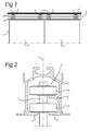
- Fig. 1 shows a known device 1 for displaceably suspended panels 10 according to the prior art.
- the device 1 is provided with a guide 2 provided with substantially parallel running surfaces 5, 8.
- the device 1 is provided with carriers 6 suspended displaceably over the running surfaces 5, 8.
- the carrier 6 is provided with a bearing axle 7, extending transversely to the running surfaces 5, for fastening of a load 10, such as, for example, a wall panel.
- the bearing axle 7 extends between the running surfaces 5, 8, as shown in Fig. 2 .
- Fig. 2 shows a detail of a cross section of a carrier 6 in a guide 2 of a device 1 for displaceably suspended panels 10 according to the prior art.
- the carrier 6 comprises a bearing axle 7, which reaches to between the running surfaces 5.
- the carrier is provided with two bevelled wheels 13, 14, which are situated at a transverse distance apart and are rotatable about a wheel axle 17 situated transversely to the running surfaces 5, 8.
- the wheels engage with their bevel with respective running surfaces 5, 8 situated at a transverse distance apart.
- the device 1 for displaceably suspended panels can be provided with intersections, where different supporting rail segments meet. It is thus possible to displace panels in a desired direction.
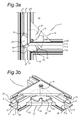
- Fig. 3a shows a cross-sectional top view of a device 1 having a first pair, placed along a first track 3, of substantially parallel running surfaces 5, 8 situated at a lateral distance apart. Extending transversely to the first track 3 is a second track 4. The second track 4 comprises substantially parallel running surfaces 5, 8 situated at a lateral distance apart. A carrier, as shown in Fig. 2 , is displaceable over the running surfaces 5, 8.
- Figure 3b shows the same junction in a perspective view.
- the first track 3 and the second track 4 form a substantially T-shaped junction 9.
- the device 1, close to the junction 9, is provided with a transport mechanism 12.
- the transport mechanism 12 may be mainly aligned into the corner formed by the two tracks at the junction.
- the transport mechanism may be attached by means of one or two reinforcing elements.
- the reinforcing elements may, for instance, be triangular plates.
- the plates may be connected to the first and second rail. For instance, one plate may be connected to the top of the two rails, and one plate may be connected to the bottom of the two rails. In between the plates, the transport mechanism may be provided.
- the transport mechanism 12 is movable between a take-up position RC in the first track 3, for load-bearing engagement with the carrier 6, and a delivery position in the second track 4, for release of the carrier.
- the transport mechanism 12 comprises a supporting body 18.
- the supporting body 18 is rotatable about a pivot axle 19.
- the pivot axle 19 stands perpendicular to the running surfaces 5, 8.
- the running surfaces 5, 8 are placed transversely to side walls 20, and the carrier is displaceable between the side walls 20 over the running surfaces 5, 8.
- the pivot axle 19 of the transport mechanism 12 is mounted along an outer side 21 of the side walls 20. Close to the pivot axle 19 there is placed a slot 22 through which the transport mechanism 12 reaches to between the running surfaces 5, 8.
- the transport mechanism 12 can comprise a disc-shaped body 24.
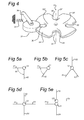
- Fig. 4 shows one embodiment of the disc-shaped body 24, having a bearing surface 26 situated substantially parallel to the running surfaces.
- the disc-shaped body comprises at least two cavities 29, following one behind the other in the peripheral direction 28.
- the disc-shaped body shown in Fig. 4 comprises four cavities 29, 29', 29'', 29'''. The cavities serve for the stable and supportive reception of the unsupported wheel of the carrier as the carrier is transported on the transport mechanism from a take-up position RC to a delivery position RL.
- the disc-shaped body shown in Fig. 4 comprises four locking slots 30, which cooperate with a spring-loaded stop member 31 which is fixedly arranged with respect to the pivot axle 19.
- the stop member 31 ensures that the disc-shaped body 24 can undergo no unwanted rotations.
- the disc-shaped body if not in use, will hence always be in a receptive position for the take-up, transportation and, subsequently, delivery of the carrier. It is possible to provide the disc-shaped body 24 with more or fewer locking slots.
- the disc-shaped body 24 is provided with at least two locking slots 30.
- the locking slots 30 can also be realized in such a way that they additionally serve for the guidance and take-up of a bearing axle 7 of a carrier 6 according to Fig. 2 , for the purpose of making the transport mechanism 12 engage with the carrier in a load-bearing manner.
- the carrier 6, in an embodiment as shown in Fig. 2 is displaceable along a first track 3 of the device 1.
- the carrier here runs with a first wheel 13 over a first running surface 5 and with a second wheel 14 over a second running surface 8.
- the second wheel 14 of the carrier will be lifted from the second running surface 8 and will land on a cavity 29 of the disc-shaped body 24 of the transport mechanism 12.
- the transport mechanism will now engage with the carrier in a load-bearing manner.
- the spring-loaded stop member 31 which cooperates with the locking slots 30 of the disc-shaped body 24, the latter will encounter some rotational resistance.
- the user then notices that the carrier 6 is at or close to the junction 9, whereafter the user has the option of making the carrier 6 undergo a change of direction.
- the user has the option of moving the carrier further along the first track 3.
- the user has the option of moving the carrier to the second track 4.
- the user has subsequently to move the carrier onward in the desired direction.
- the disc-shaped body 24 will here rotate over a predetermined angular distance, after which the transport mechanism 12 finds itself in a delivery position.
- the transport mechanism is provided with a stop member 31, this in the delivery position will re-engage with a locking slot 30.
- the user then knows that the disc-shaped body 24 is back in a delivery position.
- the user can then move the carrier onward in the desired direction.
- the user may decide to reuse the transport mechanism 12 to displace the carrier in another direction or into another track.
- FIGs. 5a-e Possible embodiments of the junction 9 in which the transport mechanism 12 is usable are shown in Figs. 5a-e .
- Fig. 5a shows a junction 9, which is provided with a first rail 41 and a second rail 42.
- the two rails make an angle of 90° to each other.
- the rails each comprise a guide having running surfaces over which a carrier is movable.
- the transport mechanism ensures that the carrier is easily movable through the right angle.
- Fig. 5b shows an embodiment as in Fig. 5a , only that the two rails now make an angle to each other which is equal to ⁇ .
- the device can additionally be provided with three rails 51,52,53, the rails mutually possessing an equal angular spacing, as shown in Fig. 5c . It is further possible to vary the angles one to another.
- the device can create a junction having four rails.
- the angles between the rails can in this case vary.
- Fig. 5d a particularly advantageous embodiment is represented.
- the junction is here provided with four rails 61, 62, 63, 64, which form a crossing.
- a transport mechanism 12 This embodiment makes it possible to use a crossing in the device, the transport mechanism engaging with the carrier in a load-bearing manner.
- the carrier can here be placed from a first branch onwards on the transport mechanism.
- the user can subsequently move the carrier rotatably in the direction of the different delivery positions.
- the transport mechanism can here act as a carrousel. Once the carrier has the desired position, the user can move the carrier onward in the desired direction.
- junctions are, of course, conceivable. For instance, it is possible to use more than four rails, or place different transport mechanisms relatively close together, in order to obtain a desired junction.
- a transport mechanism 12 having a first track 74 and a second track 71 is connected to a transport mechanism 12' having a first track 73 and a second track 73.
- the carrier can then be moved from the first transport mechanism 12 to the second transport mechanism 12'. In this way, an alternative crossing having four tracks is feasible.
Landscapes
- Engineering & Computer Science (AREA)
- Mechanical Engineering (AREA)
- Handcart (AREA)
- Conveying And Assembling Of Building Elements In Situ (AREA)
Abstract
Description
- The application relates to a device provided with a guide having a first pair of substantially parallel running surfaces, which are placed along a first track at a lateral distance apart, and a second pair of substantially parallel running surfaces, which are placed along a second track at a lateral distance apart, which second pair, at a crossing or junction, extends transversely to the first pair of running surfaces, and further provided with at least one carrier displaceable over the running surfaces, which carrier is provided with a bearing axle, extending transversely to the running surfaces, for fastening of a load, which bearing axle extends between the running surfaces.
- The application also relates to a rail system and a transport mechanism for use in such a device.
- A device of the abovementioned sort, for the displacement of mobile wall panels along a rail system mounted on the ceiling, is known from
US-A-5,406,676 . The known displaceable wall system comprises a rail in the form of a tubular extrusion profile. In the tubular profile, wheel sets of a carrier are guided with respectively two wheels placed one above the other, which wheels are rotatable about a vertically directed axle and are aligned substantially horizontally. The wheels have bevelled side faces, which engage with running surfaces of the extrusion profile. Upon displacement of the wall panels, the bottommost wheel runs over two bottommost running surfaces, and the above-situated wheel runs over a single topmost running surface. The wall panels are suspended from the vertical axle which extends downwards between the running surfaces. - The rails can be provided with junctions, such as T-junctions and crossings. This makes it possible to manoeuvre the wheel sets at these sites in a plurality of directions. Should the wall panels be suspended from two placed-apart carriers, it is additionally possible to position the panel in a number of ways, by, for example, rotating the panel, in which case the panels move, of course, along differently orientated rails.
- The wall panels of the known device can be displaced over the rails relatively easily and with little force. In addition, the wall panels can be flexibly positioned.
- A drawback of the known device lies in the fact that, at crossings, at least one of the running surfaces of the rails is interrupted and the wheel running thereon is not supported. This means that the remaining wheel gets to endure the full load of the wall panels. This makes the load-bearing capacity of the carrier limited, since the bearing load is defined by a single wheel. Owing to the large forces which are exerted upon the wheels and the rails when a crossing is passed through, the rails and the carrier have to be made of steel.
- In addition, as a result of lack of support at a crossing or junction, the carrier will run somewhat out of the vertical. The unsupported wheel will hence move down somewhat. In order to bring the unsupported wheel back onto the running surface, the wheel must be raised. This requires a certain degree of strength and dexterity on the part of the user. This is particularly the case where very large or long panels are used, for example of 5-13 metres in length. In addition, it is not possible to carry out the displacement rapidly and with low force application by hand.
- It is therefore an object of the invention to provide a reliable device for displacing relatively heavy objects, such as, for example, wall panels with a height of 5-13 m, along different tracks along a rail system, these objects being able to be displaced along branches and crossings of the rail system, in the desired direction, in an easy and manoeuvrable manner. It is additionally an object of the invention to provide a relatively lightly constructed rail system with which heavy objects can be accurately and easily displaced with low expenditure of force.
- To this end, a transport mechanism is provided which is situated close to the crossing or junction and which is movable between a take-up position in the first track, for load-bearing engagement with the carrier, and a delivery position in the second track, for release of the carrier. The transport mechanism may be situated with an offset with respect to the centreline of the crossing or junction. The transport mechanism may be placed at a distance from the running surfaces. The transport mechanism may be used to engage the carrier, transport the carrier over the crossing or junction, and release the carrier in the second track. As a result of the movable transport mechanism, the load is temporarily taken over in the region of an interruption of the running surfaces. The user can hence move the carrier along a crossing or branch with a continuous movement. By virtue of the fact that the carrier no longer sinks in the interruption of the running surfaces, but is supported close to the crossing or junction by the transport mechanism, the rail system is not subjected to unnecessarily heavy load, so that this can be lightly constructed, for example as an aluminium extrusion profile.
- It is noted that
DE 1957004 discloses a mobile wall system having a movable turntable for forming a selective connection to one of two tracks, which each have a pair of transversely situated running surfaces for supporting the runners of the panels. The turntable acts as a points switch between a transport position of the panels and a parking position and comprises a sub-section of the running surfaces that remains stationary as the runners are displaced from the first track to the second track via the turntable. - The carrier according to the an embodiment may comprise a slide block, but may also be constructed, for example, as one or more wheels arranged rotatably about a wheel axle. The axle of the wheels can extend parallel to the running surfaces. In an embodiment, the axle of the wheels is situated transversely to the running surfaces, as described in
US-A-5,406,676 . The load-bearing axle here extends in the extension of the wheel axle of the at least one running wheel, which with bevelled side faces rolls over the running surfaces. - The load which can be displaced with the device may comprise any load, such as an object which is moved through a room, such as in the assembly or manufacture of a product, a foodstuff, or some other object. The load may be formed by a wall panel having a relatively large dimension, such as a height of between 5 m and higher, for example 13-20 m. These panels can be guided manually by the user along the tracks to a desired position, such as a functional position, which divides a room into parts, and a parking position, in which the panels are placed flat one against the other. Through the use of the carrier according to an embodiment, the runners of the panels, close to a branch or crossing, are supported such that the panels can be quickly and easily manipulated along the branch or crossing with just slight application of force, so that the panels can be brought easily into position even by less strong members of staff. The rails and especially the running surfaces can be lightly constructed, so that a wall system is obtained which can be easily transported and assembled and which is relatively cheap.
-
US-A-5,295,281 discloses a mobile wall system in which the carrier comprises two pairs of wheels, which are rotatable about respective axles arranged perpendicular to each other. Hence, when a crossing is passed through, at least two runners in each case remain in contact with the running surfaces. The construction is relatively complex, however, and demands for each panel an extra pair of runners. In addition, the chance exists that the mutually perpendicular runners, at a junction or crossing, suffer a relatively large amount of rubbing of the running surfaces, with the result that the manoeuvrability is low. - In one embodiment, the transport mechanism comprises a supporting body which is pivotable. The pivotable construction of the transport mechanism ensures a simple movement of the supporting body in its movement from the take-up position into the delivery position. The transport mechanism can hence be made relatively simply and cheaply. In an embodiment, the rotation axle stands perpendicular to the running surfaces. This construction ensures that the play of forces upon the transport mechanism during the movement from the take-up position to the delivery position remains relatively equal. This simplifies the required construction of the transport mechanism. The supporting body may be pivotable around a pivot axis. The pivot axis may be, in an embodiment, positioned with an offset with respect to the centre of the crossing or junction.
- In one embodiment, the running surfaces are fastened to side walls situated transversely to the running surfaces, the carrier being situated between the side walls and the pivot axle being mounted close to the crossing or junction along an outer side of the side walls, which side walls, close to the pivot axle, are provided with a slot through which the transport mechanism reaches to between the running surfaces. The mounting of the pivot axle on the outer side of the side walls and the provision of a slot in the side walls of the rails ensures that existing rail systems can be adapted and can be provided with a transport mechanism by retrofitting. On the outer side of the side walls there is additionally enough place for the mounting of the transport mechanism. The transport mechanism can hence be made sufficiently strong. The placement of the pivot axle at a distance from the running surfaces, in combination with a transport mechanism reaching to between the running surfaces, also ensures that an accurate transfer of the carrier from a first track to a second track is possible.
- It is noted, that in
DE 20,46,429 A1 , a turntable crossing for a guiding rail is disclosed. A carrier having a load may be provided in the guiding rail. A crossing may be provided, to enable the load to be displaced in multiple directions. The crossing is formed by four rails, aligned towards a central crossing point. At the central crossing point, a turntable having four rail endings. The carrier may be positioned into the rail ending, and then the turntable may be rotated, to align the rail ending with another rail. There, the carrier may be moved out of the rail ending, and into the rail. The turntable shown is relatively large and complex. Due to the relatively large size of the turntable, the forces acting on the turntable when positioning a carrier, will tilt the turntable. The tilting will result in misalignment of the rail endings with the rail. This makes it difficult to transport the carrier from the turntable to the rail. The pivot axis coincides with the centre of the crossing. This results in the fact that a relatively large movement is necessary for the carrier to be transported from one rail to the other. - In an embodiment, the transport mechanism comprises a disc-shaped body having a bearing surface situated substantially parallel to the running surfaces. The use of a disc-shaped body, in combination with the placement of the pivot axle outside the side walls of the rails, ensures that the transport body is always in a correct position to receive the carrier. The rim of the disc can be provided with at least two cavities, following one behind the other in the peripheral direction. The cavities are suitable for receiving the carrier therein. The carrier is hence positioned relatively stably as the carrier is transferred from the first to the second track.
- The disc-shaped body can be realized such that it is provided along the periphery with at least two locking slots, which cooperate with a stop member, arranged fixedly with respect to the pivot axle, for securing the disc-shaped body in a predetermined angular position. The stop member can be, for example, an engaging element, which engages in a locking slot. The predetermined angular position can be, for example, a position of the transport mechanism which is receptive to the carrier. The transport mechanism, if not in use, can hence no longer move involuntarily out of this receiving position.
- In one embodiment, at least one running surface of each track is realized as a first running surface, the device further comprising a second running surface situated at a transverse distance above the first, and the carrier comprising two bevelled wheels situated at a transverse distance apart, which are rotatable about a wheel axle situated transversely to the running surfaces, which wheels engage with their bevel with respective running surfaces situated at a transverse distance apart. This embodiment has the advantage that the transport mechanism can easily engage with the wheel supported by a running surface. The wheel axle situated transversely to the running surfaces makes it possible to easily engage the carrier. This simplifies the transport from the first track to the second track in case of a change of direction.
- It is possible that in a load-bearing position of the transport mechanism, the upper bevelled wheel engages with the transport mechanism. Additionally, the lower bevelled wheel may engage the first running surface. This way, both wheels are continuously supported during the transport.
- In an embodiment, the first and second pair of running surfaces intersect at equal height. The carrier can hence be transferred at a same height. Accordingly, there are no height differences which need to be bridged. This simplifies the construction and guarantees a minimal expenditure of force by a user in the displacement of a panel and the transfer of the carrying device from a first track to a second track.
- Individual embodiments will be explained in greater detail below with reference to the following figures, in which:
-
Fig. 1 shows a side view of a device for displaceably suspended panels according to the prior art; -
Fig. 2 shows a cross-sectional view of a carrier for a device for displaceably suspended panels according to the prior art along the line II-II; -
Figs. 3a and 3b respectively show a top view and a perspective view of a device comprising three supporting rail segments and a transport mechanism; -
Fig. 4 shows a perspective view of a transport mechanism; -
Fig. 5a-e show top views of embodiments of junctions. -
Fig. 1 shows a knowndevice 1 for displaceably suspendedpanels 10 according to the prior art. Thedevice 1 is provided with aguide 2 provided with substantiallyparallel running surfaces device 1 is provided withcarriers 6 suspended displaceably over the runningsurfaces carrier 6 is provided with a bearingaxle 7, extending transversely to the running surfaces 5, for fastening of aload 10, such as, for example, a wall panel. The bearingaxle 7 extends between the runningsurfaces Fig. 2 . -
Fig. 2 shows a detail of a cross section of acarrier 6 in aguide 2 of adevice 1 for displaceably suspendedpanels 10 according to the prior art. Thecarrier 6 comprises a bearingaxle 7, which reaches to between the running surfaces 5. The carrier is provided with twobevelled wheels respective running surfaces device 1 for displaceably suspended panels can be provided with intersections, where different supporting rail segments meet. It is thus possible to displace panels in a desired direction. -
Fig. 3a shows a cross-sectional top view of adevice 1 having a first pair, placed along afirst track 3, of substantiallyparallel running surfaces first track 3 is a second track 4. The second track 4 comprises substantiallyparallel running surfaces Fig. 2 , is displaceable over the runningsurfaces -
Figure 3b shows the same junction in a perspective view. Thefirst track 3 and the second track 4 form a substantially T-shapedjunction 9. Thedevice 1, close to thejunction 9, is provided with atransport mechanism 12. Thetransport mechanism 12 may be mainly aligned into the corner formed by the two tracks at the junction. The transport mechanism may be attached by means of one or two reinforcing elements. The reinforcing elements may, for instance, be triangular plates. The plates may be connected to the first and second rail. For instance, one plate may be connected to the top of the two rails, and one plate may be connected to the bottom of the two rails. In between the plates, the transport mechanism may be provided. Thetransport mechanism 12 is movable between a take-up position RC in thefirst track 3, for load-bearing engagement with thecarrier 6, and a delivery position in the second track 4, for release of the carrier. - In the shown embodiment, the
transport mechanism 12 comprises a supportingbody 18. The supportingbody 18 is rotatable about apivot axle 19. Thepivot axle 19 stands perpendicular to the running surfaces 5, 8. The running surfaces 5, 8 are placed transversely toside walls 20, and the carrier is displaceable between theside walls 20 over the runningsurfaces pivot axle 19 of thetransport mechanism 12 is mounted along anouter side 21 of theside walls 20. Close to thepivot axle 19 there is placed aslot 22 through which thetransport mechanism 12 reaches to between the runningsurfaces - The
transport mechanism 12 can comprise a disc-shapedbody 24.Fig. 4 shows one embodiment of the disc-shapedbody 24, having a bearingsurface 26 situated substantially parallel to the running surfaces. The disc-shaped body comprises at least twocavities 29, following one behind the other in theperipheral direction 28. The disc-shaped body shown inFig. 4 comprises fourcavities 29, 29', 29'', 29'''. The cavities serve for the stable and supportive reception of the unsupported wheel of the carrier as the carrier is transported on the transport mechanism from a take-up position RC to a delivery position RL. - In addition, the disc-shaped body shown in
Fig. 4 comprises four lockingslots 30, which cooperate with a spring-loadedstop member 31 which is fixedly arranged with respect to thepivot axle 19. Thestop member 31 ensures that the disc-shapedbody 24 can undergo no unwanted rotations. The disc-shaped body, if not in use, will hence always be in a receptive position for the take-up, transportation and, subsequently, delivery of the carrier. It is possible to provide the disc-shapedbody 24 with more or fewer locking slots. In an embodiment, the disc-shapedbody 24 is provided with at least two lockingslots 30. The lockingslots 30 can also be realized in such a way that they additionally serve for the guidance and take-up of a bearingaxle 7 of acarrier 6 according toFig. 2 , for the purpose of making thetransport mechanism 12 engage with the carrier in a load-bearing manner. - The working of one embodiment of the
transport mechanism 12 will be subsequently explained with reference toFigs. 3a and 3b . Thecarrier 6, in an embodiment as shown inFig. 2 , is displaceable along afirst track 3 of thedevice 1. The carrier here runs with afirst wheel 13 over afirst running surface 5 and with asecond wheel 14 over asecond running surface 8. When thecarrier 6 gets to thejunction 9, it will fall with the bearingaxle 7 into a lockingslot 30 of thetransport mechanism 12, which is in a take-up position RC. Thesecond wheel 14 of the carrier will be lifted from thesecond running surface 8 and will land on acavity 29 of the disc-shapedbody 24 of thetransport mechanism 12. The transport mechanism will now engage with the carrier in a load-bearing manner. - As a result of the spring-loaded
stop member 31, which cooperates with the lockingslots 30 of the disc-shapedbody 24, the latter will encounter some rotational resistance. The user then notices that thecarrier 6 is at or close to thejunction 9, whereafter the user has the option of making thecarrier 6 undergo a change of direction. In the embodiment shown inFigs. 3a and 3b , the user has the option of moving the carrier further along thefirst track 3. In addition, the user has the option of moving the carrier to the second track 4. The user has subsequently to move the carrier onward in the desired direction. The disc-shapedbody 24 will here rotate over a predetermined angular distance, after which thetransport mechanism 12 finds itself in a delivery position. If the transport mechanism is provided with astop member 31, this in the delivery position will re-engage with a lockingslot 30. The user then knows that the disc-shapedbody 24 is back in a delivery position. The user can then move the carrier onward in the desired direction. The user may decide to reuse thetransport mechanism 12 to displace the carrier in another direction or into another track. - Possible embodiments of the
junction 9 in which thetransport mechanism 12 is usable are shown inFigs. 5a-e . -
Fig. 5a shows ajunction 9, which is provided with a first rail 41 and asecond rail 42. The two rails make an angle of 90° to each other. The rails each comprise a guide having running surfaces over which a carrier is movable. The transport mechanism ensures that the carrier is easily movable through the right angle. -
Fig. 5b shows an embodiment as inFig. 5a , only that the two rails now make an angle to each other which is equal to α. - The device can additionally be provided with three
rails 51,52,53, the rails mutually possessing an equal angular spacing, as shown inFig. 5c . It is further possible to vary the angles one to another. - It is possible to use the device to create a junction having four rails. The angles between the rails can in this case vary. In
Fig. 5d , a particularly advantageous embodiment is represented. The junction is here provided with fourrails transport mechanism 12. This embodiment makes it possible to use a crossing in the device, the transport mechanism engaging with the carrier in a load-bearing manner. The carrier can here be placed from a first branch onwards on the transport mechanism. The user can subsequently move the carrier rotatably in the direction of the different delivery positions. The transport mechanism can here act as a carrousel. Once the carrier has the desired position, the user can move the carrier onward in the desired direction. - Other embodiments of junctions are, of course, conceivable. For instance, it is possible to use more than four rails, or place different transport mechanisms relatively close together, in order to obtain a desired junction. In
Fig. 5e an embodiment is shown in which atransport mechanism 12 having afirst track 74 and a second track 71 is connected to a transport mechanism 12' having a first track 73 and a second track 73. - The carrier can then be moved from the
first transport mechanism 12 to the second transport mechanism 12'. In this way, an alternative crossing having four tracks is feasible. - It will be apparent to the person skilled in the art that the invention is not limited to what has been described here and that several equivalent embodiments of the invention are possible.
Claims (15)
- Device (1) comprising a guide (2) having a first pair of substantially parallel running surfaces (5, 8), which are placed along a first track (3) at a lateral distance apart, and a second pair of substantially parallel running surfaces (5, 8), which are placed along a second track (4) at a lateral distance apart, wherein the running surfaces (5, 8) are connected to side walls (20, 20') extending transversely to the running surfaces (5, 8), wherein the second pair, at a crossing or junction (9), extends transversely to the first pair of running surfaces, wherein the device further comprises at least one carrier (6) displaceable over the running surfaces, wherein the carrier (6) is situated between the side walls (20, 20') and comprises a bearing axle (7), extending transversely to the running surfaces (5, 8), for fastening of a load, which bearing axle extends between the running surfaces (5, 8), wherein the device comprises, close to the crossing or junction (9), a transport mechanism (12), which is movable between a take-up position (RC) in the first track (3), for load-bearing engagement with the carrier (6), and a delivery position (RL) in the second track (4), for release of the carrier, wherein the transport mechanism (12) comprises a supporting body (24), which is pivotable about a pivot axle (19) that extends perpendicular to the running surfaces (5, 8), wherein the pivot axle (19) is mounted close to the crossing or junction along an outer side of the side walls.
- Device (1) according to claim 1, wherein the side walls, close to the pivot axle, are provided with a slot (22) through which the transport mechanism (12) reaches to between the side walls (20, 20').
- Device (1) according to claim 1 or 2, wherein the transport mechanism (12) comprises a disc-shaped body (24) having a bearing surface (26) situated substantially parallel to the running surfaces and provided with at least two cavities (29, 29', 29", 29'''), following one behind the other in the peripheral direction.
- Device according to Claim 3, wherein the disc-shaped body (24) is provided, along the periphery, with at least two locking slots (30), which cooperate with a stop member (31), arranged fixedly with respect to the pivot axle (19), for securing the disc-shaped body in a predetermined angular position.
- Device (1) according to any one of the preceding claims, wherein at least one running surface of each track is realized as a first running surface (5) and a second running surface (8) situated at a transverse distance above the first, the carrier comprising two bevelled wheels (13,14) situated at a transverse distance apart, which are rotatable about a wheel axle (17) situated transversely to the running surfaces, which wheels engage with respective running surfaces situated at a transverse distance apart.
- Device (1) according to claim 5, wherein, in a load-bearing position of the transport mechanism, the upper bevelled wheel (14) engages with the transport mechanism.
- Device according to any one of the preceding claims, wherein the first pair of running surfaces (5, 8) along the first track (3) and the second pair of running surfaces (5, 8) of the second track (4) intersect at equal height.
- Device according to any one of the preceding claims, wherein at least two carriers are provided for fastening of at least two loads, wherein the at least two loads are independently movable.
- Device according to any one of the preceding claims, wherein at least two carriers are provided for fastening of a single load thereto, the at least two carriers being spaced in a longitudinal direction of the guide, and/or wherein the load is a wall panel.
- Rail system provided with a first pair of substantially parallel running surfaces, which are placed along a first track (3) at a lateral distance apart, and a second pair of substantially parallel running surfaces, which are placed along a second track (4) at a lateral distance apart, wherein the running surfaces are fastened to side walls (20, 20') situated transversely to the running surfaces, wherein the second pair, at a crossing or junction (9), extends transversely to the first pair of running surfaces (5, 8), wherein the rail system is provided with a transport mechanism (12), which, close to the crossing or junction (9), extends movably between the running surfaces (5, 8) and is movable between a take-up position (RC) in the first track (3), for load-bearing engagement with a carrier (6), and a delivery position (RL) in the second track (4), for release of the carrier (6), the transport mechanism (12) comprising a supporting body, which is pivotable about a pivot axle (19) that stands perpendicular to the running surfaces, wherein the pivot axle, close to the crossing (9), is mounted along an outer side (21) of the walls (20, 20').
- Rail system according to claim 10, wherein the side walls, close to the pivot axle (19), are provided with a slot (22) through which the transport mechanism (12) reaches to between the running surfaces (5, 8).
- Rail system according to claim 10 or 11, wherein the transport mechanism comprises a disc-shaped body having a bearing surface situated substantially parallel to the running surfaces and comprising at least two cavities, following one behind the other in the peripheral direction.
- Rail system according to claim 12, wherein the disc-shaped body comprises, along the periphery, at least two locking slots, which cooperate with a stop member, arranged fixedly with respect to the pivot axle, for securing the disc-shaped body in a predetermined angular position.
- Transport mechanism (12) provided with a pivot axle (19) and a disc-shaped body (24) rotatable about the pivot axle (19) and having a bearing surface (26), situated transversely to the pivot axle (19) and provided with cavities (29, 29', 29", 29'''), following one behind the other at least in the peripheral direction.
- Transport mechanism (12) according to Claim 7, wherein the disc-shaped body (24), along its periphery (28), is provided with at least two locking slots (30) for cooperation with a stop member (31), arranged fixedly with respect to the pivot axle (19), for securing the disc-shaped body (24) in a predetermined angular position.
Applications Claiming Priority (1)
| Application Number | Priority Date | Filing Date | Title |
|---|---|---|---|
| NL2001337A NL2001337C2 (en) | 2008-02-29 | 2008-02-29 | Device provided with a conductor, rail system and transport device for use in such a device. |
Publications (2)
| Publication Number | Publication Date |
|---|---|
| EP2096246A1 true EP2096246A1 (en) | 2009-09-02 |
| EP2096246B1 EP2096246B1 (en) | 2014-09-03 |
Family
ID=39776974
Family Applications (1)
| Application Number | Title | Priority Date | Filing Date |
|---|---|---|---|
| EP09153572.4A Not-in-force EP2096246B1 (en) | 2008-02-29 | 2009-02-25 | Device comprising a rail system, at least one carrier and a transport mechanism for use in such a device |
Country Status (3)
| Country | Link |
|---|---|
| US (1) | US8256062B2 (en) |
| EP (1) | EP2096246B1 (en) |
| NL (1) | NL2001337C2 (en) |
Cited By (2)
| Publication number | Priority date | Publication date | Assignee | Title |
|---|---|---|---|---|
| EP2360335A1 (en) | 2010-02-11 | 2011-08-24 | Espero B.V. | Rail system and device comprising such a rail system and a displaceable carrier |
| WO2021237252A1 (en) | 2020-05-22 | 2021-11-25 | Novelquip Forestry (Pty) Ltd | Planting apparatus |
Families Citing this family (5)
| Publication number | Priority date | Publication date | Assignee | Title |
|---|---|---|---|---|
| US8505163B2 (en) * | 2010-12-09 | 2013-08-13 | Ruei-Hsing Lin | Hook device for stretching curtain on rack assembly |
| US8573418B2 (en) * | 2010-12-09 | 2013-11-05 | Ruei-Hsing Lin | Rack assembly for displaying curtain |
| CN107323361B (en) * | 2016-04-28 | 2022-06-17 | 福特环球技术公司 | Storage assembly |
| US10077588B1 (en) | 2017-06-16 | 2018-09-18 | Gregory A Header | Path guide for movable partition assemblies |
| JP6481174B2 (en) * | 2017-07-12 | 2019-03-13 | 岡田装飾金物株式会社 | Rail, runner, and set of rail and runner |
Citations (2)
| Publication number | Priority date | Publication date | Assignee | Title |
|---|---|---|---|---|
| DE2046429A1 (en) * | 1970-09-21 | 1972-06-08 | Turntable crossing for a track system. Note: Justin Hüppe, 2900 Oldenburg | |
| US5406676A (en) | 1989-12-26 | 1995-04-18 | Hufcor, Inc. | Multi-directional carrier system for operable partitions |
Family Cites Families (4)
| Publication number | Priority date | Publication date | Assignee | Title |
|---|---|---|---|---|
| US3708916A (en) * | 1971-04-23 | 1973-01-09 | American Standard Inc | Movable wall panel systems |
| DE3148464C3 (en) * | 1980-12-08 | 1992-06-11 | Itoki Kosakusho | DEVICE FOR PROCESSING MOVABLE SUSPENSION WALLS |
| DE3147273A1 (en) * | 1981-11-28 | 1983-07-28 | Justin Hüppe GmbH, 2900 Oldenburg | Room partition wall |
| JP2773724B2 (en) * | 1996-01-04 | 1998-07-09 | コクヨ株式会社 | Moving partitioning device |
-
2008
- 2008-02-29 NL NL2001337A patent/NL2001337C2/en not_active IP Right Cessation
-
2009
- 2009-02-25 EP EP09153572.4A patent/EP2096246B1/en not_active Not-in-force
- 2009-02-27 US US12/394,696 patent/US8256062B2/en not_active Expired - Fee Related
Patent Citations (2)
| Publication number | Priority date | Publication date | Assignee | Title |
|---|---|---|---|---|
| DE2046429A1 (en) * | 1970-09-21 | 1972-06-08 | Turntable crossing for a track system. Note: Justin Hüppe, 2900 Oldenburg | |
| US5406676A (en) | 1989-12-26 | 1995-04-18 | Hufcor, Inc. | Multi-directional carrier system for operable partitions |
Cited By (3)
| Publication number | Priority date | Publication date | Assignee | Title |
|---|---|---|---|---|
| EP2360335A1 (en) | 2010-02-11 | 2011-08-24 | Espero B.V. | Rail system and device comprising such a rail system and a displaceable carrier |
| WO2021237252A1 (en) | 2020-05-22 | 2021-11-25 | Novelquip Forestry (Pty) Ltd | Planting apparatus |
| US11818978B2 (en) | 2020-05-22 | 2023-11-21 | Novelquip Forestry (Pty) Ltd | Planting apparatus |
Also Published As
| Publication number | Publication date |
|---|---|
| EP2096246B1 (en) | 2014-09-03 |
| US8256062B2 (en) | 2012-09-04 |
| HK1134332A1 (en) | 2010-04-23 |
| NL2001337C2 (en) | 2009-09-01 |
| US20090217839A1 (en) | 2009-09-03 |
Similar Documents
| Publication | Publication Date | Title |
|---|---|---|
| EP2096246B1 (en) | Device comprising a rail system, at least one carrier and a transport mechanism for use in such a device | |
| EP0408006B1 (en) | Multi-directional radial wheel trolley and track for operable walls | |
| US4752987A (en) | Support and guide system for movable door or wall elements | |
| JPH0559007B2 (en) | ||
| US4416202A (en) | Conveyor bench/work station with shunt | |
| CN104470832B (en) | conveying device and method | |
| AU2003204962B2 (en) | Multi-program trolleys and switches | |
| US10833491B2 (en) | Automatic circuit breaker pan interlock | |
| CN110588671A (en) | Trolley for supporting a transport unit suspended on a guide of a transport system and transport system comprising such a trolley | |
| EP3208168A1 (en) | Bearing assembly, arrangement of beams for changing direction of a carriage with the bearing assembly and railchanging system with said bearing assembly and arrangement of beams | |
| US3670659A (en) | Transportation installation | |
| HK1134332B (en) | Device comprising a rail system, at least one carrier and a transport mechanism for use in such a device | |
| CA2174597A1 (en) | Storage system for planar products | |
| EP2360335B1 (en) | Rail system and device comprising such a rail system and a displaceable carrier | |
| WO2006062414A1 (en) | A travelling crane | |
| US20210269068A1 (en) | Rail wheel set and car | |
| CA2390218C (en) | Automatic track switching system for operable walls | |
| FR2472056A1 (en) | CROSSING OF WAYS FOR 2-WAY SUSPENDED RAILWAY | |
| US4721043A (en) | Track guided transportation system | |
| RU2787735C2 (en) | Set of rail wheels and cart | |
| WO2003042478A1 (en) | Arrangement for providing a swivel point | |
| JPH02176078A (en) | Hawk type car parking turntable device | |
| EP1828507A1 (en) | Storage system | |
| CN219313802U (en) | Lifting appliance for vehicle and vehicle production line | |
| CN222592423U (en) | Storage device |
Legal Events
| Date | Code | Title | Description |
|---|---|---|---|
| PUAI | Public reference made under article 153(3) epc to a published international application that has entered the european phase |
Free format text: ORIGINAL CODE: 0009012 |
|
| AK | Designated contracting states |
Kind code of ref document: A1 Designated state(s): AT BE BG CH CY CZ DE DK EE ES FI FR GB GR HR HU IE IS IT LI LT LU LV MC MK MT NL NO PL PT RO SE SI SK TR |
|
| AX | Request for extension of the european patent |
Extension state: AL BA RS |
|
| 17P | Request for examination filed |
Effective date: 20100302 |
|
| REG | Reference to a national code |
Ref country code: HK Ref legal event code: DE Ref document number: 1134332 Country of ref document: HK |
|
| AKX | Designation fees paid |
Designated state(s): AT BE BG CH CY CZ DE DK EE ES FI FR GB GR HR HU IE IS IT LI LT LU LV MC MK MT NL NO PL PT RO SE SI SK TR |
|
| 17Q | First examination report despatched |
Effective date: 20100820 |
|
| 17Q | First examination report despatched |
Effective date: 20100916 |
|
| GRAP | Despatch of communication of intention to grant a patent |
Free format text: ORIGINAL CODE: EPIDOSNIGR1 |
|
| INTG | Intention to grant announced |
Effective date: 20140325 |
|
| GRAS | Grant fee paid |
Free format text: ORIGINAL CODE: EPIDOSNIGR3 |
|
| GRAA | (expected) grant |
Free format text: ORIGINAL CODE: 0009210 |
|
| AK | Designated contracting states |
Kind code of ref document: B1 Designated state(s): AT BE BG CH CY CZ DE DK EE ES FI FR GB GR HR HU IE IS IT LI LT LU LV MC MK MT NL NO PL PT RO SE SI SK TR |
|
| REG | Reference to a national code |
Ref country code: GB Ref legal event code: FG4D |
|
| REG | Reference to a national code |
Ref country code: AT Ref legal event code: REF Ref document number: 685732 Country of ref document: AT Kind code of ref document: T Effective date: 20140915 Ref country code: CH Ref legal event code: EP |
|
| REG | Reference to a national code |
Ref country code: IE Ref legal event code: FG4D |
|
| REG | Reference to a national code |
Ref country code: DE Ref legal event code: R096 Ref document number: 602009026381 Country of ref document: DE Effective date: 20141016 |
|
| REG | Reference to a national code |
Ref country code: NL Ref legal event code: T3 |
|
| REG | Reference to a national code |
Ref country code: AT Ref legal event code: MK05 Ref document number: 685732 Country of ref document: AT Kind code of ref document: T Effective date: 20140903 |
|
| PG25 | Lapsed in a contracting state [announced via postgrant information from national office to epo] |
Ref country code: ES Free format text: LAPSE BECAUSE OF FAILURE TO SUBMIT A TRANSLATION OF THE DESCRIPTION OR TO PAY THE FEE WITHIN THE PRESCRIBED TIME-LIMIT Effective date: 20140903 Ref country code: GR Free format text: LAPSE BECAUSE OF FAILURE TO SUBMIT A TRANSLATION OF THE DESCRIPTION OR TO PAY THE FEE WITHIN THE PRESCRIBED TIME-LIMIT Effective date: 20141204 Ref country code: NO Free format text: LAPSE BECAUSE OF FAILURE TO SUBMIT A TRANSLATION OF THE DESCRIPTION OR TO PAY THE FEE WITHIN THE PRESCRIBED TIME-LIMIT Effective date: 20141203 Ref country code: SE Free format text: LAPSE BECAUSE OF FAILURE TO SUBMIT A TRANSLATION OF THE DESCRIPTION OR TO PAY THE FEE WITHIN THE PRESCRIBED TIME-LIMIT Effective date: 20140903 Ref country code: FI Free format text: LAPSE BECAUSE OF FAILURE TO SUBMIT A TRANSLATION OF THE DESCRIPTION OR TO PAY THE FEE WITHIN THE PRESCRIBED TIME-LIMIT Effective date: 20140903 Ref country code: LT Free format text: LAPSE BECAUSE OF FAILURE TO SUBMIT A TRANSLATION OF THE DESCRIPTION OR TO PAY THE FEE WITHIN THE PRESCRIBED TIME-LIMIT Effective date: 20140903 |
|
| REG | Reference to a national code |
Ref country code: HK Ref legal event code: GR Ref document number: 1134332 Country of ref document: HK |
|
| REG | Reference to a national code |
Ref country code: LT Ref legal event code: MG4D |
|
| PG25 | Lapsed in a contracting state [announced via postgrant information from national office to epo] |
Ref country code: AT Free format text: LAPSE BECAUSE OF FAILURE TO SUBMIT A TRANSLATION OF THE DESCRIPTION OR TO PAY THE FEE WITHIN THE PRESCRIBED TIME-LIMIT Effective date: 20140903 Ref country code: HR Free format text: LAPSE BECAUSE OF FAILURE TO SUBMIT A TRANSLATION OF THE DESCRIPTION OR TO PAY THE FEE WITHIN THE PRESCRIBED TIME-LIMIT Effective date: 20140903 Ref country code: LV Free format text: LAPSE BECAUSE OF FAILURE TO SUBMIT A TRANSLATION OF THE DESCRIPTION OR TO PAY THE FEE WITHIN THE PRESCRIBED TIME-LIMIT Effective date: 20140903 Ref country code: CY Free format text: LAPSE BECAUSE OF FAILURE TO SUBMIT A TRANSLATION OF THE DESCRIPTION OR TO PAY THE FEE WITHIN THE PRESCRIBED TIME-LIMIT Effective date: 20140903 |
|
| PG25 | Lapsed in a contracting state [announced via postgrant information from national office to epo] |
Ref country code: EE Free format text: LAPSE BECAUSE OF FAILURE TO SUBMIT A TRANSLATION OF THE DESCRIPTION OR TO PAY THE FEE WITHIN THE PRESCRIBED TIME-LIMIT Effective date: 20140903 Ref country code: SK Free format text: LAPSE BECAUSE OF FAILURE TO SUBMIT A TRANSLATION OF THE DESCRIPTION OR TO PAY THE FEE WITHIN THE PRESCRIBED TIME-LIMIT Effective date: 20140903 Ref country code: RO Free format text: LAPSE BECAUSE OF FAILURE TO SUBMIT A TRANSLATION OF THE DESCRIPTION OR TO PAY THE FEE WITHIN THE PRESCRIBED TIME-LIMIT Effective date: 20140903 Ref country code: IS Free format text: LAPSE BECAUSE OF FAILURE TO SUBMIT A TRANSLATION OF THE DESCRIPTION OR TO PAY THE FEE WITHIN THE PRESCRIBED TIME-LIMIT Effective date: 20150103 Ref country code: PT Free format text: LAPSE BECAUSE OF FAILURE TO SUBMIT A TRANSLATION OF THE DESCRIPTION OR TO PAY THE FEE WITHIN THE PRESCRIBED TIME-LIMIT Effective date: 20150105 Ref country code: CZ Free format text: LAPSE BECAUSE OF FAILURE TO SUBMIT A TRANSLATION OF THE DESCRIPTION OR TO PAY THE FEE WITHIN THE PRESCRIBED TIME-LIMIT Effective date: 20140903 |
|
| PG25 | Lapsed in a contracting state [announced via postgrant information from national office to epo] |
Ref country code: PL Free format text: LAPSE BECAUSE OF FAILURE TO SUBMIT A TRANSLATION OF THE DESCRIPTION OR TO PAY THE FEE WITHIN THE PRESCRIBED TIME-LIMIT Effective date: 20140903 |
|
| REG | Reference to a national code |
Ref country code: DE Ref legal event code: R097 Ref document number: 602009026381 Country of ref document: DE |
|
| PG25 | Lapsed in a contracting state [announced via postgrant information from national office to epo] |
Ref country code: BE Free format text: LAPSE BECAUSE OF NON-PAYMENT OF DUE FEES Effective date: 20150228 |
|
| PLBE | No opposition filed within time limit |
Free format text: ORIGINAL CODE: 0009261 |
|
| STAA | Information on the status of an ep patent application or granted ep patent |
Free format text: STATUS: NO OPPOSITION FILED WITHIN TIME LIMIT |
|
| PG25 | Lapsed in a contracting state [announced via postgrant information from national office to epo] |
Ref country code: DK Free format text: LAPSE BECAUSE OF FAILURE TO SUBMIT A TRANSLATION OF THE DESCRIPTION OR TO PAY THE FEE WITHIN THE PRESCRIBED TIME-LIMIT Effective date: 20140903 |
|
| 26N | No opposition filed |
Effective date: 20150604 |
|
| PG25 | Lapsed in a contracting state [announced via postgrant information from national office to epo] |
Ref country code: IT Free format text: LAPSE BECAUSE OF FAILURE TO SUBMIT A TRANSLATION OF THE DESCRIPTION OR TO PAY THE FEE WITHIN THE PRESCRIBED TIME-LIMIT Effective date: 20140903 |
|
| REG | Reference to a national code |
Ref country code: CH Ref legal event code: PL |
|
| PG25 | Lapsed in a contracting state [announced via postgrant information from national office to epo] |
Ref country code: CH Free format text: LAPSE BECAUSE OF NON-PAYMENT OF DUE FEES Effective date: 20150228 Ref country code: LI Free format text: LAPSE BECAUSE OF NON-PAYMENT OF DUE FEES Effective date: 20150228 Ref country code: MC Free format text: LAPSE BECAUSE OF FAILURE TO SUBMIT A TRANSLATION OF THE DESCRIPTION OR TO PAY THE FEE WITHIN THE PRESCRIBED TIME-LIMIT Effective date: 20140903 |
|
| PG25 | Lapsed in a contracting state [announced via postgrant information from national office to epo] |
Ref country code: SI Free format text: LAPSE BECAUSE OF FAILURE TO SUBMIT A TRANSLATION OF THE DESCRIPTION OR TO PAY THE FEE WITHIN THE PRESCRIBED TIME-LIMIT Effective date: 20140903 |
|
| REG | Reference to a national code |
Ref country code: FR Ref legal event code: PLFP Year of fee payment: 8 |
|
| PG25 | Lapsed in a contracting state [announced via postgrant information from national office to epo] |
Ref country code: BE Free format text: LAPSE BECAUSE OF FAILURE TO SUBMIT A TRANSLATION OF THE DESCRIPTION OR TO PAY THE FEE WITHIN THE PRESCRIBED TIME-LIMIT Effective date: 20140903 |
|
| PG25 | Lapsed in a contracting state [announced via postgrant information from national office to epo] |
Ref country code: MT Free format text: LAPSE BECAUSE OF FAILURE TO SUBMIT A TRANSLATION OF THE DESCRIPTION OR TO PAY THE FEE WITHIN THE PRESCRIBED TIME-LIMIT Effective date: 20140903 |
|
| REG | Reference to a national code |
Ref country code: FR Ref legal event code: PLFP Year of fee payment: 9 |
|
| PG25 | Lapsed in a contracting state [announced via postgrant information from national office to epo] |
Ref country code: BG Free format text: LAPSE BECAUSE OF FAILURE TO SUBMIT A TRANSLATION OF THE DESCRIPTION OR TO PAY THE FEE WITHIN THE PRESCRIBED TIME-LIMIT Effective date: 20140903 Ref country code: HU Free format text: LAPSE BECAUSE OF FAILURE TO SUBMIT A TRANSLATION OF THE DESCRIPTION OR TO PAY THE FEE WITHIN THE PRESCRIBED TIME-LIMIT; INVALID AB INITIO Effective date: 20090225 |
|
| PGFP | Annual fee paid to national office [announced via postgrant information from national office to epo] |
Ref country code: IE Payment date: 20170224 Year of fee payment: 9 Ref country code: LU Payment date: 20170224 Year of fee payment: 9 |
|
| PGFP | Annual fee paid to national office [announced via postgrant information from national office to epo] |
Ref country code: TR Payment date: 20170220 Year of fee payment: 9 |
|
| PGFP | Annual fee paid to national office [announced via postgrant information from national office to epo] |
Ref country code: NL Payment date: 20171221 Year of fee payment: 10 |
|
| REG | Reference to a national code |
Ref country code: FR Ref legal event code: PLFP Year of fee payment: 10 |
|
| PGFP | Annual fee paid to national office [announced via postgrant information from national office to epo] |
Ref country code: GB Payment date: 20180227 Year of fee payment: 10 |
|
| PGFP | Annual fee paid to national office [announced via postgrant information from national office to epo] |
Ref country code: FR Payment date: 20180226 Year of fee payment: 10 |
|
| PG25 | Lapsed in a contracting state [announced via postgrant information from national office to epo] |
Ref country code: MK Free format text: LAPSE BECAUSE OF FAILURE TO SUBMIT A TRANSLATION OF THE DESCRIPTION OR TO PAY THE FEE WITHIN THE PRESCRIBED TIME-LIMIT Effective date: 20140903 |
|
| PGFP | Annual fee paid to national office [announced via postgrant information from national office to epo] |
Ref country code: DE Payment date: 20180430 Year of fee payment: 10 |
|
| REG | Reference to a national code |
Ref country code: IE Ref legal event code: MM4A |
|
| PG25 | Lapsed in a contracting state [announced via postgrant information from national office to epo] |
Ref country code: LU Free format text: LAPSE BECAUSE OF NON-PAYMENT OF DUE FEES Effective date: 20180225 |
|
| PG25 | Lapsed in a contracting state [announced via postgrant information from national office to epo] |
Ref country code: IE Free format text: LAPSE BECAUSE OF NON-PAYMENT OF DUE FEES Effective date: 20180225 |
|
| REG | Reference to a national code |
Ref country code: DE Ref legal event code: R119 Ref document number: 602009026381 Country of ref document: DE |
|
| REG | Reference to a national code |
Ref country code: NL Ref legal event code: MM Effective date: 20190301 |
|
| GBPC | Gb: european patent ceased through non-payment of renewal fee |
Effective date: 20190225 |
|
| PG25 | Lapsed in a contracting state [announced via postgrant information from national office to epo] |
Ref country code: GB Free format text: LAPSE BECAUSE OF NON-PAYMENT OF DUE FEES Effective date: 20190225 Ref country code: NL Free format text: LAPSE BECAUSE OF NON-PAYMENT OF DUE FEES Effective date: 20190301 Ref country code: DE Free format text: LAPSE BECAUSE OF NON-PAYMENT OF DUE FEES Effective date: 20190903 |
|
| PG25 | Lapsed in a contracting state [announced via postgrant information from national office to epo] |
Ref country code: FR Free format text: LAPSE BECAUSE OF NON-PAYMENT OF DUE FEES Effective date: 20190228 |
|
| PG25 | Lapsed in a contracting state [announced via postgrant information from national office to epo] |
Ref country code: TR Free format text: LAPSE BECAUSE OF NON-PAYMENT OF DUE FEES Effective date: 20180225 |