EP2096060A2 - Gluing unit for an end edge of a log - Google Patents
Gluing unit for an end edge of a log Download PDFInfo
- Publication number
- EP2096060A2 EP2096060A2 EP09153702A EP09153702A EP2096060A2 EP 2096060 A2 EP2096060 A2 EP 2096060A2 EP 09153702 A EP09153702 A EP 09153702A EP 09153702 A EP09153702 A EP 09153702A EP 2096060 A2 EP2096060 A2 EP 2096060A2
- Authority
- EP
- European Patent Office
- Prior art keywords
- log
- roller
- edge
- final edge
- belt
- Prior art date
- Legal status (The legal status is an assumption and is not a legal conclusion. Google has not performed a legal analysis and makes no representation as to the accuracy of the status listed.)
- Withdrawn
Links
Images


Classifications
-
- B—PERFORMING OPERATIONS; TRANSPORTING
- B65—CONVEYING; PACKING; STORING; HANDLING THIN OR FILAMENTARY MATERIAL
- B65H—HANDLING THIN OR FILAMENTARY MATERIAL, e.g. SHEETS, WEBS, CABLES
- B65H19/00—Changing the web roll
- B65H19/22—Changing the web roll in winding mechanisms or in connection with winding operations
- B65H19/29—Securing the trailing end of the wound web to the web roll
-
- B—PERFORMING OPERATIONS; TRANSPORTING
- B65—CONVEYING; PACKING; STORING; HANDLING THIN OR FILAMENTARY MATERIAL
- B65H—HANDLING THIN OR FILAMENTARY MATERIAL, e.g. SHEETS, WEBS, CABLES
- B65H2301/00—Handling processes for sheets or webs
- B65H2301/40—Type of handling process
- B65H2301/41—Winding, unwinding
- B65H2301/414—Winding
- B65H2301/4144—Finishing winding process
- B65H2301/41441—Finishing winding process and blocking outer layers against falling apart
- B65H2301/41442—Specified by the sealing medium sealing used
- B65H2301/414421—Glue or hot-melt
-
- B—PERFORMING OPERATIONS; TRANSPORTING
- B65—CONVEYING; PACKING; STORING; HANDLING THIN OR FILAMENTARY MATERIAL
- B65H—HANDLING THIN OR FILAMENTARY MATERIAL, e.g. SHEETS, WEBS, CABLES
- B65H2301/00—Handling processes for sheets or webs
- B65H2301/40—Type of handling process
- B65H2301/41—Winding, unwinding
- B65H2301/414—Winding
- B65H2301/4144—Finishing winding process
- B65H2301/41441—Finishing winding process and blocking outer layers against falling apart
- B65H2301/41443—Specified by the place to where the sealing medium is applied
- B65H2301/414433—Specified by the place to where the sealing medium is applied onto the roll
-
- B—PERFORMING OPERATIONS; TRANSPORTING
- B65—CONVEYING; PACKING; STORING; HANDLING THIN OR FILAMENTARY MATERIAL
- B65H—HANDLING THIN OR FILAMENTARY MATERIAL, e.g. SHEETS, WEBS, CABLES
- B65H2301/00—Handling processes for sheets or webs
- B65H2301/40—Type of handling process
- B65H2301/41—Winding, unwinding
- B65H2301/414—Winding
- B65H2301/4144—Finishing winding process
- B65H2301/41441—Finishing winding process and blocking outer layers against falling apart
- B65H2301/41444—Specified by process phase during which sealing /securing is performed
- B65H2301/414446—Sealing or securing in a separate following station
-
- B—PERFORMING OPERATIONS; TRANSPORTING
- B65—CONVEYING; PACKING; STORING; HANDLING THIN OR FILAMENTARY MATERIAL
- B65H—HANDLING THIN OR FILAMENTARY MATERIAL, e.g. SHEETS, WEBS, CABLES
- B65H2301/00—Handling processes for sheets or webs
- B65H2301/40—Type of handling process
- B65H2301/41—Winding, unwinding
- B65H2301/414—Winding
- B65H2301/4144—Finishing winding process
- B65H2301/41445—Finishing winding process after winding process
Definitions
- the present invention regards an improved gluing unit for an end edge log.
- log In order to make rolls of toilet paper, paper for domestic use and the like, referred to as "log”, distributing or positioning glue in various manners both on an end edge of the formed single log and on a portion of the roll making up the log to obtain a stable mutual constraint of the finished log, after obtaining the winding of the paper, is currently known.
- the glue is used for integrally joining - to each other - the final edge and the remaining part of the winding which can be cut into many small rolls, of the desired limited dimension, thus obtaining many finished rolls.
- these known gluing units may not allow supplying and distributing the glue in a uniform manner and accurately at the desired position.
- dispensers are delicate and require checking and regulation so as not to use excessive doses or - on the contrary - too little doses of glue.
- the gluing units of an end edge of a log are generally particularly complex in terms of manufacturing and in terms of interaction between the various parts that move the log forward, unwind the end edge, or at least a portion thereof, and allow the positioning of the glue thereto.
- the described gluing unit comprises, upstream of the glue dispenser, a roller selectively actuatable in rotation upon the passage of he log to be treated.
- such roller is selectively rotated at the same speed at which an upper belt intended for moving the log forward moves forward.
- the abovementioned roller cooperating with the upper belt, imparts a rotation to the log, without moving forward, such rotation being aimed at positioning the free end of the final edge according to a particular position.
- timing roller for the respective function mentioned above, it is blocked thus moving the "timed” log forward towards the gluing device due to the continuous forward movement of the upper belt.
- an object of the present invention is that of identifying a different solution to the abovementioned technical problems regarding proper dispensing and/or positioning the glue, solving problems of the prior art regarding the entire gluing unit of the end edge of the log.
- Another object is that of providing a unit adapted to perform the aforementioned task, such unit being particularly simple to operate, even in cases of high production rate, and wherein during the operative step of "timing" the logs the latter are constantly moving forward.
- Another object is that of providing a unit wherein the device intended for the operative step of "timing" the logs is actuated continuously and without generating, during operation, high stresses of the mechanical/vibrational type in the unit itself.
- Another object is that of providing a unit wherein the device intended for the operative step of "timing" the logs, is not provided with “on and off” transients and it is capable of properly positioning the final edge on the respective log optimising the subsequent gluing step.
- an improved unit 11 for gluing an end edge of a log 14, 14', 14" according to the present invention is shown.
- References 14, 14', 14" shall be subsequently used to indicate both different logs and the same log with respect to respective different operative positions.
- log 14 shall refer to a log being fed and in the unwinding step
- log 14' shall refer to a log in the "timing” step
- log 14" shall refer to a "timed” log just about to receive a gluing substance.
- timing of a log is used to indicate a process that leads the final free edge of the log to be arranged in a determined angular position in a determined position during the forward movement of the log itself inside the machine.
- the improved gluing unit for an end edge log subject of the present invention is arranged in a machine for making logs.
- this machine generally provides for a bearing structure 12 provided with a feeding surface 13 sloped for feeding logs 14 - one after the other, indicated subsequently as mentioned above in the various operative positions also with 14', 14" for better understanding - which come from a preceding rereeling machine arranged upstream and not shown.
- a rotating sorting device 15 of the star type is provided for, having a series of pockets 15a, which receive the single logs 14 and feeds them one after the other towards the actual gluing unit 11 subject of the invention.
- Such gluing unit 11 provides for a first unwinding roller 16, motorised independent and arranged lower with respect to a feeder belt 17.
- the feeder belt 17 is arranged at the upper part above the gluing unit 11 and it is ring-extended between a pair of end-pulleys 18, 18'.
- an air nozzle 19 preferably at the upper part
- a sensor 20 preferably at the lower part, such as a photocell, such elements cooperating with the belt 17, unwind the final edge 29 of the log 14 according to a pre-established amount.
- Such configuration is for example shown in figure 1 .
- a first section of the sloped surface 21 Arranged at the exit, i.e. subsequently downstream of the unwinding roller 16 is a first section of the sloped surface 21 which moves the log 14 to a timing unit 22, also motorised in an independent manner.
- Such timing unit 22 cooperates with the belt 17 to arrange the final edge 29 of the log 14' in a pre-established position during the forward movement of the log 14' itself.
- a second section of a sloped surface 23 which moves the timed log 14' towards a third roller 24, referred to as suction roller and also motorised in an independent manner.
- This third suction roller 24 is connected to a vacuum source (not shown) and, for such purpose, and it is provided over its entire external lateral surface with suctioning holes adapted to withhold a pre-established portion of the final edge 29 of the log 14" as shown in figures 4 and 5 .
- this third suction roller 24 is arranged aligned below an upper roller 25, also motorised in an independent manner, which is moveable vertically towards and away from the suction roller 24 itself.
- glue dispenser device 27 Provided for beneath the feeder belt 17 and immediately after the suction roller 24 is any glue dispenser device 27.
- this glue dispenser 27 comprises a container 42 holding a gluing substance and a rod element 40 which is capable of cyclically being provided with glue on an upper pointed end 43 thereof.
- the abovementioned upper end 43, during or immediately before, the forward moving log 14" is at the glue dispenser 27, due to a mechanism not shown, performs a raising movement, of the vertical type, and comes into contact with the external surface of the log 14" in motion.
- part of the gluing substance held in the container 42 is released onto an external surface of the log 14" different from the final edge 29 previously withheld by the suction roller 24 as shown in figure 6 .
- an sloping evacuation surface 34 extended above which is the end part of the feeder belt 17, which ensures the constraint between the final end edge 29 of the log 14 and the log or roll itself, securely attaining the glue bond.
- timing unit 22 comprises according to the invention at least one belt or bend element 22, possibly suctioned and/or blown, moveable at a constant speed V22 opposite with respect to the forward movement speed V17 of the feeder belt 17.
- the abovementioned speed V22 is always lower than the speed V17 of the feeder belt 17.
- the value of the speed V22 can be set by a user according to the diameter of the logs 14 to be treated, at the beginning of each production cycle by operating on a dedicated motorisation.
- At least one belt or bend element 22 cooperates with the feeder belt 17 and positions the free end of the final edge 29 of the log 14' in a position arranged according to an angle ⁇ with respect to the vertical at the exit of the timing unit 22 itself.
- angle ⁇ depends on the diameter of the log 14', variable factor, and on the length of the second section of sloped surface 23, constant factor, in such a manner that when the log 14" itself reaches on the suction roller 24 by rolling on the second section of sloped surface 23, the free end of the final edge 29" is arranged at the zone of contact of the log 14" with the suction roller 24.
- the logs 14, wound almost to their final dimension, are fed on the sloped surface 13 coming from a preceding rereeling machine, arranged in the line.
- Each single log 14 is arranged in a pocket 15a of the rotating sorting device 15 and it is then fed according to a pre-established succession towards the gluing unit 11 of the present invention.
- the log 14 is arranged on the unwinding roller 16, positioned at the lower part, and it is withheld by the upper feeder belt 17.
- the unwinding roller 16 rotates in an anticlockwise direction, while the feeder belt 17 moves forward in such a manner to exert a given pressure on the log 14, though rotating it.
- the final edge 29 of the log 14 is moved, by rotating the log 14, to the blowing element 19.
- This blowing element 19 operates to open the final edge from the rest of the log 14 and the photocell 20 detects whether this opening occurs in a sufficient and proper manner.
- such photocell 20 reads the length of the edge 29 when in contact against the first flat section 21.
- the unwinding roller 16 stops and the continuous forward movement of the upper feeder belt 17 causes the log 14 to roll on the first section of the sloped surface 21 moving towards the at least one timing belt element 22.
- the free end of the final edge 29' of the log 14' identifies a given pre-selected angle ⁇ with respect to the vertical depending on the diameter of the log 14' and on the length of the second flat section 23 in such a manner that the log 14" comes into contact with the suction roller 24 with such free end of the final edge 29".
- the timed log 14" joins with the free end of the final edge 29" arranged at the zone of contact with the suction roller 24 (also referable to as the six o'clock position of the clock hands in figure 4 ).
- the log - indicated with 14" to distinguish the different step performed by the suction roller 24 with respect to the timing performed beforehand by the at least one belt element 22 - is arranged in the aforedescribed condition between the upper roller 25 and the suction roller 24.
- the suction roller 24 is driven to rotate in a clockwise direction and also the upper roller 25 is started to rotate in the clockwise direction.
- the final edge 29" is released by the suction roller 24 and the upper belt 17 causes the rolling of the log 14" on the sloping evacuation surface 34 in such a manner that the glue remains inside the log between the log itself and the final edge 29", attaching them mutually.
- a roller 35 arranged on the sloping evacuation surface 34, rotates causing the glued part to be transferred to the upper part of the log preventing the soiling of the surface itself.
- the abovementioned at least one belt element 22 is connected to a variable motor in such a manner to be able to guarantee the respective abovementioned function in presence of any diameter of the log being treated.
- the production cycle is more efficient eliminating a step wherein, in the known machines, the log did not move forward hence slowing down or requiring interruption of the feeding of the other logs.
- the abovementioned at least one timing belt element 22 is always in motion, it does not cause any, or causes very little, stresses of the mechanical/vibrational type deriving from a possible intermittent starting of the unit 22 itself.
- the at least one timing belt element 22 is always in motion, it does not have "on and off" transients, non-instantaneous and scarcely controllable events, hence arranging the final edge of the respective log in an extremely accurate manner thus optimising the subsequent gluing step.
- the improved gluing unit for an end edge log of the present invention thus conceived is susceptible to various modifications and variants, all falling within the same inventive concept; in addition, all details may be replaced by technically equivalent elements.
- the materials used, as well as the dimensions thereof, may vary depending on the technical requirements.
Landscapes
- Sanitary Thin Papers (AREA)
- Replacement Of Web Rolls (AREA)
- Saccharide Compounds (AREA)
- Memory System Of A Hierarchy Structure (AREA)
Abstract
Description
- The present invention regards an improved gluing unit for an end edge log.
- In order to make rolls of toilet paper, paper for domestic use and the like, referred to as "log", distributing or positioning glue in various manners both on an end edge of the formed single log and on a portion of the roll making up the log to obtain a stable mutual constraint of the finished log, after obtaining the winding of the paper, is currently known.
- As a matter of fact, the glue is used for integrally joining - to each other - the final edge and the remaining part of the winding which can be cut into many small rolls, of the desired limited dimension, thus obtaining many finished rolls.
- Currently, this application of glue is performed either through spray gluing substance dispensers or by passing the end edge or the roll over a slot at which overflowing glue is supplied, after the end edge has been unwound by a portion from the rest of the winding.
- Though operating excellently, these known gluing units may not allow supplying and distributing the glue in a uniform manner and accurately at the desired position.
- As a matter of fact, by using spray gluing substance dispensers, the distribution of the glue occurring through the abovementioned dispensers, such distribution is not always continuous and straight and it can lead to applying the glue even in unwanted parts of the paper or it tends to dirty the entire machine.
- Furthermore, it should be taken into account that the dispensers are delicate and require checking and regulation so as not to use excessive doses or - on the contrary - too little doses of glue.
- On the contrary, when the glue is released through an overflow slot, over which the end edge of the log or the log itself passes, dirt might spread over the entire machine and even dirty the log, both due to the amount of glue transported by the paper or spills from the overflow slot inadvertently.
- Furthermore, it should be taken into account that the gluing units of an end edge of a log are generally particularly complex in terms of manufacturing and in terms of interaction between the various parts that move the log forward, unwind the end edge, or at least a portion thereof, and allow the positioning of the glue thereto.
- A particular solution to the problem of feeding the log at the gluing device is according to a proper position described in the European patent application n°
EP1440925 . - In such solution the described gluing unit comprises, upstream of the glue dispenser, a roller selectively actuatable in rotation upon the passage of he log to be treated.
- In particular, such roller is selectively rotated at the same speed at which an upper belt intended for moving the log forward moves forward.
- Thus, in such manner the abovementioned roller, cooperating with the upper belt, imparts a rotation to the log, without moving forward, such rotation being aimed at positioning the free end of the final edge according to a particular position.
- Once the final edge reaches such position, the abovementioned roller, called "timing roller" for the respective function mentioned above, it is blocked thus moving the "timed" log forward towards the gluing device due to the continuous forward movement of the upper belt.
- However, such solution reveals some drawbacks such as, for example, slowing the production cycle.
- As a matter of fact, during the abovementioned "timing" of the log, the latter is not moved forward along the machine hence slowing, or even stopping, the other logs being fed.
- Additionally, disadvantageously, given that the abovementioned known "timing" roller is, as mentioned, "actuated and blocked" intermittently, it generates - in the machine - high stresses of the mechanical/vibrational type, even quite loud, which can cause damage or breakage of the machine itself over time.
- Lastly, such solution is not entirely accurate due to the "on and off" transients of the rotational motion of the "timing" roller which, not being instantaneous and easily controllable processes, can cause errors regarding the positioning of the final edge on the respective log hence jeopardising the subsequent gluing step.
- Therefore, an object of the present invention is that of identifying a different solution to the abovementioned technical problems regarding proper dispensing and/or positioning the glue, solving problems of the prior art regarding the entire gluing unit of the end edge of the log.
- Another object is that of providing a unit adapted to perform the aforementioned task, such unit being particularly simple to operate, even in cases of high production rate, and wherein during the operative step of "timing" the logs the latter are constantly moving forward.
- Another object is that of providing a unit wherein the device intended for the operative step of "timing" the logs is actuated continuously and without generating, during operation, high stresses of the mechanical/vibrational type in the unit itself.
- Another object is that of providing a unit wherein the device intended for the operative step of "timing" the logs, is not provided with "on and off" transients and it is capable of properly positioning the final edge on the respective log optimising the subsequent gluing step.
- These objects according to the present invention are attained by providing and improved gluing unit for an end edge log as described in claim 1.
- Further characteristics of the invention are outlined by the subsequent claims.
- Characteristics and advantages of an improved gluing unit for an end edge log according to the present invention shall be clearer from the following exemplifying and non-limiting description, with reference to the attached schematic drawings wherein:
-
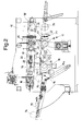
figure 1 is a side elevational view, partially in section, of an exemplified embodiment of the improved gluing unit for an end edge log according to the present invention in a first operative position wherein the log is blocked between an unwinding roller and a forward movement belt; -
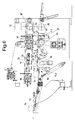
figure 2 is a view similar to that offigure 1 in a second operative position with two logs being fed along the path to reach to receive the glue; -
figure 3 is a view similar to that offigure 2 in successive steps of the second operative position, with two logs being fed along the path to reach to receive the glue; -
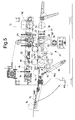
figure 4 is a view similar to that shown infigure 1 in a third operative position, with three logs being fed along the path to reach the glue reception zone; -
figure 5 is a view similar to that offigure 4 in successive steps of the third operative position wherein a log is arranged to pick up the glue; and -
figure 6 is a view similar to that offigure 4 and it shows a final part of the third operative position, wherein the previously mentioned log being fed is overturned to receive the glue. - Referring to the figures, is shown an improved
unit 11 for gluing an end edge of alog -
References - In
particular log 14 shall refer to a log being fed and in the unwinding step, log 14' shall refer to a log in the "timing" step, andlog 14" shall refer to a "timed" log just about to receive a gluing substance. - Right from now, it is pointed out that the term "timing" of a log is used to indicate a process that leads the final free edge of the log to be arranged in a determined angular position in a determined position during the forward movement of the log itself inside the machine.
- The improved gluing unit for an end edge log subject of the present invention, indicated in its entirety with 11 as mentioned, is arranged in a machine for making logs.
- As observable in all the
figures 1-6 this machine generally provides for abearing structure 12 provided with afeeding surface 13 sloped for feeding logs 14 - one after the other, indicated subsequently as mentioned above in the various operative positions also with 14', 14" for better understanding - which come from a preceding rereeling machine arranged upstream and not shown. - As shown in
figure 1 , at the end of the tilted feeding plane 13 a rotatingsorting device 15 of the star type is provided for, having a series ofpockets 15a, which receive thesingle logs 14 and feeds them one after the other towards theactual gluing unit 11 subject of the invention. -
Such gluing unit 11 provides for a firstunwinding roller 16, motorised independent and arranged lower with respect to afeeder belt 17. Thefeeder belt 17 is arranged at the upper part above thegluing unit 11 and it is ring-extended between a pair of end-pulleys 18, 18'. - Arranged at the
unwinding roller 16, preferably immediately downstream, are anair nozzle 19, preferably at the upper part, and asensor 20, preferably at the lower part, such as a photocell, such elements cooperating with thebelt 17, unwind thefinal edge 29 of thelog 14 according to a pre-established amount. - Such configuration is for example shown in
figure 1 . - Arranged at the exit, i.e. subsequently downstream of the
unwinding roller 16 is a first section of thesloped surface 21 which moves thelog 14 to atiming unit 22, also motorised in an independent manner. -
Such timing unit 22, as observable infigures 2 and3 , cooperates with thebelt 17 to arrange thefinal edge 29 of the log 14' in a pre-established position during the forward movement of the log 14' itself. - Provided for downstream of this
timing unit 22 is a second section of a slopedsurface 23 which moves the timed log 14' towards athird roller 24, referred to as suction roller and also motorised in an independent manner. - This
third suction roller 24 is connected to a vacuum source (not shown) and, for such purpose, and it is provided over its entire external lateral surface with suctioning holes adapted to withhold a pre-established portion of thefinal edge 29 of thelog 14" as shown infigures 4 and5 . - Furthermore, this
third suction roller 24 is arranged aligned below anupper roller 25, also motorised in an independent manner, which is moveable vertically towards and away from thesuction roller 24 itself. - Provided for beneath the
feeder belt 17 and immediately after thesuction roller 24 is anyglue dispenser device 27. - In the shown example, this
glue dispenser 27 comprises acontainer 42 holding a gluing substance and arod element 40 which is capable of cyclically being provided with glue on an upperpointed end 43 thereof. - The abovementioned
upper end 43, during or immediately before, theforward moving log 14" is at theglue dispenser 27, due to a mechanism not shown, performs a raising movement, of the vertical type, and comes into contact with the external surface of thelog 14" in motion. - Thus, due to contact, part of the gluing substance held in the
container 42 is released onto an external surface of thelog 14" different from thefinal edge 29 previously withheld by thesuction roller 24 as shown infigure 6 . - Lastly, provided for is an sloping
evacuation surface 34 extended above which is the end part of thefeeder belt 17, which ensures the constraint between thefinal end edge 29 of thelog 14 and the log or roll itself, securely attaining the glue bond. - In particular the
timing unit 22 comprises according to the invention at least one belt orbend element 22, possibly suctioned and/or blown, moveable at a constant speed V22 opposite with respect to the forward movement speed V17 of thefeeder belt 17. - Furthermore, according to the invention the abovementioned speed V22 is always lower than the speed V17 of the
feeder belt 17. - Advantageously the value of the speed V22 can be set by a user according to the diameter of the
logs 14 to be treated, at the beginning of each production cycle by operating on a dedicated motorisation. - In particular such at least one belt or
bend element 22 cooperates with thefeeder belt 17 and positions the free end of thefinal edge 29 of the log 14' in a position arranged according to an angle α with respect to the vertical at the exit of thetiming unit 22 itself. - In particular such angle α depends on the diameter of the log 14', variable factor, and on the length of the second section of
sloped surface 23, constant factor, in such a manner that when thelog 14" itself reaches on thesuction roller 24 by rolling on the second section ofsloped surface 23, the free end of thefinal edge 29" is arranged at the zone of contact of thelog 14" with thesuction roller 24. - The operation of an improved
gluing unit 11 for an end edge log arranged in a machine for the finished making of the log is extremely simple. - The
logs 14, wound almost to their final dimension, are fed on thesloped surface 13 coming from a preceding rereeling machine, arranged in the line. - Each
single log 14 is arranged in apocket 15a of the rotatingsorting device 15 and it is then fed according to a pre-established succession towards thegluing unit 11 of the present invention. - As a matter of fact, as shown in
figure 1 , thelog 14 is arranged on theunwinding roller 16, positioned at the lower part, and it is withheld by theupper feeder belt 17. Theunwinding roller 16 rotates in an anticlockwise direction, while thefeeder belt 17 moves forward in such a manner to exert a given pressure on thelog 14, though rotating it. In such manner, thefinal edge 29 of thelog 14 is moved, by rotating thelog 14, to the blowingelement 19. This blowingelement 19 operates to open the final edge from the rest of thelog 14 and thephotocell 20 detects whether this opening occurs in a sufficient and proper manner. - According to a particular embodiment
such photocell 20 reads the length of theedge 29 when in contact against the firstflat section 21. - At this point, i.e. after the
photocell 20 had detected that theedge 29 has reached a pre-established length, the unwindingroller 16 stops and the continuous forward movement of theupper feeder belt 17 causes thelog 14 to roll on the first section of the slopedsurface 21 moving towards the at least onetiming belt element 22. - In this second operative position, i.e. during the step of passage between the at least one
belt element 22, at the lower part, and thefeeder belt 17, at the upper part, the log - indicated infigure 2 with 14' to distinguish the different step performed by theunit 22 with respect to the previous unwinding performed by the roller 16 - is moved forward rolling in such a manner that at the end of the at least onebelt element 22 the log 14' has the free end of the final edge 29' in a pre-selected position. - In other words, as shown in
figure 3 , at the end of the at least onebelt element 22 the free end of the final edge 29' of the log 14' identifies a given pre-selected angle α with respect to the vertical depending on the diameter of the log 14' and on the length of the secondflat section 23 in such a manner that thelog 14" comes into contact with thesuction roller 24 with such free end of thefinal edge 29". - Upon setting such position at the final edge 29' of the log 14' due to the at least one
belt element 22, the timed log 14' moves on the secondflat section 23 towards thesuction roller 24 due to theupper feeder belt 17. - Due to such rolling, the
timed log 14" joins with the free end of thefinal edge 29" arranged at the zone of contact with the suction roller 24 (also referable to as the six o'clock position of the clock hands infigure 4 ). - The log - indicated with 14" to distinguish the different step performed by the
suction roller 24 with respect to the timing performed beforehand by the at least one belt element 22 - is arranged in the aforedescribed condition between theupper roller 25 and thesuction roller 24. - At this point, the
suction roller 24 is driven to rotate in a clockwise direction and also theupper roller 25 is started to rotate in the clockwise direction. - Consequently, the
final edge 29" is unwound to the pre-established amount, as shown infigure 5 . - Upon termination of this operation, stopping the
upper roller 25 determines the forward movement of thelog 14", while thefinal edge 29" is withheld by thesuction roller 24. In such manner, as observable infigure 6 , theupper belt 17 drags thelog 14" to roll on thepointed end 43 of therod element 40 which moves the gluing substance towards the log itself picking it up from thecontainer 42. - Upon acquiring the glue, the
final edge 29" is released by thesuction roller 24 and theupper belt 17 causes the rolling of thelog 14" on thesloping evacuation surface 34 in such a manner that the glue remains inside the log between the log itself and thefinal edge 29", attaching them mutually. - A
roller 35, arranged on thesloping evacuation surface 34, rotates causing the glued part to be transferred to the upper part of the log preventing the soiling of the surface itself. - It is thus understandable how at least on
belt element 22 cooperating with theupper belt 17 has the important function of "timing" the position of thefinal edge 29, i.e. of the free end thereof, depending on the diameter of the log being treated, variable parameter, and on the length of the slopedsurface 23, fixed parameter, with the aim of always moving the free end of thefinal edge 29" arranged at the zone of contact with thesuction roller 24 as shown infigure 4 . - Advantageously the abovementioned at least one
belt element 22 is connected to a variable motor in such a manner to be able to guarantee the respective abovementioned function in presence of any diameter of the log being treated. - This thus allows the
unit 11 to glue the log of variable diameter, simply due to the variation - to be performed at the beginning of the respective production cycle - of the speed V22 of the at least onebelt element 22. - In this manner a proper positioning of glue on a log to glue the end edge thereto in a quick and accurate manner is performed. Such positioning occurs in rapid succession with several logs being treated simultaneously due to the fact that the timing always occurs with the log moving towards the gluing substance dispenser.
- In this manner, the problems indicated in the introduction regarding gluing units known up to date and used in the log manufacturing industry to make rolls of toilet paper, paper for domestic use and the like were solved.
- As a matter of fact, given that the log is constantly moving along the machine also during the passage over the at least one
timing belt element 22, the production cycle is more efficient eliminating a step wherein, in the known machines, the log did not move forward hence slowing down or requiring interruption of the feeding of the other logs. - Furthermore, advantageously, given that the abovementioned at least one
timing belt element 22 is always in motion, it does not cause any, or causes very little, stresses of the mechanical/vibrational type deriving from a possible intermittent starting of theunit 22 itself. - Lastly, given that the at least one
timing belt element 22 is always in motion, it does not have "on and off" transients, non-instantaneous and scarcely controllable events, hence arranging the final edge of the respective log in an extremely accurate manner thus optimising the subsequent gluing step. - The improved gluing unit for an end edge log of the present invention thus conceived is susceptible to various modifications and variants, all falling within the same inventive concept; in addition, all details may be replaced by technically equivalent elements. In practice, the materials used, as well as the dimensions thereof, may vary depending on the technical requirements.
Claims (9)
- Improved gluing unit (11) for an end edge of a log (14, 14', 14") arranged in a bearing structure (12) of a machine for making logs, wherein said structure (12) has a sloped surface (13) for feeding logs (14, 14', 14") and at the end of said sloped surface (13) a rotating sorting device (15) provided with a series of pockets (15a) for receiving single logs (14, 14', 14") and feeding them towards said gluing unit (11), said gluing unit (11) comprising - at the upper part - a feeder belt (17), moving forward (V17) at a constant speed in the forward movement direction of said logs (14, 14', 14") and cooperates to evacuate the glued log (14, 14', 14"), and - at the lower part - in succession after said rotating sorting device (15) an unwinding roller (16), a first section of sloped surface (21), a timing unit (22), a second section of sloped surface (23), a suction roller (24), connected to a vacuum source arranged above which is an upper roller (25) adjustable in height, a glue dispenser device (27) and evacuation surface (34), further provided for at said unwinding roller (16) being an element (19) for blowing a final edge (29) of said log (14, 14', 14") and a photocell (20) for detecting said final edge (29), characterised in that said timing unit (22) comprises at least one belt element (22) moveable at constant speed (V22) in the opposite direction with respect to said feeder belt (17), said speed (V22) being lower than said speed (V17), said at least one belt element (22) cooperating with said feeder belt (17) and positioning a free end of said final edge (29) of said log (14, 14', 14") in a position arranged according to an angle (α) with respect to the vertical depending on the diameter of said log (14, 14', 14") in such a manner that when said log (14, 14', 14") reaches said suction roller (24) by rolling on said second section of sloped surface (23) said free end of the final edge (29) is arranged at the zone of contact with said suction roller (24).
- Gluing unit according to claim 1, characterised in that said suction roller (24), upon receiving said log in the position with the free end of the final edge (29) thereof arranged at the zone of contact with said suction roller (24), rotates in a clockwise direction, same case applying to said upper roller (25), to unwind the final edge (29) by the pre-selected amount.
- Gluing unit according to claim 2, characterised in that, upon unwinding said pre-selected amount of the final edge (29), said upper roller (25) is blocked to move said log over said glue dispenser device (27) in cooperation with said at least one feeder belt (17) which cooperates to evacuate the glued log towards said evacuation surface (34).
- Gluing unit according to claim 1, characterised in that said at least one feeder belt (17) comprises a first feeder belt upstream of said upper roller (25) and a second feeder belt downstream of said upper roller (25).
- Method actuatable through a unit according to any one of the preceding claims for the application of glue at an end edge of a log wherein the end edge is detached using air and measured in a predetermined length by means of a photocell at an un unwinding roller, and glue is subsequently applied to the log in order to glue said end edge before the same is wound again on the log, so as to be evacuated, characterised in that after said step wherein the end edge is detached and measured by the log, said log is rolled until it reaches a timing belt element where said log is moved forward rolling at a certain angle (α) until the log is arranged in a pre-established position with the final edge in a pre-selected position depending on the diameter of the log being treated, then the log thus positioned is rolled along a section of sloped surface of pre-established length before being positioned on a suction roller with the final end of the end edge arranged at the zone of contact with said suction roller, before the end edge is unwound for a pre-established length and the log is provided with glue.
- Method according to claim 5, characterised in that the rotation of said log (14'), when arranged between said timing belt element (22) and said at least one upper feeder belt (17), is performed in such a manner to position the free end of the final edge (29) offset by a certain angle (α) with respect to its position of arrival in such a manner to arrange said final edge (29) in a pre-established position depending on the diameter of the log (14').
- Method according to claim 6, characterised in that said suction roller (24), upon receiving said log in the position with its free end of the final edge (29) arranged at the zone of contact with said suction roller (24), is rotated in the clockwise direction, same case applying to said upper roller (25), to unwind the final edge (29) by the pre-selected amount.
- Method according to claim 7, characterised in that, upon unwinding said pre-selected amount of the final edge (29), said upper roller (25) is determined to be blocked to move said log over said glue dispenser device (27) in cooperation with said at least one feeder belt (17) which cooperates to evacuate the glued log towards said evacuation surface (34).
- Method according to claim 6, characterised in that the forward movement of said belt element (22) is performed in the direction opposite to the forward movement of said at least one feeder belt (17), said belt element (22) moving forward at a speed that is constant and lower than the forward movement speed of said at least one feeder belt (17).
Applications Claiming Priority (1)
| Application Number | Priority Date | Filing Date | Title |
|---|---|---|---|
| IT000308A ITMI20080308A1 (en) | 2008-02-26 | 2008-02-26 | GLUING GROUP PERFECTED OF AN END OF A LOG |
Publications (2)
| Publication Number | Publication Date |
|---|---|
| EP2096060A2 true EP2096060A2 (en) | 2009-09-02 |
| EP2096060A3 EP2096060A3 (en) | 2010-11-10 |
Family
ID=40291703
Family Applications (1)
| Application Number | Title | Priority Date | Filing Date |
|---|---|---|---|
| EP09153702A Withdrawn EP2096060A3 (en) | 2008-02-26 | 2009-02-26 | Gluing unit for an end edge of a log |
Country Status (3)
| Country | Link |
|---|---|
| US (1) | US20090214757A1 (en) |
| EP (1) | EP2096060A3 (en) |
| IT (1) | ITMI20080308A1 (en) |
Cited By (3)
| Publication number | Priority date | Publication date | Assignee | Title |
|---|---|---|---|---|
| ITMI20100855A1 (en) * | 2010-05-13 | 2011-11-14 | Gambini Int Sa | DEVICE FOR PASTING THE FINAL HALF OF A ROLL OF RIBBED MATERIAL |
| IT201900003885A1 (en) * | 2019-03-18 | 2020-09-18 | Gambini Spa | GLUING DEVICE OF A END OF A LOG. |
| RU2753967C2 (en) * | 2017-03-22 | 2021-08-24 | Филип Моррис Продактс С.А. | Method for removing adhesive label from roll and device for separating adhesive label from the end part of wound sheet in roll |
Citations (1)
| Publication number | Priority date | Publication date | Assignee | Title |
|---|---|---|---|---|
| EP1440925A1 (en) | 2003-01-23 | 2004-07-28 | Giovanni Gambini | Gluing unit of a tail end of a log |
Family Cites Families (4)
| Publication number | Priority date | Publication date | Assignee | Title |
|---|---|---|---|---|
| IT1252896B (en) * | 1991-11-08 | 1995-07-05 | Perini Fabio Spa | IMPROVED EQUIPMENT FOR GLUING THE FINAL EDGE OF ROLLS OF TAPE MATERIAL |
| IT1318995B1 (en) * | 2000-10-11 | 2003-09-19 | Giovanni Gambini | GLUING GROUP OF AN END OF A LOG |
| ITMI20041274A1 (en) * | 2004-06-24 | 2004-09-24 | Giovanni Gambini | PERFECTED GLUE OF A LOG END EDGE AND RELATED METHOD OF GLUING |
| ITFI20070087A1 (en) * | 2007-04-13 | 2008-10-14 | Perini Fabio Spa | METHOD AND DEVICE FOR CLOSING THE FINAL FREE FLUB OF A ROLL OF MATTRIFIED AND ROLLED MATERIAL |
-
2008
- 2008-02-26 IT IT000308A patent/ITMI20080308A1/en unknown
-
2009
- 2009-02-24 US US12/391,639 patent/US20090214757A1/en not_active Abandoned
- 2009-02-26 EP EP09153702A patent/EP2096060A3/en not_active Withdrawn
Patent Citations (1)
| Publication number | Priority date | Publication date | Assignee | Title |
|---|---|---|---|---|
| EP1440925A1 (en) | 2003-01-23 | 2004-07-28 | Giovanni Gambini | Gluing unit of a tail end of a log |
Cited By (7)
| Publication number | Priority date | Publication date | Assignee | Title |
|---|---|---|---|---|
| ITMI20100855A1 (en) * | 2010-05-13 | 2011-11-14 | Gambini Int Sa | DEVICE FOR PASTING THE FINAL HALF OF A ROLL OF RIBBED MATERIAL |
| EP2386510A1 (en) * | 2010-05-13 | 2011-11-16 | Gambini International S.A. | Device for gluing the final edge of a log of a bandshaped material |
| US8302650B2 (en) | 2010-05-13 | 2012-11-06 | Gambini International S.A. | Device for gluing the final edge of a log of a band-shaped material |
| RU2753967C2 (en) * | 2017-03-22 | 2021-08-24 | Филип Моррис Продактс С.А. | Method for removing adhesive label from roll and device for separating adhesive label from the end part of wound sheet in roll |
| IT201900003885A1 (en) * | 2019-03-18 | 2020-09-18 | Gambini Spa | GLUING DEVICE OF A END OF A LOG. |
| EP3712095A1 (en) * | 2019-03-18 | 2020-09-23 | GAMBINI S.p.A. | Gluing device of an end edge of a log |
| US11325803B2 (en) | 2019-03-18 | 2022-05-10 | GAMBINI S.p.A. | Gluing device of an end edge of a log |
Also Published As
| Publication number | Publication date |
|---|---|
| EP2096060A3 (en) | 2010-11-10 |
| US20090214757A1 (en) | 2009-08-27 |
| ITMI20080308A1 (en) | 2009-08-27 |
Similar Documents
| Publication | Publication Date | Title |
|---|---|---|
| EP2403789B1 (en) | Gluing device for logs of wound web-like material | |
| USRE37039E1 (en) | Apparatus for glueing the tail of a web to a log formed of the web material | |
| US7640959B2 (en) | Device for gluing the end flap of a log, and corresponding gluing method | |
| EP1652804B1 (en) | Gluing device of an end edge of a log and relative gluing method | |
| EP1440925B1 (en) | Gluing unit of a tail end of a log | |
| WO2000063099A1 (en) | Device for gluing rolls of web material and associated method | |
| EP2096060A2 (en) | Gluing unit for an end edge of a log | |
| US4723720A (en) | Yarn end finding device | |
| EP2202189B1 (en) | Machine and method for the glueing of the trailing end of a paper roll | |
| US6620241B2 (en) | Gluing unit of a tail end of a log | |
| EP2149529A2 (en) | Apparatus for the gluing of the final tail of rolls or logs of sheet material | |
| US10279371B2 (en) | Gluing device of an end edge of a log and relative gluing method | |
| IT9003583A1 (en) | METHOD FOR THE REPLACEMENT AND REGISTRATION OF PRE-PRINTED TAPE MATERIAL IN AN OPERATING MACHINE. | |
| EP0132862B1 (en) | A device for identification of cheese by applying printed matter | |
| EP2226280B1 (en) | Improved group for gluing the final edge of a log | |
| EP2669229B1 (en) | Package discharging device and yarn winding machine | |
| JPH0524728A (en) | Device to supply roll paper to corrugating machine | |
| JPH0738060U (en) | Bobbin supply mechanism and post-removal inspection mechanism of residual thread removing device | |
| JPH0344993B2 (en) |
Legal Events
| Date | Code | Title | Description |
|---|---|---|---|
| PUAI | Public reference made under article 153(3) epc to a published international application that has entered the european phase |
Free format text: ORIGINAL CODE: 0009012 |
|
| AK | Designated contracting states |
Kind code of ref document: A2 Designated state(s): AT BE BG CH CY CZ DE DK EE ES FI FR GB GR HR HU IE IS IT LI LT LU LV MC MK MT NL NO PL PT RO SE SI SK TR |
|
| AX | Request for extension of the european patent |
Extension state: AL BA RS |
|
| PUAL | Search report despatched |
Free format text: ORIGINAL CODE: 0009013 |
|
| AK | Designated contracting states |
Kind code of ref document: A3 Designated state(s): AT BE BG CH CY CZ DE DK EE ES FI FR GB GR HR HU IE IS IT LI LT LU LV MC MK MT NL NO PL PT RO SE SI SK TR |
|
| AX | Request for extension of the european patent |
Extension state: AL BA RS |
|
| 17P | Request for examination filed |
Effective date: 20110510 |
|
| AKX | Designation fees paid |
Designated state(s): AT BE BG CH CY CZ DE DK EE ES FI FR GB GR HR HU IE IS IT LI LT LU LV MC MK MT NL NO PL PT RO SE SI SK TR |
|
| STAA | Information on the status of an ep patent application or granted ep patent |
Free format text: STATUS: THE APPLICATION IS DEEMED TO BE WITHDRAWN |
|
| 18D | Application deemed to be withdrawn |
Effective date: 20140902 |